

Page 1
CONSOLIDATED
l
__
INDUSTRIAL
SEWING
SEWING
MACHINE
&
CUTTING
CORP.
EQUIPMENT
I
I
CONSOLIDATED
l
__
400
INDUSTRIAL
VETERANS
SEWING
SEWING
BLVD,
I
MACHINE
&
CUTTING
CARLSTADT,
CORP.
EQUIPMENT
NJ
07072
Page 2
INDEX
1.
SPECIFICATIONS ................................. '"........ 1
2.
DESCRIPTION ................................................ 1
3.
SPEED
TO
4
5.
NEEDLES, NIPPLES
.............................................................. 1
OIL
THE MACHINE................................ 2
AND
THREAD
............ 3
TO REMOVE, REPLACE
6.
NEEDLE
7.
TO
THREAD
8.
LEARNING TO OPERATE THE MACHINE 9
9.
TO OPERATE THE
10. TO
11. TENSIONS ....................................................... 10
12. TO ADJUST THE LENGTH OF STITCH ....
13.
14. THE LOOPER .................................................. 12
REGULATE THE PRESSURE
PRESSER FOOT ............................................... 10
TO
REGULATE THE PRESSURE
THE NIPPLE ....................................................
AND
NIPPLE .................................. 4
THE
MACHINE
AND
MACHINE
SET
............ "........ 6
..................... 9
ON
THE
11
ON
11
15. TO SET THE LOOPER .................................. 13
16.
TO ADJUST THE NUMBER OF THE
BRAIDING
TO ADJUST THE TENSION OF THE
17.
BRAIDING
....................................................... 13
.......................................................
14
18. RAY STITCH .................................................. 14
19.
PILE
OR
MOSS
STITCH .................................... 15
Page 3
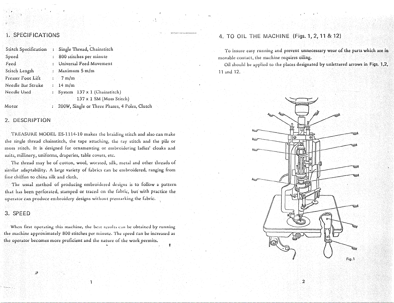
1.
SPECIFICATIONS
4. TO
OIL
THE MACHINE (Figs. 1, 2,
11
& 12)
Stitch
Specification
Speed
Feed
Stitc~
Length
Presser
Needle Bar
Needle
Motor
Foot
u~ed
Lift
Stroke
Single Thread, Chainscitch
800
stitches
Universal
Maximum 5
7m/m
14
m/m
System
200W,
per
Feed
Movement
m/m
137
x 1 (Chaimtitch)
137
x 1
Single
or
minute
SM
(Moss Stitch)
Three Phases, 4 Poles, Clutch
2. DESCRIPTION
TREASURE
rhe single thread chainstitch, the tape attaching, the ray stitch and the pile
moss stitch.
suits, millinery, uniforms, draperies, table covers, etc.
The thread
similar adaptability. A large variety
fint: chiffon
Tht: usual
th«t
has
operator
MODEL ES-1114-10 makes the braiding stitch and also
lr
may
to
china silk and
method
been
P.erforated,
can
produce
is designed for ornamenting
be
of
cotton,
of
stamped
embroidt:ry designs
wool, worsted, silk, metal and
of
cloth.
producing embroidered designs
or
traced on the fabric,
or
fabrics can
without
embroidering ladies' cloaks
be
embroidered, ranging from
premarking the fabric.
other
is
to
follow a
but
with practice the
can
make
threads
pattern
or
aad
of
To
insure easy running and prevent unnecessary wear
movable
11
contact,
the machine requires oiling.
Oil should be applied
and 12.
to
the places designated
by
unlettered
of
the parts which are
arrows
in
in
Figs. 1,2,
3.
SPEED
Whe11
first
the
the
machine
operator
operi!tiug
approximately
becomes more proficient and the nature
thi~
machine, the
800
bc:;r
rc:;uft, can
stitches per minute. The speed can be increased
be
obtained by running
of
the work,permits.
as
2
Page 4
' .
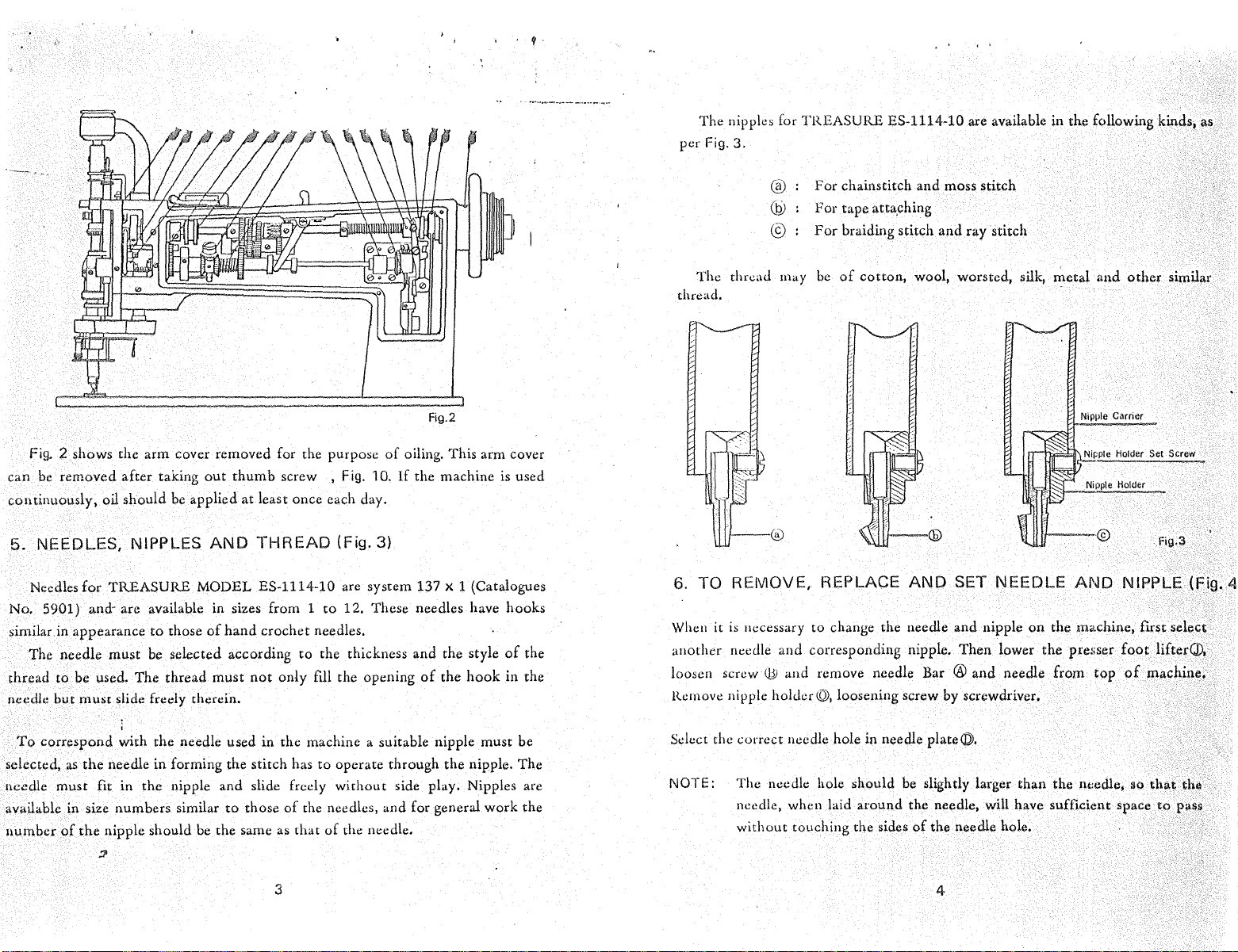
The nipples for TREASURE ES-1114-10 are available in the following kinds1 as
per
Fig.
3.
@
For
chainstitch and moss stitch
~
For tape atta.ching
©
For
braiding stitch
and
ray stitch
Fig.
2 shows the arm cover removed for the purpose
can
be
removed after taking
continuously, oil should
5.
NEEDLES, NIPPLES
Needles
No.
similarin
The
for
TREASURE MODEL ES-1114-10 are system 137 X 1 (Catalogues
5901) and- are available in sizes from 1
appearance
needle
must
to
be
thread to be used. The
needle
but
must
slide freely therein.
out
thumb
be applied
AND
those
of
hand
selected according
thread
must
screw , Fig. 1 0.
at
least once each day.
THREAD
(Fig. 3}
to
12. These needles have hooks
crochet needles.
to
the thickness and the style
not
only
fUl
the opening
Fig.2
of
oiling. This arm cover
If
the machine is used
of
the
hook
of
the
in the
The thread
may
be
of
cotton,
thread.
6. TO REMOVE, REPLACE
When
it
is
necessary to change the needle and nipple
another
loosen screw
Remove
needle
nipple
and
corresponding nipple. Then lower the presser
QJ!
and remove needle Bar ® and needle from top
holder©,
loosening screw by screwdriver.
wool, worsted, silk, metal
AND
SET NEEDLE
on
the machine, first select
and
other
Nipple Carrier
Nipple Holder Set Screw
Nipple
Holder
Fig.S
AND
NIPPLE (Fig; 4
foot
lifterQ).
of
machine,
similar
To
correspond with the needle used in the machine a suitable nipple must be
selected,
needle
available in size numbers similar
number
as
must
of
the
the
needle
in
forming the stitch has
fit
in
the
nipple and slide freely
to
those
nipple should be the same as that
::P
to
operate through the nipple. The
without
of
the needles, and for general work the
of
the needle.
side play. Nipples are
3
Select the correct needle hole in needle plate@,
NOTE: The needle hole should be slightly larger than the nt:edle
needle,
without
when laid around the needle, will have sufficient space
touching the sides
of
the needle hole.
4
ao
that
to
the
pass
1
Page 5
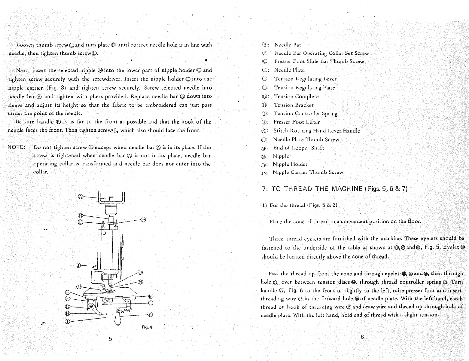
Loosen
needle,
Next, insert
then
thumb
tighten
the
screwQ)an.d
tighten screw securely
nipple
needle bar ®
- sleeve
un<kr the
needle faces the
NOTE: Do
carrier (Fig. 3)
and
adjust its height so
point
Be
sure
handle
screw
and
of
front.
not
tighten screw
is
operating
collar.
turn
thumb
screwQ).
selected nipple
with
the screwdriver. Insert the nipple
and
tighten screw securely. Screw selected needle
plate@
®into
until correct needle hole
the lower
part
of
nipple holder @
tighten with pliers provided. Replace needle
that
the fabric
to
be
embroidered. can
the needle.
®
is
as far
to
the
front
Then
tightened
collar
is
as possible and
tighten screw®, which also should face the front.
Q))
except
when needle bar
uansformed
when needle
(Y
is
not
and needle bar does
that
bar®
is in its place.
in its place, needle bar
is
holder@
bar
® down
the
not
enter
in line
just
hook
into
of
If
into
with
and
the
into
into
pass
the
the
the
@:
Needle liar
(1}>:
Needle liar Operaring Collar
<Q:
Pres5er
Q)J;
Needle Plate
())·
Tension Regulating Lever
(1): Tension Regulating Plate
((;);
Tension Complete
Qj): Tension Bracket
(j):
Tension Controller Spring
(]): Presser
qy;
Stitch Rotating Hand Lever Handle
Q):
Needle Plate Thurnb Screw
<l:Ji;
End
Q{i: Nipple
I.QJ:
Nipple Holder
(!J;
Nipple Carrier
Foot
Slide liar
Foot
Litter
of
Looper Shaft
Thumb
Thumb
Screw
Set
Screw
Screw
5
7. TO THREAD THE MACHINE (Figs.
·1) For the tl1read (Figs.
Place the cone
thread eyelets are furnished with the machine. These eyelets
Three
fastened
to
the underside
should be located directly above the cone
Pass
th<.:
thread up from the cone
hole
0.
over between tension discs
handle
Qv,
Fig. 6 to
threading wire ll): in the forward
thread
011
hook
of
needle plate.
Wilh
5&6)
of
thread in a convenient position
of
the table as shown
of
thread.
and
through eyeletsO, @and(U.
0,
through thread
the
front
or
slightly
hole@
threading
wire®
tlu: left hand, hold
to
the l.eft, raise presser
of
needle plate. With
and draw wire
end
of
thread
6
5,6 & 7)
on
the floor.
at
0.@
controller
and
thread
with
a slight tension.
and
Vi),
Fig. 5. Eyelet 0
then
spring (i).
foot
and
the
left
hand,
up
through
should
through
'turn
insert
catc;h
hole
be
of
Page 6
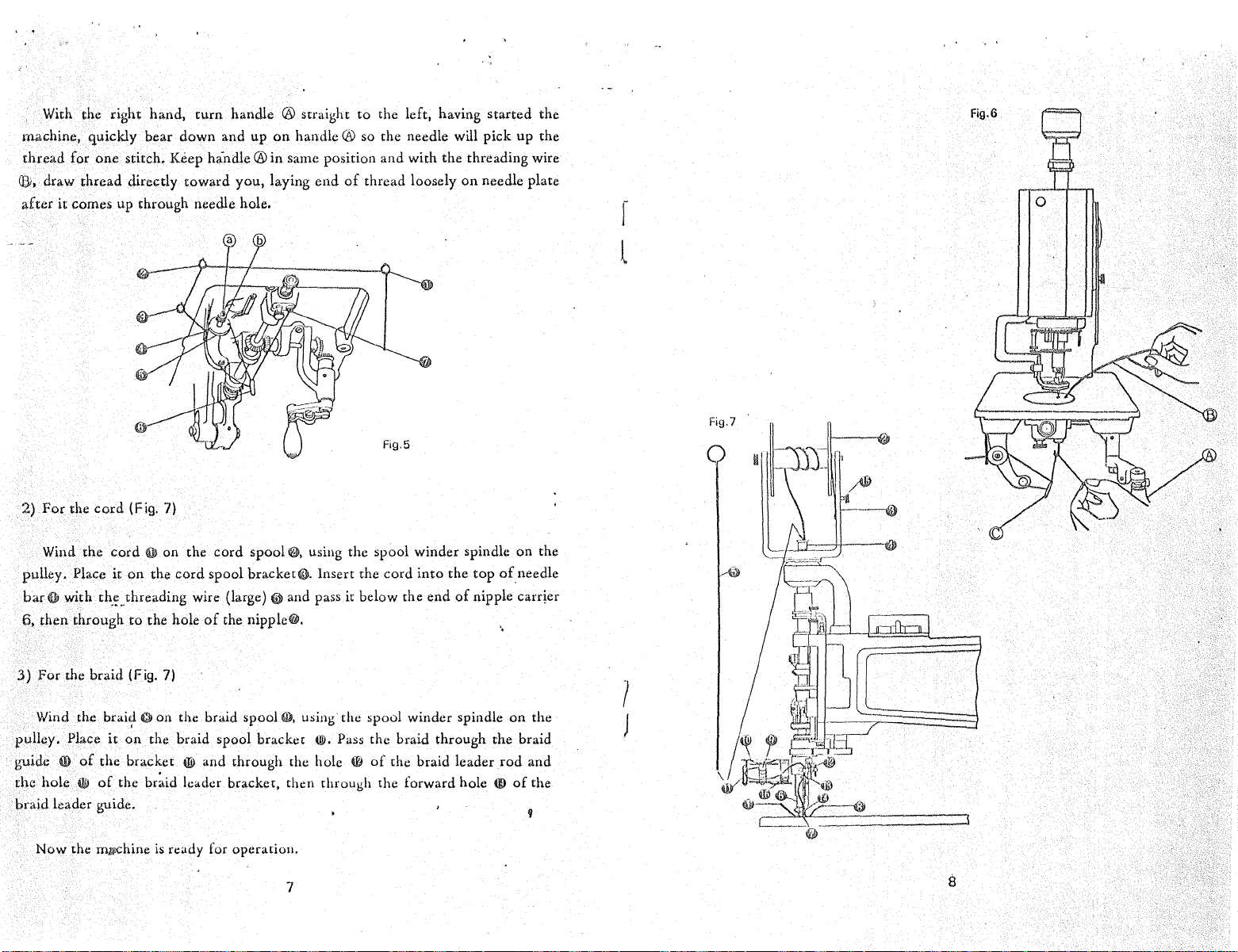
With the right hand,
machine, quickly bear
thread
(6;, draw thread directly
after
2)
for
one
stitch. Keep
it
comes up through needle hole.
For
the
cord
(Fig. 7)
turn
down
hindle@
toward
handle @ straight to the left, having
and up
on
handle®
in
same position and with the threading wire
you, laying
so the needle will pick up the
end
of
thread loosely
started
on
needle plate
the
Fig.6
0
r
l
Wind the
pulley.
barO
6,
then through
3)
For
Wind the
pulley.
guide
4D
the
hole
braid leader guide.
Now
cord
0 on the
Place
it
on
the
cord
spool bracket@. Insert the cord
with
th.~.threading
to
the braid (Fig. 7)
brai~
Gil
Place
it
on
of
the
bracket
4»
of
the
the
mi>Chine
wire (large) 0 and pass it below the
the hole
on the braid spool G), U$ing the spool winder spindle
the braid spool bracket till. Pass the braid through the braid
br~id
is
of
(1il
and through the hole (f)
leader bracket, then through the forward hole (I)
ready for operation.
cord
spool
the nipple€#.
e,
using the spool winder spindle
into
the
end
of
of
the braid leader
7
on
top
of
needle
nipple
carr~er
on
rod
of
the
the
and
the
1
J
8
Page 7
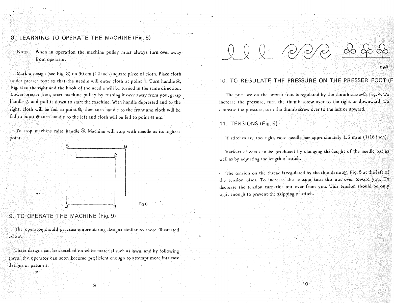
8.
LEARNING
TO OPERATE THE MACHINE (Fig. 8)
Note: When in
from operator.
Mark a design (see Fig. 8)
under
presser foot so
Fig. 6
to
the right and the
Lower
presser foot,
handle
right,
fed
~·and
pull it
doth
will
be
fed
to
point
li) turn handle
To
stop machine raise handle
point.
operation
that
start
down
to
the
machine pulley
on
30
em
the needle will
hook
of
the needle will be turned in the same direction.
(12
inch) square piece
enter
cloth
must
at
always
point
turn
of
cloth. Place
1.
Turn
machine pulley by turning it over away from you, grasp
to
start
the machine. With handle depressed
point@,
to
5
the
then
turn
handle
left
and
cloth
®.
Machine will stop with needle
to
the
will be fed
6
to
front
and
point 0 etc.
cloth
as
2
over away
cloth
handle®,
and
to
the
will be
its highest
10. TO REGULATE THE PRESSURE ON THE
The pressure
increase the pressure, turn the
decrease the pressure, turn the
11. TENSIONS {Fig.
If
stitches are too tight, raise needle
Various effects can be
well
as
by
The
tension
the tension discs.
decrease the tension turn this
tigll t enough
Oil
the presser foot
5)
produced
adjusting the length
on
the thread is regulated by the
To
increase the tension
to
prevent the skipping
is
thumb
thumb
regulated by the
screw over
screw over
bar
approximately 1.5
to
to
the right
the
left
thumb
by changing the height
of
stitch.
thumb
turn
nut
over from you. This tension should be
of
stitch.
nut@, Fig. 5
this
nut
PRESSER
screw©, Fig. 4,
or
downward.
or
upward.
m/m
( 1/16 inch).
of
the needle
at
over
toward
Fig.9
FOOT (Fi!
To
To
bar
as
the
left
of
you.
To
ox:ly
4
9. TO OPERATE THE MACHINE (Fig.
The
operator; should practice embroidering d.:signs similar
3
9)
Fig.8
to
those illustrated
below.
These designs can
them,
the
operator
designs
or
patterns.
;P
sketched on white material such as lawn,
can
soon become proficient enough
9
to
and
attempt
by following
more intricate
b,~
10
Page 8
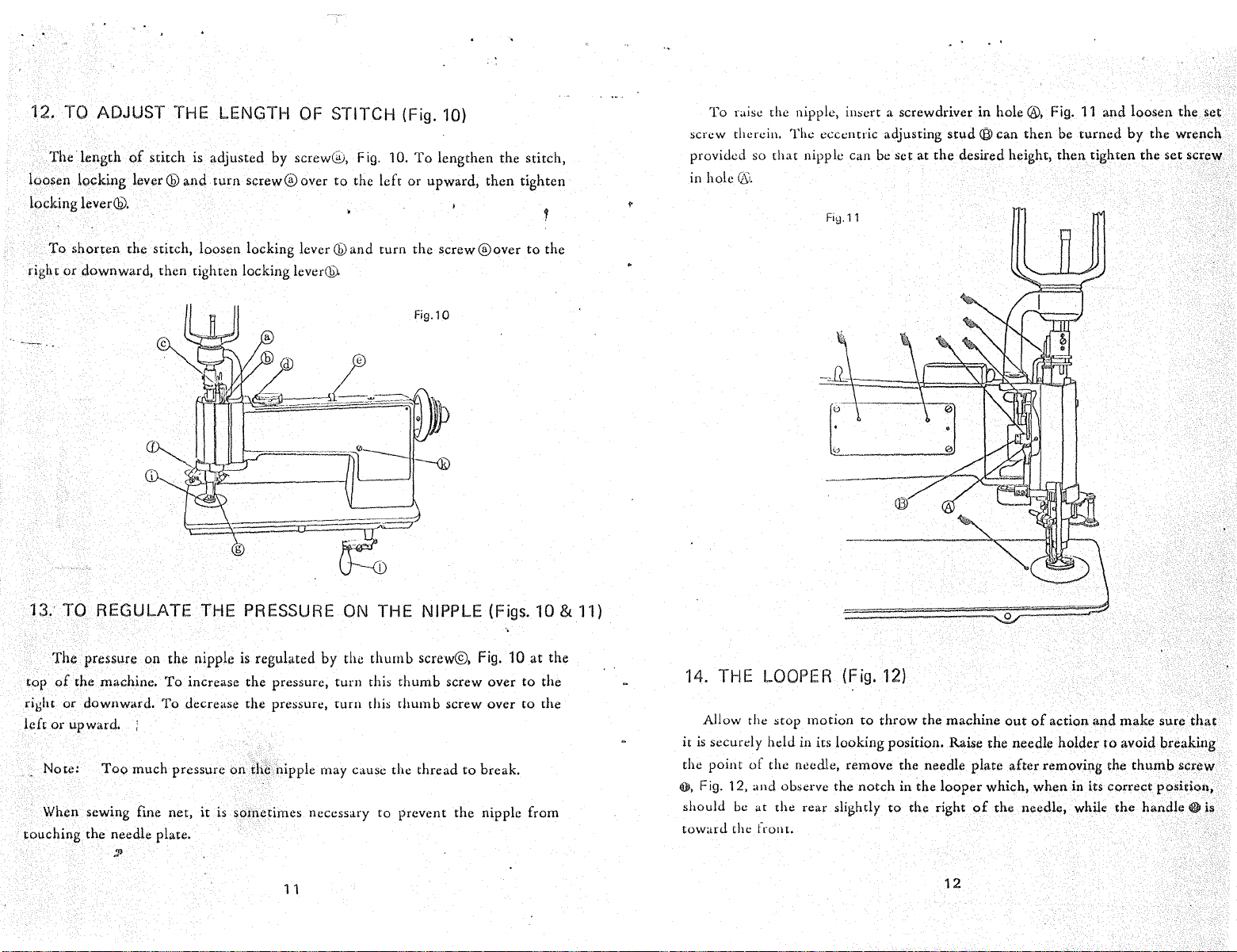
12. TO ADJUST THE LENGTH
The
length
loosen locking
locking
right
lever@.
To
shonen
or
downward, then tighten locking
of
stitch
is adjusted by screw@, Fig.
lever®
the stitch, loosen locking
and
turn
screw®
OF
STITCH (Fig.
over
to
lever®
lever®
and turn the screw
the
10.
left
10)
To
lengthen the stitch,
or
upward,
then
®over
tighten
to
the
To
raisl! the nipple,
screw therein. The eccentric adjusting
provided so
in
hole®.
that
in~ert
a screwd1·iver in
nipple can be set at
Fiy.11
the
hole®.
stud®
can
desired height,
then
Fig.
11
and loosen the set
be
turned
then
by
tighten the set screw
the wrench
13. TO REGULATE THE PRESSURE
The
pressure
top
of
the machine.
right
or
downward.
left
or
upward. ;
Note:
When sewing fine net,
touching
the needle plate.
on
Too
much pressure
:J'
the nipple is regulated by the
To
increase the pressure,
To
decrease the pressure,
on
the nipple may cause the thread
it
is sometimes necessary
11
ON
THE NIPPLE (Figs. 10 & 11)
turn
turn
thumb
this
this
screw@,
thumb
thumb
to
prevent the nipple from
Fig.
screw over
screw over
to
break.
10
to
to
at
the
the
the
14. THE LOOPER (Fig.
Allow the stop motion
it
is
securely held in
point
the
0,
Fig. 12, and observe the
should
toward
of
be
at the rear slightly
the front.
its
looking position. Raise the needle holder
the needle, remove the needle plate after removing the
12)
to
throw
notch
the machine
in the
to
the right
out
of
action
and
to
looper
which, when in its correct position,
of
the needle, while
12
make sure
avoid breaking
thumb
the
handle~
that
screw
is
Page 9

15.
TO
SET
Turn
the machine
Fig. 4
to
the
front.
turn
the gear slightly,
instructed
shaft~,
above.
tighten the set screw@. .
THE
LOOPER (Figs. 4 & 12)
back
on
its hinges
Loosen
After
set
until
the
having set
screw(!), Fig. 12
notch
the
and
turn handle
of
in the
worm
looper
gear flush with th\!
t),
Fig. 12
the operating
is
in its
worm
correct
end
and
gearO,
position
of
the
screw®,
and
as
looper
Note: Do
17.
TO
It
is
brackdr;
To
adjll~~
it docs
and
from you.
over
bracket\f;by the left hand
!lOt
turn
To
increase the tension
toward
lf
the geMs do
not
change the lever while
cause the machine
ADJUST
the best for
Fig.
a:; above, bring the handleQ)to front,
turn
the
braid spool bracket(Oto the above position.
To
decrease the tension
you.
THE
the
10
is
set in the left while
round, then press the gear changing lever@, Fig. 10
not
engage
the
clutch is engaging.
to
damage.
TENSION OF
normal braiding embroidery works
of
the
braiding,
of
the braiding,
after
the
and
turn
the pulley by the right
THE
BRAIDING
the
handle
CD
is
hold
turn
the
braid
turn
above adjustment,
at
the
the
the
hand.
If
do
so, it
may
(Fig. 10)
that
the braid spool
front.
handle
by
the knee as
to
the right
spool bracketCDover
braid
spool bracketeD.
. ~ f
('•
h?ld
the braid spool
16.
TO
The
number
located
engage and
ing
embroidery.
ln
ca~c
of
In
ca~c
of
In
case
of
In
case
of
The
bigger
Therefore,
ADJUST
on
the
the
the
number
the
n~mber
the
number
the
number
the
set
the number 1 for normal braiding stitch.
:I'
THE
NUMBER
of
the
braiding can be adjusted
top
of
the machine frame.
machine will be
1, one braiding (roll) per one stitch
2,
3,
4,
1/4
number
operated
1/2
braiding (roll) per one stitch
1/3
braiding (roll) per one stitch
braiding (roll) per one stitch
is
set, the coarser the internal
OF
as chainstitch, moss
13
THE
At
BRAIDING
by
the lever@, Fig. 10, which
the
number
of
the braiding will be.
0,
the
stitch
(Fig. 10)
gears do
or tape attach-
is
not
Note:
·The
""·
Fig.
18.
The
tensions
(1)
For
loosen the screwll},
Do
do so,
additional
7 and the braid leader guidajp,
RAY
STITCH (Figs. 4 &
r:•y
stitch
of
the cord and the braid slightly tight as
loosening thread (fig. 4)
not
prc~s
the gear changing lever
it may cause the machine
adjustment
will be made
7)
Citll
be
done
by
adjusting the tensions
Fig.
4 and lift the needle
Fig.
14
to
damage.
by
the braid
10.
®while
you
like.
bar®
the
spool
of
so
that
clutch
adjusting
the
thread
th,e
thread
is
engaging.
thumb
loos.:,
loosens.
If
nut
the
'
Page 10

' '
(2)
For
tightening
cord
(Fig. 7)
tighten the screw {lil, Fig. 7 so
slow.
(3) For tightening braid (Fig. 7)
· tighten the
nut
~.
Fig. 7 so
slow.
Then,
set
the
lever
@)
, Fig.
that
that
10
to
the number 1.
the rotation
the
rotation
of
the cord
of
the braid spool
spool~
becomes
0becomes
19. PILE
OR
MOSS
The raised pile or moss stitch
the
will drop
handle®,
the
hook
the
screw
knurled
stitches in loose loops on the materials.
Fig. 4 w the front, loosen the
of
the needle will
$.
Reach
end
0,
Fig. 12
left and while holding it
then release the knurled
The
looper-
will
then be set in the opposite direction
for the chain stitch,
-~hile
handle(!), Fig.
10
(spur).
By
operating
circles
of
The higher the
thickness
the machine and
dropp~d
stitch loops laid one on the other, raised pile. work
needle
of
the
material used will have
machine for pile stitching.
STITCH (Figs. 4,
is
produced by adjusting the machine so
point
directly
under
the bed
of
the operating worm ·gear 0 draw
turn
end
of
or
with
is
at
the
is
set the longer the loop will be. The size
of
the machine with the left hand, grasp the
handle
~around
the gear.
the
notch
front. Change the pn:sser
turn
handle(l)rapidly, so
10
& 12)
screw<.IY
to
the back
and
turn
of
to the right directly
of
the looper
to
be considered when adjusting the
To
accomplish this,
the needle
the machine,
th;
worm gear
to
that
which is required
at
the front
footCDto
the presser
as
to
make very small
of
bar®
of
the
then
to
is
thread
that
turn
so
that
tighten
t&
the
the back,
~.he
needle
foot
produced.
and
it
<"
I
15
Page 11

Machine Frame & Covers Components
Ref. No.
1
2
3
4
5
6
7
8
9
lO
11
12
PMtS
No.
AJ\11114·10
ol81
8470
5227
8466-A
4015
8434
8150
8483
S-8445
8172
8146
Description
Machine
Arm
Arm
Arm
Spool Can:iex
Spool Canier
Arm
Arm
Arm
Cord Spool Bracket Supporting Ann with
Cord
Cord Spool Bracket Supporting
Top
Head
Head
Side
Side
Side
Spool
Frame
Screw
Cover
Cover
Cover
Cover
Cover
Brackllt
Thumb
Driving
Driving
Position
Thumb
Scxew
Gear Cover
Gear
Cove.r
Pin
Screw
SupportiJli
Sll~
Ann
Arm
·Scxew
Clamp
Position
Needle
Scxew
l)in
Bea{ing
7
-11
rr:-12
9
'
TK-111-10
Page 12

I'
•
7
9·'------~--------------~
ll
16
I
18
;_
20
.
19
I
~13
·
.
~13
®1)~
\
17
17
221i
~
~
12
21
23
3
Page 13

Arm Head Part5 Component:)
\No.1)
14
27
Ref. No. Parts No.
64 72 Arm Head
1
8020
2
8021 Arm Head Screw
3
4
8022
5 815 0 Arm Head Position
9
6 8145 Arm Head Position Pin
S-8462
7
8
11152
9
4031
10· 84
11
12
13
14
15
16
17
18 8463 Spool Carrlllr ldlllr Gear Supporting Block ·
19
20
21
22
23 8335 Nipple Set Scn;w ·
24
25
26
27
28 84
29
30
31
32
33
34
35 8311 Feed Sliae Block
36
3 7 8 314
39
40
41
42
43
74 Spool Carrier Driving Gear Cover Bracket
4 015 Spool Carrier Driving Gear Cover Bracket
8452-A
8465 Nipple Carrier Sleeve
8464 Spool Carrier
8461
8475-C
2553-A
113-A
8320-A
8339
8498-A-3
8510-AA
8027-3
8449
831 Needle Bar Guide Block & Collar
77
84 76 Needle Bar Guide Block
8308
5176-A
8030
129-B
S~8456
8312
ll;\ 1 "\
124
8335 Feed Lever Bracket
8037
8036
8038
Arm
H11ad
Arm Head Screw (lower)
Spool Carrier Driving Gear Guide with Ref.
SpoQl Carrier Driving Gear Guide Screw
Spool Carrier Driving Gear Guide
Nipple Carrier Sleeve with Screws
Spool
Carrier
Spool Carrier Driving Idler Gear
Spool Carrier Driving Idler Gear
Spool Carrier Idler Gear Supporting
Nipple Holder · · · ·
Nipple Holder Set Screw
Nipple (for Braiding)
Needle Bar
Needle
(137xl
Arm Head Sleeve
Needle Bar Guide Block Set Scfew (Large) ·
Arm Head Sleeve Cap ·
Arm Head Sleeve Cap Screw
Arm Head Sleeve Gear
Arm Head Sleeve Gear Set Screw
Feed Rotating Shaft & Gear
Feed Lever
Feed
Lever Hinge Pin
Ft>ed
Lever Bracket
Feed Lever Bracket Set Screw
Feed Recovering
Feed
Recovering Spring (Left)
Feed Recovering
Description·
Screw (upper)
(upper)
Pin
Buiihit13
Driving
G6ar
Driving
Idler
#3)
Set
Spt1113
Spril13
(lon~)
(shQtt)
Gear
Stud
Stud
Set
Sc~ew
Screw
(RI&bt)
Screw
Set
Screw
Set
Block
..
with
(Small)
No.8
Set
Screw
'·
Screw
Set Sctew
·· .·
Ref; Nos. 28
....
2~
'\
Page 14

Arm
Huad Parts Componant$ (No. 2)
Parts
1:1067
8161
8065
8139
8138
8064
8140
8069-A
IH!!8
8070-A
S-8453
8072
8481-A
8454-A
8073-D
8315
8316
8136
8310-A
8428
4173
8317
8051
8055
8182
8054
8160
8052
~IJSl
8041
8048
No.
-A
l're5ser
Presser
Presser
Presser
Presser
Press~r
Presser
Presser
Presser
Presser
Presser
Presser
Presser
P(esser
...
Presser
Presser
Presser
Pn:sser
Feed
Feed
Feed
Feed
Feed
Fee<!
Nipple
Nipple
Nipple
Nipple
Nipple
Nipple
~ip\)1$
Feed
Fee<!
Ref.
No.
2
3
4 8066
5 8322
6
7 8063
8
9
10
11
12
13
14
.,
'
15
16
17
7
32
18
19
20
21
\
8
22
23
24
25
26
27
[~
10
I
15
28
29
30
31
ll
33
34
Description
Foot
SW1o
Foot
Slide
Foot
Slide
Foot
Slide
Foot
Slide
Foot
Slide
Foot
Slide
Foot
Slide
Foot
Slide
Foot
Slide
Foot
Lever
Foot
Lever
Fuot
Levex
Foot
Lever
Foot
Clamp
Foot
Clamp
Foot
Foot
Shoe
Lever
Bracket
Lever
Bracket
Leve.r
Bracket
Slide
Bar
Slide
Bar
Block
Slido
Bar
Block
Curies
Carrier
Guide
Caxdw
Gui<!e
Carrier Thumb
Carrier Thumb
Casrt.r
Spdlli
Canw
Extt>m\Qn
Reg~
tin& Sctew
Regulating
Bar
Thllrnb
Bar
Thumb,Scxew
Bar
Spxin&
Bar
Sprini
Bar
Bar
Adjustina
Bar
Guide
Bu
Guide
Bu
Spdng Stop
Bat
Spdlli Stop
Swivel
Swivel
Swivel
Thumb
(Rubber)
Guide
Guide
G\lide
Sot
Screw
Screw
SCA:eW
Screw
Lock
SlllOW
Nu.t
PlUilil:lf
SCA:ew
Set
Screw
Scxew
Stop
SCA:lJW
Hingt~
Screw
Sclew
.
I
Cap
Cap
Scn>w.
SCA:QW
N1,1t.
Levlj)tN~t
· ·
1
Page 15

7
~
5
/9
I
~
Description
Crank
Cmier
Bell
Crank
Foot
Slide Bell Crl4lk
Foot
Slide Bell Crank Hinge
Foot
Slide Bell Crank
Foot
Lifter
Foot
Lifter Hinge Screw
Thumb
Screw
Stud
Stud
Hin;:e
with
Set
S!f!eW
Sttu1
Stud
H.inge
Ref. No$.
Set
Stud
Stul!
17-18
Sc&ew
Set
Se~ew
10
11
12
13
14
15
16
17
18
19
20
21
22
No.
2
3
4
5
6
7
8
9
Parts No.
8042
8044
8045
8046
8043
5225-C
8057
8455
5225-C
1>059
3455
5225-C
8060-A
3061
1)304
1>27
827-1
411>5
84()4
1>26
124
8467
Feed Bell Cranl';
Feed Bell Crank RoUer
Feed Bell Crank Roller Scxew •
Feed Bell Crank Spring
Filed Bell Crank Hinge
Feed Bell Crank Hinge
Nipple CMrier Bell
Nipple
Nipple CMrier Bell Crank Hinge
Presser
Prllm:r
Presser
Presser
Presser
Needle Bar Operating Slide
Braid Leader Assembly
Braid Leader Guide
Braid Leader Guide Set Screw
Braid L.:ader
Spool Carlier Assembly
Spool Carrier Set Qcrew
Braid Spool (Metal)
Ref.
15
6
16
~
1\:l
"
-
20
9
21
~
22
Page 16

Gear Change Lever, Spool Carrier
Components
DisenQ<!Qing
Lever~
~24
~-23
Ref. No.
2
3
4
5
6
7
8
10
11
12
13
14
15
16
1
16
17
Hl
19
20
21
22
23
2-lc
Parts
8439
8440
8441
8435
113-ll
8437-1
8437-2
8437-3
8438
.;,,
84;,:,
8491
8489
5207
8514
8416
129-B
S-84t
129-A
8415
8414
114-B
81-lc6
'JQ
No.
7
Description
Gear
Change
Gear
Change
Gear
Change
Gear
Change
Gear
Change
Gear
.change
Gear
Change
Gear
Change
Gear
Change
Spool Carrier
Spool Carrier
B
Spool Carrier
Spool Cauier
')1
Canier
Carrier
Spo,,
rier
lntennL
lmermed,..:.
lntermedi;ue
Intermediate
Intermediate
Intermediate
lntermediat~:
lmermediate
Lever
Cover
Levex
Cover
Graduated
Lever
Base
Lever
Base
Lever
Lever
Spring
L.evo::r
Ball
Lever
Set Saew
Disengasing
Disengaging
Dist:ngagiog
Disengaging
Disengaging
Disengaging
Disengagillg
Gear
(No.1)
·H
Set
•
Assembly
Gc~l
" t
Gear
Gear
B,~,,;
Gear
Br<~~·
Gear
Brack<;.
Set
Screw
Plat~!
Set
Screw
Lever
Leves
Sprin&
Lever
Spring
Lever
Bracke$
L~ver
Stt+d
L.ev~rr
Stud.
L.everCover
Screw
(No.
Screw
Scfew
Nut
2~4)
22
19
•'
Page 17

feed
Rotating Gear &
Stop
Bracket Pa.ru Componentli
/24
~
lO
:at)
11
16-....
i
'-1
17
~
22
Ref.
No.
2
3
4
5
6
7
8
9
10
11
12
13
14 8081
15
16
17
18
19
20
21
22
23
24
25
26
Parts No.
3424
113-A
8146
8423-A
8142
8420
8422-A
8142
8112-B
821
8442
ts079
8486
121
8443
8083
124
8084
8077
8078
8075
8076
8473
8172
8159
Do5Crlp,tion
Feed Rotating Shaft
Feed Rotating Shaft
Feed Rotating Shaft Brackllt:Posjtion
Filed Rotating
Feed Rotating Gear Set Screw
Stitch Rotating Shaft
Stitch Rotating Gear (Upper)
Stitch Rotating Gear Set Screw
Stitch Rotating Gear (Lower)
Stop Bracket Assembly (Ref. Nos.
Stop Bracket
Stop Brackl':tlnteilocking Rod
Stop Bracket Interlocking Rod Spring
Stop Bracket lnterlockinl) Stop Block
Stop Bracket Interlocking Stop Block Screw
Starting Trip Lever Slide
Starting Trip Lever Slide
Starting Trip Lever Sli\le Cap Screw
Starting Trip Lever Sli\le Spring
Stop
Cam
Roller
Stop
Cam Roller Screw
Stop
Cam Rocking Lever
Stop
Cam
Rocking Lever Hinge
Stop Bracket Set
Stop Bracket Set Screw (Short)
Stop Bracket Position Pin
Geu
SCiew
B&a~et
Bra~et
Set
(Rear)
Cap,,
Stu\1
(Long)
SCiew
:Pin
11-23)
SCiew
l
I
S:~l
13
. '
Page 18

Foed Rotating
Shaft
Mechanism Compononu
Pans
Ref. No,
1
2
3
4
5
I'
•
6
7
8
9
10
11
12 8142
13
14
15
16 8146
17
18
19
20 8504
21
22
23
24
25
26
27
28
29
30
No.
8110-A
8142
8458
8459
4078
8460
129-A
8097-A
129-B
8457
8097
Spool Cauier
Spool Carrier
Spool Carrier
Spool Canicr
Spool
Spool Carrier
Spool'Can:ier
Spool Carrier
Spool Carrier
Spool Carrier
Spool Carrier
Spool Carrier
8427
8496
8429
Spool
· Spool Carder
Spool
Spool
8495
S-8425
8492-T
Spool
Spool Carder
Spool Carrier
Spool Carrier
8433
129-B
8432
8431
Feed Rotating Shaft
Feed Rotatins Shaft
Feed Rotating Shaft
Feed Rotating Shaft
8479 Feed Rotating Shaft
8430 Feed Rotating Shaft
5262
Feed Rotating Shaft
10017-A Feed Rotating Shaft
8142
8421
Feed Rotating Shaft
Feed Rotating Shaft
0&$cription
Ca.rde•
Caxrier
Ca.rriex
Caxrier
Carrier
Gear
Driving
Gear
Drivinz
Gear
Driving
Gear
Drivin~
Gear
Driving
Gear
Driving
Gear
Driving
Gear
Driving
Gear
Driving
Gear
Driving
Gear
Driving
Gear
Driving
Geax
Driving
Gear
Driving
Gear
Driving
Gear
Dr
Gear
Driving
Gear
Driving
Gear
Driving
Gear
Driving
Gear
Gear
Gear
Block
Block
Block
Block
CoUax
Collar
Bevel
Gc:ar
Bevel
Gear.
Gea,t
Shaft
Gear
Slu!it
Gear
Shaft
Gear
Gear
Set
Bevel
Gear
Bevel
Gear
Bevel
Ge-ar
Bevel
Gear
Bevel
Gear
Bevel
Geill'
Bevel
<;lear
Bevel
Gear
ivins
Bevel
Gear
Bevel
Gear
Sle~ve
Gear Assembly
Sleeve
Gear
Sleeve
Gear
(Small)
Set
SCLeW
{Lax$e)
Set
SCLew
Pin
Pin
Se'
Set
SCLew
Set Screw
Bushing
:Bushing
Screw
Set
S.;:rew
Sleev~
Set
Scxew
Set
S(:lew
Btacket
B&a~et
Blacl\.et
Sprl,ng
'Thrt!st
·
SCLe.w
Set Screw
Taper
Pi~
Washer
Beaxins
30
15
,·
Page 19

'
I
14
~~13
8
'
16
n
17
~
I
I
18
'
Looper
Ref.
No.
1
2
3
4
5
6
7
8
9
HJ
ll
12
13
14
15
16
17
18
19
20
21
22
23
24
25
26
27
28
29
30
31
32
33
34
35
36
"'
~~
Operating
Pam
No.
1!106
8107
805
8104
8105
8102
8103
806
8100-A
8101
124
8099
8152
129-B
8158
8150
822
S-8444
8174
8175
8176
8177
8178
8179
5207
8089-A
8092
8093
8090
8091
8088
8143
8149
8094
8097·~A
1;142
Muchaoism
Needle Plate
Needle Plate Clamping Thumb
Looper
Looper Operating Collar
Looper Operating Collar Set
Looper
Looper Operating
Looper Bracket
Looper
Looper Position Plate
Looper Position Plate
Looper Bracket
Looper
Looper
Looper Bracket Set
Looper Bracket Position
Looper Operating Connection
Looper Operating Connection , ,
Looper Operating Connection Joint Pitman
Looper Operating Connection Joint Pitman Nut (Upper).
Looper
Looper Operating Connection
Looper Operating Connection Joint
Looper Operating Connection Joint
Looper Operating
Looper Operating
Looper Operating
Looper Operating
Looper Operating
Looper Operating
Looper Operating
Looper Operating
Looper Operating
Looper Operating
Looper
ComponenU
Screw
Operatin&
Oper;>ting
Collar
Collar
Operating Connection Joint
Opera
Gear
Gear
Gear
Assembly
Set
Screw
Connection
Bell
Bell
Bell
Bell
Bell
Bell
Bell
Bell
Shaft
tin&
Sbaft
Assembly
Scu~w
(Spiral)
Spring
(Ref.
No$.
Screw
Sci:ew
Pin
Assembly
Joint , ,
Joint
Crank
Crank
Hinge
Crank
Hinge
Crank
Hinge
Crank
Hinge
Crank
Bracket
Crank Bracket Set
Crank Bracket
,
Bevel
GtJJ
(Ret'.
NO$.
9-
14)
(Ref.
PHman
Hinge
Stud
Hinge
Stud
Hin&e
StMd
Block
Block Screw
Screw
Screw Nut
Screw
Position
{l,dl)
4 -· 7)
NoJ,lS
Nl.lt
(Lowef)
Sprin&Wa~er
Nut
·
Pin
- 28)
·
11
Page 20

19
2~,"
'
·"
·~·~
..
;4~5
<
33
~35
3~<
36
~
I
;j]
34
39
Rut.
No.
"'
9
1()
1 t
12
13
l4
15
16
17 5107
lll
19 8117
20
21 lH42
22
23
24 8142
25 8113
26 8143
27 8149
28 8122
29 !H23
30
31
32 8119
33
34 8120
35 8121
36
S-8115-A
37
38
39 8116
40
41
f'afl>
No.
~ill
ol21
lil:~JJ
4HIJ-A
l:ll
liW
til
5267-A
.HSH)·-A
8164
1.\143
8110-A
·
8114-A
8096-A
8124
!lOS
8045
5176-A
8118
5070
8141
Ot>${;fipdOfl
Tcm.i.:w
T .:n>l.:.n .i'i4te
Tlln.lou
'l'tnlion Still!
Ten:>ion
Ten~on
Stitch
Stitd1 Rotatin&
Stiteh
Stitch
Stitch
Utat::k.£1
Du.:
Stud Nnt
lhac~t
Rat<Ltin&
Rotat~
R<Hating
RoJating
Stitch Rotating
Stitch Rotating
Stitch Rotating
Stitch
Rotating
Starting
Tdp
Lever
Startil~
Trip
Lever
Starlin&
Trip
Lever
Stitch Rotatlni
StaniJ~
Trip
Starting Trip
Starting Trip
Statting Trip
Lever
bver
Lever
Lever
Stitch Rotating
Stitch Rotating
Stitch Rotating
Stitch Rotating
Stitch Rotatmg
Stiteh Rotatillg
Al>~<iillbly
Set
Stxew
Gear
Rxl!.l:kllt
Geilt
~tacket
Hand
Lever
Hand.Levet
Hand
Gear
llrackot
Gear
Bracket
Gear
llKacket
Rod
(Intermediate)
Hinse
Han«
Hinge
Block
Block
Hand
Hand
Hand
Hand
Hand
Hand
(RiiJ'.
Not.
Shaft
Stu.ft
Lever
Shaft
&It
Po~tiQn
Screw
Lever
liand!e
Screw
· ·
Screw
Stlui
Lever
with fin&,
Lever
Set
Sccew
Lever
Hancih!
Lever
Handle
Lever
Hilncile
Leverlb,ndle
2
Ceaz
·
Ctar
~~
&;le\\1
Sl:HlW
·
Ptn
As.wmbl¥
Screvr
· · · ·
Sleev.,
SletW;J
Wilmer
Sl~;~ve
S1:1ew
(RI)f;
Page 21

----
Cord Spool &
Belt
Cover Compommts "
3
"@
I
{
I
\
5"
k
10
~
~
11
Description
Spool
Spool
Spindle
Spool Spindle Washer
Spool Spindle
Spool Bracket
Spool
friction
Spool
Friction
Spool
Friction
Spool
Bracket Sleeve with Screws
Spool Bracket Sleeve
Spool Bracket Sleeve
Cover
(Left)
Set
Screw
EXTRA
ACCESSORIES
Thumb
Nut
Sprin~
Spring Screw
Spring Adjusting Scxew
Set
Screw
Thrust
Bearing
12-
19)
.,
10
ll
"'12
'"13
"14
"15
"16
*17
*18
"'19
"20
l
2
3
4
5
6
7
8
9
Parts No.
8336
8331
70l2·A
8332
8487
8329
8140
4356
8448
98
8446
830
8503-1
8503-2
5276
8185
11554
5233
11557
8184
Cord
Cord
Cord
Cord
Cord
Cord.
Cord
Cord
Cord
Cord
Cord
Belt Cover Assembly (Ref. Nos,
Ddt
Bult Cover (Right)
Belt Cover
Belt Cover Washer
!ielt Cover Bracket
Belt Cover Bracket Set Screw
Belt Cover Bracket Wood Sctew
Belt Cover Wood Screw
"'
Ref. No.
8
-
fl
13
12
21
Page 22

Standard Accassories
3
~----~
6
-
~
Ref. No.
Pans
No.
AC~Ol
l
2
AC-02
AC-03
3
4
AC-04A
5
AC-05
6
AC-08
7
8166
8 8157
9
8165
8493
10
11
8126
8171 Plieu
12
13
8168
14
8170
8169
15
8499
16
17 8156
18
8497
19
5249
20
8073-B
8027-3
21
22
8501-4
23
8321-4
24 8505 Presser
25
8467 . Braid Spool (Metai)
26
8502
AC~~06
27
Description
Screw Driver (Large)
Screw Driver (Medium)
Sw1w Driver (Small)
Oller
ou
Acce~sory
Screw
Bed Clamping Thumb Screw
Machine Hinge Connection
Tool (for Adjustinz Hinge Stud #84SS)
Spool Screw Stud
Thread Knife
Twee1.er&
Machine Rest Pin (Wood)
Cleaning
Threader
Spool Winder Spindle
Spool Winder Spindle Washer
Presser
Needle
Nipple (for Chainstitching)
Nipple (for Tape·Attaching)
Spool
Wrench
Box
Eye
Wife
Wife
Foot
(l37xl
Foot
(Woo<!)
(3
mm)
J.~
Shoe (Rubber)
#3)
(Spur)
{fl
~
"'
. ,
~27
23
Page 23

f\iumerical Parts· List
Part$ No.
AC-01
AC.Q2
AC-03
AC-04A
AC.Q5
-
AC-n8
81 19
!=c.
98
c
•••
..
113-A
ll3·B
114-B
121
124
129·A
l29·B
131 3
132
805
806
808
810
811
821 13
822
!
__
824 3
826
827,827-1
.
830
~
831 . 5
At.Hll4-10
2SS3·A
4015
4031
4105
Parts
Pat:e
23
23
23
No.
4140-A
4173
4185 9
23 4356
23
23
21
.
5,13 5190·A
11 5207 11,19
11
13,19
5,9,13,17 5233 21
11,15
5,11,15,17 5262
..
3
17
17
19
19
19
17
9
9
21
1
5
1,5
5
-
11
5070 19
5162·B
5176·A
5176-A
5225-C
5227
5249
5266 3
5267·A 19
5276
8005-A
8006 3
8008 3
8009·A 3
8010 3
8012
8013 3
8014 3
8015 3
8017-B
8018 3
8020 5
8021
8Q22
8027
8030
Page
.
23
15
21
5,23
19
7
21
11-
5
19
19
9
1
3
3
3
5
5
5
Parts
No.
8036
8037.
8038
8042
8043
8044
8045
8046
8047 7
8048
8051
8052
8053
8054
8057 9
8059 9
806Q.A
8061 9
8063 7
8064 7
8065
8066
8067
8069·A 7
8070 7
8072 7
8073·B
·8075
8076
8077
8078
8079
8081
8083
Page
9,19
7,23
13
13
13
13
13
13
13
Parts
5
5
5.,
9
9
9
9
7
7
7
7
7
r-------~--~-+--------r-~~~-------+--~~1
8084
8088
8089-A
8090
• 8091
8092 17 8128 19 8175
8093
8094 · 17 8130-A 19 8117 11 I
8095-B
8096-A 17,19 8!32·A 19 8!79 = --··_._1_1._,.,.j
8097
8097·A 15,17 8136 7
~--------,_-------+----------r-~~--+---------+-----~~1
8098-B
8099
8100-A
8101
No.
9
7
7
7
8102
8103
8104
~---s_1o_s
r----s_I~o6
r---------1--------+---------~------~------·~~------~
t--~----;......-----
~---81_2_o
__ ~ _____
__
_,
8107 17 8150 1,5,17
8110·A 15,19 8152
8112-B
8113 19 8157
8114-A
S-8115-A 19
8116
8117 19
8118
8119
__
,_
8121 19 8166
8122 19 8168
Page
__
~_1_7
19
19
19
19
____
l9
Parts
13
17
17
17
No.
8123
8124
8125 19 · 8171 23 .
8126 23 8172 1,13
Page
19
19
l~h
No.
8169 23
8170 23
f~~
>
I.
17---~---8-l-27--~----l-9--+----8-l7-4---r~-ml~1-4.
17
17
15
17
17
17
17
17
17
17
l_7
13
__
__
__
+-
----------~~--~~
8129-A
8131 19 8178
8133·A
8138 7 8184
8139 7
8140 . 7,21 8304 . 9 I
8141
8142 13,15,17,19 8310.A 7
8143 17,19 8311
8145 s 8312 s
r-
___
8_1_46
__
~r-1~,1_1~,1_3,~l_sr-
+-
___
s_l_4_9
__
-r
8156
8158
8159
816o 1 8322·A 1 < r
8161 7 8329
8164 19
___
s_l_65~-+~--2_3~r----83
19
19
8!76
81tH
8!82
818:5
19
__
1_7~,1~9~+----8·~314~~----~s~
17
23
23
17
13
8308 s
___
s
__
31~3--~~~~s~
831.5
8316 · 1
831'7
8320.A S
8321-4 23
._:_-+---..--~
8332
__
3s
__
~----··S_
23
23
8336
.,
8339 s
..
.:. . . •.•
.. · ·.
21
a!'
21
17
11
11.
21
21
·.
..
1
1
s
7
1'
,-;
..
;
..
<
..
•••
...
···
.·
I
1
.
I·
I
· '
......
25
Page 24

·-
..
'
Parts No.
8403
8404
8405
1)406
~-
.
l
'~~-
!
.
r
;
8407
8408
~
8410
·:.8411'
~8412
.
8414
8415
8416
S·8417
.
.I!•UO
8421
8421·A
8423·A
8424
S·842.S
8421
8428
8429
8430
8431
8432
8433
8434
8435
13>417·1
8437·2
8437·3
S438
8439
---
Page
11
11
11
11
13
15
13
13
13
15
15
3
3
3
3
3
3
3
3
3
..
3
Parts
I
S-8444
$-8445
S·ll453 7
S·8456 5
'•
S·8462
8463 5 8504
1
15
15
15
15 8470
15
1
11
u.
u
11
11
11
8465
8466·A
8467
8472
8473
8474
i41S.C
8476
No.
8440
8441
8442
8443
8446
8448
8449
8452·.-1.
8454·A
8455 9
8457
8458
8459
8460
8461
8464
8477
8479
8480.A
Page Parts No.
11
-
11
13
13
17
11
11 8490
'5
15
15
15
15
9,23 10017-A
5
13
5
5
15
848l·A
8483
8484
8486
8487
1 8488
8489
8491
5
7 8495
5
5
5
5
1
1
5 •
5
3
8492-T
8493
8496
8497 13
8498·A s
8499
8501~4
8502
8503-1
8503-2
8505
8510.,AA
8514
11152
11554
11557
.
..
•
.
.
.
98·A
l3l.C
8188
8055
4078
7012·A
AC·06
F
,/
Page··
7
1
9
13
11
.11
11
11
uf
15
13
15
15
23
23
23
21
21
15
23
5
11
IS
5
21
21
3
l
7
7
15
21
23
J.
 Loading...