

Page 1

104-10T
PARTS BOOK
AND INSTRUCTION MANUAL
Page 2

INDEX
1. SPECIFICATIONS ..............................................................................2
2. DESCRIPTION ................................................................................... 2
3. SPEED ................................................................................................ 2
4. TO OIL THE MACHINE ......................................................................3
5. NEEDLES, NIPPLE AND THREAD ...................................................4
6. TO REMOVE, REPLACE AND SET NEEDLE AND NIPPLE ............5
7. TO THREAD THE MACHINE .............................................................7
8. LEARNING TO OPERATE THE MACHINE .......................................10
9. TO OPERATE THE MACHINE ...........................................................10
10. TO REGULATE THE PRESSURE ON THE PRESSER FOOT ..........11
11. TENSIONS .......................................................................................... 11
12. TO ADJUST THE LENGTH OF STITCH ............................................12
13. TO REGULATE THE PRESSURE ON THE NIPPLE .........................12
14. THE LOOPER .....................................................................................13
15. TO SET THE LOOPER .......................................................................14
16. TO ADJSUT THE NUMBER OF THE BRAIDING ..............................14
17. TO ADJUST THE TENSION OF THE BRAIDING ..............................15
18. RAY STTICH .......................................................................................15
19. PILE OR MOSS STITCH ....................................................................16
20. PARTS LIST .......................................................................................17~
1
Page 3

1. SPECIFICATIONS
Stitch specification : Single thread, chainstitch
Speed : 1500 stitches per minute
Feed : Universal feed movement
Stitch Length : Maximum 5 m/m
Presser foot lift : 7 m/m
Needle bar stroke : 14 m/m
Needle used : System 137 x 1(chainstitch)
137 *1 SM (Moss stitch)
Motor : 200W(1/4HP), Single or three phase, 4 poles, clutch
2. DESCRIPTION
Embroidery machine makes the braiding stitch and also can make the single
thread chainstitch, the tape attaching, the ray stitch and pile or moss stitch. It is
designed for ornamenting or embroidering ladies’ cloaks and suits, millinery,
uniforms, draperies, table cover, etc.
The read may be of cotton, wool, worsted, silk, metal and other threads of similar
adaptability. A large variety of fabrics can be embroidered, ranging from fine chiffon
to china silk and cloth.
The usual method of producing embroidered designs is to follow a pattern that
has been perforated, stamped or traced on the fabric, but with practice the operator
can produce embroidery designs without premarking the fabric.
3. SPEED
When first operating this machine, the best results can be obtained by running
the machine approximately 800 stitches per minute. The speed can be increased
as the operator becomes more proficient and nature of the work permits.
2
Page 4
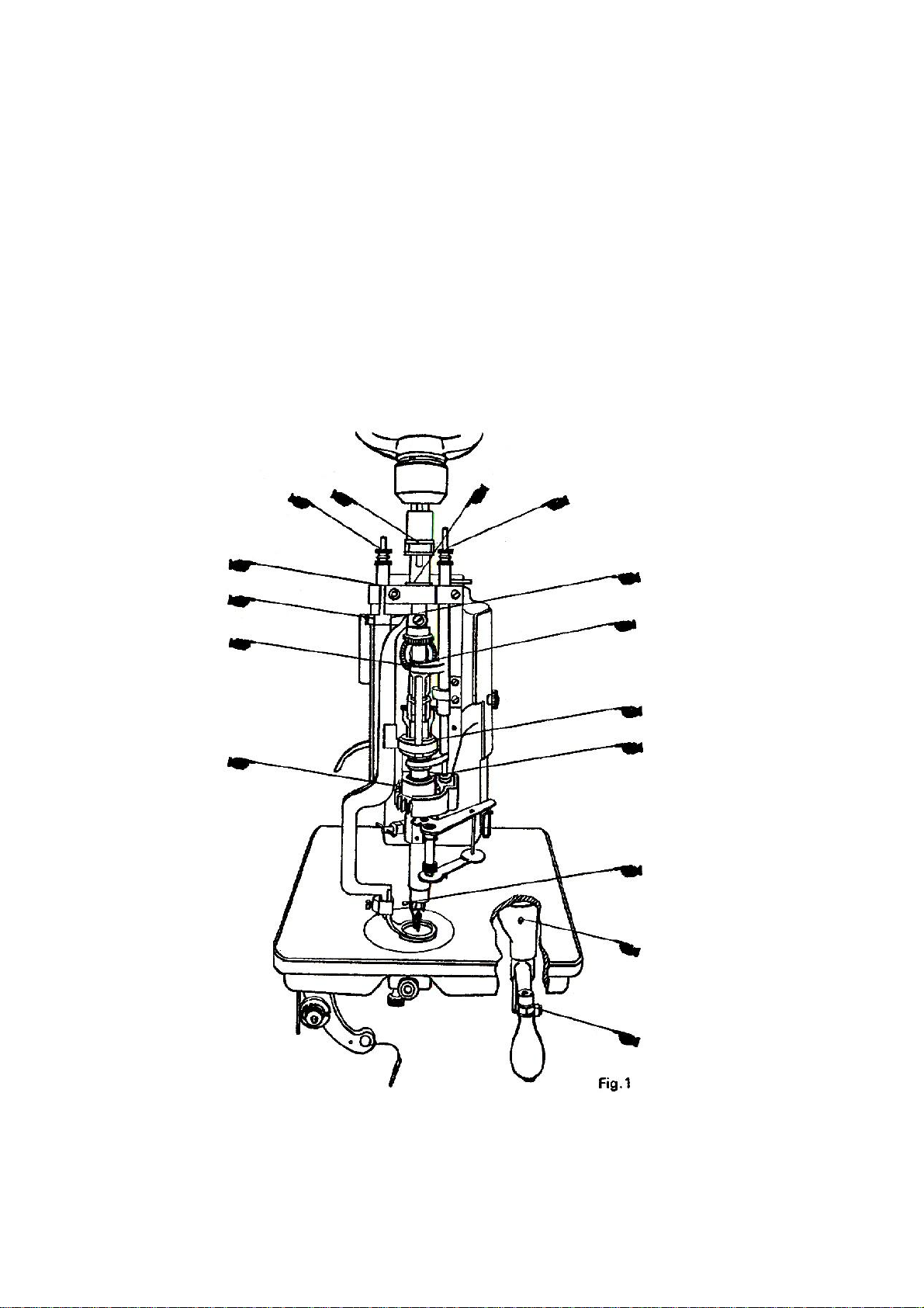
4. TO OIL THE MACHINE (Fig. 1, 2, 11 & 12)
To insure easy running and prevent unnecessary wear of the parts which are in
movable contact, the machine requires oiling.
Oil should be applied to the places designated by unlettered arrows in Fig.
1,2,11and 12.
3
Page 5
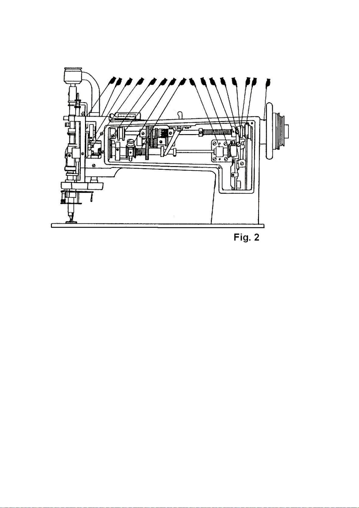
Fig. 2 shows the arm cover removed for the purpose of oiling. This arm cover can
be removed after taking out thumb screw, Fig. 10. If the machine is used
continuously, oil should be applied at least once each day.
5. NIPPLES, NIPPLES AND THREAD (Fig. 3)
Needles for embroidery machine are system 137 x 1 and are available in sizes
from 1 to 12. These needles have hooks similar in appearance to those of hand
crochet needles.
The needle must be selected according to the thickness and the style of the
thread to be used. The thread must not only fill the opening of the hook in the
needle but must slide freely therein.
To correspond with the needle used in the machine a suitable nipple must be
selected, as the needle in forming the stitch has to operate through the nipple. The
4
Page 6

needle must fit in the nipple and slide freely without side play. Nipples are available
in size numbers similar to those of the needles, and for general work the number of
the nipple should be the same as that of the needle.
The nipples for embroidery machine are available in the following kinds, as per
Fig. 3.
(a) : For chainstitch and moss stitch
(b) : For tape attaching
(c) : For braiding stitch and ray stitch
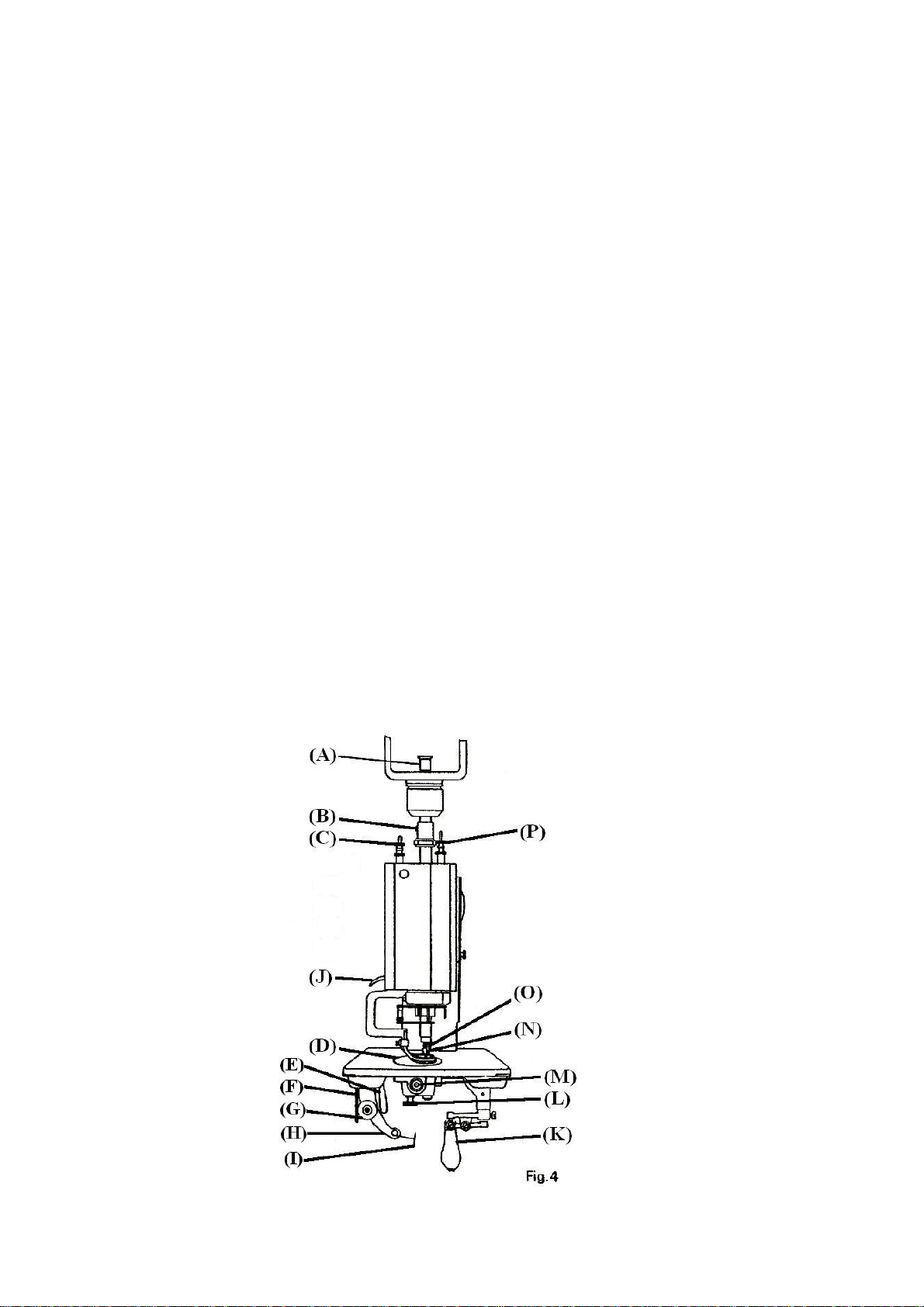
6. TO REMOVE, REPLACE AND SET NEEDLE AND NIPPLE (Fig. 4)
When it is necessary to change the needle and nipple on the machine, first select
another needle and corresponding nipple. Then lower the presser foot lifter (J),
loosen screw (B) and remove needle bar (A) and needle from top of machine.
Remove nipple holder (O), loosening screw by screwdriver.
Select the correct needle hole in needle plate (D).
NOTE: The needle hole should be slightly larger than the needle, so that the
5
Page 7
needle, when laid around the needle, will have sufficient space to pass
without touching the sides of the needle hole.
Loosen thumb screw (L) and turn plate (D) until correct needle hole is in line with
needle, then tighten thumb screw (L).
Next, insert the selected nipple (N) into the lower part of nipple holder (O) and
tighten screw securely with the screwdriver, Insert the nipple holder (O) into the
nipple carrier (Fig. 3) and tighten screw securely. Screw selected needle into
needle bar (A) and tighten with pliers provided. Replace needle bar (A) down into
sleeve and adjust its height so that the fabric to be embroidered can just pass under
the point of the needle.
Be sure handle (K) is as far to the front as possible and that the hook of the
needle faces the front. Then tighten screw (B), which also should face the front.
NOTE: Do not tighten screw (B) except when needle bar (A) is in its place. If the
screw is tightened when needle bar (A) is not in its place, needle bar operating
collar is transformed and needle bar does not enter into the collar.
6
Page 8

A. Needle bar
B. Needle bar operating collar set screw
C. Presser foot slide bar thumb screw
D. Needle plate
E. Tension regulating lever
F. Tension regulating plate
G. Tension complete
H. Tension bracket
I. Tension controller spring
J. Presser foot lifter
K. Stitch rotating hand lever handle
L. Needle plate thumb screw
M. End of looper shaft
N. Nipple
O. Nipple holder
P. Nipple carrier thumb screw
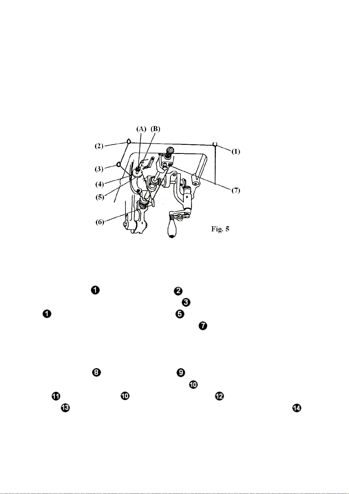
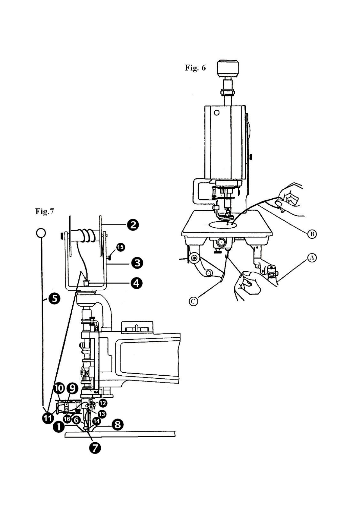
7. TO THREAD THE MACHINE (Figs. 5, 6 & 7)
1) For the thread (Figs. 5 & 6)
Place the cone of thread in a convenient position on the floor.
Three thread eyelets are furnished with the machine. These eyelets should be
fastened to the underside of the table as shown at (1), (2) and (3), Fig. 5. Eyelet (1)
should be located directly above the cone of thread.
Pass the thread up from the cone and through eyelets (1), (2) and (3), then
through hole (1), over between tension discs (5), through thread controller spring
(6). Turn handle (A), Fig. 6 to the front or slightly to the left, raise presser foot and
insert threading wire (B) in the forward hole (7) of needle plate. With the left hand,
catch thread on hook of threading wire (B) and draw wire and thread up through
hole needle plate. With the left hand, hold end of thread with a slight tension.
7
Page 9
With the right hand, turn handle (A) straight to the left, having started the
machine, quickly bear down and up on handle (A) so the needle will pick up the
thread for one stitch. Keep handle (A) in same position and with the threading wire
(B), draw thread directly toward you, laying end of thread loosely on needle plate
after t comes up thread needle hole.
2) For the cord (Fig. 7)
Wind the cord
pulley. Place it on the cord spool bracket
bar
with the threading wire (large) and pass it below the end of nipple
on the cord spool , using the spool winder spindle on the
. Inter the cord into the top of needle
carrier 6, then through to the hole of the nipple
3) For the braid (Fig. 7)
Wind the braid
on the braid spool , using the spool winder spindle on the
pulley. Place it on the braid spool bracket
guide
the hole
of the bracket and through the hole of the braid leader rod and
of the braid leader bracket, then through the forward hole of the
.
. Pass the braid through the braid
braid leader guide.
Now the machine is ready for operation.
8
Page 10
9
Page 11
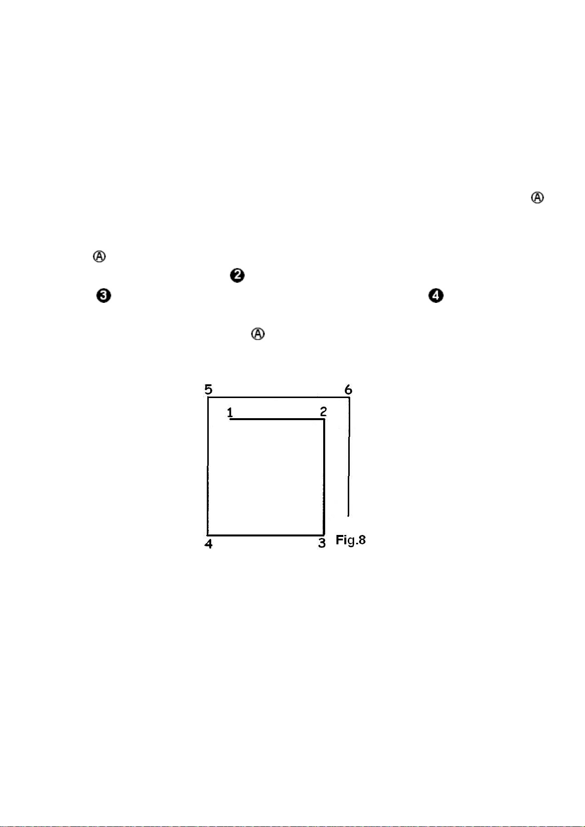
8. LEARNING TO OPERATE THE MACHINE (Fig.8)
Note: When in operation the machine pulley must always turn over away from
operator.
Mark a design (see Fig.8) on 30cm (12 inch) square piece of cloth. Place cloth
under presser foot so that the nee
ig. 6 to the right and the hook of the needle will be turned in the same direction.
F
dle will enter cloth as at point 1. Turn handle
,
Lower presser foot, start machine pulley by turning it over away from you, grasp
handle
right, cloth will be fed to point
to point
and pull it down to start the machine. With handle pressed and to the
, then turn handle to the front and cloth will be fed
turn handle to the left and cloth will be fed to point etc.
To stop machine raise handle
. Machine will stop with needle as its highest
point.
9. TO OPERATE THE MACHINE (Fig. 9)
The operator shou
below.
These designs can be sketched on white material such as lawn, and by following
them, the operator can soon become proficient enough to attempt more intricate
e
d signs or patterns.
ld practice embroidering designs similar to those illustrated
10
Page 12

10. TO REGULATE THE PRESSURE ON THE PRESSER FOOT (Fig.4)
The pressure on the pre
crease the pressure, turn the thumb screw over to the right or downward. To
in
de
crease the pressure, turn the thumb screw over to the left or upward.
sser foot is regulated by the thumb screw
, Fig.4. To
11. TENSIONS (Fig.5)
If stitches are too tight, raise needle bar approximately 1.5 /m (1/16 inch).
Various effects can be produced by changing the height of the needle bar as well
as by adjusting the length of stitch.
The tension on the thread is regulated by the thumb nut
e tension discs. To increase the tension turn this nut over toward you. To
th
ecrease the tension turn this nut over from you . this tension should be only tight
d
m
, Fig. 5 at the left of
nough to prevent the skipping of stitch.
e
11
Page 13
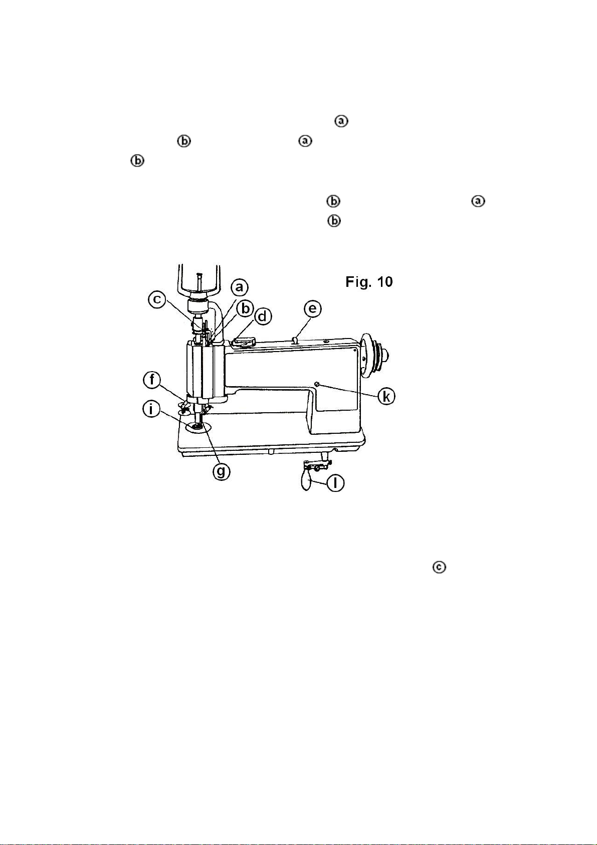
12. TO ADJUST THE LENGTH OF STITCH (Fig. 10)
The length of stitch is adjusted by screw
osen locking lever
locking lever
.
and turn screw loover to the left or upward, then tighten
To
shorten the stitch, loosen locking lever
right or downward, then tighten locking lever
, Fig. 10. To lengthen the stitch,
and turn the screw over to the
.
13. TO R
EGULATE THE PRESSURE ON THE NIPPLE (Fig.10 & 11)
The pressure on the nipple is regulated by the thumb screw
f the machine. To increase the pressure, turn this thumb screw over to the right or
o
, Fig. 10 at
the top
downward. To decrease the pressure, turn this thumb screw over to the left or
upward.
Note: Too much pressure on the nipple may cause the thread to break.
When sewing fine net, it is sometimes necessary to prevent the nipple from
touch
ing the needle plate.
12
Page 14

To raise the nipple, insert a screwdriver in hole , Fig. 11 and loosen the set
screw therein. The eccentric adjusting stud
can then be turned by the wrench
provided so that nipple can be set at desired height, then tighten the set screw in
hole
.
14. THE LOOPER (Fig. 12)
Allow the stop m
securely held in its looking position. Raise the needle holder to avoid breaking the
point of the needle, remove the needle plate a
ig. 12, and observe the notch in the looper which, when in its correct position,
F
sh ,
ould be at the rear slightly to the right of the needle while the handle
toward the front.
otion to throw the machine out of action and make sure that it is
fter removing the thumb screw
,
is
13
Page 15

15. TO SET THE LOOPER (Fig. 4 & 12)
Turn the machine back on its hinges and turn handle
Fig. 4 to the front. Loosen set screw
, Fig. 12 of the operating worm gear .
, Fig. 12 and screw ,
And turn the gear slightly, until the notch in the looper is in its correct position as
instructed above. After having set the worm gear flush with the end of the looper
shaft
, tighten the set screw .
16. TO ADJ
UST THE NUMBER OF THE BRAIDING (Fig. 10)
r
The number of the braiding can be adjusted by the leve
lo e gears do not engage
cated on the top of the machine frame. At the number 0, th
an titch or tape attaching
d the machine will be operated as chainstitch, moss s
em
broidery.
, Fig. 10, which is
In case of the number 1, one braiding (roll) per one stitch
In case of the number 2, 1/2 braiding (roll) per one sti
tch
In case of the number 3, 1/3 braiding (roll) per one stitch
In case iding (roll) per one stitch
of the number 4, 1/4 bra
The bigger the number is set, the coarser the internal of the braiding will be.
Therefore, set the number 1 for normal braiding stitch.
14
Page 16

Note: Do not change the lever while the clutch is engaging. If do so, it may cause
the machine to damage.
17. TO ADJSUT THE TENSION OF THE BRAIDING (Fig. 10)
It is the best for the nor al braiding embroidery
b
racket
To adjust as above, bring the handle
it does not tu
rn the braid spool bracket
tu
To increase the tension of the braiding, turn the braid spool brac
ou. To decrease the tension to the braiding, turn the braid spool bracket
y
toward you.
If the gears do not engage after the above adjustment, hold the braid spool
bracket
Note: Do not press the gear changing lever
, Fig. 10 is set in the left while the handle is at the front.
rn round, then press the gear changing lever
by the left hand and turn the pulley by the right hand.
m works that the braid spool
to front, hold the handle by the knee as
, Fig. 10 to right and
to the above position.
ket
while the clutch is engaging. If
over from
over
do so , it may cause the machine to damage.
The additional adjustment will be made by the braid spool adjusting thumb nut
, Fig. 7 and the braid leader guide , Fig. 10.
18. RAY STITCH (Fig. 4 & 7)
The ray stitch can be done by adjusting the tensions of the thread loose, the
tensions of the cord and the braid slightly tight as you like.
(1) d
For loosening threa (Fig. 4)
Loose
n the screw
, Fig. 4 and lift the needle bar so that the thread
15
Page 17

loosens.
For tightening cord ig. 7)
(2) (F
Tighte
low.
s
n the screw
, Fig. 7 so that the rotation of the cord spool becomes
(3
) For tightening braid (Fig. 7)
Tighten the screw
, Fig. 7 so that the rotation of the braid spool becomes
slow.
Then, set the lever
, Fig. 10 to the number 1.
19. PILE OR MOSS STITCH (Fig. 4, 10 & 12)
The raised pile or moss stitch is produced by adjusting the machine so that it will
drop the stitches in loose loops on the materials. To accomplish this, turn handle (K),
Fig. 4 to the front, loosen
the screw (B) and turn the needle bar (A) so that the hook
f the needle will point directly to the back of the machine, then tighten the screw
o
(B
). Reach under the bed of the machine with the left hand, grasp the knurled end
, Fig. 12 of the operating worm gear draw the worm gear to the left and while
holding it turn handle
knurled
end of the gear.
around to the right directly to the back, then release the
The looper will then be set in the opposite d ection to that which is required for
ir
the chain stitch, or with the notch of the looper at the front of the needle while
handle
, Fig. 10 is at the front. Change the presser foot to the presser foot
(spur).
By operating the machine and turn handle
rapidly, so
circles of dropped stitch loops laid one on the other, raised pil
he higher the needle is set the longer the loop will be. The size of the thread and
T
as to make very small
e work is produced.
thickness of the material used will have to be considered when adjusting the
machine for pile stitching.
16
Page 18

1. MACHINE FRAME & COVERS COMPONENTS
17
Page 19

REF. NO.PARTS NO
.
A
P1-1 AM1114- 10MACHINE FRAME
P1-2 8181 ARM TO P SCRE W
P1-3 8470 ARM HEAD COVER
P1-4 5227 A RM HE AD COVER THUMB SCREW
P1-5 8466P1-6 4015 SPO OL CARRIER DEIV ING GEAR COVER SET SCREW
P1-7 8434 ARM S IDE COVER
P1-8 8150 ARM SI DE COVER POSI TION PIN
P1-9 8483 ARM SIDE COVER THUMB SCREW
P1-10 S-8445 CORD SPO OL BRACKE T SUP PORTING ARM WITH NEEDLE BE ARING
P1-11 8172 CORD SPOOL BRACKET SUPPORTING ARM CLAMP SCREW
P1-12 8146 CORD SPOOL BRACKET SUPPORTING ARM POSITION PIN
SPOOL CARRIER DRIV ING GEAR COVER
DESCRIPTION
18
Page 20

3. ARM SHAFT MECHANISM COMPONENTS
19
Page 21

REF. NO. PARTS NO
.
A
A
A
A
DESCRIPTION
P3-1 8403 ARM SHAFT BUHSING
P3-2 98-
ARM SHAFT BUSHING SET SCREW
P3-3 8404 DRIVING PULLEY SLEEVE BUSHING
P3-4 131 DRIVI NG PULLEY SLEEVE BUSHING SET SCREW
P3-5 8406 ARM SHAFT GEAR SLIDING KEY
P3-6 8407 ARM SHAFT GEAR SLIDING KEY SPRING
P3-7 824 ARM SHAFT A S SE M B LY WITH REF. NOS. 8-10
P3-8 8008 STOP CAM
P3-9 8163-B STOP CA M DRIVING STUD
P3-10 8005-
NEEDLE DRIVING CAM POSITION SCREW
P3-11 8006 NEEDLE DRIVING CAM ROLLER
P3-12 5266 ARM SHAFT COLLAR
P3-13 132-C ARM SHAFT COLLAR SET SCREW
P3-14 8405 ARM SHAFT GROOVED COLLAR
P3-15 8480-
ARM SHAFT GROOVED COLLAR SET SCREW
P3-16 8408 ARM SHAFT GEAR (NO. 1)
P3-17 8412 ARM SHAFT GEAR WASHER
P3-18 8409 ARM SHAFT GEAR (NO. 2)
P3-19 8410 ARM SHAFT GEAR (NO. 3)
P3-20 8411 ARM SHAFT GEAR (NO. 4)
P3-21 8009-
STOP CAM SPRING
P3-22 8010 STOP CAM SPRING COLLAR
P3-23 132 STOP CAM SPRING COLLAR SET SCREW
P3-24 8012 ARM SHAFT DRIVING FLANGE
P3-25 8013 ARM SHAFT DRIVING FLANGE POSITION SCREW
P3-26 8014 ARM SHAF T DRIVING FLA NGE SET SCREW
P3-27 8017- B DRI VI NG PULLEY
P3-28 8015 DRIVING PULLEY SLEEVE
P3-29 8018 DRIVING PULLEY SLEEVE SCREW
20
Page 22

5. ARM HEAD PARTS COMPONENTS (NO.1)
21
Page 23

A
A
A
A
A
A
A
A
K
A
A
A
A
A
A
A
A
A
REF. NO . PARTS NO.
P5-1 8472
P5-2 8020
P5-3 8021
P5-4 8022
P5-5 8150
P5-6 8145
P5-7 S-8462 SP OOL CARRIER DRI VI NG GEA R GUIDE WITH REF . NO.8
P5-8 11152 SPO OL CARRIER DRIVING GEAR GUIDE SCREW
P5-9 4031 SPOOL CARRI ER DRIVI NG G EAR GUIDE SET SCREW
P5-10 8474 SPOOL CARRIER DRIVI NG GEA R COVER BRACKET
P5-11 4015 SPOOL CARRIER DRIVI NG GEA R COVER BRACKET SET SCREW
P5-12 8452P5-13 8465 NIPPLE CARRIER SLEEVE BUSHING
P5-14 8464 SPOOL CARRIER DRI VI NG GEAR
P5-15 8461 SPO OL CARRIER DRIVING IDLER GEAR
P5-16 8475-C SPOOL CARRIER DRI VING IDLER G E AR STUD
P5-17 2553P5-18 8463 SPOOL CARRI ER IDLER GEAR SUPPORTING BLOC
P5-19 113P5-20 8320P5-21 8339 NIPPLE HOLDER SET SCREW
P5-22 8498-A-3 NIPPLE (FOR BRA IDING)
P5-23 8335 NIPPLE SET SCREW
P5-24 8510-A
P5-25 8027-3 NEEDLE (137*1 #3)
P5-26 8449
P5-27 831 NEEDLE BAR GUIDE BLOCK & COLLAR WITH REF. NOS. 28-29
P5-28 8477 NEEDLE BAR GUIDE BLOCK SET SCREW (LARGE)
P5-29 8476 NEEDLE BAR GUIDE BLOCK SET SCREW (SMALL)
P5-30 8308
P5-31 5176P5-32 8030
P5-33 129-B
P5-34 S-8456 FEED ROTATING SHAFT & GEAR
P5-35 8311 FEED SLIDE BLOCK
P5-36 8312 FEED LEVER
P5-37 8314 FEED LEVER HI NGE PIN
P5-38 8313 FEED LEVER BRACKET
P5-39 124 FEED LEVER BRACKET SET SCREW
P5-40 8335 FEED LEVER BRACKET SET SCREW
P5-41 8037 FEE D RE COVERING SPRING (RIGHT)
P5-42 8036 FEED RECOVERI NG SPRING (LEFT)
P5-43 8038 FEE D RE COVERING SPRING SCREW
RM HEA D
RM HEAD SCREW (UPPER) (LONG)
RM HEAD SCREW (UPPER) (SHORT)
RM HEA D S CRE W (LOWER)
RM HEA D P OSITION PIN
RM HEA D P OSITION PIN
NIP P LE CARRIER SLEEVE WI TH SCRE WS
SPOOL CARRIER DRIVING IDLER GEAR STUD SET SCREW
SPOOL CARRI ER IDLER GEAR SUPPORTING BLOCK SET SCREW
NI PPLE HOLDER
NEEDLE BAR
RM HEA D S LE E VE
RM HEA D S LE E VE CAP
RM HEA D S LE E VE CAP SCREW
RM HEAD SLEEVE GEAR
RM HEA D S LE E VE GEAR SET SCREW
DESCRIPTION
22
Page 24

7. ARM HEAD PARTS COMPONENTS (NO.2)
23
Page 25

REF. NO. PARTS NO.
(
)
DESCRIPTION
P7-1 8067 PRESSER FOOT SLIDE BAR THUMB SCREW
P7-2 8161 PRESSER FOOT SLIDE BAR THUMB SCREW NUT
P7-3 8065 PRESSER FOOT SLIDE BAR SPRING
P7-4 8066 PRESSER FOOT SLIDE BAR SPRING PLUNGER
P7-5 8322-A PRESSER FOOT SLIDE BAR
P7-6 8139 PRESSER FOOT SLIDE BAR ADJUSTING SCREW
P7-7 8063 PRESSER FOOT SLIDE BAR GUIDE
P7-8 8138 PRESSER FOOT SLIDE BAR GUIDE SET SCREW
P7-9 8064 PRESSER FOOT SLIDE BAR SPRING STOP
P7-10 8140 PRESSER FOOT SLIDE BAR SPRING STOP SCREW
P7-11 8069-A PRESSER FOOT LEVER SWIVEL
P7-12 8188 PRESSER FOOT LEVER SWIVEL STOP SCREW
P7-13 8070-A PRESSER FOOT LEVER SWIVEL HINGE SCREW
P7-14 S-8453 PRESSER FOOT LEVER
P7-15 8072 PRESSER FOOT CLAMP
P7-16 8481-A PRESSER FOOT CLAMP THUMB SCREW
P7-17 8454-A PRESSER FOOT
P7-18 8073-B PRESSER FOOT SHOE
RUBBER
P7-19 8315 FEED LEVER BRACKET GUIDE
P7-20 8316 FEED LEVER BRACKET GUIDE CAP
P7-21 8136 FEED LEVER BRACKET GUIDE CAP SCREW
P7-22 8310-A FEED SLIDE BAR
P7-23 8428 FEED SLIDE BAR BLOCK
P7-24 4173 FEED SLIDE BAR BLOCK SET SCREW
P7-25 8317 NIPPLE CARRIER
P7-26 8051 NIPPLE CARRIER LIFTING SCREW STUD
P7-27 8055 NIPPLE CARRIER GUIDE
P7-28 8182 NIPPLE CARRIER GUIDE SCREW
P7-29 8054 NIPPLE CARRIER THUMB SCREW
P7-30 8160 NIPPLE CARRIER THUMB SCREW NUT
P7-31 8052 NIPPLE CARRIER SPRING
P7-32 8053 NIPPLE CARRIER EXTENSION
P7-33 8047 FEED REGULATING SCREW
P7-34 8048 FEED REGULATING SCREW LOCK LEVER NUT
24
Page 26

9. ARM HEAD PARTS (NO.3), BRAID LEADER & SPOOL CARRIER
COMPONENTS
25
Page 27

REF. NO. PARTS NO.
(
)
DESCRIPTION
P9-1 8042 FEED BELL CRANK
P9-2 8044 FEED BELL CRANK ROL L ER
P9-3 8045 FEED BELL CRANK ROLLER SCREW
P9-4 8046 FEED BELL CRANK SPRING
P9-5 8043 FEED BELL CRANK HINGE STUD
P9-6 5225-C FEED BELL CRANK HINGE STUD SET SCREW
P9-7 8057 NIPPLE CARRIER BEL L CRANK
P9-8 8455 NIPPLE CARRIER BELL CRANK HINGE ST UD
P9-9 5225-C NIPPLE CARRIER BELL CRANK HINGE STUD SET SCREW
P9-10 8059 PRESSER FOOT SLIDE BELL CRANK
P9-11 8455 PRESSER FOOT SLIDE BELL CRANK HINGE STUD
P9-12 5225-C PRESSER FOOT SLIDE BELL CRANK HINGE STUD SET SCREW
P9-13 8060-A PRESSER FOOT LIFTER
P9-14 8061 PRESSER FOOT LIFTER HINGE SCREW
P9-15 8304 NEEDLE BAR OPERATING SLIDE
P9-16 827 BRAID LEADER ASSEMBLY WITH REF. NOS.17-18
P9-17 827-1 BRAID LEADER GUIDE
P9-18 4185 BRAID LEADER GUIDE SET SCREW
P9-19 8484 BRAID LEADER THUMB SCREW
P9-20 826 SPOOL CARRIER ASSEMBLY
P9-21 124 SPOOL CARRIER SET SCREW
P9-22 8467 BRAID SPOOL
METAL
26
Page 28

11. GEAR CHANGE LEVER, SPOOL CARRIER DISENGAGING
LEVER & INTERMEDIATE GEAR PARTS COMPONENTS
27
Page 29

REF. NO. PARTS NO.
(
)
(
)
DESCRIPTION
P11-1 84 3 9 GEAR CHANGE LEVER COVER
P11-2 8440 GEAR CHANGE LEVER COVER SET SCREW
P11-3 84 41 GEAR CHANGE GRADUATED PLATE
P11-4 8435 GEAR CHANGE LEVER BASE
P11-5 113-B GEAR CHANGE LEVER BASE SET SCREW
P11-6 84 3 7-1 GEAR CHANGE LEVER
P11-7 84 3 7-2 GEAR CHANGE LEVER SPRING
P11-8 8437-3 GEAR CHANGE LEVER BALL
P11-9 84 3 8 GEAR CHANGE LEVER SET SCREW
P11-10 8490 SPOOL CARRIER DISENGAGING LEVE R
P11-11 5162-B SPOOL CARRIER DISENGAGING LEVE R SPRING
P11-12 4105 SPOOL CARRIER DISENGAGING LEVE R SPRING SCREW
P11-13 8488 SPOOL CARRIER DISENGAGING LEVER BRACKET
P11-14 8491 SPOOL CARRIER DISENGAGING LEVER BRACKET SET SCREW
P11-15 8489 SPOOL CARRIER DISENGAGING LEVE R STUD
P11-16 5207 SPOOL CARRIER DISENGAGING LEVE R STUD NUT
P11-16' 8514 SPOOL CARRIER DIS ENGAGING LEVER COVER
P11-17 8416 INTERMEDIATE GEAR
NO.1
P11-18 129-B INTERMEDIATE GEAR SET SCREW
P11-19 S-8417 INTERMEDIATE GEAR ASSEMBLY
NO. 2-4
P11-20 129-A INTERMEDIATE GEAR SET SCREW
P11-21 8415 INTERMEDIATE GEAR SHAFT
P11-22 8414 INTERMEDIATE GEAR BRACKET
P11-23 114-B INTERMEDIATE GEAR BRACKET SET SCREW
P11-24 8146 INTERMEDIATE GEAR BRACKET POSITION PIN
28
Page 30

13. FEED ROTATING GEAR & STOP BRACKET PARTS
COMPONENTS
29
Page 31

REF. NO. PARTS NO.
(
)
(
)
(
)
)
(
)
)
DESCRIPTION
P13-1 8424 FEED ROTAT ING SHAFT BRACKET
P13-2 113-A FEED ROTATING SHAFT BRACKET SET SCREW
P13-3 8146 FEED ROTATING SHAFT BRACKET POSITION PIN
P13-4 8423-A FEED ROTATING GEAR
REAR
P13-5 8142 FEED ROTATING GEAR SET SCREW
P13-6 8420 STITCH ROTATING SHAFT
P13-7 8422-A STITCH ROTATING GEAR
UPPER
P13-8 8142 STITCH ROTATING GEAR SET SCREW
P13-9 8112-B STITCH ROTATING GEAR
LOWER
P13-10 821 STOP BRACKET ASSEMBLY (REF. NOS.11-23
P13-11 8442 STOP BRACKET
P13-12 8079 STOP BRACKET INTERLOCKING ROD
P13-13 8486 STOP BRACKET INT E RLOCKING ROD SPRING
P13-14 8081 STOP BRACKET INTERLOCKING STOP BLOCK
P13-15 121 STOP BRACKET INTERLOCKING STOP BLOCK SCREW
P13-16 8443 STARTING TRIP LEVER SLIDE
P13-17 8083 STARTING TRIP LEVER SLIDE CAP
P13-18 124 STARTING TRIP LEVER SLIDE CAP SCREW
P13-19 8084 STARTING TRIP LEVER SLIDE SPRING
P13-20 8077 STOP CAM ROLLER
P13-21 8078 STOP CAM ROLLER SCREW STUD
P13-22 8075 STOP CAM ROCKING LEVER
P13-23 8076 STOP CAM ROCKING LEVER HINGE SCREW
P13-24 8473 STOP BRACKET SET SCREW
LONG
P13-25 8172 STOP BRACKET SCREW (SHORT
P13-26 8159 STOP BRACKET POSITION PIN
30
Page 32

15. FEED ROTATING SHAFT MECHANISM COMPONENTS
31
Page 33

REF. NO .PARTS NO
.
A
A
A
A
P15-1 8110P15-2 8142 SPOO L CARRIER GEAR DRIVING BEVE L GEAR SET SCREW
P15-3 8458 SPOO L CARRIER GEAR DRIVING GEA R S HAFT
P15-4 8459 SPOO L CARRIER GEAR DRIVING GEA R S HAFT BUSHING
P15-5 4078 SPOO L CARRIER GEAR DRIVING GEA R S HAFT BUSHING SET SCREW
P15-6 8460 SPOO L CARRIER GEAR DRIVING GEA R
P15-7 129P15-8 8097P15-9 129-B SPOOL CA RRIER GEAR DRIVING B E VEL GEAR SET SCREW
P15-10 8457 SPOOL CARRIER GEAR DRIVING BEV E L G E AR SLEEV E
P15-11 8097 SPOOL CARRIER GEAR DRIVING BEV E L G E AR
P15-12 8142 SPOOL CARRIER GEAR DRIVING BEV E L G E AR SET SCREW
P15-13 8427 SPOOL CARRIER GEAR DRIVING BEV E L G E AR
P15-14 8496 SPOOL CARRIER GEAR DRIVING BEV E L G E AR SET SCREW
P15-15 8429 SPOOL CARRIER GEAR DRIVING BEV E L G E AR BRACKE T
P15-16 8146 SPOOL CARRIER GEAR DRIVING BEV E L G E AR BRACKE T TA P E R P IN
P15-17 8495 SPOOL CARRIER GEAR DRIVING BEV E L G E AR BRACKE T WASHER
P15-18 S-8425 SPOOL CARRIER GEAR DRIVING SLEEVE GEAR ASSEMBLY
P15-19 8492-T SPOOL CARRIER GEAR DRIVING SLEEVE GEA R SP RING
P15-20 8504 SPOOL CARRIER GEAR DRIVING SLEEVE GEAR THRUST BEARING
P15-21 8433 FEED ROTATING SHAFT GEAR (SMALL)
P15-22 129-B FEED ROTATING SHAFT GEAR SET SCREW
P15-23 8432 FEED ROTATING SHAFT GEAR (LARGE)
P15-24 8431 FEED ROTATING SHAFT BLOCK
P15-25 8479 FEED ROTATING SHAFT BLOCK SE T SCREW
P15-26 8430 FEED ROTATING SHAFT BLOCK PIN
P15-27 5262 FEED ROTATING SHF AT BLOCK PIN SET SCREW
P15-28 10017P15-29 8142 FEED ROTATING SHAFT COLLA R SE T SCREW
P15-30 8421 FEED ROTATING SHAFT
SPOOL CARRIER GEA R DRIVING BEVEL GEAR
SPOOL CARRIER GEA R DRIVING GEA R SET SCREW
SPOOL CARRIER GEA R DRIVING BEVEL GEAR
FEE D ROTATING SHAFT COLLAR
DESCRIPTION
32
Page 34

17. LOOPER OPERATING MECHANISM COMPONENTS
33
Page 35

P17-12 8099 LOOPER BRACKET
P17-13 8152 LOOP ER COLLAR
P17-14 129-B LOOPER COLLAR SET SCREW
P17-15 8158 LOOPER BRACKET SET SCREW
P17-16 8150 LOOPER BRACKET POSI TION PIN
P17-17 822 LOOPER OPERATING CONNECTION ASSEMBLY (REF. NOS. 18-28)
P17-18 S-8444 LOO PER O PERATING CONNECTION
P17-19 8174 LOOPER OPERATING CONNECTION JOI NT PI TMA N
P17-20 8175 LOOPER OPERATING CONNECTION JOINT PITMA N NUT (UPPER)
P17-21 8176 LOOPER OPERATING CONNECTION JOINT PITMAN NUT (LOWER)
P17-22 8177 LOOPER OPERATING CONNECTION JOI NT
P17-23 8178 LOOPER OPERATING CONNECTION JOINT HINGE STUD
P17-24 8179
LOOP E R OPERA TING CO NNECTION J OINT HINGE S TUD
SPRING WASHER
P17-25 5207 LOO P E R OPERA TING CO NNE CTION JOINT HINGE S TUD NUT
P17-26 8089-A LOOPER O P E RATI NG BELL CRANK
P17-27 8092 LOOPER OPERATING BELL CRANK HI NGE BLOCK
P17-28 8093 LOOPER OPERA TING BELL CRANK HI NGE BLOCK SCREW
P17-29 8090 LOOPER OPERA TING BELL CRANK HINGE SCREW
P17-30 8091 LOOPER OPERA TING BELL CRANK HI NGE SCREW NUT
P17-31 8088 LOOPER OPERATING BELL CRANK BRACKET
P17-32 8143 LOOPER OPERATING BELL CRANK BRACKET SET SCREW
P17-33 8149 LOOPER OPERA TING BELL CRANK BRACKET POSITIO N PIN
P17-34 8094 LOOPER OPERATING SHAFT
P17-35 8097-A LOOPER O PERATING SHAFT BEVEL GE AR (LEFT)
P17-36 8142 LOOPER OPERATING SHAFT BEVEL G EAR SET SCREW
P17-37 8096-A LOOPER O PERATING SHAFT BEV EL GE AR (RIGHT)
P17-38 8095-B LOOPER O PERATING SHAFT SLEEVE
P17-39 8098-B LOOPER OPERATING SHAFT GUIDE BLOCK
P17-40 129-B LOOPER OPERATING SHAFT GUIDE BLOCK SET SCREW
34
Page 36

19. TENSION REGULATING PARTS & STITCH ROTATING HAND
LEVER PARTS COMPONENTS
35
Page 37

REF. NO. PARTS NO. DESCRIPTION
P19- 1 811 TENSIO N BRACKET ASSEM BLY (REF. NOS. 2 - 1 7 )
P19- 2 812 7 TENSIO N REGUL ATIN G PLATE
P19- 3 812 8 TENSIO N REGUL ATIN G PLATE HINGE SCR EW
P19-4 8129-A TENSION R EG U LATING SPR IN G
P19-5 8130-A TENSION R EG U LATING SPR IN G SCREW ST UD
P19- 6 812 5 TENSIO N BRACKET
P19- 7 813 1 TENSIO N REGUL ATIN G LEVER
P19- 8 813 2 - A T ENSION R EGUL ATIN G LEVER HIN GE SCREW
P19-9 4140-A TENSION REGULATING LEVER HINGE SCREW SPRING WASHER
P19-10 8133-A TH READ CONTRO LLER SPRIN G
P19-11 121 THREAD CONTRO LLER SPRIN G SCREW
P19- 1 2 81 0 TENSION ASSEMBL Y ( REF. NOS.13- 17 )
P19-13 81 TENSION THUMB NUT
P19-14 5267-A TEN SION SPRING
P19-15 5190-A TEN SION DISC
P19-16 8164 TENSION ST UD
P19-17 8207 TENSION ST UD NUT
P19- 1 8 81 43 T ENSION BR ACKET SET SCREW
P19- 1 9 81 17 ST ITCH ROTATIN G GEAR BRACKET SHAFT (IN TER M EDIATE)
P19-20 8110-A STIT CH R O TATIN G G EAR BRACKET SH AFT G EAR
P19- 2 1 81 42 ST ITCH ROTATING GEA R BRACKET SH AFT G EAR SET SCREW
P19- 2 2 81 14 -A STIT CH ROT ATIN G HAND LEVER SHAFT
P19- 2 3 80 96 -A STIT CH ROT ATIN G HAND LEVER SHAFT GEAR
P19- 2 4 81 42 ST ITCH ROTATING H AND LEVER SHAFT GEAR SET SCR EW
P19-25 8113 STI TCH ROTAT IN G GEAR BRACKET
P19- 2 6 81 4 3 STITCH ROTATIN G GEAR BRACKET SET SCR EW
P19-27 8149 STI TCH ROTAT IN G GEAR BRACKET POSITIO N PIN
P19- 2 8 81 22 ST ART ING TR IP LEVER ROD
P19- 2 9 81 23 ST ARTING TRIP LEVER ( INTERMEDIATE)
P19- 3 0 81 24 ST ARTING TRIP LEVER HINGE SCREW
P19-31 808
P19- 3 2 81 19 ST ARTING TRIP LEVER
P19- 3 3 80 45 ST ARTING TRIP LEVER HINGE SCREW
P19- 3 4 81 20 ST ARTING TRIP LEVER BLOCK
P19- 3 5 81 21 ST ARTING TRIP LEVER BLOCK SCREW STUD
P19- 3 6 S- 8 11 5 - A STITCH ROT ATING HAND LEVER WITH PIN & SCREW
P19- 3 7 51 76 -A STITCH ROTATING HAND LEVER SET SCREW
P19- 3 8 8 11 8 STITCH ROT ATING HADN LEVER H ANDLE
P19- 3 9 81 16 ST ITCH ROTATING HAND LEVER HANDLE SLEEVE
P19- 4 0 50 70 ST ITCH ROTATING HAND LEVER HANDL E SLEE VE W ASHER
P19- 4 1 81 41 ST ITCH ROTATING HAND LEVER HANDLE SLEEVE SCR E W
ST ITCH ROTATING HAND LEVER HANDLE ASSEMBL Y
(REF. N O S. 31- 40)
36
Page 38

21. CORD SPOOL & BELT COVER COMPONENTS
37
Page 39

REF. NO. PARTS NO.
P21-1 8336 CORD SPOOL
P21- 2 833 1 CORD SPOOL SPI NDLE
P21- 3 701 2-A CO RD SPOOL SPINDLE WASHER
P21- 4 833 2 CORD SPOOL SPI NDLE THUMB NUT
P21- 5 848 7 CORD SPOOL BRACKET
P21-6 8329 CORD SPOOL FRICTI ON SPRING
P21-7 8140 CORD SPOOL FRICTI ON SPRING SCREW
P21- 8 435 6 CORD SPOOL FRICTION SPRI NG ADJU STI NG SCREW
P21- 9 844 8 CORD SPOOL BRACKET SLEEVE WITH SCREWS
P21- 1 0 98 CORD SPOOL BRACKET SLEEVE SET SCREW
P21- 1 1 8446 CORD SPOOL BRACKET SL EEVE THR UST BEAR ING
P21- 1 2 830 BELT COVER ASSEMBL Y (REF . NOS.12-19)
※
P21- 1 3 8503-1 BELT COVER ( L EFT)
※
P21- 1 4 8503-2 BELT COVER ( RI GHT )
※
P21- 1 5 5276 BELT CO VER SET SCREW
※
P21- 1 6 8185 BELT CO VER WASHER
※
P21- 1 7 11554 BELT COVER BRACKET
※
P21- 1 8 5233 BELT CO VER BRACKET SET SCREW
※
P21- 1 9 11557 BELT COVER BRACKET WOOD SCREW
※
P21- 2 0 8184 BELT CO VER WOOD SCREW
※
DESCRIPTION
EXT RA ACCESSORI ES
※
38
Page 40

23. STANDARD ACCESSORIES
39
Page 41

REF. NO. PARTS NO.
P23- 1 AC-0 1 SCREW DRIVER (LAR G E)
P23- 2 AC-0 2 SCREW DRIVER (MEDIUM )
P23-3 AC- 0 3 SCR E W DRIV ER (SMA LL )
P23-4 AC-04A OILER
P23-5 AC-05 OIL
P23- 6 AC-0 8 ACCESSORY BOX
P23- 7 8166 SCR EW EYE
P23- 8 815 7 BED CLAMPING TH UMB SCREW
P23-9 8165 MACHINE HIN GE CONNECTION
P23-10 8493 T O O L ( FO R ADJU ST ING HINGE STUD #8455)
P23-11 8126 SPOOL SCR EW ST UD
P23-12 8171 PLIERS
P23-13 8168 T H READ KNIFE
P23-14 8170 TWEEZERS
P23- 1 5 8169 MACHINE REST PIN ( WOOD)
P23-16 8499 CLEANING WIRE
P23-17 8156 T H READER WIRE
P23-18 8497 SPOOL W INDER SPINDLE
P23- 1 9 5249 SPOOL W INDER SPI NDLE WASHER
P23- 2 0 8073-B PRESSER F O OT SH OE (RUBBER)
P23-21 8027-3 NEEDLE (137*1 #3)
P23- 2 2 8501-4 N IPPLE (FO R CHAINST ITCH ING)
P23- 2 3 8321-4 N IPPLE (FO R TAPE- ATTACH ING)
P23- 2 4 8505 PRESSER FOOT (SPU R)
P23- 25 8467 BRAID SPOO L (METAL)
P23-26 8502 SPOOL ( W O O D)
P23-27 AC-06 WRENCH ( 3M M )
DESCRIPTION
40
Page 42

USA
web: www.conse w.com
Specifications subject to change without notice.
©2017 C onse w U SA
 Loading...