

Page 1

Version
D
Digitalmultimeter
ME-42
Digital Multimeter
ME-42
ME-42
Seite 4
Page 35
Page 65
34
64
98
Best.-Nr.
multimeter
ME-42
Item-No.
de
Bestnr.:
99
129
Page 2
D
Diese Bedienungsanleitung
wichtige Hinweise zur lnbetriebnahme und
bung. Achten Sie darauf,
Dritte weitergeben.
wenn Sie dieses Produkt an
zu
Produkt. Sie
Bewahren Sie deshalb diese Bedienungsanleitung zum
Nachlesen auf.!
GB
F
Eine Auflistung der lnhalte
Sie im lnhaltsverzeichnis
mit Angabe der entsprechenden Seitenzahlen auf Seite 7.
These operating instructions belong with this product. They
contain important information for putting it into service and
operating it. This should be noted also when this product is
passed on to a third party.
Therefore look after these operating instructions for future
reference!
A list of contents with page numbers can be found on
page 38.
Ce mode d’emploi appartient
en ce qui
samanutention. Veuillez en tenir
lorsque vous remettez le produit
ce produit. II
sa mise en service et
et
des tiers.
des
NL
Conservez ce mode d’emploi
de pouvoir vous docu-
menter en temps utile.!
Vous trouverez le recapitulatif des indications du
la table des
dante
Deze handleiding
aanwijzingen voor de inbedrijfstelling en de hantering.
em deze aanwijzingen in
la page 68.
derden doorgeeft.
mention de la page
bij dit product. Zij
ook wanneer u dit product
belangrijke
Bewaar daarom deze handleiding zorgvuldig zodat u hem
later kunt raadplegen.!
Een opsomming van de inhoud met aanduiding van de
overeenkomstige paginanummering vindt u op
102.
2
Page 3

9
-3
2
-4
20A
I
-7
-8
COM
3
Page 4

GB
Introduction
Dear Customer,
With the Digital Multimeter ME-42 you have acquired a new-gene-
ration measuring instrument built to the latest technological Standards.
Construction complies with DIN VDE 0411, part 1 for measu-.
ring instruments
sted (for domestic use) and fulfils the requirements of the applicable national and European directives. Conformance to these has been proven; the relevant documents are lodged with
the manufacturer.
To maintain this condition and to guarantee safe operation, the
user must observe these operating instructions without fail!
In case of query, consult
Technical Advisory Service:
Germany: Tel.
Mon
Austria: Tel, +43
Mon
EN 61010-I. In addition it has been
Fri 08.00 to
(0)
08.30
to 12.00,
(0) f
72 42
20 30
13.00
to
Fri 08.30 to
Switzerland:
Mon
Fri 08.00 to
08.00 to
87 78 f f
to f 700
35
Page 5

Intended use of the
Digital Multimeter ME-42:
DC voltage measurement up to a maximum of 1000 VDC
AC voltage measurements up to 750 VAC rms max
Measurement of DC and AC current up to max. 20 A, for a max. of
30 s (protected)
Resistance measurement up to 40 MOhm max
Continuity testing and diode testing.
Measurements must not be performed under unfavourable ambient
conditions. Unfavourable ambient conditions include:
l
wetness or excessive humidity,
l
dust and combustible gases, fumes or solvents,
l
thunderstorms or storm conditions producing strong electrosta-
tic fields, etc.
Any use other than as described above can lead to damage to the
instrument; in addition this is accompanied by dangers such as
short circuit, fire, electric shock, etc. No part of the product must
be modified or converted! The safety instructions are to be followed without fail !
Page 6

Operating elements (for illustration see
1
Unit
(see also 53.2)
page)
This push button is used to switch the digital multimeter on
off. The DMM is ready for operation shortly after switching on.
2
(data hold) button
3
Holding/switching through the measurement ranges = manual
range selection
4
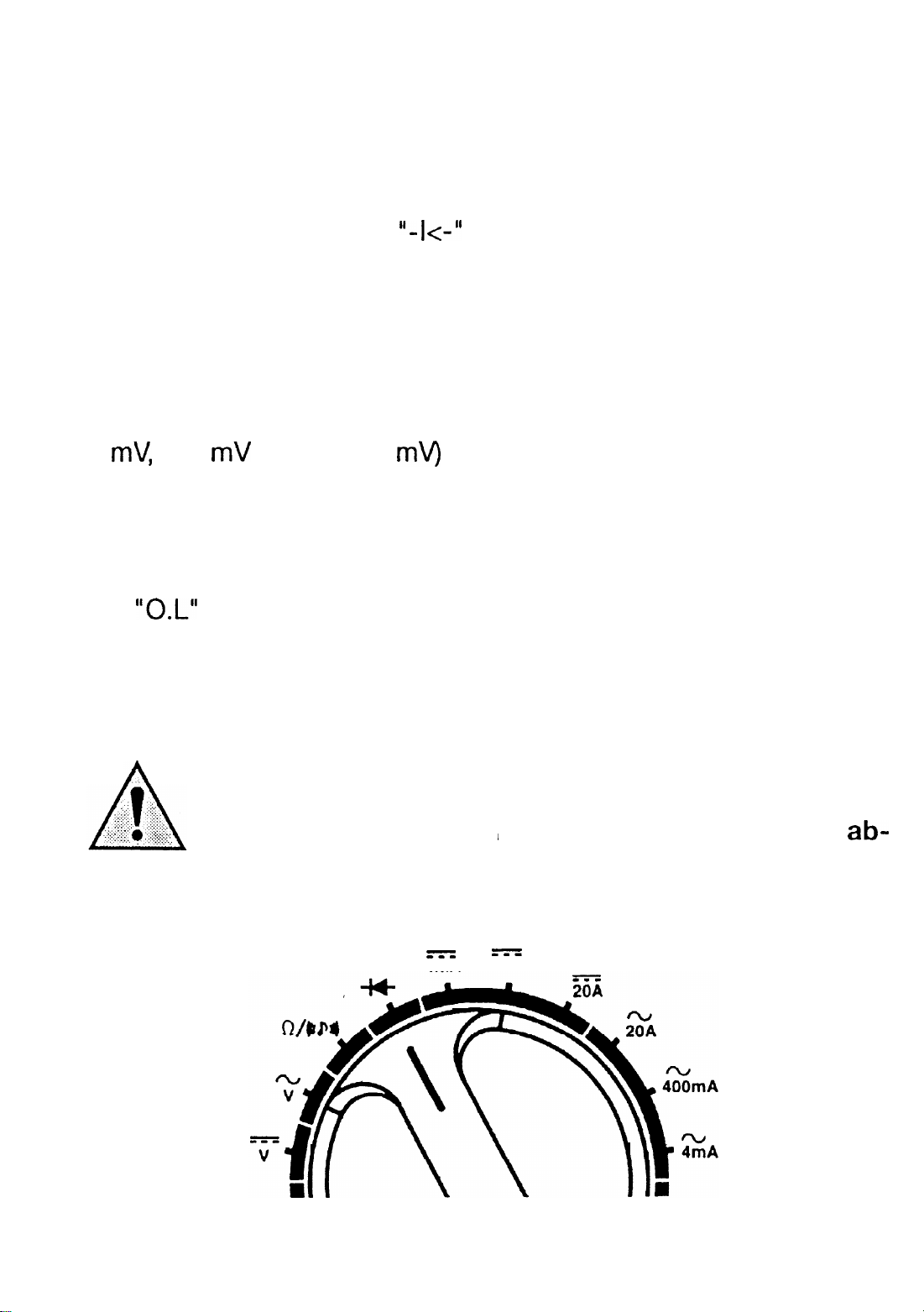
Rotary switch (= measuring function switch) for setting the
different operations (voltage measurement, current measure-
ment, etc.).
20 A input
5
This measuring input is protected with a 20 A fuse and is suita-
ble for DC and AC currents up to max. 20 A (max. 30 s
on with 15 minute pause between measurements).
6
This input is for measuring DC and AC currents up to 400
max. (protected with a quick-blow 800mA fuse)
push button
= captures the measured value.
push button
and
7
COM
V-Ohm-(+) input socket (= positive connection)
8
Multifunction LCD display
9
Analogue
10
Bar graph sub-graduations
11
Overload display
12
When
unds, this means overflow =
nal during resistance measurement, diode test or temperature
measurement).
input socket (COM or negative connection)
greatest indication: 3999) with
appears in the display and an acoustic signal so-
range exceeded (no acoustic sig-
Attention!
Observe the maximum input levels.
37
Page 7

Range Hold
Range hold means the measurement range is not switched au-
tomatically (auto range), but by hand, manually
14
15
16
AC
II
17
18
II
= Battery symbol
Data Hold
diode test
symbol for acoustic continuity test
symbol for alternating voltage or current
= minus sign, or symbol for negative polarity
If this symbol appears in the display, the battery must be chan-
ged
19 Various units of measurement
Contents
Introduction
Intended use
Operating elements (fold-out page)
Contents
Safety instructions
Presentation
Handling, putting into service
Performing measurements
Disposal
Rectification of faults
Service and calibration
Technical data and measurement tolerances
. . . . . . . . . . . . . . . . . . . . . . . . . . . . . . . . . . . . . . . . . . . . . . . . . . . . . . . . . . . . . . . . . . . . . . . . . . . . . . . . . . . .
. . . . . . . . . . . . . . . . . . . . . . . . . . . . . . . . . . . . . . . . . . . . . . . . . . . . . . . . . . . . . . . . . . . . . . . . . . . . . . . . . . .
................................................
.........................................................................................
..........................................................................
....................................................................................
.........................................................
.............................................................
..........................................................................................
......................................................................
...................................................................
.................................
Page
35
36
37
38
39
42
43
50
60
60
61
62
38
Page 8
Safety information
Damage resulting from non-observance of this manual renders void
any claim under the guarantee! We accept no responsibility for
consequential damage.
We accept no responsibility for damage to property or injury to persons caused by improper operation or failure to
the safety
instructions. Such cases void the guarantee.
l This unit is constructed and tested in accordance with DIN 57
411 part
0411 part
safety precautions for electronic
measuring devices or IEC 1010-I and left the factory in sound,
technically-safe condition. To maintain this condition and to ensure safe operation, it is essential for the user to observe the safety instructions and warning notes which are contained in these
operating instructions. The following symbols should be ob-
served:
. .
.
.
Dangerous voltages! Danger to life!
CAT II
category II
•l
l
Current measurements may only be carried out in circuits which
are themselves fused at 16 A or in which no voltage greater than
250 VDCNACrms or powers greater than 4000 VA can arise. The
measuring instrument must not be used in installations of Over-
voltage Category III in accordance with IEC 664. The measuring
instrument and instrument leads are not protected against arcing
(IEC 101 o-2-031, Section 13 I Of
l
Measuring instruments and accessories are not toys and do not
01).
belong in the hands of children!
39
Page 9

In commercial facilities the accident-prevention regulations of
the Industrial Employers’ Liability Association for electrical systems and equipment must be observed.
In schools, training facilities, hobby and self-help workshops, the
handling of measuring instruments must be supervised responsi-
bly by trained personnel.
When effecting replacements, it must be ensured that only fuses
of the specified type and specified current rating are used. The
use of a repaired fuse or the bridging of the fuse holder is not
permitted. To change the fuses, disconnect the measuring in-
strument from the circuit being measured and switch it off. Re-
move all connected leads and test probes. Select a suitable
crosspoint screwdriver and carefully open the housing. Remove
the defective fuse(s) and replace with identical type(s) and nomi-
nal current ratings.
0.8 A, quick-blow, 250 V; usual description: F 0.8 A
usual description:
5 A/ 250 V.
250 V or
Having successfully changed the fuse(s), carefully close and
screw the case up once more, in reverse order.
Only put the measuring instrument into operation once again
when the case is securely closed and screwed up.
Take particular care when dealing with voltages greater than 25
VAC or greater than 35 VDC. Even at these voltages it is possible
to receive a lethal electric shock if electrical conductors are tou-
ched.
Therefore, first of all switch off the voltage source to be mea-
sured, connect the measuring instrument to the voltage source,
set the required measurement range on the unit and only then
switch on the voltage source.
After completing measurements, switch off the voltage source
and remove the test leads from the voltage source connecting
points.
40
Page 10
Before any voltage measurement, ensure that the measuring
instrument is not set to the current measuring range.
l
Before every change in measuring range, the test leads or adap-
ter must be removed from the object being measured.
l
Before each measurement check your measuring instrument and
test leads for damage.
l
For measurements, only use the test leads which are supplied
with the measuring instrument. Others should not be used.
l
To avoid electric shock, care should be taken during measure-
ment not to touch the test probes and the connections (points of
measurement), not even indirectly.
l The voltage between a chosen 4 mm socket of the unit and
ground may not exceed 500
l
The measuring instrument should not be used in areas or under
rms.
adverse environmental conditions in which inflammable gas, fumes or dust are present or can occur. For your own safety it is
essential to avoid the measuring instrument or its wiring becoming damp or wet. Avoid operation in the immediate vicinity of:
a) strong magnetic fields (loudspeakers, magnets)
b) electromagnetic fields (transformers, motors, coils, relays,
electromagnets, etc..)
c) electrostatic fields (charges/discharges)
d) transmission aerials or HF generators
l
Do not use the multimeter shortly before, during, or shortly after
a thunderstorm (lightning strike!
high energy overvoltages! Ensure without fail that the hands, shoes, clothing, floor and the
measuring instrument and its test leads, switches and components, etc. are dry.
l
If it can be assumed that safe operation is no longer possible,
then the unit must be switched off and protected against unintentional operation. It can be assumed that safe operation is no
41
Page 11

longer possible if:
the unit shows visible signs of damage,
the unit no longer functions and
after prolonged storage under unfavourable conditions or
after severe transportation stress.
Never switch the unit. on immediately after it has been brought
from a cold into a warm area. The resultant condensation water
could damage the instrument. Allow the instrument to come to
room temperature before switching it on.
P’resentation
This 3 %-digit multimeter with bar graph display has several spe-
cial features which provide a complete picture for many measuring
tasks:
The unit has an AUTO RANGE feature, such that with different
measurements the currently-correct measuring range is always set.
In addition, the DMM can be connected to a PC with an appropriate cable (available as an option) via the built-in interface at its top
end. After installation of the appropriate software onto the PC
(available as an option), communication between the digital
meter and the PC becomes possible.
The 3
to a maximum of 3 digits after the decimal point. The Digital
meter ME-42 can be used universally in hobby, educational and
(non-industrial) commercial applications, etc.
liquid crystal display (LCD) allows resolutions of up
42
Page 12

Handling, Putting into operation
A Installation of batteries
For the measuring instrument to function perfectly, it must be fitted
with a
display, the batteries must be replaced.
Disconnect the unit from the circuit being measured,
remove the measuring leads from the measuring instrument,
switch it off and
with a suitable crosshead screwdriver, unscrew the fixing screws
in the lower part of the case at the centre top, bottom left and
bottom right.
Now carefully remove the cover.
Remove the used battery now revealed from the battery compartment,
disconnect it from the connecting clips and
battery. When the change-battery symbol appears in the
changing batteries
as follows:
replace the battery with a new one of the same type.
After successfully replacing the battery place it in the battery
compartment and carefully close this once more.
When closing the battery compartment, take care that the
red/black connecting clip leads do not become trapped.
Do not in any event operate the measuring device
when opened! Danger to life!
Do not leave used batteries in the unit, because
even leak-proof batteries can corrode and thereby
release chemicals, which are both damaging to
health and can destroy the battery compartment.
Used batteries are to be treated as waste requiring
special handling and must therefore be disposed of
without harming the environment. Special collection
containers are provided for this purpose by specia-
list dealers and in scrap yards.
43
Page 13

B Connecting the test leads
When taking measurements, only ever use the supplied instrument
leads or adapters/leads which can optionally be obtained for the
DMM and consequently are matched to it. Before connecting, always check the condition of the connecting plug and test probes
and check the insulation for damage.
The supplied connecting leads are suitable for voltages up to 1000
V max. The Digital Multimeter ME-42 is designed for voltages to
1000 VDC max. or 750 VAC rms max. Take particular care when
dealing with voltages greater than 25 V AC or 35 V DC.
. . . .
.
. .
. . .
Never exceed the maximum input levels, because
otherwise damage to the measuring instrument can
endanger life.
C Putting into operation
C 1 Basic setting
Note!
The following text contains numbers in brackets. These num-
bers relate to the description of the operating elements at the
beginning of these instructions.
Press the ON button (1). To select a type of measurement, turn the
rotary switch to the required position.
The built-in acoustic transducer sounds both during continuity
testing below 50 Ohm and when the measuring range is exceeded
(except during
ode testing).
44
resistance measurement/continuity testing and
Page 14

2 Button assignments
The “ON/OFF” button (1) switches the instrument both on and
off: press the button once and the unit will be switched on; press
it a second time and it will be switched off.
In addition a so-called Auto Power Off circuit is incorporated
which automatically switches the instrument off after approx. 15
minutes, to conserve energy.
The display becomes visible again when the instrument is (mechanically) switched off and on again via the “ON/OFF” switch
(2)
Using this function, changing measured values can be held for a
report. If the “D-H“ is pressed once, the measured value is “fro-
Press the button “D-H” again and the display returns to the
instantaneous measurement.
(3) On pressing this button once, the symbol “R-H” (for
Range Hold) appears in the display and the function “Auto Range” (= automatic range changing) is no longer active. Each time
this button is pressed, with voltage measurement the measurement range is increased and with resistance measurement the
range is decreased. The change of range can be seen on the one
hand from the change of unit of measurement and on the other
hand from the position of the decimal point. To return to automatic range change, press the “R-H” button for longer than approx.
1 s. As a result, the symbol “R-H” disappears from the display.
3 Connector and socket configuration
20 A socket
or AC current measurements (up to 20 A maximum!), the
red test lead must be pluaaed in here.
45
Page 15

:
Attention!
The measuring function switch must not on any
count be positioned on voltage measurement
during current measurement.
b)
socket
For DC or AC current measurement up to 400
maximum, the
red test lead must be plugged in here when the measurement
function switch (4) is set either to 4mA or 400mA during current
measurement.
c) COM = Common socket
The black test lead must be plugged in here for all measure-
ments except transistor or temperature measurement (common
socket means minus or
or earth socket)
d) V/Ohm socket
The red measuring lead must be plugged ‘into this socket to
carry out voltage, frequency or resistance measurements, continuity checks and diode tests.
e) Measuring function switch (4) or rotary switch
Attention!
The measuring function switch must not on any
.
count be moved during measurement, as this can
damage the measuring instrument (separation arcing) and as a result the user may be endangered in
the case of voltages greater than 25
or 35
VDC.
Arranged in a half circle, the different measuring ranges can be se-
lected by turning the switch:
DC voltage measurement (auto range)
46
Page 16

= AC voltage measurement (auto range)
Ohm ((+)) = Continuity testing and resistance measurement (auto
range)
-<-
= Diode test (no auto range)
= DC current measurement to 4
max. (no auto
range
DC current measurement to 400
=
max. (no auto
range)
= DC current measurement to 20 A max. (no auto
range)
= AC current measurement to 20
max. (no auto
range)
= AC current measurement to 4
max. (no auto
range)
= AC current measurement to 400
max. (no auto
range)
C 4 Display
explanation and symbols
a) Digital Anzeige
The display can indicate up to “3999” and (with negative volta-
ges or reversed polarity) the polarity is automatically indicated
There are also three decimal point positions.
b) Analogue bar graph
The analogue bar graph consists of 42 segments. It has a somewhat higher measuring speed than the digital display. This allows
measured value trends to be more easily recognised than with an
analogue multimeter, but without its mechanical disadvantages
(damping of the measuring unit).
If the measurement range is exceeded, then
for overload,
is displayed. The arrow on the display to the right of the bar
graph flashes.
47
Page 17

C 5 Operating modes, display details and symbols
a) Diode test
The value displayed during diode test is the forward voltage at
the approx. 1
test current. The measuring range here is 0 to
approx. 2.0 V.
b) Continuity testing
In continuity testing, the continuity of voltage-free leads, plug-in
connections or fuses can be checked both acoustically and opti-
cally. An acoustic signal sounds where the resistance is lower
than 50 Ohm.
c) Negative polarity
When the test leads are reversed or with negative polarity, a
sign appears in front of the measured value.
d) “D-H” Data Hold
e) “R-H” (= Range Hold = manual range selection)
After this button is pressed once, the symbol “R-H” (for Range
Hold) appears in the display and the function “Auto Range’ (=
automatic range changing) is no longer active. Each time this
button is pressed, with voltage measurement the measurement
range is increased and with resistance measurement the range is
decreased. The change of range can be seen on the one hand
from the change of unit of measurement and on the other hand
from the position of the decimal point. To return to automatic
range change, press the “R-H” button longer than approx. 1 s.
As a result, the symbol “R-H” disappears from the display.
Attention!
:
ii..:
. . . . . . . . .
. . .
This special function is only possible (only
ble) during DC and AC voltage measurement and
during resistance measurement.
48
Page 18

“Change battery” indicator
An alkaline
approx. 100 hours. About 8 hours before the battery becomes
empty, the “change battery” indicator appears in the display. A
battery check is performed in between each individual measu-
ring cycle.
remaining symbols indicate the various units of measurement:
AC
DC
V
A
= AC value
= DC value
= millivolt (exp.-3)
= Volt
= milliampere (exp.-3)
= ampere
=
battery in this measuring device lasts on average
(exp.3)
=
(exp.6)
D Positioning during use
Always operate the multimeter with the digital display is upwards
so that the liquid crystal display (LCD) can be read. There is a fold-
out bracket on the rear of the unit for better readability in the
upright position.
49
Page 19
Performing measurements
A DC voltage measurement
Attention!
. . . . . . .
. .
.
.
. . .
. .
For the measurement of DC voltage proceed as follows:
Connect the red test lead to the V/Ohm socket and the black
test lead to the COM socket.
2. Set the rotary switch (4) to
surement mode. The “Auto Range” feature matches the measurement input automatically to the DC voltage present, i.e. the
required measurement range is selected automatically.
Never exceed the maximum permissible input
vels, not even when measuring superimposed di-
rect voltages (e.g. ripple voltages): 1000 VDC max.
Do not touch any circuits or circuit components
when measuring voltages higher than 25 V AC rms
or 35 V DC.
This selects the DC voltage mea-
3. Connect the test probes to the test object (load, circuit, etc.).
4. The respective polarity of the measured value is shown together
with the present measured value.
The equals
a
sured voltage is negative (or the test leads are reversed).
Notes!
Due to the fact that the measurement input is very sensitive, it
may be that certain measured values (“phantom measured values”) are displayed even with test leads unconnected (not
connected to a circuit). This “manifestation” is normal and disappears as soon as a measurement is performed.
appears in front of the DC voltage measured value, the mea-
sign shows an input resistance of IO
When
50
Page 20
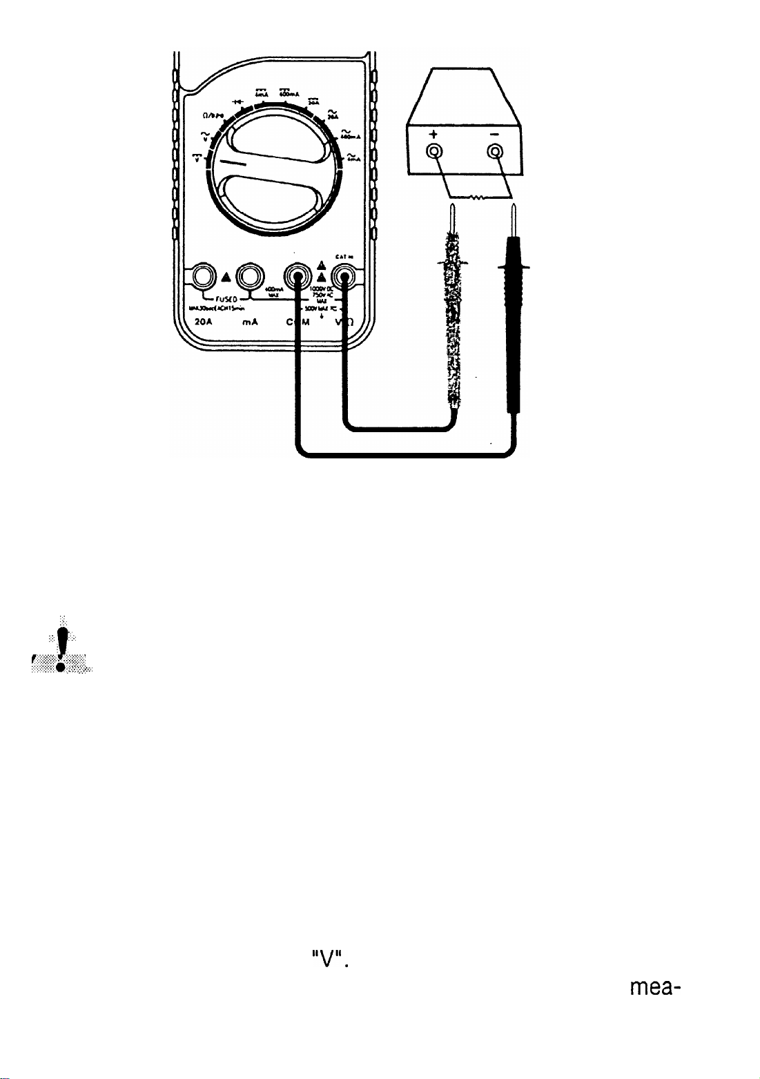
B AC voltage measurements
. .
Attention!
. .
A
For the measurement of AC currents proceed as follows:
1. Connect the red test lead to the V/Ohm socket and the black
2. Set the rotary switch (4) to
. . . . . . .._.. . . . . .
test lead to the COM socket.
surement mode. The “Auto Range” feature matches the
Never exceed the maximum permissible input le-
vels, not even when measuring superimposed di-
rect voltages (e.g. ripple voltages): 750 VAC rms
max.
Do not touch any circuits or circuit components
when measuring voltages higher than 25 V AC rms
or 35 V DC.
This selects the AC voltage mea-
51
Page 21

surement input automatically to the AC voltage present, i.e. the
required measurement range is selected automatically.
3. Connect the test probes to the test object (load, circuit, etc.).
4. The respective polarity of the measured value is shown in the
display, together with the present measured value.
The AC voltage range
input resistance of
Notes!
Due to the fact that the measurement input is very sensitive, it
may be that certain measured values (“phantom measured values”) are displayed even with test leads unconnected (not
connected to a circuit). This “manifestation” is normal and disappears as soon as a measurement is performed.
IO
in parallel with
20
(AC-coupled).
,
C DC current measurement
To measure DC current, proceed as follows:
1. Connect the black test lead to the COM socket and the red test.
lead to the
measured, or with the 20 A socket if currents between 400
socket if currents up to max. 400
are to be
and 20 A max. are to be measured..
2. Position the rotary switch to current measurement (4mA or =400
or
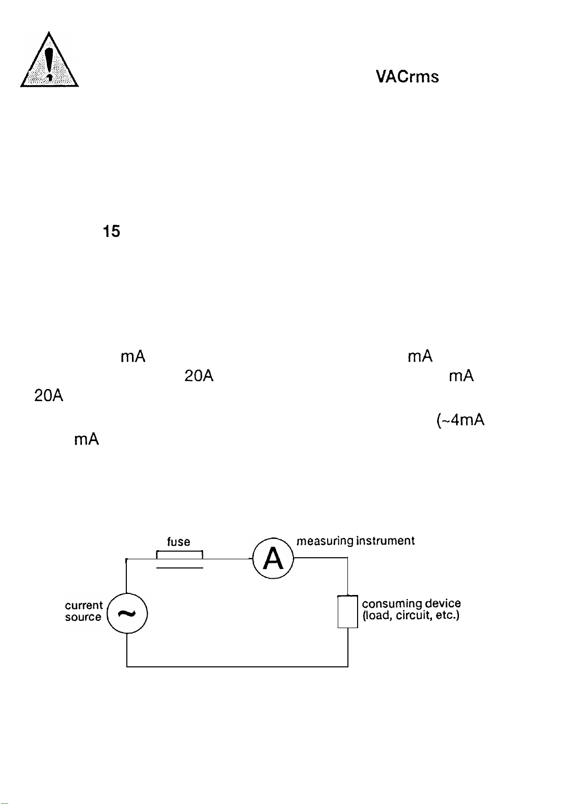
3. Connect the test leads in series with the object
(see following illustration).
52
A).
be measured
Page 22
Attention!
Do. not measure any currents in circuits in which
voltages greater than 250 VDC or
can occur, to avoid damaging the measuring device and
endangering life as a result. Never measure currents over 20 A. Measure only in circuits themselves
fused at 16 A and in which no power greater than
4000 VA can occur.
Measurements of currents at 20 A may be for 30 s
duration max. and be carried out only at intervals of
minutes (shunt cooling phase).
D AC current measurement
To measure AC currents, proceed as follows:
1. Connect the black test lead to the COM socket and the red test
lead to the
measured, or to the
socket if currents up to max. 400
socket if currents between 400
are to be
and
max. are to be measured.
2. Position the rotary switch to current measurement
-400
or -20 A).
or
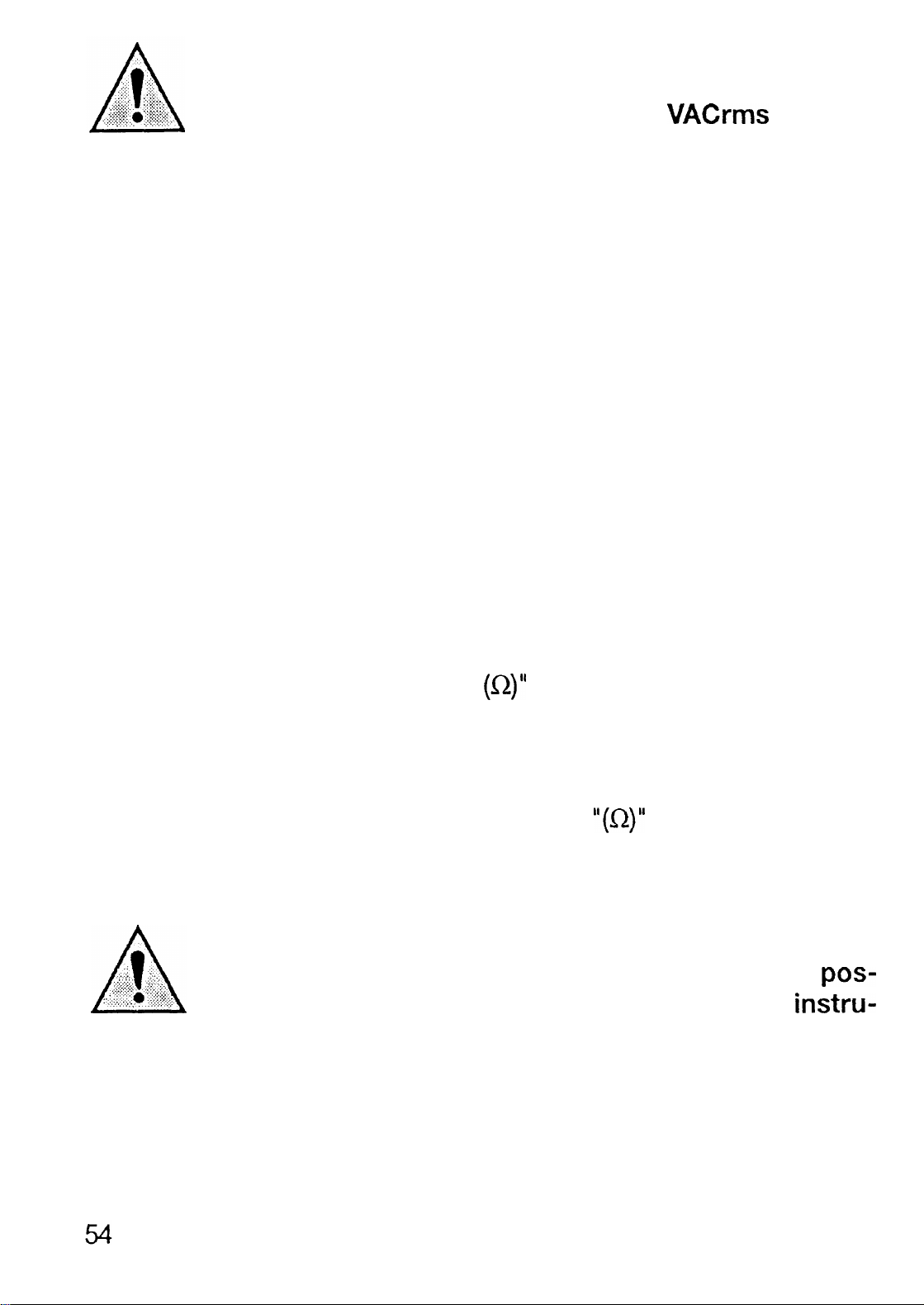
3. Connect the. test leads in series with the object to be measured
(see following illustration).
53
Page 23
Attention!
Do not measure any currents in circuits in which
voltages greater than 250 VDC or
cur, to avoid damaging the measuring device and
endangering life as a result. Never measure cur-
rents over 20 A. Measure only in circuits themselves
fused at 16 A and in which no power greater than
4000 VA can occur.
Measurements of currents at 20 A may be for 30 s
duration maximum and be carried out only at intervals of 15 minutes (shunt cooling phase).
can oc-
E Continuity testing
With this function, voltage-free wiring, fuses, circuits, etc. can be
acoustically tested for continuity. For this measurement, proceed
as follows:
1. Connect the black test lead to the COM socket and the red test
lead to the V/Ohm socket.
2. Set the rotary switch to “Ohm
stance measurement). Then connect the test probes to the completely voltage-free test object.
3. If the continuity resistance is less than some 50 Ohm, then an
acoustic signal sounds and the symbol
tom left in the display
Attention!
.
Do not measure charged capacitors because a
sible discharge may damage the measuring
ment.
(= continuity testing or resi-
appears at the bot-
Page 24
F Resistance measurement
Attention!
. . . . . . .
A
To perform a resistance measurement, proceed as follows:
1.
Connect the black test lead to the COM socket and the red test
lead to the V/Ohm socket.
. .
Ensure that all circuit elements, circuits and
ponents and other objects to be measured are ab-
solutely voltage-free.
Set the rotary switch to “Ohm
2.
automatically matches the measuring input to the resistance present, i.e. the required measuring range selects itself automatical-
3.
Check the test leads for continuity by connecting both test probes together. As a result a resistance value of about 0.1 to 0.2
Ohm appears (= resistance of the test leads).
4.
Now connect the measuring probes to the object to be measured. If the expected resistance of the object to be measured
less than about IO Ohm, the resistance of the test leads must be
subtracted from the measured value.
Notes!
When resistance measurements are performed, ensure that the
measurement points which are to be touched with the test pro-
The “Auto-Range” feature
bes are free from dirt, oil, solder flux or similar. Such conditions can distort the measured value.
With resistances greater than approx. 1
the display will take some time to “stabilise”. As soon as
appears in the display and an arrow appears at the right-hand
end of the bar graph, the measurement range has been excee-
ded, or the measurement path is open-circuit.
it can be that
55
Page 25
G Diode test
To measure diodes or semiconductor paths, proceed as follows:
I. Connect the black test lead to the COM socket and the red test
lead to the V/Ohm socket.
2. Set the rotary switch to
and connect the test probes to the
object to be measured, a voltage-free semiconductor path, with
the red test probe to the anode and the black test probe to the
cathode (which is usually indicated by a coloured ring, spot or similar).
If you test a diode path in the conducting direction, a voltage of
approx. 0.25 V (germanium) or 0.7 V (silicon) up to’2.0 V (or 250
700
up to 2000
will be measured provided that the
diode path is not defective.
If the test leads are interchanged, i.e. red to the cathode and
black to the anode, then the non-conducting direction of the di-
ode path is checked.
If
is displayed, then the diode is in good condition. If on
the contrary a voltage value is indicated, then either the object to
be measured is incorrectly connected or is defective.
.
Attention!
During diode testing,
any circuit into which
solutely voltage-free.
be discharged.
4mA
make sure that
it may possibly
All capacitors
400mA
the diode and
be built is
present must
56
Page 26

BLACK PROBE
Cathode Mark
H Using the analogue bar graph
The bar graph is easy to operate and understand. It is comparable
with the pointer of an analogue measuring instrument without its
mechanical disadvantages. It is particularly suitable for fast-changing measured signals, for which the digital display is too “slow”.
Hence, trends in a measured value change can be quickly recognised and evaluated. The measuring rate here is approx. 2-3 measurements per second.
I Using the multimeter in connection with a com-
puter
An extensive Windows software package (floppy disk and interface
lead) for connection/communication with a computer can be supplied as an option.
a) Connection .
With the computer switched off, connect an RS 232 interface lead
(which can be optionally supplied with the software) both to the
multimeter (in the direction of the arrow, remove the cover at the
top end of the unit) and to a serial interface of the switched-off
computer (also see the illustration)
57
Page 27

Now switch on the measuring device and the computer.
b) Using the optional software (not supplied with the multimeter)
The MS DOS program is called METEX and is stored under GRA-
PHIC on a floppy disk. The Windows program is called Scopeview
and is stored under SCOPE on another floppy disk.
Use of the MS DOS software is described below:
Notes!
The following instruction(s) presuppose basic knowledge of
the various MS DOS commands and an available hard disk. If
the user has insufficient or no basic knowledge of MS DOS
commands, the MS DOS manual must be consulted concer-
ning software installation. In addition, a VGA monitor (+ VGA
card in the computer) is required to operate the software.
Insert the floppy disk into the appropriate disk drive (A or B or si-
milar).
2. Open a new directory: md\ METEX (Enter)
3. Then call this directory: cd\ (Enter
4.
Copy all GRAPHIC subdirectories into the directory METEX using
Copy a:\GRAPHIC c:
58
Page 28

5. .
Note!
To start the program, type METEX and confirm with Enter.
To stop the program or should errors occur,
boot” the
computer
The use of Windows software is described below:
Attention!
. . . . . .
. . .
.
The following steps presuppose basic knowledge of
MS Windows. In case of difficulty, study the Win-
dows manual concerning the use of WINDOWS.
Windows Version 3.1 or higher and a VGA monitor
(display) is required to run this software.
Start your computer and activate Windows.
2.
Insert the floppy disk into the appropriate disk drive (A or
3.
In Program Manager, open the file window and click “Run“ with
the mouse. As a result, a dialog box with a command line ap-
pears.
Type the following at the flashing cursor:
4.
a:\scope\setup and press Enter, when the diskette is in drive a
b:\scope\setup and press Enter, when the diskette is in drive b
5.
Follow the on-screen directions to complete the installation.
To start the program, with the left mouse button double-click the
6.
SCOPEVIEW icon and then follow the on-screen instructions.
Pay attention also to the
file on the diskette for re-
marks concerning operation.
The
must be observed if you aenerate your own soft-
ware:
59
Page 29

A data format is 14 bytes long. The sequence is as follows:
BYTE
Example 1 D C
Example2 OH
Program example in BASIC for easy reading of the multimeter:
IO OPEN
20 A$ =
30 PRINT #2,A$
40
50 PRINT
60 CLOSE
70 END
Specification for data transfer (communication parameters):
Transfer rate :
Character code :
Parity
Stop bits
=
3 . 9 9 9
3 l 999MOhmCR
(14,
600 baud
.
.
keine
.
2
.
V CR
AS
ASCII
Disposal
If despite a good
timeter does not function or is no longer repairable, then it must be
disposed of in accordance with applicable statutory regulations.
battery supply and intact fuses the digital
Rectification of faults
With the Digital Multimeter ME-42 you have acquired a product
built to the latest technological standards. However, problems or
faults can arise. Because of this, the following describes how some
of these problems can be resolved by the user relatively easily; observe the safety information without fail!
60
Page 30

Fault
Possible cause
No current
ment possible
No display when
unit switched on
::
.
Attention!
Except where this can be performed manually, live
parts may be exposed when opening covers or removing components. Connecting parts may also
be live. Before any adjustment, maintenance, repair or exchange of parts or assemblies requiring
Fuses for the current ranges O.K.?
Are the test leads making good contact in
their sockets?
Are the test leads in the A or uA/mA
socket and COM?
Is the battery exhausted?
Has the measuring instrument switched
itself off after 15 minutes of no activity?
opening of the unit, the unit must be disconnected
from all
cuits. If adjustment, maintenance or repair is sub-
sequently required on the opened unit while it is Iive, these must only be performed by a specialist
familiar with the associated hazards and relevant
regulations (VDE-0100, VDE-0701, VDE-0683).
Capacitors in the unit may still be charged even
when it has been isolated from all voltage sources
and circuits.
sources and measurement cir-
Maintenance and calibration
To guarantee the accuracy of the multimeter over a long period of
time, it should be calibrated once annually. The calibration can be
carried out economically by our “Service 2000” calibration centre.
61
Page 31

Changing a fuse is described under 3. Safety requirements. Changing the battery can be found under 5.1.
To clean the unit or the display window, use a clean, lint-free, antistatic, dry cleaning cloth.
Attention!
. . .
.
Do not use any carbonaceous cleaning agents or
petrol, alcohol or similar for cleaning. They can
attack the surface of the measuring instrument. Additionally, the fumes are explosive and endanger
health. Do not use any sharp-edged tools, screwdrivers, metal brushes or similar for cleaning.
Technical data and measurement tolerances
Technical data
Display.. . . . . . . . . . . . . . . . . . . . . . . . . . . . . . . . . . . . . . .
. .
Maximum rate of measurement:
Maximum AC/DC input current:
Operating temperature
Storage temperature
Relative
humidity . . . . . . . . . . . . . . . . . . . . ..:
.............
................
3
LCD display up to
3999, with automatic polarity indicator
1.5 measurements per second
20 A for 30s maximum with a
cooling phase of at least 30 minu-
tes until the next current mea-
surement
0°C to + 40°C (32°F to 104°F)
.
-10°C to
.
0 up to 75
(14°F to 122°F)
non-condensing
Temperature for
guaranteed
Battery type
accuracy . . . . . . . . . . . . . . . . .
. . . . . . . . . . . . . . . . . . . . . . . . . . . . . . .
.
1 x 9 V battery, Typ
Weight
. . . . . . . . . . . . . . . . . . . . . . . . . . . . . . . . . . . . . . .
Dimensions (L X W X H) . . . . . . . . . . . . .
.
350g
187x81
62
K
1604 or
(with battery)
Page 32
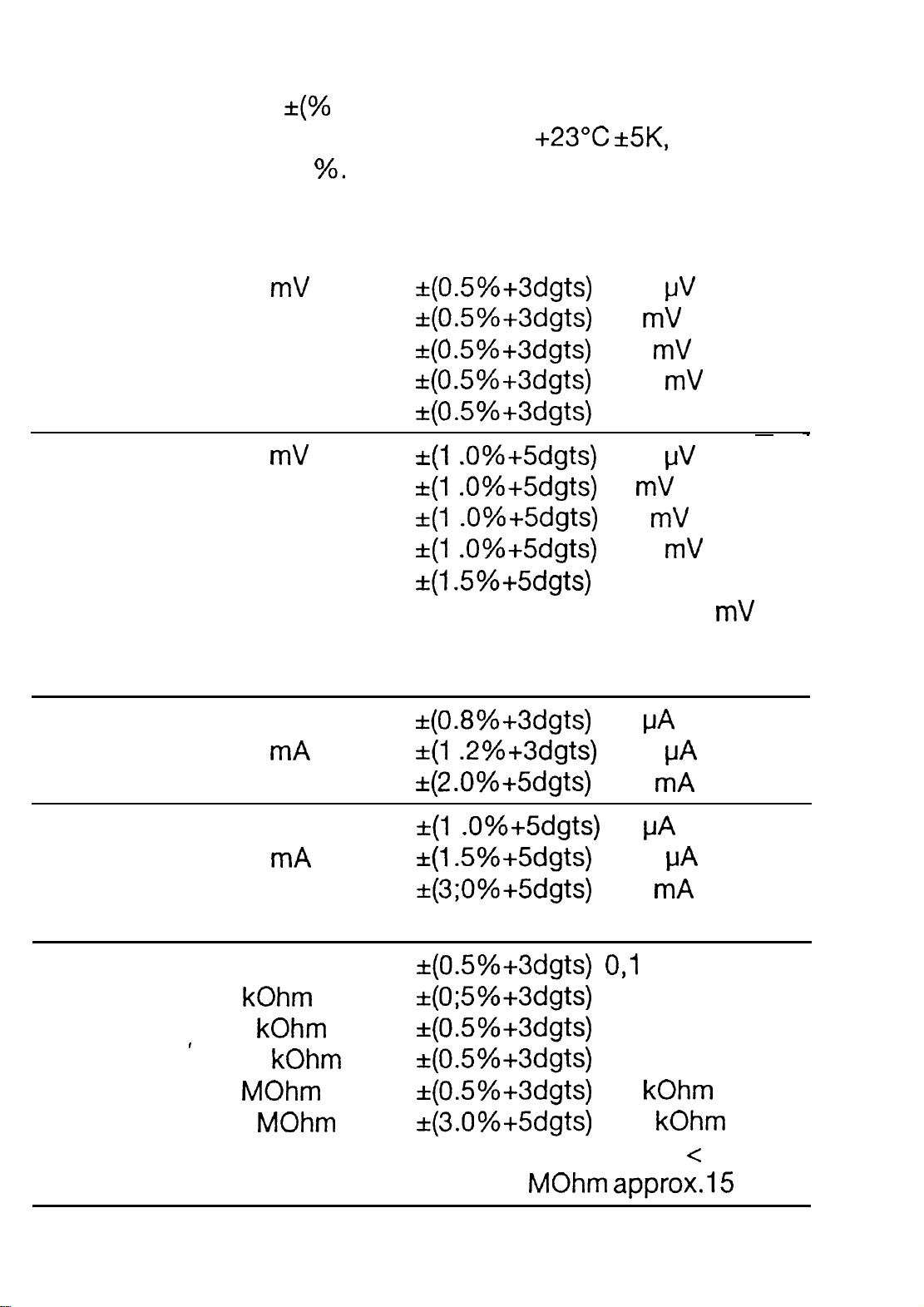
Measurement tolerances
Accuracy specified in
Accuracy over 1 year at a temperature of
humidity of less than 75
Operating
mode
DC
voltage
AC voltage
Measurement Accuracy
range
400
4 v
40 v
400 v
1000 v
400
4v
40 v
400 v
750 v
of reading + number of digits)
The warm-up time is 1 minute.
Resolution
100
1
IO
100
1 V
100
1
IO
100
1 V
at a relative
Valid for frequency range from 40 Hz to 100 Hz in the 400
range
Valid for frequency range from 40 Hz to 400 Hz in other ranges
DC current
AC current
Valid for frequency range from 40 Hz to 400 Hz in all three ranges
Resistance
4mA
400
20 A
4mA
400
20 A
400 Ohm
4
40
400
4
1
100
IO
1
100
IO
Ohm
1 Ohm
IO Ohm
100 Ohm
I
40
Measurement voltage at open circuit being measured : c 1.2 V
Time for indication stabilisation:
40
IO
s
63
Page 33
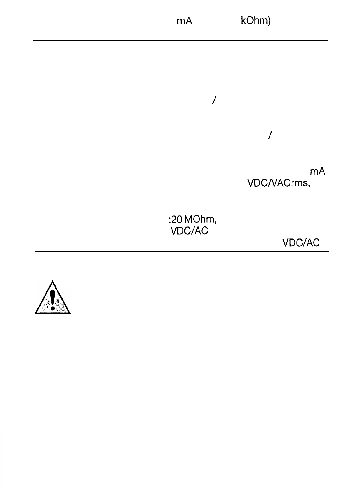
Diode test
Test current 1.5 mA max. (at 1
Test voltage 2.0 VDC max.
Continuity test:
acoustic signal with resistances
lower than 50 Ohm
Maximum input quantities, overload protection
Voltage measurement
Current measurement
: 1000 VDC or 750 VAC
: 20 A AC
DC in the A range, 30
seconds duration max. with an additional cooling phase of at least
15 minutes, 250 VDC
maximum
Overload protection
: Super-fast 15 A 250 V fuse (size: 6
x 30mm) 200mA AC/DC in the
.
Overload protection
range, max. 250 VDCNACrms,
: Fast 0.8 A 250 V fuse (size: 5 x 20
mm)
Resistance measurement
MOhm, overload protection 250
VAC rms
Diode test/continuity test : overload protection 250
Attention!
. .
l
. .
.
Exceeding the maximum permissible input values
under adverse conditions will lead to damage to the
measuring instrument or to the life of the user being
endangered.
64
Page 34
100%
D
Impressum
Chlorfrei
gebleicht.
100%
Bleached
without
chlorine.
Diese Bedienungsanleitung ist eine Publikation der Conrad Electronic
vorbehalten. Reproduktionen jeder Art, z. B.
kopie, Mikroverfilmung, oder die Erfassung in elektronischen Datenverarbeitungsanlagen,
der schriftlichen Genehmigung des Herausgebers.
Nachdruck,
Diese Bedienungsanleitung entspricht dem technischen Stand
in
Copyright 1999 by Conrad Electronic
auszugsweise, verboten.
Drucklegung. Anderung
und Ausstattung vorbehalten.
Printed in Germany.
Imprint
These operating instructions are published by Conrad Electronic
Hirschau/Germany
No reproduction (including translation) is permitted in whole or part e.g. photocopy, microfilming or storage in electronic data processing equipment, without the express written
consent of the publisher.
The operating instructions reflect the current technical specifications at time of print. We
reserve the right to change the technical or physical specifications.
Copyright 1999 by Conrad Electronic
Printed in Germany.
100%
100%
F Note de
Cette notice est une publication de la
droits reserves, y
traduction. Toute reproduction, quel que
exemple photocopies microfilms ou saisie dans des traitements de texte electronique est
soumise
Impression,
Cette notice est
une autorisation
interdite.
la reglementation en vigueur
techniques et conditionnement soumis
Copyright 1999 par Conrad Electronic
modifications sans aucun
Conrad Electronic
de
en Allemagne.
le type, par
de I’impression.
NL
Deze gebruiksaanwijzing is een publikatie van Conrad Electronic Ned
rechten, inclusief de
fotokopie, microfilm of opgeslagen in een geautomatiseerd gegevensbestand,
schriftelijke toestemming van de uitgever.
Nadruk, ook in uittreksel, verboden.
Deze gebruiksaanwijzing voldoet
gen in techniek en uitrusting voorbehouden.
voorbehouden. Reprodukties van welke aard dan ook,
met
de technische eisen bij het ter perse gaan.
Copyright 1999 by Conrad Electronic Ned
Printed in Germany.
‘1
 Loading...