

Page 1
BEDIENUNGSANLEITUNG
NOTICE DEMPLOI
OPERATING INSTRUCTIONS
D
F
GB
100%
RecyclingPapier.
Chlorfrei
gebleicht.
Conrad im Internet: http://www.conrad.de
100%
recycling
paper.
Bleached
without
chlorine.
100%
papier
recyclé.
Blanchi
sans
chlore.
D
Impressum
Diese Bedienungsanleitung ist eine Publikation der Conrad Electronic GmbH.
Alle Rechte einschließlich Übersetzung vorbehalten. Reproduktionen jeder Art, z. B.
Fotokopie, Mikroverfilmung, oder die Erfassung in elektronischen Datenverarbeitungsanlagen, bedürfen der schriftlichen Genehmigung des Herausgebers.
Nachdruck, auch auszugsweise, verboten.
Diese Bedienungsanleitung entspricht dem technischen Stand bei Drucklegung.
Änderung in Technik und Ausstattung vorbehalten.
© Copyright 2003 by Conrad Electronic GmbH. Printed in Germany.
GB
Imprint
These operating instructions are published by Conrad Electronic GmbH, KlausConrad-Str. 1, 92240 Hirschau/Germany
No reproduction (including translation) is permitted in whole or part e.g. photocopy,
microfilming or storage in electronic data processing equipment, without the express
written consent of the publisher.
The operating instructions reflect the current technical specifications at time of print.
We reserve the right to change the technical or physical specifications.
© Copyright 2003 by Conrad Electronic GmbH. Printed in Germany.
F
Note de l´éditeur
Cette notice est une publication de la société Conrad Electronic GmbH, Klaus-Conrad-Str. 1,
92240 Hirschau/Allemagne.
Tous droits réservés, y compris traduction. Toute reproduction, quel que soit le type, par
exemple photocopies, microfilms ou saisie dans des traitements de texte electronique est
soumise à une autorisation préalable écrite de l`éditeur.
Impression, même partielle, interdite.
Cette notice est conforme à la règlementation en vigueur lors de l´impression.
Données techniques et conditionnement soumis à modifications sans aucun préalable.
© Copyright 2003 par Conrad Electronic GmbH. Imprimé en Allemagne.
S01-0703
F
GB
D
PC-ATX-Schaltnetzteil 550W
"FSP550-60PLN"
Seite 3-15
PC-ATX Switching Power Supply
550W "FSP550-60PLN"
Page 17-29
Bloc dalimentatio secteur ATX
pour ordinateur 550W
"FSP550-60PLN"
Page 31-43
Version 07/03
Best.-Nr. / Item-No. / No de commande: 99 85 34
Page 2
2
D
Diese Bedienungsanleitung gehört zu diesem Produkt.Sie enthält wichtige Hinweise zur
Inbetriebnahme und Handhabung. Achten Sie hierauf, auch wenn Sie dieses Produkt an Dritte
weitergeben.
Heben Sie deshalb diese Bedienungsanleitung zum Nachlesen auf!
Eine Auflistung der Inhalte finden Sie in dem Inhaltsverzeichnis mit Angabe der entsprechenden
Seitenzahlen auf Seite 4.
GB
These operating instructions belong with this product. They contain important information for
putting it into service and operating it. This should be noted also when this product is passed on to
a third party.
Therefore look after these operating instructions for future reference!
A list of contents with the corresponding page numbers can be found in the index on page 17.
F
Ce mode d'emploi appartient à ce produit. Il contient des recommandations en ce qui concerne
sa mise en service et sa manutention. Veuillez en tenir compte et ceci également lorsque vous
remettez le produit à des tiers.
Conservez ce mode d'emploi afin de pouvoir vous documenter en temps utile.!
Vous trouverez le récapitulatif des indications du contenu à la table des matières avec mention de la page
correspondante à la page 30.
Il en va naturellement de même pour tous les autres appareils qui sont raccordés à lordinateur, p. ex.
écran, scanner, haut-parleur etc.
Des appareils ne disposant pas de «véritables» interrupteurs de secteur (p. ex. de nombreux hautparleurs dordinateur, certains écrans ou tous les appareils munis dune prise dalimentation) peuvent
être mis hors tension de secteur à laide dun prise multiple pourvue dun interrupteur marche/arrêt.
En mode veille, le système complet de lordinateur peut absorber une énergie atteignant facilement
50W. Au bout dune journée, un kilowattheure (1 kWh) est déjà «consommé» inutilement et
transformé en chaleur.
Ainsi, lacquisition dune prise multiple pourvue dun interrupteur marche/arrêt est rentabilisée au bout
dun an déjà.
Si tous les éléments consommateurs dénergie (ordinateur, écran, imprimante etc.) sont mis
sous tension ensemble, il est possible que cette opération déclenche le coupe-circuit automatique
du circuit correspondant en raison de la puissance excessive du courant de déclenchement.
Si cest votre cas, mettez tout dabord linterrupteur de la prise multiple sous tension et ensuite
les appareils, un par un.
Pour éteindre, procéder dans le sens inverse, éteignez en premier les appareils et ensuite la
prise multiple.
existe aussi ledit «Power Manager», qui permet de mettre en marche et darrêter les prises
indépendamment des autres par lintermédiaire dun interrupteur placé à lavant. Ces «Power
Manager» sont installés p. ex. sous lécran.
Les imprimantes à jet dencre doivent être éteintes en premier avec linterrupteur de limprimante
avant de couper le courant de secteur via la prise multiple, par exemple.
Dans le cas contraire, limprimante ne peut amener la tête dimpression en position de garage
et les injecteurs de la tête dimpression peuvent donc sécher!
Certaines imprimantes devraient rester en permanence raccordées à la tension de secteur,
parce que, autrement, lors du retour de la tension (lors de la mise sous tension via la prise
multiple), elles effectuent une opération de nettoyage supplémentaire. Les coûts de cette
consommation inutile dencre dépassent souvent le montant dune économie dénergie.
Veuillez absolument respecter les limitations concernant la consommation maximale de courant des
différentes tensions de fonctionnement indiquées au point 10 de ce mode demploi (voir aussi le texte
imprimé sur le bloc dalimentation) !
Une surcharge entraîne la destruction du bloc dalimentation ! De plus, il existe le risque
dendommager les éléments qui consomment de lénergie, raccordés au bloc, comme la carte
mère, disque dur, etc.
Si votre carte mère est munie dune borne ATX 2.0 à 4 pôles, veuillez la raccorder avec la borne
correspondante du bloc dalimentation ATX pour ordinateur.
La borne sert à améliorer lalimentation des régulateurs à découpage (qui produisent du courant/tension
pour le processeur central) sur la carte mère et à décharger la ligne de +12V de la prise de courant ATX.
Cela sapplique aussi pour la fiche à 8 pôles.
43
Page 3
D
Einführung
Sehr geehrter Kunde,
wir bedanken uns für den Kauf dieses Netzteils.
Das Produkt ist EMV-geprüft und erfüllt die Anforderungen der geltenden europäischen und
nationalen Richtlinien. Die CE-Konformität wurde nachgewiesen, die entsprechenden Erklärungen
sind beim Hersteller hinterlegt.
Um diesen Zustand zu erhalten und einen gefahrlosen Betrieb sicherzustellen, müssen Sie als Anwender
diese Bedienungsanleitung beachten!
Alle enthaltenen Firmennamen und Produktbezeichnungen sind Warenzeichen der jeweiligen
Inhaber. Alle Rechte vorbehalten.
Bei Fragen wenden Sie sich an unsere Technische Beratung:
Deutschland: Tel. 0180/5 31 21 16 oder 0 96 04/40 88 47, Fax 0 96 04/40 88 48
E-Mail: tkb@conrad.de
Mo. bis Fr. 8.00-18.00 Uhr
Österreich: Tel. 072 42/20 30 60, Fax 072 42/20 30 66
E-Mail: support@conrad.at
Mo. bis Do., 8.00-17.00 Uhr, Fr. 8.00-14.00 Uhr
Schweiz: Tel. 0848/80 12 88, Fax 0848/80 12 89
E-Mail: support@conrad.ch
Mo. bis Fr. 8.00-12.00, 13.00-17.00 Uhr
Bestimmungsgemäße Verwendung
Das PC-ATX-Schaltnetzteil ist zum Einbau in ein entsprechendes PC-ATX-Gehäuse vorgesehen.
Es dient dort zur Stromversorgung von PC-Komponenten wie Mainboard, Festplatte, CD-ROM usw.
Das Mainboard muss über einen ATX-Stromanschluss verfügen.
Durch die hohe Leistung von max. 550W (bitte beachten Sie die technischen Daten!) können auch große
PCs mit zahlreichen Erweiterungen versorgt werden.
Eine andere Verwendung als zuvor beschrieben führt zu Beschädigungen dieses Produkts, außerdem ist
dies mit Gefahren wie z.B. Kurzschluss, Brand, elektrischer Schlag etc. verbunden. Das gesamte Produkt
darf nicht geändert bzw. umgebaut werden. Das Gehäuse darf nicht geöffnet werden. Die auf dem Produkt
befindlichen Aufkleber dürfen nicht beschädigt oder entfernt werden, ebenso dürfen keinerlei Schrauben
oder Befestigungen des Produkts gelöst oder entfernt werden.
342
(
jaune
)
(
noir
)
(
en rouge
)
(
noir
)
(
noir
)
(
noir
)
(
en rouge
)
(
noir
)
(
jaune
)
(
jaune
)
(
jaune
)
(
noir
)
(
jaune/noir
)
(
noir
)
(
jaune/noir
)
(
jaune/noir
)
(
jaune/noir
)
(
noir
)
(
noir
)
(
noir
)
b)Fiche 5.25"
c) Fiche 3.5"
d) Fiche ATX 2.0-12V à 4 pôles
e) Fiche ATX 12V à 8 pôles
12. Conseils & indications
Comme mentionné plus tôt, le bloc dalimentation est en mode veille une fois quil a été éteint à laide
du bouton «Power» du boîtier ATX.
Il est encore sous tension de secteur ! Par exemple, un téléviseur fonctionne de la même manière, vous
pouvez le mettre en mode veille à laide de la télécommande.
En mode veille, le bloc dalimentation «consomme» toujours du courant. Pour économiser de lénergie,
vous devriez éteindre le bloc dalimentation en vous servant de linterrupteur, si vous navez pas besoin
de votre ordinateur.
Page 4
Inhaltsverzeichnis
Seite
1 . Lieferumfang ........................................................................................................................................4
2 . Sicherheitshinweise .............................................................................................................................4
3 . Funktionsbeschreibung........................................................................................................................5
4 . Bedienelemente und Anschlüsse.........................................................................................................5
5 . Einbau..................................................................................................................................................6
6 . Handhabung ........................................................................................................................................8
7 . Wartung & Reinigung.........................................................................................................................10
8 . Entsorgung.........................................................................................................................................11
9 . Behebung von Störungen ..................................................................................................................11
10. Technische Daten..............................................................................................................................12
11. Anschlussbelegungen der Stecker ....................................................................................................13
12. Tipps & Hinweise ...............................................................................................................................14
1. Lieferumfang
Netzteil
Netzkabel
ATX-Adapterkabel (24pol. auf 20pol.)
Bedienungsanleitung
2. Sicherheitshinweise
Bei Schäden, die durch Nichtbeachtung dieser Bedienungsanleitung verursacht werden,
erlischt der Garantieanspruch. Für Folgeschäden übernehmen wir keine Haftung!
Bei Sach- oder Personenschäden, die durch unsachgemäße Handhabung oder Nichtbeachten der Sicherheitshinweise verursacht werden, übernehmen wir keine Haftung. In
solchen Fällen erlischt jeder Garantieanspruch!
Aus Sicherheits- und Zulassungsgründen (CE) ist das eigenmächtige Umbauen und/oder Verändern des
Produkts nicht gestattet.
Der Betrieb ist nur in trockenen Innenräumen zulässig.
Als Spannungsquelle darf nur eine ordnungsgemäße Netzsteckdose mit Schutzleiter des öffentlichen
Versorgungsnetzes verwendet werden.
Das Netzteil verfügt über einen Full-Range-Eingang (100-240V~, 50-60Hz).
Geräte, die an Netzspannung betrieben werden, gehören nicht in Kinderhände. Lassen Sie deshalb in
Anwesenheit von Kindern besondere Vorsicht walten.
In gewerblichen Einrichtungen sind die Unfallverhütungsvorschriften des Verbandes der gewerblichen
Berufsgenossenschaft für elektrische Anlagen und Betriebsmittel zu beachten.
In Schulen, Ausbildungseinrichtungen, Hobby- und Selbsthilfewerkstätten ist das Betreiben des Produkts
durch geschultes Personal verantwortlich zu überwachen.
4
41
(orange)
(orange)
(orange)
(orange/
brun)
(orange)
(orange)
(orange)
(
sait
)
(
vert
)
(
bleu
)
(
jaune
)
(
violet
)
(
gris
)
(
noir
)
(
en rouge
)
(
noir
)
(
en rouge
)
(
noir
)
(
en rouge
)
(
noir
)
(
noir
)
(
noir
)
(
en rouge
)
(
noir
)
(
sait
)
(
vert
)
(
bleu
)
(
jaune
)
(
violet
)
(
gris
)
(
noir
)
(
en rouge
)
(
noir
)
(
en rouge
)
(
noir
)
(
en rouge
)
(
noir
)
(
noir
)
(
noir
)
(
en rouge
)
(
noir
)
(
en rouge
)
(
noir
)
(
jaune
)
11. Configuration des fiches
a) Fiche ATX
Les couleurs des lignes indépendantes (p. ex. PS ON et Power OK) peuvent différer.
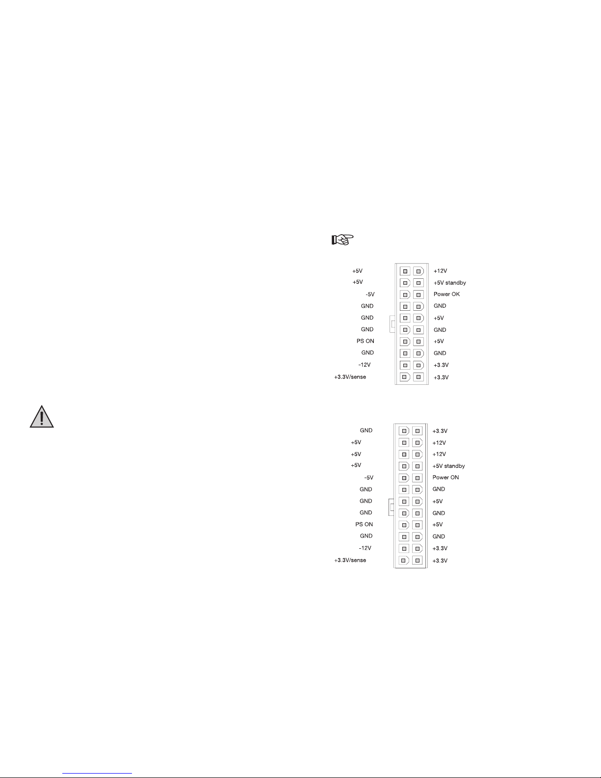
Version à 20 pôles :
Version à 24 pôles :
Page 5

3. Funktionsbeschreibung
Über die Netzspannungsbuchse wird das Netzteil mit Netzspannung/-strom versorgt. Das Netzteil verfügt
über einen Full-Range-Eingang (100-240V~, 50-60Hz).
Das PC-ATX-Schaltnetzteil wandelt diese Netzspannung in die intern vom Computer benötigten Gleichspannungen (+5V, +12V, -5V, -12V und +3.3V) um.
Ein eingebauter Lüfter führt überschüssige Wärme, die bei dieser Wandlung entsteht, nach außen ab.
Über den Netzschalter kann das Produkt ein- und ausgeschaltet werden.
Der Computer startet jedoch beim Einschalten des Netzschalters noch nicht. Sowohl Netzteil
als auch das angeschlossene Mainboard befinden sich erst im sog. "Standby"-Betrieb. Zum
Start des Rechners muss der Power-Taster auf der Frontseite Ihres ATX-Gehäuses kurz
gedrückt werden. Der Taster muss über ein Kabel mit dem entsprechenden Anschluss auf
Ihrem Mainboard verbunden sein (z.B. Anschluss "ATX-Power" o.ä., siehe Anleitung zu Ihrem
Mainboard).
Wenn Sie Ihren Computer durch den Power-Taster ausschalten, liegt immer noch eine StandbySpannung an Ihrem Mainboard an.
Diese wird z.B. benötigt zum Einschalten des PCs über Tastatur oder Maus (sofern das BIOS
Ihres PC diese Möglichkeit vorsieht) oder das automatische Einschalten/Hochfahren bei einem
Modem-/ISDN-Anruf/Netzwerkzugriff (abhängig von BIOS und Software).
Bei Eingriffen in Ihren Computer (z.B. wenn Sie eine neue Steckkarte einbauen wollen), muss
deshalb vorher das ATX-Netzteil über den auf dem ATX-Netzteil befindlichen Netzschalter
ausgeschaltet und von der Netzspannung getrennt werden, ziehen Sie zusätzlich immer den
Netzstecker!
4. Bedienelemente und Anschlüsse
5
Bitte beachten Sie:
Bei neueren Versionen
des Netzteils kann sich
die Anordnung der
Bedienelemente und
Anschlüsse evtl. ändern.
10. Caractéristiques techniques
Fonctionnement sous tension de secteur, 100-240V~, 50-60Hz, pleine gamme
Tension et courant de sortie (voir aussi texte imprimé sur le bloc dalimentation):
+3.3V = max. 27A
+5V = max. 29A
+12V = CPU max. 18A
+12V = I/O max. 18A
-5V = max. 0.3A
-12V = max. 0.8A
+5V = (veille) max. 2A
Veuillez absolument respecter les limitations indiquées ci-dessus pour chacune des
tensions de fonctionnement. Il nest pas possible dexploiter tous les courants dans leur
valeur maximale en même temps !
Les puissances dans la gamme +3.3V et +5V ne doivent ensemble pas dépassées les 220
W, les puissances à +3.3V/+5V/+12V (processeur central et I/O) ne doivent pas dépasser
528 W.
Bornes de tension (le nombre des prises de courant de 5.25" et 3.5" peut changer pour les nouvelles
versions du bloc dalimentation) :
- 9 * 5.25"
- 1 * 3.5"
- 1 * fiche ATX à 24 pôles (pour la carte mère du serveur; pour les cartes mère «normales», il faut se
servir de dadaptateur joint)
- 1 * fiche ATX 2.0-12V à 4 pôles (uniquement pour carte mère avec une borne correspondante)
- 1 * fiche ATX 12V à 8 pôles (uniquement pour carte mère avec une borne correspondante)
Interrupteur de secteur au dos de lappareil
Ventilateur intégré
Correction du facteur de puissance (PFC) passive
40
}
max. 150W!!
}
max. 528W!!
Page 6

A Lüfter
Der Lüfter bläst die erwärmte Luft aus dem Netzteil heraus.
Verdecken Sie deshalb niemals die Lüftungsöffnungen des Netzteils, durch den Hitzestau wird
das Netzteil und die angeschlossenen Komponenten zerstört!
B Netzschalter
Über den Netzschalter wird das Netzteil ein- oder ausgeschaltet.
Bitte beachten Sie dazu unbedingt Punkt 3 dieser Bedienungsanleitung!
C Netzbuchse
Schalten Sie das Netzteil aus (Stellung "O" des Netzschalters). Verbinden Sie dann den Anschluss über
das mitgelieferte Netzkabel mit einer ordnungsgemäßen Netzsteckdose mit Schutzleiter.
D Schraubenlöcher
Die vier Schraubenlöcher an den äußeren Ecken des Netzteils dienen zur Befestigung des
Netzteils im PC-Gehäuse.
Verwenden Sie nach Möglichkeit zum Festschrauben
alle vier Befestigungslöcher, da durch das
hohe Gewicht des Netzteils die Gefahr besteht, dass z.B. das PC-Gehäuse beim Transport
beschädigt wird oder sich das Netzteil löst.
5. Einbau
Falls Sie keine Fachkenntnisse für den Einbau besitzen, so lassen Sie den Einbau von
einer FACHKRAFT oder einer entsprechenden Fachwerkstatt durchführen!
Durch unsachgemäßen Einbau wird sowohl das Netzteil als auch Ihr Computer und alle
angeschlossenen Geräte beschädigt. Außerdem ist dies mit Gefahren wie z.B.
Kurzschluss, elektrischem Schlag oder Brandgefahr verbunden.
Vorsicht, Lebensgefahr!
Schalten Sie den Computer, in den das Netzteil eingebaut werden soll und alle
angeschlossenen Geräte aus und trennen Sie alle Geräte von der Netzspannung, ziehen
Sie den Netzstecker! Das Ausschalten über den Netzschalter genügt nicht!
Öffnen Sie das Gehäuse Ihres Computers und nehmen Sie den Gehäusedeckel vorsichtig ab.
Falls das Netzteil als Ersatz z.B. für ein altes, defektes Netzteil dienen soll, so müssen Sie zuerst das
vorhandene Netzteil ausbauen. Lösen Sie zuerst vorsichtig alle Verbindungsstecker für Mainboard und
die eingebauten Geräte. Halten Sie das alte Netzteil fest und entfernen Sie alle Halteschrauben des
Netzteils, so dass es sich aus dem PC-Gehäuse herausnehmen lässt.
6
8. Récupération et élimination
Eliminez le produit devenu inutilisable selon les dispositions légales en vigueur.
9. Suppression des défauts
Avec le «bloc dalimentation ATX pour ordinateur 550W», vous avez acquis un produit qui a été fabriqué
selon le niveau de la technique et qui fonctionne en toute sécurité.
Toutefois, il se peut que des problèmes et des défauts surgissent.
Cest pourquoi, nous désirons vous décrire comment vous pouvez supprimer des défauts possibles.
Respecter impérativement les consignes de sécurité !
Problème Solution
Ne fonctionne pas Est-ce que lappareil est mis sous tension ?
Est-ce que le câble de secteur est correctement branché des deux côtés ?
Est-ce que la prise est en état de marche ?
Est-ce que tous les raccordements à lintérieur de lordinateur sont corrects ?
Si, par exemple, le câble du disque dur est posé à lenvers, lordinateur ne peut
démarrer en raison dun court-circuit, le bloc dalimentation ne se met donc pas
en marche !
Si vous avez assemblé un nouvel ordinateur, il se peut que certaines cartes
mère ne démarrent pas, si le ventilateur du processeur central tourne trop
lentement (p. ex. le ventilateur tourne moins vite pour diminuer les bruits).
Lordinateur ne Lors de la mise sous tension du bloc dalimentation (en appuyant sur linterrupteur
démarre pas lors au dos du bloc
de la mise sous dalimentation ATX), la tension est uniquement en mode veille à la carte mère.
tension du bloc Seule une brève pression du bouton «Power» sur le devant du boîtier de
dalimentation lordinateur entraîne
la mise sous tension du bloc dalimentation ATX (dans la mesure où le bouton
«Power» est raccordé
avec la borne correspondante de la carte mère).
Ainsi, veuillez vérifier si le bouton «Power» est correctement raccordé à la carte
mère.
39
Page 7

Schrauben Sie das neue Netzteil mit 4 Schrauben (Zollgewinde, Gewindelänge max. ca. 5mm) in Ihrem
PC-Gehäuse fest.
Das Netzteil verfügt über einen breiteren ATX-Stecker als bei herkömmlichen Netzteilen. Dieser dient
zum Anschluss an entsprechende Mainboards (z.B. Server).
Für den Anschluss an ein herkömmliches Mainboard mit 20poligem ATX-Anschluss ist
unbedingt das mitgelieferte Adapterkabel (24pol. auf 20pol.) zu verwenden.
Der 24polige ATX-Stecker darf
nicht direkt auf den 20poligen Anschluss des Mainboards
gesteckt werden! Hierbei wird das Netzteil, das Mainboard und auch alle anderen
angeschlossenen PC-Komponenten zerstört!
Verbinden Sie also den 24poligen ATX-Stecker des Netzteils mit der 24poligen Buchse des
Adapterkabels, stecken Sie danach den 20poligen Stecker des Adapterkabels in die 20polige Buchse
des Mainboards.
Vorsicht!
Mit Gewalt läßt sich der ATX-Stecker auch verkehrt herum auf den Anschluss auf dem
Mainboard stecken! Der ATX-Stecker muss sich leicht aufstecken lassen und dann mit dem Clip
an der Seite sauber einrasten.
Das PC-ATX-Netzteil verfügt auch über einen 4poligen ATX2.0-12V-Stecker, der für viele Intel-P4-
Mainboards benötigt wird.
Der zugehörige Anschluss des Mainboards dient dazu, die +12V-Spannung zusätzlich über ExtraLeitungen ans Mainboard anzuschließen, was zur Entlastung der +12V-Leitung des ATX-Stromsteckers
führen soll.
Wenn Ihr Mainboard über diesen Anschluss verfügt, verbinden Sie ihn unbedingt mit diesem Stecker.
Der 8polige Stecker (2 Reihen mit 4 Kontakten) kann nur an entsprechende Mainboards angeschlossen
werden (z.B. Server). Bei herkömmlichen Mainboards ist der Anschluss ohne Funktion.
Verbinden Sie alle Ihre Geräte mit den passenden Stromsteckern, z.B. Festplatte, DVDROM usw.
Verlegen Sie alle Kabel in Ihrem PC sauber und geradlinig, achten Sie darauf, daß die Kabel nicht
gequetscht oder anderweitig beschädigt werden. Schützen Sie die Kabel vor den scharfen Kanten in
Ihrem PC-Gehäuse. Achten Sie darauf, dass sie nicht in Lüfter des PCs gelangen.
Verwenden Sie Kabelbinder zur Fixierung der Kabel.
Kontrollieren Sie: Ist der Power-Taster auf der Front Ihres ATX-Gehäuses mit dem entsprechenden Anschluss auf dem Mainboard verbunden?
Das Einschalten über den Netzschalter führt nämlich normalerweise
nicht zum Einschalten des
PCs (kann evtl. im BIOS des Mainboards aktiviert/eingestellt werden)!
Verschließen Sie das Gehäuse Ihres Computers und verbinden Sie ihn wieder mit Ihren anderen
Geräten und Zubehör.
Verbinden Sie Sie Ihren Computer mit der Netzspannung und schalten Sie das ATX-Netzteil ein.
Der Rechner startet jetzt normalerweise noch nicht. Drücken Sie kurz auf den Power-Taster auf der
Front Ihres ATX-Gehäuses, um den PC einzuschalten.
7
7. Maintenance et nettoyage
Vérifiez régulièrement la sécurité technique du bloc dalimentation, p. ex. endommagement du câble de
secteur ou du boîtier.
Sil est supposé que le produit ne peut plus être exploité sans danger, le bloc dalimentation doit
être mis hors service et protégé contre une exploitation involontaire. Veuillez débrancher la prise
de courant !
On peut supposer que le produit ne peut plus être exploité sans danger quand
- lappareil présente des dommages visibles,
- lappareil ne fonctionne plus et
- après que lappareil ait été longtemps stocké dans des conditions défavorables ou
- après un transport soumis à de graves contraintes.
Avant de nettoyer ou dentretenir lappareil, respecter absolument les consignes de sécurité suivantes:
Lutilisateur na pas besoin dentretenir des pièces à lintérieur de lappareil.
Lorsque vous ouvrez le couvercle ou retirez des pièces, des pièces sous tension peuvent être
dénudées.
Avant de nettoyer, entretenir ou réparer lappareil, coupez toutes les sources de tension,
débranchez la prise! La mise hors tension en utilisant linterrupteur de secteur nest pas suffisante!
Les condensateurs dans lappareil peuvent encore être chargés, même si lappareil nest plus
raccordé à aucune source de tension.
Seul un personnel qualifié, qui connaît les directives se rapportant à ce produit et les dangers
possibles, doit effectuer une réparation.
Le dispositif de sûreté de lappareil ne doit être remplacé quavec des outils spéciaux. Ainsi,
nessayez pas de changer vous-mêmes le dispositif de sûreté; confiez la tâche à une entreprise
spécialisée.
Pour nettoyer lextérieur du boîtier, il suffit dutiliser un chiffon sec, propre et sans peluches.
Vous pouvez retirer la poussière qui sest amassée sur le bloc dalimentation et les pales du ventilateur à
laide dun aspirateur.
38
Page 8

Startet Ihr Computer nicht korrekt, so schalten Sie ihn sofort aus und kontrollieren Sie sämtliche
Einstellungen und Kabelverbindungen.
Bevor Sie das Gehäuse zur Überprüfung öffnen, denken Sie daran, alle Geräte auszuschalten und von der Netzspannung zu trennen; ziehen Sie den Netzstecker, s.o.!
6. Handhabung
Schalten Sie das Netzteil (bzw. den Computer, in den das Netzteil eingebaut ist) niemals gleich dann ein,
wenn es von einem kalten in einen warmen Raum gebracht wird. Das dabei entstehende Kondenswasser
kann unter ungünstigen Umständen das Netzteil bzw. den Computer zerstören.
Lassen Sie das Netzteil (und den Computer, in den das Netzteil eingebaut ist) zuerst auf
Zimmertemperatur kommen, bevor Sie es mit der Netzspannung verbinden und
einschalten. Dies kann u.U. mehrere Stunden dauern.
Achten Sie auf eine ausreichende Belüftung des Netzteils in der Betriebsphase. Stellen Sie den Computer
nicht neben Heizkörper, stellen sie die Rückseite des Computers nicht zu nahe an Wände oder Möbel.
Verdecken Sie nie die Lüftungsöffnungen innen und außen am Netzteil!
Der Computer mit dem darin eingebauten Netzteil muss so aufgestellt werden, dass eine Luftzirkulation
stattfinden kann.
Fassen Sie nicht mit irgendwelchen Gegenständen, z.B. Büroklammern, Kugelschreiber,
Steck- und Stricknadeln usw. in die Lüftungsschlitze und Geräteöffnungen. Dadurch wird
der Lüfter im Betrieb gestört, außerdem besteht bei Berührung von elektrischen
Leitungen und Anschlussstellen Lebensgefahr!
Achten Sie beim Aufstellen Ihres Computers darauf, dass das Netzkabel nicht geknickt oder gequetscht wird.
Tauschen Sie ein beschädigtes Netzkabel unverzüglich gegen ein neues Netzkabel mit gleichen
technischen Daten aus.
Der Betrieb ist nur in trockenen Innenräumen zulässig. Der Kontakt mit Feuchtigkeit ist
unbedingt zu vermeiden! Es besteht die Gefahr eines lebensgefährlichen elektrischen
Schlages!
Vermeiden Sie folgende widrige Umgebungsbedingungen am Aufstellungsort oder beim Transport:
- Nässe oder zu hohe Luftfeuchtigkeit
- Extreme Kälte oder Hitze
- Staub oder brennbare Gase, Dämpfe oder Lösungsmittel
- starke Vibrationen
- starke Magnetfelder, wie in der Nähe von Maschinen oder Lautsprechern
Überprüfen Sie vor jedem Gebrauch das Produkt auf Beschädigungen!
8
Dans le cas où vous constateriez des dommages, le produit ne doit PAS être raccordé à
la tension de secteur ! Il existe un danger de mort !
Mettez le bloc dalimentation sous tension en utilisant linterrupteur de secteur intégré, si lordinateur, dans
lequel le bloc est monté, na pas été utilisé depuis un certain temps.
En mode veille, le bloc dalimentation nabsorbe que quelques watts. Cela ne correspond pas
à une grande consommation, cependant, en cas de longues périodes de veille, quelques
kilowattheures, «consommés» inutilement, peuvent saccumuler par mois.
Ne débranchez pas la prise de courant en tirant sur le câble ! Retirez la fiche en saisissant les côtés de la
prise de courant.
Nempoignez pas le bloc dalimentation et le câble de secteur/prise avec des mains
humides ou mouillées ! Il existerait un danger de choc électrique !
37
Page 9

Falls Sie Beschädigungen feststellen, so darf das Produkt NICHT an die Netzspannung
angeschlossen werden! Es besteht Lebensgefahr!
Schalten Sie das Netzteil über den eingebauten Netzschalter aus, wenn der Computer, in den es eingebaut
ist, längere Zeit nicht benutzt wird.
Im Standby-Betrieb hat das Netzteil eine Leistungsaufnahme von bis zu einigen Watt. Dies hört
sich zwar nicht nach sonderlich viel an, doch bei längeren Standby-Zeiträumen können schon
einige kWh (Kilowattstunden) pro Monat zusammenkommen, die sinnlos "verbraucht" werden.
Ziehen Sie den Netzstecker nicht am Kabel aus der Netzsteckdose! Ziehen Sie immer den Stecker an den
seitlichen Griffflächen aus der Netzsteckdose.
Fassen Sie Netzteil und Netzkabel/Stecker nicht mit feuchten oder nassen Händen an! Es
besteht die Gefahr eines lebensgefährlichen elektrischen Schlages!
9
Si lordinateur ne démarre pas correctement, léteindre immédiatement et vérifier lensemble des réglages
et des connexions de câbles.
Avant douvrir le boîtier pour effectuer une vérification, pensez à éteindre et couper le
courant de tous les appareils; débranchez les prises, voir ci-dessus !
6. Manipulation
Ne mettez jamais le bloc dalimentation (et lordinateur dans lequel le bloc est monté) sous tension juste
après lavoir emmené dune pièce froide dans une pièce chaude. Dans des conditions défavorables, leau
de condensation qui résulte de cette opération peut endommager le bloc dalimentation et lordinateur.
Laissez tout dabord le bloc dalimentation (et lordinateur dans lequel le bloc est monté)
arrivé à température ambiante, avant de le raccorder à la tension de secteur et de la mettre
sous tension. Cela peut éventuellement durer plusieurs heures.
Veillez à ce que le bloc dalimentation soit suffisamment ventilé pendant la phase dexploitation. Ne posez
pas lordinateur près de radiateurs, ne placez pas larrière de lordinateur trop près dun mur ou dun meuble.
Ne couvrez jamais les orifices daération à lintérieur et à lextérieur du bloc dalimentation !
Lordinateur contenant le bloc dalimentation doit être positionné de manière que lair puisse circuler.
Nintroduisez aucun objet, p. ex. trombones, stylos à bille, épingles, aiguilles à tricoter
etc., dans les fentes daération et les ouvertures pour les appareils. Cela entraînerait un
dysfonctionnement du ventilateur, par ailleurs, entrer en contact avec des fils électriques
et des points de raccordement constitue un danger de mort !
Lors du positionnement de lordinateur, veillez à ce que le câble de secteur ne soit pas plié ou écrasé.
Remplacez un câble de secteur endommagé par un nouveau câble ayant les mêmes caractéristiques
techniques, sans attendre.
Le fonctionnement de lappareil nest autorisé que dans des pièces sèches. Il faut absolument
éviter tout contact avec lhumidité ! Il existerait un danger de choc électrique!
Evitez de positionner ou de transporter le produit dans les conditions denvironnement contre-indiquées
suivantes :
- humidité ou humidité de lair trop élevée
- froideur ou chaleur extrême
- poussière ou gaz combustibles, vapeur ou solvants
- fortes vibrations
- champs magnétiques élevés, comme à proximité de machines ou de haut-parleurs.
Avant chaque utilisation, vérifiez si le produit est endommagé !
36
Page 10

7. Wartung und Reinigung
Überprüfen Sie regelmäßig die technische Sicherheit des Netzteils, z.B. Beschädigung des Netzkabels oder
des Gehäuses.
Wenn anzunehmen ist, dass ein gefahrloser Betrieb nicht mehr möglich ist, so ist das Netzteil
außer Betrieb zu setzen und gegen unbeabsichtigten Betrieb zu sichern. Ziehen Sie den
Netzstecker aus der Netzsteckdose!
Es ist anzunehmen, dass ein gefahrloser Betrieb nicht mehr möglich ist, wenn
- das Gerät sichtbare Beschädigungen aufweist,
- das Gerät nicht mehr funktioniert und
- nach längerer Lagerung unter ungünstigen Verhältnissen oder
- nach schweren Transportbeanspruchungen.
Bevor Sie das Gerät reinigen oder warten, beachten Sie unbedingt folgende Sicherheitshinweise:
Es sind keinerlei vom Anwender zu wartende Teile im Inneren des Geräts.
Beim Öffnen von Abdeckungen oder Entfernen von Teilen können spannungsführende Teile
freigelegt werden.
Vor einer Reinigung, Wartung oder Instandsetzung muss das Gerät von allen Spannungsquellen getrennt werden, ziehen Sie den Netzstecker! Das Ausschalten über den Netzschalter
genügt nicht!
Kondensatoren im Gerät können noch geladen sein, selbst wenn das Gerät von allen Spannungsquellen getrennt wurde.
Eine Reparatur darf nur durch eine Fachkraft erfolgen, die mit den damit verbundenen Gefahren
bzw. einschlägigen Vorschriften vertraut ist.
Die eingebaute Gerätesicherung ist nur mit Spezialwerkzeug auszutauschen. Versuchen Sie
deshalb nicht, die Sicherung selbst auszuwechseln; überlassen Sie dies einer Fachwerkstatt.
Zur Reinigung der Außenseite des Gehäuses reicht ein trockenes, sauberes, fusselfreies Tuch.
Der Staub, der sich auf dem Netzteil bzw. den Lüfterschaufeln angesammelt hat, kann mit Hilfe eines Staubsaugers entfernt werden.
10 35
Vissez le nouveau bloc dalimentation avec 4 vis (filets au pouce, longueur de filet max. env. 5 mm)
dans le boîtier de lordinateur.
Le bloc dalimentation est muni dune fiche ATX plus large que les blocs traditionnels. Elle assure le
raccordement avec la carte mère correspondante (p. ex. serveur).
Pour le raccordement à carte mère traditionnelle avec une borne ATX à 20 pôles, il est
impératif dutiliser le câble adaptateur fourni (24 pôles à 20 pôles).
La fiche ATX à 24 pôles ne doit
pas être directement branchée sur la borne à 20 pôles de
la carte mère ! Dans le cas contraire, le bloc dalimentation, la carte mère et tous les
autres composants dordinateur raccordés seront détruits !
Raccordez la fiche ATX à 24 pôles du bloc dalimentation avec la prise femelle de 24 pôles du câble
adaptateur, ensuite raccordez la fiche à 20 pôles du câble adaptateur à la prise femelle à 20 pôles de
la carte mère.
Attention !
En forçant, il est possible dinsérer la fiche ATX à lenvers sur la carte mère ! La fiche ATX doit
pouvoir être insérée facilement et semboîter sans problème.
Le bloc dalimentation ATX pour ordinateur est muni dune fiche ATX 2.0-12V à 4 pôles, nécessaire pour
de nombreuses cartes mères Intel-P4.
La borne correspondante de la carte mère sert à raccorder la tension +12V en complément via des
lignes supplémentaires à la carte mère, ce qui doit entraîner une décharge de la ligne à +12V de la prise
de courant ATX.
Si votre carte mère dispose de cette borne, veuillez absolument la connecter avec cette fiche.
La fiche à 8 pôles (2 rangées de 4 contacts) ne peut être raccordée quà la carte mère correspondante
(p. ex. serveur). Pour les cartes mère traditionnelles, ce raccordement ne sert à rien.
Branchez tous les appareils avec les prises électriques qui conviennent, p. ex. disque dur, DVD-ROM
etc.
Poser tous les câbles dans votre ordinateur proprement et en ligne droite, veillez à ce que les câbles
ne soient pas écrasés ou endommagés dune autre manière. Protégez les câbles des angles pointus
dans le boîtier de lordinateur. Veuillez à ce quils nentrent pas en contact avec le ventilateur.
Utilisez les colliers dattache pour fixer les câbles.
Veuillez vérifier si le bouton «Power» sur le devant du boîtier ATX est relié à la borne correspondante
sur la carte mère.
Normalement, la mise sous tension via linterrupteur de secteur nentraîne
pas la mise sous
tension de lordinateur (peut éventuellement être activé/réglé dans le BIOS de la carte mère) !
Fermez le boîtier de lordinateur et raccordez-le de nouveau avec les autres appareils et accessoires.
Raccordez lordinateur à la tension de secteur et mettez le bloc dalimentation ATX sous tension.
Normalement, lordinateur ne démarre pas encore. Appuyez brièvement sur le bouton «Power» positionné
sur le devant du boîtier ATX pour mettre lordinateur sous tension.
Page 11

8. Entsorgung
Entsorgen Sie das unbrauchbar gewordene Produkt gemäß den geltenden gesetzlichen Vorschriften.
9. Behebung von Störungen
Mit dem "PC-ATX-Schaltnetzteil 550W" haben Sie ein Produkt erworben, welches nach dem Stand der
Technik gebaut wurde und betriebssicher ist.
Dennoch kann es zu Problemen und Störungen kommen.
Deshalb möchten wir Ihnen hier beschreiben, wie Sie mögliche Störungen beheben können.
Beachten Sie unbedingt die Sicherheitshinweise!
Problem Lösungshilfe
Keine Funktion Ist das Gerät eingeschaltet?
Ist das Netzkabel auf beiden Seiten korrekt eingesteckt?
Ist die Netzsteckdose funktionsfähig?
Sind alle Verbindungen der Geräte im Inneren des Computers korrekt? Wenn
z.B. das Festplattenkabel verdreht aufgesteckt wird, könnte der Rechner
wegen einem Kurzschluss nicht starten, das Netzteil läuft nicht an!
Wenn Sie einen neuen PC zusammengebaut haben, so starten manche
Mainboards nicht, wenn der CPU-Lüfter zu langsam dreht (z.B. CPU-Lüfter mit
geringer Drehzahl zur Geräuschsenkung).
Rechner startet Beim Einschalten des Netzteils (über den Netzschalter auf der Rückseite des
beim Einschalten ATX-Netzteils) liegt nur die Standby-Spannung am Mainboard an.
des Netzteils nicht Erst der kurze Druck auf den Power-Taster auf der Vorderseite Ihres PC-
Gehäuses schaltet das ATX-Netzteil ein (sofern der Power-Taster mit
dem entsprechenden Anschluss Ihres Mainboards verbunden ist).
Kontrollieren Sie deshalb die korrekte Verbindung von Power-Taster mit
Mainboard.
1134
A Ventilateur
Le ventilateur souffle lair réchauffé provenant du bloc dalimentation vers lextérieur.
Ainsi, ne couvrez jamais les orifices daération du bloc, si la chaleur reste coincée à lintérieur,
le bloc et les composants qui lui sont raccordés seront endommagés !
B Interrupteur de secteur
Le bloc est mis sous et hors tension au moyen de linterrupteur de secteur.
Veuillez absolument respecter le point 3 de ce mode demploi concernant ce sujet !
C Prise femelle de secteur
Mettez le bloc hors tension (position «O» de linterrupteur de secteur). Ensuite, raccordez la borne à
une prise de secteur réglementaire équipée dun conducteur de protection en utilisant le câble fourni.
D Trous pour vis
Les quatre trous pour vis situés aux angles extérieurs du bloc servent à la fixation du bloc dans le boîtier
de lordinateur.
Lors de la fixation du bloc, veuillez utiliser, si possible, tous les quatre trous si possible, car le
poids élevé du bloc peut endommagé le boîtier ou le bloc peut se détacher pendant le transport.
5. Montage
Si vous ne disposez pas de connaissances nécessaires au montage, confiez
cette tâche à une personne QUALIFIEE ou à une entreprise spécialisée !
Un montage non conforme entraînera des dommages sur votre ordinateur et sur tous les
appareils qui y sont reliés. Vous vous exposez à des risques tels que: court-circuit, choc
électrique ou incendie.
Attention, danger de mort !
Eteignez et débranchez votre ordinateur et tous les appareils qui y sont reliés. Retirez la
prise! Eteindre lappareil en appuyant sur le bouton de mise en marche ne suffit pas!!
Ouvrez le boîtier de lordinateur et retirez le couvercle du boîtier avec précaution.
Si le bloc dalimentation doit servir de pièce de rechange, p. ex. en remplacement dun ancien bloc
défectueux, il convient tout dabord de démonter le bloc dalimentation présent. En premier lieu, veuillez
desserrer avec précaution toutes les fiches de connexion de la carte mère et des appareils intégrés.
Maintenez lancien bloc dalimentation et retirez toutes les vis darrêt du bloc pour que vous puissiez
lôter du boîtier de lordinateur.
Page 12

3. Description du fonctionnement
Le bloc dalimentation ATX peut être ajusté à la tension de secteur disponible (230V~ ou 115V~, fréquence
secteur 50/60Hz) à laide dun sélecteur de tension.
Le bloc dalimentation secteur ATX pour ordinateur convertit la tension du secteur en les tensions continues
nécessaires à lintérieur de lordinateur (+5V, +12V, -5V, -12V et +3.3V)
Un ventilateur intégré (vitesse ajustable à laide du régulateur de vitesse) dirige lexcès de chaleur, qui est
produite par la conversion, vers lextérieur.
Linterrupteur de secteur permet de mettre sous et hors tension le produit.
Lordinateur ne démarre toutefois pas lors de la mise sous tension du bloc dalimentation. Le
bloc ainsi que la carte mère qui lui est raccordée sont en mode «veille». Pour démarrer lordinateur,
il faut appuyer brièvement sur le bouton «Power» se trouvant sur le devant du boîtier ATX. Le
bouton doit être relié à la carte mère par un câble à la borne de raccordement
adéquate (p. ex. borne «ATX Power» etc., voir instruction de la carte mère).
Quand vous éteignez votre ordinateur en pressant sur la touche «Power», la carte mère est
toujours sous une tension de veille.
Elle est nécessaire p. ex. pour allumer le PC via le clavier ou la souris (dans la mesure où le
BIOS de votre ordinateur dispose de cette possibilité) ou pour mettre sous tension/démarrer
automatique par lintermédiaire dun accès au réseau assuré par un modem et un appel RNIS
(dépendant du BIOS et des logiciels).
Si vous désirez intervenir sur votre ordinateur (p. ex. monter une nouvelle carte dextension),
vous devez tout dabord mettre le bloc dalimentation ATX hors tension à laide de linterrupteur
qui se trouve dessus et le débrancher de la tension de secteur, débranchez aussi la prise de
courant !
4. Eléments de commande et raccordements
33
Veuillez noter que :
dans les nouvelles versions
du bloc dalimentation, la
configuration des éléments
de commande et des
raccordements peut différer.
10. Technische Daten
Betrieb an der Netzspannung, 100-240V~, 50-60Hz, Full-Range
Ausgangsspannungen und Ausgangsströme (siehe auch Aufdruck auf dem Netzteil):
+3.3V= max. 27A
+5V= max. 29A
+12V= CPU max. 18A
+12V= I/O max. 18A
-5V= max. 0.3A
-12V= max. 0.8A
+5V= (Standby) max. 2A
Beachten Sie unbedingt die obigen Einschränkungen bei den einzelnen Betriebsspannungen. Es ist nicht möglich, alle Strom-Maxima miteinander auszunutzen!
Die Leistungen im +3.3V- und +5V-Bereich dürfen zusammen 150W nicht überschreiten,
die Leistungen bei +3.3V/+5V/+12V (CPU und I/O) dürfen 528W nicht überschreiten.
Spannungsanschlüsse (Anzahl der 5.25"- und 3.5"-Stromstecker könnte sich bei neueren Versionen
des Netzteils evtl. ändern):
- 9 * 5.25"
- 1 * 3.5"
- 1 * 24pol. ATX (für Server-Mainboard; für "normale" Mainboards ist der mitgelieferte Adapter nötig)
- 1 * 4poliger ATX2.0-12V-Stecker (nur für Mainboard mit entsprechendem Anschluss)
- 1 * 8poliger ATX12V-Stecker (nur für Mainboard mit entsprechendem Anschluss)
Netzschalter auf Geräterückseite
Lüfter eingebaut
Aktive PFC (Power-Factor-Correction)
12
}
max. 150W!!
}
max. 528W!!
Page 13

11. Anschlussbelegungen der Stecker
a) ATX-Stecker
Die Farben einzelner Leitungen (z.B. PS ON und Power OK) könnten evtl. abweichen.
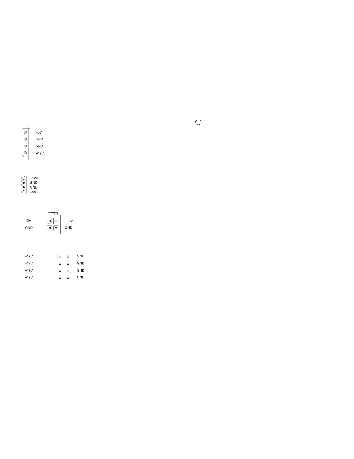
b) 5.25"-Stecker
c) 3.5"-Stecker
d) 4poliger ATX2.0-12V-Stecker
13
Table des matières
Page
1. Fournitures..........................................................................................................................................32
2. Consignes de sécurité.........................................................................................................................32
3. Description du fonctionnement............................................................................................................33
4. Eléments de commande et raccordements.........................................................................................33
5. Montage..............................................................................................................................................35
6. Manipulation........................................................................................................................................36
7. Maintenance & nettoyage...................................................................................................................38
8. Elimination...........................................................................................................................................38
9. Suppression des défauts.....................................................................................................................39
10. Caractéristiques techniques................................................................................................................40
11. Configuration des fiches......................................................................................................................41
12. Conseils & indications .........................................................................................................................42
1. Fournitures
Bloc dalimentation
Câble dalimentation
Mode demploi
2. Consignes de sécurité
La garantie ne couvre pas les dommages causés par un non-respect de ce mode demploi.
Nous déclinons toute responsabilité pour les dommages qui en résulteraient directement ou
indirectement
!
Nous nassumons aucune responsabilité pour les dommages matériels et corporels
causés par une manipulation inappropriée ou le non-respect des consignes de sécurité.
Dans de tels cas, tout droit à une garantie séteint!
Pour des raisons de sécurité et daccréditation (CE), toute transformation arbitraire et/ou modification du
produit est interdite.
Seule une exploitation dans des locaux secs et fermés est autorisée.
Seule une prise secteur réglementaire équipée dun conducteur de protection du réseau dalimentation public
ne peut être utilisée comme source de tension. Le sélecteur de tension du bloc dalimentation doit être réglé
sur la tension de secteur correcte (115V~ ou 230V~).
Un mauvais réglage entraîne la destruction du bloc dalimentation et des composants dordinateurs qui lui
sont raccordés, et un risque dexplosion et dincendie subsiste !! En cas de doute, demandez à lentreprise
compétente qui vous approvisionne en énergie !
Les appareils fonctionnant sur la tension de secteur doivent être tenus hors portée des enfants.
Soyez donc particulièrement prudent en présence denfants.
Dans les installations industrielles, les directives de prévention contre les accidents de lassociation
professionnelle pour les installations et le matériel dexploitation électriques doivent être respectées.
Dans les écoles, centres de formation, ateliers collectifs de loisirs ou de bricolage, lutilisation du
produit doit être surveillée par un personnel dencadrement qualifié.
32
Page 14

b) 5.25"-Stecker
c) 3.5"-Stecker
d) 4poliger ATX2.0-12V-Stecker
e) 8poliger ATX12V-Stecker
12. Tipps & Hinweise
Wie schon erwähnt, ist das Netzteil nach dem Ausschalten über den Power-Taster Ihres ATX-Gehäuses
im Standby-Modus.
Es ist also nicht von der Netzspannung getrennt! Ähnlich funktioniert z.B. auch ein Fernseher, den Sie
mit der Fernbedienung in den Standby-Modus versetzen können.
Das Netzteil "verbraucht" in diesem Standby-Modus immer noch Strom. Um Energie zu sparen, sollten
14 31
F
Introduction
Cher client,
Nous vous remercions davoir fait lacquisition de cette alimentation.
Ce produit a été contrôlé selon CEM et répond aux exigences des directives européennes et nationales
en vigueur. La conformité CE a été prouvée et les explications correspondantes sont déposées chez
le fabricant.
Pour ne pas compromettre cet état et pour assurer un fonctionnement optimal, il importe que lutilisateur se
conforme aux consignes de sécurité énoncées dans ce mode demploi.
Toutes raisons sociales et descriptions du produit sont des marques déposées du fabricant. Tous
droits réservés.
En cas de questions, adressez-vous à notre service de Conseil technique:
France: Tel. 0892 897 777, Fax 0 892 896 002
E-mail: technique@conrad.fr
Du lundi au vendredi: 8.00-18.00. Le samedi: 8.00-12.00
Autriche : Tel. 072 42/20 30 60, Fax 072 42/20 30 66
E-mail : support@conrad.at
Du lundi au jeudi, 8.00-17.00 heures, vendredi, 8.00-14.00 heures
Suisse : Tel. 0848/80 12 88, Fax 0848/80 12 89
E-mail : support@conrad.ch
Du lundi au vendredi. 8.00-12.00, 13.00-17.00 heures
Utilisation conforme aux dispositions
Le bloc dalimentation secteur ATX pour ordinateur est prévu pour être monté dans un boîtier dPC ATX
approprié.
Il sert à alimenter les composants du PC, comme la carte mère, le disque dur, CD-ROM, etc.
La carte mère doit disposer dun raccordement électrique ATX.
La puissance élevée de max. 350W (veuillez respecter les caractéristiques techniques) permet aussi
lalimentation de PC plus importants munis de nombreuses extensions.
Une utilisation contraire à la description préalable entraîne des dommages sur le produit ainsi que des risques
de court-circuit, dincendie, de choc électrique etc. Lensemble du produit ne doit pas être modifié ou transformé.
Le boîtier ne doit pas être ouvert. Les autocollants posés sur le produit ne doivent pas être abîmés ou retirés,
de même, aucune vis ou fixation ne doit être desserrée ou retirée.
Page 15

Sie das Netzteil über den Netzschalter ausschalten, wenn Sie Ihren Computer nicht benötigen.
Gleiches gilt selbstverständlich auch für alle anderen Geräte, die an dem Computer angeschlossen sind,
z.B. Monitor, Scanner, Lautsprecher usw.
Geräte ohne "echten" Netzschalter (z.B. viele PC-Lautsprecher, manche Monitore oder auch alle Geräte
mit Steckernetzteil) können über eine Steckdosenleiste mit Ein-/Ausschalter von der Netzspannung
getrennt werden.
Die Standby-Leistungsaufnahme eines kompletten PC-Systems kann leicht 50W erreichen.
Bereits nach einem Tag ist eine Kilowattstunde (1 kWh) sinnlos "verbraucht" und in Wärme
umgewandelt worden.
Die Anschaffung einer Steckdosenleiste mit Ein-/Ausschalter kann sich deshalb bereits nach einem Jahr
bezahlt machen.
Das gemeinsame Einschalten aller Verbraucher (PC, Monitor, Drucker usw.) führt
möglicherweise dazu, dass der Sicherungsautomat des zugehörigen Stromkreises auslöst, da
der Einschaltstrom zu hoch ist.
Falls dies bei Ihnen auftritt, schalten Sie zuerst den Schalter der Steckdosenleiste ein und
anschließend nacheinander die einzelnen Geräte.
Beim Ausschalten gehen Sie umgekehrt vor, zuerst Geräte ausschalten und danach die
Steckdosenleiste.
Es gibt auch sog. "Power-Manager", die das bequeme Ein-/Ausschalten einzelner Steckdosen
über Schalter an der Frontseite erlauben. Solche "Power-Manager" lassen sich z.B. unter dem
Monitor platzieren.
Tintenstrahldrucker müssen zuerst über den Ein-/Ausschalter des Druckers ausgeschaltet
werden, bevor die Netzspannung z.B. über die Steckdosenleiste abgeschaltet wird.
Andernfalls kann der Drucker den Druckkopf nicht in eine Parkposition bringen, die Düsen des
Druckkopfs könnten austrocknen!
Manche Drucker sollten immer an der Netzspannung angeschlossen bleiben, da sie sonst bei
Rückkehr der Netzspannung (also beim Einschalten über die Steckdosenleiste) einen
zusätzlichen Reinigungsvorgang durchführen. Die Kosten für diesen sinnlosen Tintenverbrauch
übersteigen oft die Stromeinsparung.
Beachten Sie unbedingt die Einschränkungen für den max. Stromverbrauch der einzelnen
Betriebsspannungen bei Punkt 10 dieser Bedienungsanleitung (siehe auch Aufdruck auf dem Netzteil)!
Durch Überlast wird das Netzteil zerstört! Weiterhin besteht dabei die Gefahr der Beschädigung
der angeschlossenen Verbraucher, z.B. Mainboard, Festplatten usw.
Falls Ihr Mainboard über den 4poligen ATX2.0-Anschluss für die +12V-Spannung verfügt, so verbinden
Sie ihn mit dem entsprechenden Anschluss des PC-ATX-Schaltnetzteils.
Der Anschluss dient für eine bessere Versorgung der Schaltregler auf dem Mainboard (die den
Strom/Spannung für die CPU erzeugen) und für eine Entlastung der +12V-Leitung des ATXStromsteckers.
1530
Page 16

16
The same also obviously applies for all other devices which are connected to the computer, e.g. monitor,
scanner, loudspeakers etc..
Devices without "real" power switches (e.g. many PC loudspeakers, some monitors and also all devices
with wall power supply) can be separated from the mains voltage with an on/off switch on a socket strip.
The standby power consumption of a complete PC system can easily reach 50W. After only a
single day, a kilowatt hour (1 kWh) has been uselessly "consumed" and converted into heat.
The purchasing of a socket strip with an on/off switch can therefore pay for itself after only one year.
Switching all connected devices (PC, monitor, printer etc.) on together can possibly lead to the
triggering of the automatic circuit breaker of the supplying circuit , because the starting current
is too high.
If this occurs, first switch on the switch of the socket strip and then the individual devices, one
after the other.
For switching-off, this sequence is reversed, with the devices being switched off first and then
the socket strip.
There are also so-called "power-managers" which permit the comfortable switching on/off of
individual sockets via switches on the front. Such "power managers" can be positioned e.g.
under the monitor.
Ink-jet printers must first be switched off via the on/off switch of the printer before e.g. the mains
voltage is switched off via the socket strip.
Otherwise, the printer cannot bring the print head into a parking position and the jets of the print
head could dry up!
Some printers should always remain connected to the mains voltage, because they otherwise
carry out an additional cleaning procedure upon the return of the mains voltage (i.e. upon
switching-on via the socket strip). The cost of this pointless use of ink often exceeds the saving
on electricity.
Always note the restrictions for the max. current consumption of the individual operating voltages at
Point 10 of these operating instructions (see also imprint on the power supply unit)!
The power supply unit is destroyed by overloading! In this there is also a risk of damage to the
connected devices, e.g. mainboard, hard drives etc..
If your mainboard has the 4-pole ATX2.0 connection for the +12V voltage, then connect it with the
corresponding connection of PC-ATX switching power supply.
The connection is for better supplying of the switching controllers on the mainboard (which produce the
current/voltage for the CPU) and to reduce the load on the +12V line of the ATX plug.
The same applies for the 8-pole plug.
29
Page 17

GB
Introduction
Dear Customer,
we thank you for purchasing this power supply unit.
The product is EMC-tested and fulfils the requirements of the applicable European and national
guidelines. The CE-conformity has been proven, the corresponding declarations have been deposited
with the manufacturer.
In order to maintain this state and to ensure safe operation, you as a user must follow these operating
instructions!
All the company names and product designations included here are trademarks of the respective
bearers. All rights reserved.
If you have any questions, please contact our technical advice service:
Germany: Tel. 0180/5 31 21 16 or 0 96 04/40 88 47, Fax 0 96 04/40 88 48
E-mMail: tkb@conrad.de
Mon. to Fri. 8.00-18.00
Austria: Tel. 072 42/20 30 60, Fax 072 42/20 30 66
E-mMail: support@conrad.at
Mon. to Thur., 8.00-17.00, Fri. 8.00-14.00
Switzerland: Tel. 0848/80 12 88, Fax 0848/80 12 89
E-mMail: support@conrad.ch
Mon. to Fri. 8.00-12.00, 13.00-17.00
Correct Use
The PC-ATX switching power supply is intended for integration in a corresponding PC-ATX housing.
It is for supplying electricity to PC components such as mainboard, hard-drive, CD-ROM etc.
The mainboard must have an ATX power connection.
Due to the high power of max. 550W (please note the technical data!) even large PCs with numerous
expansions can be supplied with electricity.
Any use other than that which is described above leads to the damaging of this product and also involves
the risk of e.g. short circuit, fire, electrical shock etc.. The product must remain entirely unaltered and
unconverted. The housing must not be opened. The stickers on the product must not be damaged or removed,
neither may any bolts or fastenings of the product be loosened or removed.
1728
(black)
(red)
(yellow)
(black)
(black)
(red)
(yellow)
(black)
(black)
(yellow)
(black)
(yellow)
(black)
(yellow/black)
(black)
(black)
(black)
(yellow/black)
(yellow/black)
(yellow/black)
b) 5.25" plug
c) 3.5" plug
d) 4-pole ATX2.0-12V plug
e) 8-pole ATX12V plug
12. Tips & Advice
As already mentioned, the power supply unit is in standby mode after switching-off via the power button
of your ATX housing.
It is therefore not separated from the mains voltage! A television which can be put on standby mode by
remote control is an example of a device which functions in a similar way.
The power supply unit still "consumes" electricity in standby mode. In order to save electricity you should
switch the power supply unit off using the power switch when you do not need your computer.
Page 18

Table of Contents
Page
1. Scope of Delivery ...............................................................................................................................18
2. Safety Instructions..............................................................................................................................18
3. Description of Function.......................................................................................................................19
4. Operating Elements and Connections................................................................................................19
5. Installation ..........................................................................................................................................20
6. Operation............................................................................................................................................22
7. Maintenance & Cleaning....................................................................................................................24
8. Disposal..............................................................................................................................................25
9. Trouble Shooting................................................................................................................................25
10. Technical Data....................................................................................................................................26
11. Terminal Conditions of the Plug .........................................................................................................27
12. Tips & Advice......................................................................................................................................28
1. Scope of Delivery
Power Supply Unit
Power Cord
ATX Adapter Cable (24pol. to 20pol.)
Operating Instructions
2. Safety Instructions
The warranty claim expires in the event of damage which is caused by non-adherence to
these operating instructions. We accept no liability for consequential damage!
We accept no liability for damage to property or personal injury which is caused by
incorrect handling or non-adherence to the safety instructions. In such cases, every
warranty claim expires!
For reasons of safety and qualification (CE), the independent conversion and/or alteration of the
product is not permitted.
Operation is only permitted in dry indoor spaces.
Only a proper mains plug with protective conductor of the public supply network may be used as a voltage
supply. The power supply unit has a full-range input (100-240V~, 50-60Hz).
Devices which are operated on mains voltage should not be allowed to get into the hands of children.
Therefore, exercise particular caution in the presence of children.
In commercial establishments, the accident-prevention regulations of the association of the commercial trade
association for electrical devices and appliances are to be observed.
In schools, training establishments, hobby and self-help workshops, the operation of the product is to be
responsibly supervised by trained personnel.
18
11. Terminal Conditions of the Plug
a) ATX Plug
The colours of individual lines (e.g. PS ON and Power OK) may possibly differ.
20-pole version:
24-pole version:
27
(red)
(red)
(white)
(black)
(black)
(black)
(green)
(black)
(blue)
(orange)
(yellow)
(purple)
(gray)
(black)
(red)
(black)
(red)
(black)
(orange)
(orange)
(red)
(red)
(white)
(black)
(black)
(black)
(green)
(black)
(blue)
(orange/
brown)
(yellow)
(purple)
(gray)
(black)
(red)
(red)
(orange)
(orange)
(red)
(black)
(black)
(black)
(yellow)
(orange)
Page 19

3. Description of Function
The power supply unit is supplied with mains voltage/electricity via the mains voltage socket. The power
supply unit has a full range input (100-240V~, 50-60Hz).
The PC-ATX switching power supply converts this mains voltage into the DC voltages required internally by
the computer (+5V, +12V, -5V, -12V and +3.3V).
A built-in fan draws off excessive heat arising from this conversion.
The product can be switched on and off via the power switch.
The computer does not start up upon the switching-on at the power switch. At first, the power
supply unit and also the connected mainboard are in the so-called "standby" mode. To start the
computer, the power button on the front of your ATX housing must be pressed briefly. The button
must be connected via a cable with the corresponding connection to your mainboard (e.g. "ATX
Power" connection or similar, see instructions for your mainboard).
If you switch your computer off using the power button, there is always still a standby voltage
on your mainboard.
This is required e.g. to switch the PC on via the keyboard or mouse (insofar as the BIOS of your
PC provides this option) or the automatic switching on/booting up of modem/ISDN call/network
access (independent of BIOS and software).
In the event of interventions in your computer (e.g. if you want to install a new plug-in card), the
ATX power supply unit must therefore be switched off beforehand via the power switch on the
ATX power supply unit and be separated from the mains voltage. Always also pull out the mains
plug!
4. Operating Elements and Connections
19
Please note:
With newer versions of
the power supply unit,
the arrangement of the
operating elements and
connections can possibly
change.
10. Technical Data
Operation with the mains voltage, 100-240V~, 50-60Hz, full range
Output voltages and output currents (see also print on the power supply unit):
+3.3V= max. 27A
+5V= max. 29A
+12V= CPU max. 18A
+12V= I/O max. 18A
-5V= max. 0.3A
-12V= max. 0.8A
+5V= (standby) max. 2A
Always adhere to the above restrictions with the individual operating voltages. It is not
possible to make use of all the maximum current values together!
The capacities in the +3.3V- and +5V range must not exceed 150W in total, the capacities
in the +3.3V/+5V/+12V (CPU and I/O) must not exceed 528W .
Voltage connections (number of 5.25"- and 3.5"- current plugs may possibly be different in newer versions
of the power supply unit):
- 9 * 5.25"
- 1 * 3.5"
- 1 * 24-pole ATX (for server mainboard; for "normal" mainboards the supplied adapter is necessary)
- 1 * 4-pole ATX2.0-12V plug (only for mainboard with matching connection)
- 1 * 8-pole ATX12V plug (only for mainboard with matching connection)
Power switch on rear of device
Fan built-in
Active PFC (Power Factor Correction)
26
}
max. 150W!!
}
max. 528W!!
Page 20

AFan
The fan blows the heated air out of the power supply unit.
Therefore never cover the ventilation openings of the power supply unit. If you were to do this,
the accumulation of heat would destroy the power supply unit and the connected components!
B Power Switch
The power supply unit is switched on and off by the power switch.
Please also make sure that you note point 3 of these operating instructions!
C Mains Socket
Switch the power supply unit off (position "O" of the power switch). Then connect the connection to a
proper mains plug socket with protective earthing conductor via the power cord provided.
D Bolt Holes
The four bolt holes on the outside corners of the power supply unit are for fastening the power supply
unit to the PC housing.
Where possible, use all four fastening holes for fastening, because the high weight of the power
supply unit means that there is a risk that e.g. the PC housing might be damaged during
transportation and that the power supply unit might become loose.
5. Installation
If you have no technical knowledge of the installation, have the installation carried out
by a SKILLED PERSON or at an appropriate technical workshop!
Incorrect installation will damage the power supply unit as well as your computer and all
the devices connected to it. In addition, it is connected with risks such as e.g. short circuit,
electrical shock and the risk of fire.
Caution, danger to life!
Switch off both the computer into which it is intended to install the power supply unit and
all connected devices and separate all devices from the mains voltage. Pull the mains
plug out! Switching off at the power switch is not enough!
Open the housing of your computer and carefully remove the housing lid.
If the power supply unit is intended to serve as a replacement for e.g. an old, defective power supply
unit, then you must first remove the present power supply unit. First, carefully loosen all connecting plugs
for the mainboard and the installed devices. Hold the old power supply unit tight and remove all lock
bolts from the power supply unit, so that it can be taken out of the PC housing.
20
8. Disposal
Dispose of the useless product in accordance with the applicable legal regulations.
9. Trouble Shooting
With the "PC-ATX 550W switching power supply" you have purchased a reliable product which has been
built to the latest standards of technology.
Despite this, problems and malfunctions can still arise.
We would therefore like to describe to you how possible faults may be rectified.
Always follow the safety instructions!
Problem Possible Solution
No function Is the device switched on?
Has the power cord been correctly connected at both ends?
Is the mains socket functional?
Are all the connections on the devices in the inside of the computer correct? If
e.g. the hard drive cable is stuck in twisted, the computer might not start due
to a short circuit, and the power supply unit not start!
If you have assembled a new PC; some mainboards do not start if the CPU fan
is turning too slowly (e.g. CPU fans with lower revolutions for reduction of noise).
Computer does not Upon the switching-on of the power supply unit (via the power switch on the
start up when rear side
the power supply of the ATX power supply units), only the standby voltage is on the mainboard.
unit is switched on Only a brief press of the power button on the front of your PC housing
switches the ATX power supply unit on (insosofar as the power button is
connected with
the corresponding connection of your mainboard).
Therefore check that the power-button is correctly connected with
the mainboard.
25
Page 21

Bolt the new power supply unit firmly onto your PC housing with 4 bolts (inch-measure thread, length
of thread max. approx. 5mm).
The power supply unit has a wider ATX plug than that of conventional power supply units. This is for
connection to appropriate mainboards (e.g. servers).
For connection to a conventional mainboard with 20-pole ATX connection, the adapter
cable provided (24-pole to 20-pole) is always to be used.
The 24-pole ATX plug must not be directly inserted into the 20-pole connection of the
mainboard! This would destroy the power supply unit, the mainboard and also all other
connected PC components!
Connect the 24-pole ATX plug of the power supply unit with the 24-pole socket of the adapter cable,
then plug the 20-pole plug of the adapter cable into the 20-pole socket of the mainboard.
Warning!
If forced the ATX plug can also be plugged the wrong way round onto the connection on the
mainboard! It must be possible to plug the ATX plug in lightly and to then click it cleanly into
place with the clip on the side.
The PC-ATX power supply unit also has a 4-pole ATX2.0-12V plug which is necessary for many Intel-
P4 mainboards.
The matching connection on the mainboard is for connecting the +12V voltage to the mainboard via
extra lines, which is intended to relieve the load on the +12V line of the ATX current plug.
If your mainboard has this connection, always make sure that you connect it with this plug.
The 8-pole plug (2 rows with 4 contacts) can only be connected to corresponding mainboards (e.g.
servers). With conventional mainboards, the connection has no function.
Connect all of your devices with the suitable current plugs, e.g. hard drive, DVDROM etc.
Lay all the cables into your PC cleanly and straight, making sure that the cable is not crushed or otherwise
damaged. Protect the cable from the sharp edges in your PC housing. Make sure that they do not get
into the fan of the PC.
Use binders to fix the cables.
Check: is the power button on the front of your ATX housing connected with the corresponding
connection on the mainboard?
Switching on at the power switch does
not normally lead to the switching-on of the PC (can
possibly be activated/set in the BIOS of the main board)!
Close the housing of your computer and connect it up once more to your other devices and accessories.
Connect your computer to the mains voltage and switch the ATX power supply unit on.
The computer does not normally start yet. Press briefly upon the power button on the front of your ATX
housing in order to switch the PC on.
21
7. Servicing and Cleaning
Regularly check the technical safety of the power supply unit, e.g. damage to the power cord or to the housing.
If it is to be assumed that safe operation is no longer possible, then the power supply unit is to
be put out of service and made secure against unintended use. Pull the mains plug from the
socket!
It is to be assumed that safe operation is no longer possible if
- if the device shows visible damage,
- if the device no longer functions or
- after a long period of storage under unfavourable conditions or
- after heavy demands from transportation.
Before cleaning or servicing the device, always follow the following safety instructions:
There are no parts within the device which are to be maintained by the user.
Live parts can be exposed when opening covers or removing parts.
Before cleaning, servicing or repair the device must be separated from all voltage sources; pull
the mains plug out! Switching off at the power switch isnt enough!
Capacitors in the device can still be live, even if the device has been separated from all voltage
sources.
Repairs may only be carried out by skilled personnel who are familiar with the risks involved and
the relevant regulations.
The built-in instrument fuse is only to be replaced using a special tool. Therefore, do not try to
replace the fuse yourself; leave this to a technical workshop.
A dry, clean, fibre-free cloth suffices for cleaning the exterior of the housing.
The dust which has gathered on the power supply unit and the fan blades can be removed using a vacuum
cleaner.
24
Page 22

If your computer does not start correctly, then switch it off immediately and check all the settings and
cable connections.
Before you open the housing to check it, remember to switch off all devices, to separate
them from the mains voltage and to pull the plug out (see above)!
6. Operation
Never switch the power supply unit (or the computer into which the power supply unit has been integrated)
on straight away if it is brought from a cold room into a warm room. The condensation water arising from
this can under unfavourable circumstances destroy the power supply unit and/or the computer.
First allow the power supply unit (and the computer into which the power supply unit has
been integrated) to reach room temperature before you connect it to the mains voltage
and switch it on. This can under certain circumstances take several hours.
Make sure that there is sufficient ventilation of the power supply units in the operating phase. Do not place
the computer next to radiators. Do not put the rear of the computer too close to walls or furniture. Never cover
the ventilation openings on the power supply unit inside or outside!
The computer with the power supply unit integrated into it must be set up in such a way that air can circulate.
Do not put any objects, e.g. paper clips, pens, needles and knitting needles etc. into the
ventilation slits and device openings. This prevents the operation of the fan and there
also exists a risk of death in the event of contact with electrical lines and connection
points!
When setting up your computer, make sure that the mains cable does not become kinked or crushed.
Always immediately replace a damaged power cord with a new power cord with the same specifications.
Operation is only permitted in dry indoor spaces. Contact with moisture is always to be
avoided! There is the risk of a possibly fatal electrical shock!
Avoid the following adverse environmental conditions where the device is set up and in during transportation:
- wetness or excessive humidity
- extreme cold or heat
- dust or combustible gases, vapours or solvents
- strong vibrations
- strong magnetic fields, such as close to machines or loudspeakers
Before each use, check the product for damage!
22
In the event that you ascertain damage, the product must NOT be connected to the mains
voltage! There is danger to life!
Switch the power supply unit off via the built-in power switch if the computer into which it is integrated is not
going to be used for a long period of time.
In standby mode, the power supply unit has a power consumption of up to several Watts. While
it is true that this does not sound like much, several kilowatt hours per month can nonetheless
mount up and be uselessly consumed over longer standby periods.
Do not pull the mains plug out of the socket by the cable! Always pull the plug out of the socket by using the
gripping surfaces on the sides of the plug.
Do not touch the power supply unit or power cord/plug with damp or wet hands! There
is the danger of a potentially fatal electric shock!
23
 Loading...