

Page 1
CONRAD IM INTERNET http://www.conrad.de
Imprint
These operating instructions are published by Conrad Electronic GmbH, KlausConrad-Str. 1,92240 Hirschau/Germany
No reproduction (including translation) is permitted in whole or part e.g.photocopy, microfilming or storage in electronic data processing equipment, without
the express written consent of the publisher.
The operating instructions reflect the current technical specifications at time of
print.We reserve the right to change the technical or physical specifications.
©
Copyright 1998 by Conrad Electronic GmbH.Printed in Germany.
Note de l´éditeur
Cette notice est une publication de la société Conrad Electronic GmbH,Klaus-Conrad-Str. 1,92240 Hirschau/Allemagne.
Tous droits réservés, y compris traduction. Toute reproduction, quel que soit le
type,par exemple photocopies,microfilms ou saisie dans des traitements de texte
electronique est soumise à une autorisation préalable écrite de l`éditeur.
Impression,même partielle,interdite.
Cette notice est conforme à la règlementation en vigueur lors de l´impression.
Données techniques et conditionnement soumis à modifications sans aucun préalable.
©
Copyright 1998 par Conrad Electronic GmbH.Imprimé en Allemagne.
Impressum
Diese Bedienungsanleitung ist eine Publikation der Conrad Electronic GmbH.
Alle Rechte einschließlich Übersetzung vorbehalten.Reproduktionen jeder Art,z.B.
Fotokopie, Mikroverfilmung, oder die Erfassung in elektronischen Datenverarbeitungsanlagen,bedürfen der schriftlichen Genehmigung des Herausgebers.
Nachdruck,auch auszugsweise,verboten.
Diese Bedienungsanleitung entspricht dem technischen Stand bei Drucklegung.
Änderung in Technik und Ausstattung vorbehalten.
©
Copyright 1998 by Conrad Electronic GmbH.Printed in Germany.
Impressum
Deze gebruiksaanwijzing is een publikatie van Conrad Electronic Ned BV.
Alle rechten, inclusief de vertaling, voorbehouden. Reprodukties van welke aard
dan ook,fotokopie,microfilm of opgeslagen in een geautomatiseerd gegevensbestand,alleen met schriftelijke toestemming van de uitgever.
Nadruk,ook in uittreksel, verboden.
Deze gebruiksaanwijzing voldoet aan de technische eisen bij het ter perse gaan.
Wijzigingen in techniek en uitrusting voorbehouden.
©
Copyright 1998 by Conrad Electronic Ned BV. Printed in Germany.
*308-11-98/05-MS
NL
D
F
GB
100% recycling paper.
Bleached
without
chlorine.
100% Recycling-papier.
Chloorvrij
gebleekt.
100% Recycling-Papier.
Chlorfrei
gebleicht.
100%
papier
recyclé.
Blanchi
sans chlore.
OPERATING INSTRUCTIONS
Digital Multimeter
VC630, VC650, VC670 TRUE RMS
Item-No.:122645, 122653, 122661
NOTICE D´EMPLOI
Multimétres numériques
VC630, VC650, VC670 TRUE RMS
Node commande:122645, 122653, 122661
BEDIENUNGSANLEITUNG
LCD Digitalmultimeter
VC630, VC650, VC670 TRUE RMS
Best.-Nr.:122645, 122653, 122661
GEBRUIKSAANWIJZING
Digitale multimeter
VC630, VC650, VC670 TRUE RMS
Bestnr.:122645, 122653, 122661
NL
D
F
GB
Page 2 - 44
Page 45 - 90
Seite 91 - 134
Pagina 135 - 175
Page 2

3
• VC 630 and VC 650: measurement of capacitors up to 40 uF max.; VC
670 up to 400 uF
• Frequency measurements up to 4 MHz max.
• VC 630 and VC 650: resistance measurements up to 40 MOhm max.; VC
670 up to 400 MOhm max.
• Continuity test, diode test, transistor test (hfe parameter)
• VC 650 and VC 670: temperature measurements using the temperature
adapter available as an option
• VC 650 and VC 670: logic level measurements
• VC 650 and VC 670: signal generator output (TTL) from 1 Hz up to
5 kHz (in steps)
• A measurement must not be performed under unfavourable ambient
conditions. Unfavourable ambient conditions include:
- wetness or excessive air humidity,
- dust and combustible gases, fumes or solvents,
- thunderstorms or storm conditions such as strong electrostatic fields,
etc.
Any use other than as described above can lead to damage to the product and can also cause hazards such as for example, short-circuit, fire,
electric shock, etc. No part of the product must be modified or converted! The safety information must be observed!
2. Introduction, presentation
The three digital multimeters VC 630, VC 650 and VC 670 are menu-driven instruments each with a multifunction display. The otherwise customary rotary switch for selecting measurement functions is entirely missing. Therefore, logically , there are also no contact-closure or other common switch problems. With the base model VC 630, in addition to the
normal multimeter functions, transistor tests, frequency and capacity
measurement are possible. With the VC 650, in addition temperature
2
Digital Multimeter VC 630, VC 650, VC 670 TRUE RMS
Attention! You must read this!
Please read these operating instructions thoroughly. Damage arising
from failure to observe the operating instructions will void any guarantee claims. Failure to observe the instructions may also endanger life!
We accept no liability for consequential damage resulting from this. It is
assumed that the user has basic knowledge of handling measuring
instruments and PCs. Keep these operating instructions in a safe place.
Contents
Page
1. Intended use........................................................................................... 2
2. Introduction............................................................................................ 3
3. Safety instructions.................................................................................. 4
4. Functional description of
operating elements (buttons operation).............................................. 7
5. Description of measurement functions............................................... 13
6. Maintenance, battery replacement, fuse replacement,
setting up the measuring instruments................................................ 38
7. Technical data and measurement tolerances..................................... 41
1. The intended use of the measuring
instrument comprises:
• DC voltage measurements up to 1000 VDC max.
• AC voltage measurements up to 700 VAC rms max.
• DC or AC current measurements up to 20 A max.
• VC 670: TRUE RMS - AC current measurements up to 20 A max. and AC
voltage measurements up to 700 VAC rms max.
GB
Page 3

5
• The measuring instrument may not be used in overvoltage category III
installations per IEC 664. The measuring instrument and test leads are
not protected against arc explosions (IEC 1010-2-031, Section 13.101).
• Measuring instruments and accessories do not belong in the hands of
children!
• In commercial facilities the accident-prevention regulations of the
Industrial Employers' Liability Association for electrical systems and
equipment must be observed.
• In schools, training facilities, hobby and self-help workshops, the handling of measuring instruments must be supervised responsibly by trained personnel.
• Except where this can be performed manually, live parts may be exposed when opening covers or removing components. The points of measurement may also be live. Before any adjustment, maintenance, repair
or replacement of components or assemblies necessitating opening the
unit, the unit must be disconnected from all voltage sources and circuits. If adjustment, maintenance or repair of the opened unit under
voltage is unavoidable, this may only be carried out by a specialist
familiar with the associated risks and applicable regulations (VDE0100, VDE-0683, VDE-0701).
• Capacitors in the unit may remain charged even when the unit has
been isolated from all voltage sources and circuits.
• Take particular care when dealing with voltages greater than 25 V AC
or greater than 35 V DC. Even at these voltages it is possible to receive
a lethal electric shock if electrical conductors are touched.
Therefore, first of all switch off the voltage source, connect the measuring instrument to the test points of the circuit to be measured, set the
required voltage measuring range on the measuring instrument and
only then switch on the voltage source. After the measurement has
been completed, switch off the voltage source and remove the test
leads from the circuit test points.
• Before every voltage measurement, ensure that no other measurement function is active (resistance measurement, diode test, etc.).
4
measurement (using the adapter available as an option) and logic tests
are possible. Furthermore, a TTL signal generator is built in. The output
frequency is between 1 Hz and 5 kHz.
Finally, the VC 670 is configured as a true rms multimeter. True rms
means that independently of the measured AC current and voltage
waveform, the multimeter always displays the true rms value of the measurement. In addition, the following features are present in the VC 650:
capacity measurement up to 400 uF max., true rms AC voltage measurement up to 700 V , true rms AC current measurement up to 20 A max. and
resistance measurement up to 400 MOhm max. Furthermore, the VC 670
DMM has switchable back-lighting and an acoustic measured value indicator (TONE) ; according to the level of the measurement, a higher or
lower signal tone sounds.
All three DMMs have a serial interface, via which communication with a
PC becomes possible. The software (diskette) and the additional hardware (interface lead) are available as an option. If the measuring instrument is not in use for longer than approx. 30 min., the AUTO POWER OFF
function then switches the instrument off. The multimeters can be used
universally, in hobby, educational and (non-industrial) commercial applications, etc.
3.Safety instructions
• The VC 630, VC 650 and VC 670 TRUE RMS digital multimeters are EMC
and safety-approved (CE for domestic and commercial use, not for
industrial use) and meet the 89/336/EU EMC directive and 73/23/EU low
voltage directive.
• These units have been constructed in accordance with VDE 0411 Part 1
= EN or IEC 61010-1 protective measures for electronic measuring
instruments and left the factory in a perfect technically-safe condition.
To maintain this condition and to ensure safe operation, it is essential
for the user to observe the safety instructions and warning notes which
are contained in this user manual.
• Current measurements are only approved in circuits which are themselves protected by a 20 A 250 V fuse and in which no voltages above 250
VAC or 250 VDC are present.
Page 4
7
• Never switch the measuring device on immediately after it has been
brought from a cold into a warm area. The resulting condensation
water could damage the unit. Allow the unit to come to room temperature before switching it on.
4. Functional description of operating
elements (buttons operation)
4.1 Basic description
Illustration of front view: see fold-out page
4.2 Basic display
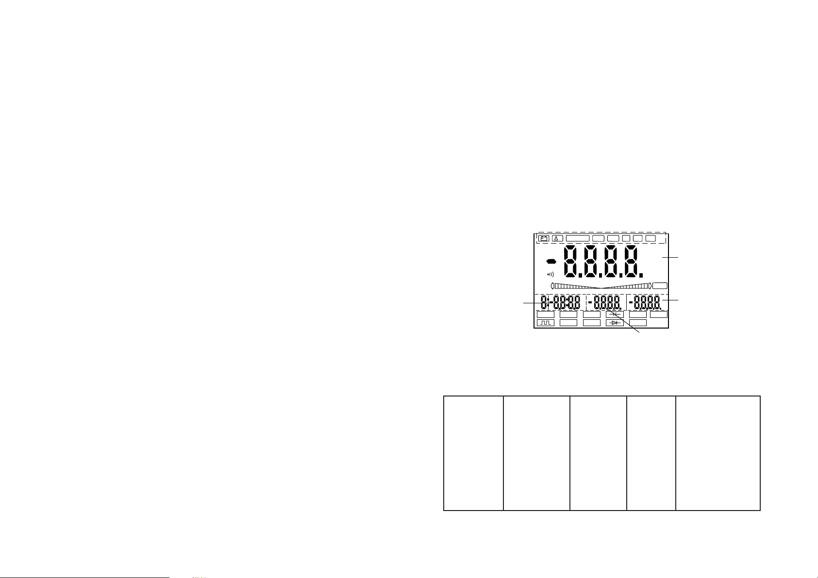
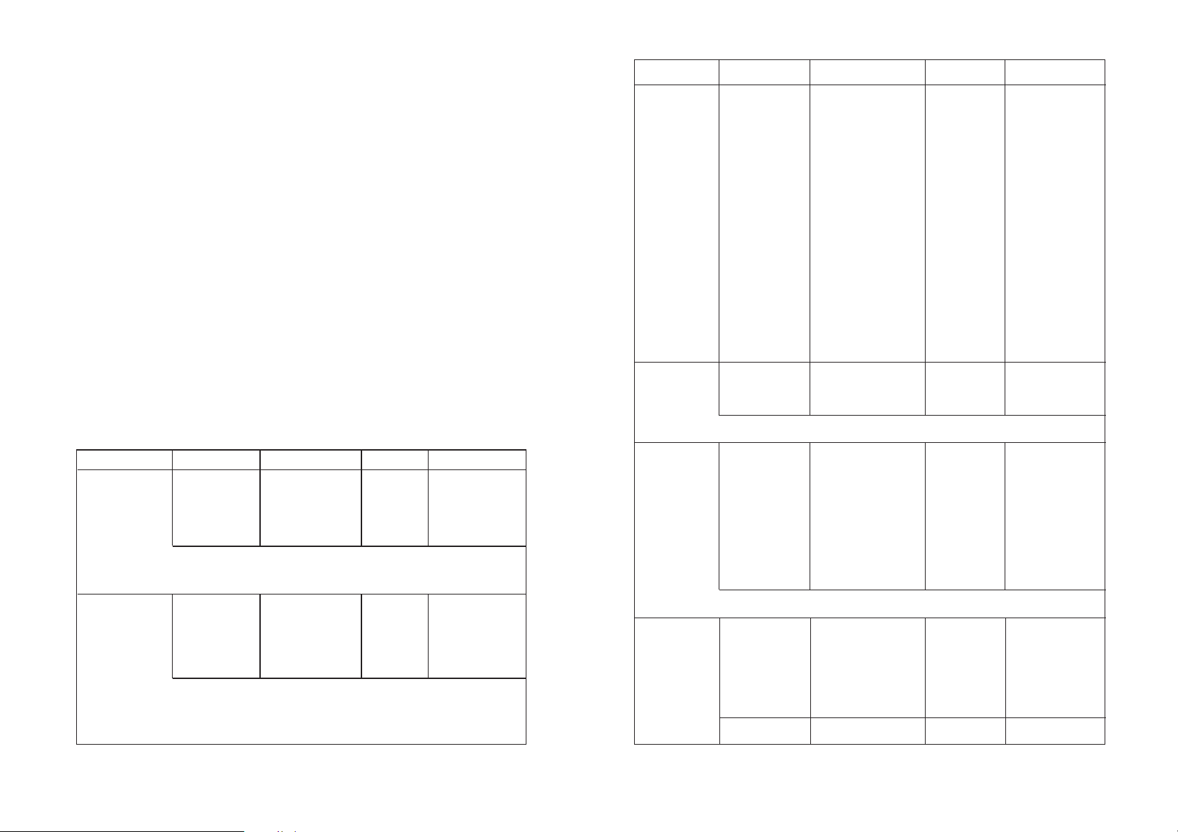
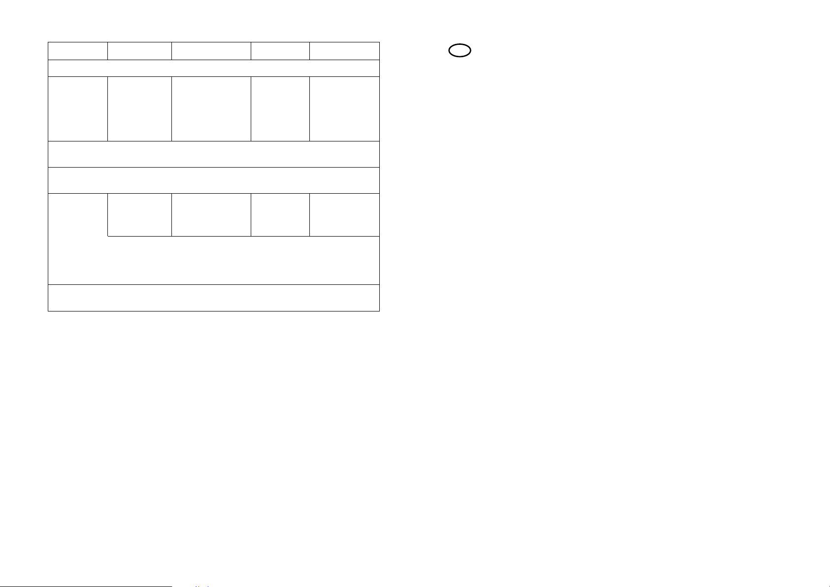
According to the DMM model and measurement functions, various indications can be seen in the main display (S0) and in the sub-display S1, S2
and S3. The following table explains these
Meas. func S0 S1 S2 S3
ACV AC volts Hz (<100kHz) ——- ——ACA AC amps Hz (<100kHz) ——- ——DCV DC amps ——- ——- ——-
+
TRIG
±
REC
½
cly
ms
mV
%
dB
mV
KHz
¡C¡F
MAX MIN
%
MIN/MAX
TIME LMT PH REC RCLL
mVA%
AUTO
AC DC
TONE
Mk½Hz
¡C¡FnumF
HOLD
0-10-20-30 -30-20-10
Hz hfe
Logic
VOLT
½
mAATEMP
S0
S1
S2
S3
6
• Before every change in measuring range, the test leads or adapters
must be removed from the test points. Before every measurement,
check the measuring instrument and test leads and adapters for
damage.
• The measuring instrument should not be used in areas or under adverse environmental conditions, in which inflammable gas, fumes or dust
are present or can occur. For your own safety it is essential to avoid the
measuring instrument or test leads becoming damp or wet. Avoid operation in the immediate vicinity of
a) strong magnetic fields (loudspeakers, magnets)
b) electromagnetic fields (transformers, motors, coils, relays, contac-
tors, electromagnets, etc..)
c) electrostatic fields (charges/discharges)
d) transmission aerials or HF generators
The measuring instrument can otherwise be damaged.
• For your own safety it is essential to avoid the measuring instrument or
test leads and adapters becoming damp or wet.
• When measuring, use only the test leads and optional matching adapters supplied with the measuring instrument. No others may be used.
• To avoid electric shock, care should be taken that the test probes and
the connections (measurement points) are not touched during measurement, not even indirectly.
• The voltage between any socket of the measuring instrument and
earth must not exceed 500 VDC or VAC rms.
• If it can be assumed that safe operation is no longer possible, then the
unit must be switched off and protected against unintentional operation.
It can be assumed that safe operation is no longer possible, if
- the unit shows visible signs of damage,
- the unit no longer functions and
- after prolonged storage under unfavourable conditions or
- after severe transportation stress.
Page 5
9
„MIN/MAX“ detection of the highest and lowest measured values
„TIME“ internal clock; the indication is in minutes and seconds up
to one hour and beyond this in hours and minutes. Maximum indication 23:59 (23 hours, 59 minutes)
„LMT“ "LIMIT" = comparative measurement with selectable upper
and lower limits (VC 670 only)
„PH“ "Peak Hold" = peak value measurement indication (VC 650
and VC 670 only)
„REC“ "Record" = record/store a measured value; there are 10
memory locations available. The number of the current
memory location is shown on the extreme left of the display.
„RCLL“ "Recall" of a stored measured value. For memory location
details see "REC" above
remaining positions
„HOLD“ "Data Hold" = the measured value is held (e.g. pending
transcription) until the "HOLD" button is pressed again or
the DMM switched off..
„AUTO“ is displayed when automatic range control is active.
„TONE“ tone signal for measured value recognition (VC 670 only)
„TRIG±“ trigger button for frequency measurement. Triggering on
the positive "+" or negative "-" edge of the signal to be
measured.
„Logic“ logic function display (VC 650 and VC 670 only).
„HI“ high logic level measurement
„LO“ low logic level measurement
8
4.3 Display information and operating mode symbols
Upper header, after the "ENTER MENU" button is pressed
„Æ%“ stands for "REL" = relative value measurement; possible
with ACV, DCV, Ohm, continuity, diode test, capacity, mA,
uA and A. The difference relative to a certain measured
value is displayed. The function is switched off by pressing
the "ENTER" button.
Resistance Ohm ——- ——- ——Continuity ——- ——- ——Diode test mV ——- ——- ——hfe hfe ——- ——- ——Capacitor test nF, uF ——- ——- ——Hz Hz, kHz, MHz V (olt) ——- ms, 1/2 Period
(0,01 - 99 msec)
TEMP °C / °F °F / °C ——- ———
TTL-gen. Hz ——- ——- ——LOGIC Hi, Lo Hz V TTL/3V-CMOS/
5V-CMOS
D% Variation Ref. value Diff. % ——-
MIN/MAX inst. Measurement ——-
value
MIN MAX
PH = Peak inst. measurem. ——- Max. value ——Hold value („frozen“)
TIME (clock) - - - hours, minutes,
seconds <24h
Page 6

11
V = volt (unit of electrical potential difference)
A = ampere (unit of electrical current)
Hz = hertz
kHz = kilohertz (exp.3)
k½ = kilohm (exp.3)
M½ = megohm (exp.6)
pF = picofarad (pico = exp. -12)
nF = nanofarad (nano = exp.-9)
uF = microfarad (micro = exp.-6)
4.4 Configuration of buttons and functional description with
button operation
4.4.1 General
All parameters can be changed/set by means of the various buttons on
the instrument. According to the instrument model, the following settings are possible:
"TRIG" (all three DMMs), „ „ lighting (VC 670 only), „ „ tone signal
(VC 670 only), "RANGE" (manual range setting), "AC/DC" with „½ “,
"HOLD", "POWER" (on/off), "ENTER MENU" (confirmation button), „“
(measurement function button via "ENTER"), "mA TEMP A" (measurement function button to the right of "ENTER"); "TEMP" (VC 650 and VC
670 only), "< >" (selection-aid button), „HzhfeLogic „ (measurement function button to the left of ENTER); „ „ and "Logic" (VC 650
and VC 670 only)
4.4.2 TRIG
a) TRIG button
This button is required for frequency measurement to switch from
positive triggering to negative triggering. Positive triggering "+"
means that the signal to be measured is captured on its rising
10
„- - - -“ logic level measurement between high and low
„PASS“ indication for LMT function (VC 670 only), meaning that the
measured value is somewhere between the previously-set
lower and upper limits
„hfe“ hfe (amplification) parameter indication during transistor
test measurements
„O.L“ "Overload" = measured value too great, ie. measurement
range limit exceeded
„ „ signal generator TTL output symbol (VC 650 and VC 670
only)
„ „ symbol for battery replacement
„°C“ degrees Celsius unit of measurement during temperature
measurements with optional temperature adapter (VC 650
and VC 670 only)
„°F“ degrees Fahrenheit unit of measurement during tempera-
ture measurements with optional temperature adapter (VC
650 and VC 670 only)
„->I-“ symbol for diode test
„-I(-“ symbol for capacity measurements of bipolar and unipolar
capacitors
„ “ symbol for acoustic continuity test
all remaining symbols stand for the various units of measurement:
AC = alternate unit
DC = direct unit
mV = millivolt (exp.-3)
+
–
Page 7

13
ly-measured value is held, or 'frozen'. The "HOLD" symbol appears at the
right-hand edge of the screen. In this condition, other than the "HOLD"
button, only the "ENTER" measurement function button and "POWER"
switch have an effect on the settings. The remaining buttons lose their
functions (being switched off).
To release the current measurement again, press the "HOLD" button
once more. The (new) instantaneously-measured value is displayed.
4.4.6 POWER
The measuring instrument is switched on or off by means of the
"POWER" switch. If the measured value does not change within about
30 minutes, the measuring instrument switches itself into "stand by"
mode. Energy consumption is reduced by this auto-power-off feature.
5.Setting the measurement function with the
buttons surrounding "ENTER"
Arranged around the "ENTER" button, the following functions are selectable:
a) above "ENTER"
- "V"; AC voltage measurement up to 700 VAC rms max. (true rms for
VC 670),
- "V"; DC voltage measurement up to 1000 VDC max.,
- resistance measurement up to 40 MOhm max. (VC 670 up to 400
MOhm) and continuity test (acoustic) up to 20 Ohm max.
- "-|(-"; capacity measurement up to 40 uF max. (VC 670 up to 400 uF)
and "->|-"; diode test.
b) to the right of "ENTER"
- "mA"; DC and AC current measurements up to 400 mA max. (true
rms for VC 670)
- "A"; DC and AC current measurements up to 20 A max. (true rms
for VC 670)
- temperature measurements with optional adapter (VC 650 and VC
670 only)
12
edge. Negative triggering "-"means that the signal to be measured is captured on its falling edge.
b) Lighting (VC 670 only)
Press the button for about 2 seconds. The back-lighting is switched on for improved readability under adverse light conditions.
Press the button again for about 2 seconds. The back-lighting is
switched off.
Attention!
Do not leave the lighting switched on for too long, because it uses a
great deal of energy. Switch the back-lighting off, as soon as this is no
longer required.
c) TONE signal (VC 670 only)
This function is switched on by pressing the "TRIG" button once,
valid only when measuring voltage and current (mA and A). A higher or lower tone sounds according to the level of the signal
being measured (inclusive of the automatic range switching).
4.4.3 RANGE
Automatic range selection "AUTO" is switched off by use of the "RANGE" button, i.e. the desired measurement range is selected manually . For
AC voltage measurements, for example, the four ranges 400mV, 4V, 40V,
400V and 700V can be selected in turn with each operation of the "RANGE" button.
To select "AUTO", automatic range selection, the "RANGE" button must
be pressed again and held for about 2 seconds..
4.4.4 „AC/DC/OHM “
This button is used to switch from DC to AC (current or voltage) measurements and from resistance measurement to acoustic continuity test
and vice versa.
4.4.5 HOLD
The "HOLD" button must be pressed once when test records are to be
kept and the instantaneously-measured value is to be noted down before it changes again. By pressing the "HOLD" button, an instantaneous-
Page 8

15
Attention!
Should the range be exceeded (> 700 VAC rms) an acoustic war ning signal (interrupted tone) sounds. Never exceed the maximum input level!
Note!
1. During AC voltage measurement in addition to the measured value
and the bar graph, in the right-hand lower sub-display ("small" display) the frequency of the AC voltage is also indicated. Note also the
following illustration.
2. The VC 670 measures the true rms of an AC input. This type of measurement is always useful where non-sinusoidal, overloaded, mixedfrequency or high frequency (switching power supply) signals are
concerned.
3. Selectable special functions
According to the model of measuring instrument, the following subfunctions can be selected via the "ENTER MENU" button:
"Æ%" reference value measurement, "MIN/MAX" value capture,
"TIME", "REC" record measured value, "RCLL" recall measured value,
"LMT" comparison function (VC 670 only) and "PH" peak value hold
(VC 650 and VC 670 only). These sub-functions are described in detail
from section 5.12.
AUTO
AC
VOLT
V
Hz
MAIN DISPLAY
BARGRAPH DISPLAY
SUB DISPLAY (S1)
(LCD)
0+10
14
c) to the left of "ENTER"
- "Hz"; frequency measurements up to 4 MHz max. and "hfe"; transistor test
- "LOGIC"; logic level measurements (TTL, 3V, 5V) up to 5 V max. (VC
650 and VC 670)
- "SIG OUT"; TTL signal generator function up to 5 kHz max. (VC 650
and VC 670)
Attention!
Observe without fail the maximum permitted input levels! Take care
when handling voltages greater than 25 VAC rms / DC: touching electrical circuits can endanger life due to electric shock.
Before changing to another measurement function, the test leads are to
be disconnected from the object being measured and removed from the
measuring instrument.
Use only the supplied test leads and the optional adapters for your measurements. Before connecting, always check the condition of the
connecting plug and test probes and check the insulation for damage.
The test leads, but not the adapters, are approved for voltages up to
1000 V max. The VC 630, VC 650 and VC 670 measuring instruments are
designed for voltages up to 1000 VDC and 700 VAC rms max.
5.1 AC voltage measurement
For measurement of AC voltages up to 700 VAC rms max., proceed as follows:
a) Switch on the measuring instrument. The initial configuration is
always AC voltage measurement in "AUTO" (automatic range selection) mode.
b) Connect the black test lead to the "COM" measuring instrument
socket and the red test lead to the „V•Ohm•Hz•Logic•->I-“ socket
c) The bar graph, a sort of analogue indicator with fast measurement
reaction time, is active beneath the measured value while measuring.
The bar graph performs the function of a trend indicator.
d) Connect the test leads to the object to be measured.
Page 9
17
2. Selectable special functions
The following sub-functions, according to the model of multimeter,
are selectable by means of the "ENTER MENU" button:
"Æ%" reference value measurements, "MIN/MAX" value capture,
"TIME", "REC" record measured value, "RCLL" r ecall measured value,
"LMT" comparison function (VC 670 only) and "PH" peak value hold
(VC 650 and VC 670 only). These sub-functions are described in more
detail from Section 5.12..
5.3 Resistance measurement and continuity test
Attention!
Ensure that all circuit components, circuits and assemblies and other
objects to be measured are completely voltage-free.
For the measurement of resistances up to 40 MOhm max. (VC 670 up to
400 MOhm max.) and (acoustic) continuity test up to 20 Ohm max., proceed as follows:
a) Switch the measuring instrument on. The initial configuration is
always AC voltage measurement in "AUTO" (automatic range selection) mode. Now press the „V•-I(-•½•->I-“ button once. The measuring instrument switches to resistance measurement, recognisable
through the Omega symbol at the bottom edge of the screen.
b) Connect the black test lead to the measuring instrument "COM"
socket and the red test lead to the „V••Hz•Logic•->I-“ socket.
AUTO
VOLT
V
0 +10 +20 +30
16
5.2 DC voltage measurement
For measurement of DC voltages up to 1000 VDC max. proceed as follows:
a) Switch on the measuring instrument. The initial configuration is
always AC voltage measurement in "AUTO" (automatic range selection) mode. Now press the "AC/DC" button once. The measuring
instrument switches to DC voltage, recognisable when the symbol
"AC" under "AUTO" disappears.
b) Connect the black test lead to the "COM" measuring instrument
socket and the red test lead to the „V•½•Hz•Logic•->I-“ socket
c) The bar graph beneath the measured value is active during mea-
surement, being similar to an analogue indicator with a faster reaction time. The bar graph operates as a trend indicator.
d) Connect the test probes to the object to be measured.
Attention!
Should the range be exceeded (> 1000 VDC) an acoustic warning signal
(interrupted tone) sounds. Never exceed the maximum input level!
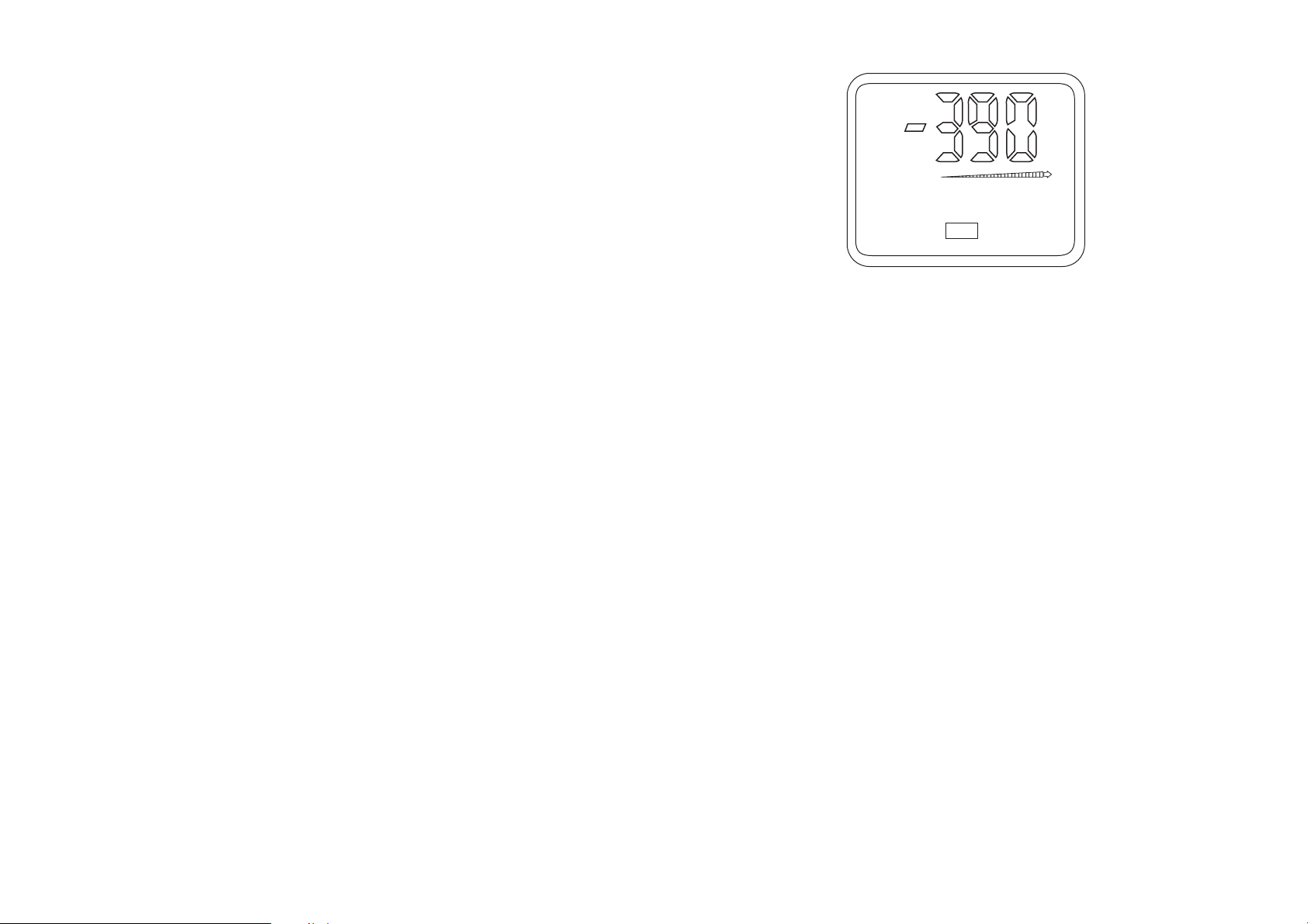
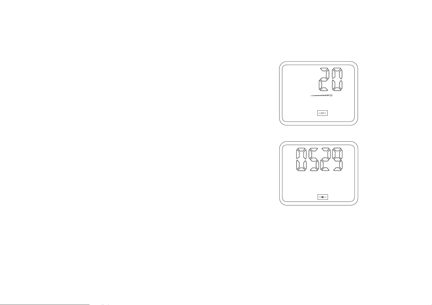
When a "-" appears in front of the DC voltage measured value, the measured voltage is negative (or the test leads are reversed).
Note!
1. During DC voltage measurement in addition to the measured value
only the bar graph is visible. None of the sub-displays is active. Note
also the following illustration.
Page 10

19
2 Selectable special functions
The following sub-functions, according to the model of multimeter,
are selectable via the "ENTER MENU" button:
"Æ%" reference value measurements, "MIN/MAX" value capture,
"TIME", "REC" record measured value, "RCLL" measured value recall,
"LMT" comparison function (VC 670 only) and "PH" peak value measurement (VC 650 and VC 670 only). These sub-functions are described in more detail in section 5.12.
5.4 Measurement of diodes and capacitors „->I- -I(-“
Attention
Discharge every capacitor before connecting it to the measuring instrument. When short-circuiting capacitors, high-energy discharges can
occur. T ake care in areas where dust, inflammable gas, fumes or liquid is
present or can occur. ==> Danger of explosions! Do not touch the
connectors of capacitors with voltages over 35 VDC or 25 V AC. Caution danger to life!
Carry out no measurements on capacitors built into circuits or parts of
circuits.
For the measurement of diodes and semi-conductors or capacitors up to
40 uF max. (VC 670up to 400 uF max., proceed as follows:
a) Switch on the measuring instrument. The initial configuration is
always AC voltage measurement in "AUTO" (automatic range selec-
AUTO
M½
½
0 +10 +20 +30
18
c) The bar graph beneath the measured value is active during measure-
ment, being similar to an analogue indicator with a faster reaction
time. The bar graph operates as a trend indicator.
d) Connect the test probes to the object to be measured, taking care
that it is voltage-free.
Note!
If resistors are to be measured which are built into a circuit in which
transistors/diodes are present, the test voltage of the 400-Ohm range is
sufficient to cause current to flow through these semiconductors. Hence
the measured values can be distorted.
The resistance of the test leads (some 0.1 to 0.2 Ohm) can normally be
ignored. However, even this low value can lead to inaccuracies in the
400 Ohm measurement area.
When resistance measurements are performed, take care that the measurement points which are to be touched with the test probes are free
from dirt, oil, solder flux or similar. Such conditions can distort the measured value.
Should "O.L" appear in the display, the measurement range has been
exceeded or the circuit being measured is open-circuited. Do not measure loaded capacitors, as a possible discharge may damage the measuring
instrument.
e) fBefore the acoustic/optical measurement of continuity up to 20 Ohm
max., press the "AC/DC" button once. The measuring instrument is
thereby switched from "½" measurement to „•))“.
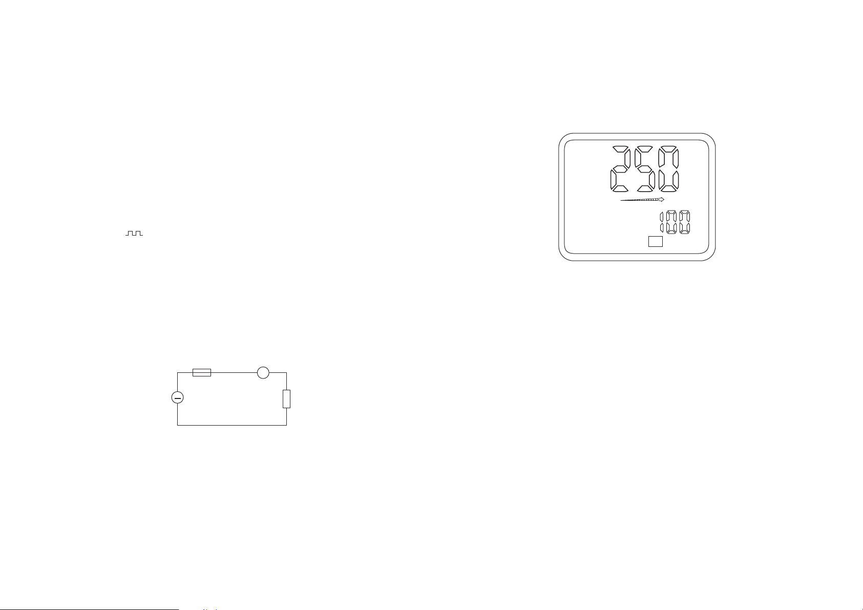
Note!
1. During resistance measurement/continuity test, other than the mea-
sured value only the bar graph is also present. None of the sub displays is active. Note also the following illustration.
Page 11
21
General note!
1. During capacity measurement and diode test, other than the measured value only the bar graph is also present. Note the following
illustration.
2. Selectable special functions
The following sub-functions, according to the multimeter model, are
selectable using the "ENTER MENU" button:
"Æ%" reference value measurements, "MIN/MAX" value capture,
"TIME", "REC" record measured value, "RCLL" measured value recall,
"LMT" comparison function (VC 670 only) and "PH" peak value measurement (VC 650 and VC 670 only). These sub-functions are described in
more detail in section 5.12.
AUTO
mV
AUTO
µF
0 +10 +20
20
tion) mode. Now press the „V•-I(-•½•->I-“ button twice. The measuring instrument switches to capacity measurement, recognisable
through the capacitor symbol at the bottom edge of the screen..
When the „V•-I(-•½•->I-“ button is pressed once again (ie. from the
base configuration, three times), diode test is reached, recognisable
through the diode symbol at the bottom edge of the screen.
b) For diode test, connect the black test lead to the "COM" socket of the
measuring instrument and the red test lead to the „V•½•Hz•Logic•-
>I-“ socket. When measuring capacity, only the measurement socket
adjacent to the "mAoTEMPoA" button on its right is to be used
("TEMP" present only on VC 650 and VC 670).
c) The bar graph beneath the measured value is active during measure-
ment, being similar to an analogue indicator with a faster reaction
time. The bar graph operates as a trend indicator.
d) Connect the test probes to the object to be measured, a diode, taking
care that it is voltage-free.
Note when measuring diodes!
Connect the test probes to the voltage-free semi-conductor component,
a diode or transistor. In this process, note that the red test lead must be
connected to the anode and the black test lead to the cathode. The forward conducting direction will now be measured. For an intact PN-junction in a silicon diode path, a value between 0.45 and 0.75 VDC appears,
while in a germanium diode path a value between 0.2 and 0.4 VDC
appears. If, however, instead of a voltage "O.L" (for overload) appears,
the diode path is open-circuit or the test leads reversed. If for transistors
a voltage of more than 1 V is measured, it can be that the transistor
incorporates resistors.
For light-emitting diodes, a forward voltage of approx. 1.4 up to 2.2
VDC will be measured. Where low current LEDs are concerned, the measurement current is sufficient to cause these to light.
The reverse direction of a diode path is measured with the red test lead
connected to the cathode and the black test lead to the anode. If as a
result of this a voltage value is indicated, the diode is faulty. If on the
contrary "O.L" is indicated, the diode path is high-impedance (O.K).
Page 12
23
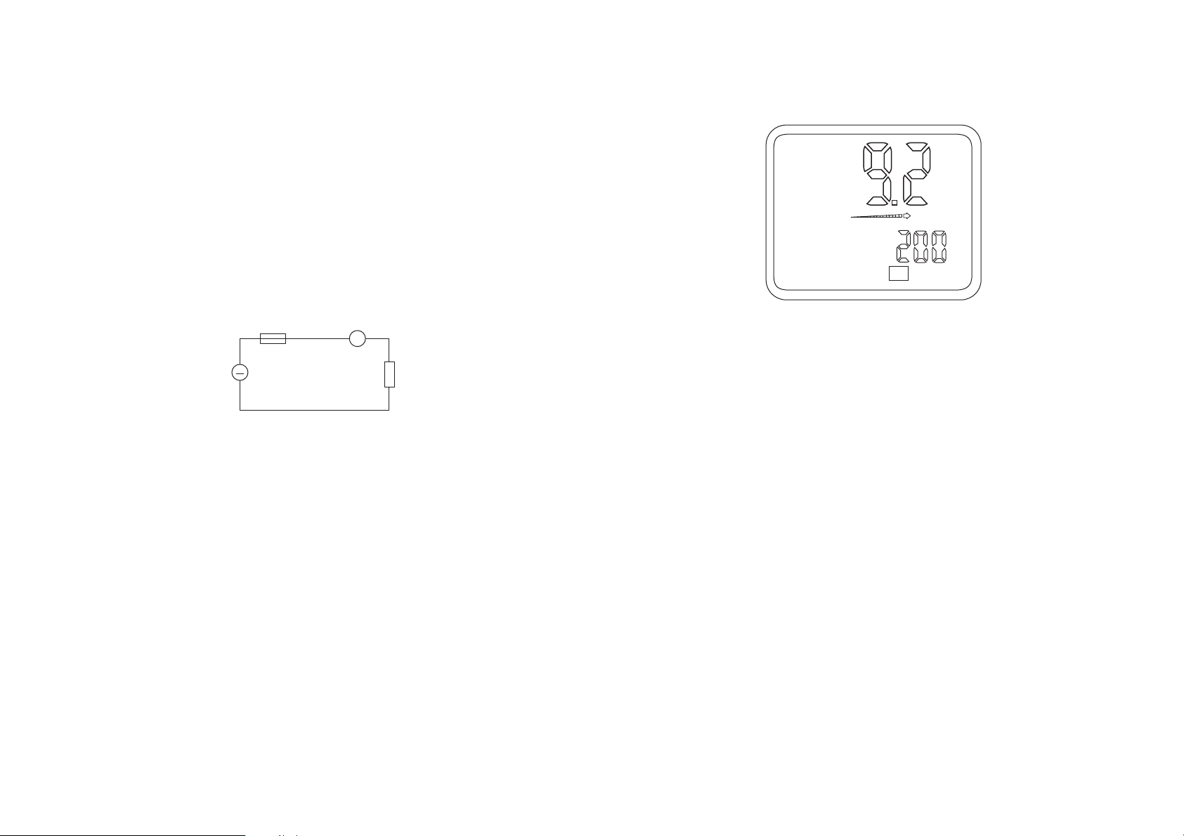
Note!
1. The frequency of the AC current is also indicated during AC current
measurement in addition to the measured value and the bar graph in
the bottom right of the sub-display ("small" display). In this connection, note the following illustration.
2. The VC 670 measures the true rms of an AC input. This type of mea-
surement is always useful where non-sinusoidal, overloaded, mixedfrequency or high frequency (switching power supply) signals are
concerned.
3. Selectable special functions
The following sub-functions, according to multimeter model, are selectable by means of the "ENTER MENU" button:
"Æ%" reference value measurements, "MIN/MAX" value capture,
"TIME", "REC" record measured value, "RCLL" measured value recall,
"LMT" comparison function (VC 670 only) and "PH" peak value measurement (VC 650 and VC 670 only). These sub-functions are described in more detail in section 5.12.
5.6 20 A DC and AC current measurement
For the measurement of DC or AC currents up to max. 20 A, proceed as
follows:
a) Switch the measuring instrument on. The initial configuration is
always AC voltage measurement in "AUTO" (automatic range selec-
AUTO
AC
mA
mA
Hz
0 +10 +20
22
5.5 mA DC and mA AC current measurement
For the measurement of DC and AC currents up to 400 mA max., proceed
as follows:
a) Switch the measuring instrument on. The initial configuration is
always AC voltage measurement in "AUTO" (automatic range selection) mode. Now press the „mA•TEMP•A“ once. The measuring
instrument switches to mA AC current measurement, recognisable
through the symbol "AC" adjacent to and to the left of the measured
value. For the measurement of DC currents up to 400 mA max. press
the "AC/DC" button once.
b) Connect the black test lead to the "COM" measuring instrument
socket and the red test lead to the "mA" socket (VC 630) or
„mA•TEMP• “ socket (VC 650 and VC 670).
c) The bar graph beneath the measured value is active during measure-
ment, being similar to an analogue indicator with a faster reaction
time. The bar graph operates as a trend indicator.
d) Connect the test leads in series with the object to be measured (see
following illustration).
Attention!
When a "-" appears in front of the DC current measured value, the measured current is negative (or the test leads are reversed).
Do not measure any currents in circuits in which voltages greater than
250 VDC or VAC rms can occur, otherwise as a result life can be endangered. Never measure currents over 400 mA. Measure currents equal to
or lower than 400 mA only in circuits themselves protected by a 400 mA
quick-blow fuse.
A
~
Fuse
Current
source
Measuring
instrument
Load
Page 13
25
in the bottom right of the sub-display ("small" display). In this
connection, note the following illustration.
2. The VC 670 measures the true rms of an AC input. This type of measurement is always useful where non-sinusoidal, overloaded, mixedfrequency or high frequency (switching power supply) signals are
concerned.
3. Selectable special functions
The following sub-functions, according to multimeter model, are selectable by means of the “ENTER MENU” button
#“Æ%” reference value measurements, “MIN/MAX” value capture,
“TIME”, “REC” record measured value, “RCLL” measur ed value recall,
“LMT” comparison function (VC 670 only) and “PH” peak value measurement (VC 650 and VC 670 only). These sub-functions are described in more detail in section 5.12.
5.7 Temperature measurement (VC 650 and VC 670 only)
The temperature measuring range of the digital multimeter extends
from -40°C to +1000° C. Temperature measurement is carried out
exclusively using a K-type thermocouple probe. It should be noted that
outside the temperature range +18°C to + 28°C (= range of guaranteed
measurement accuracy) only the thermocouple should be placed within
the temperature to be measured. Additionally, the temperature
AUTO
AC
A
A
Hz
0 +10 +20
24
tion) mode. Now press the „mA•TEMP•A“ button twice. The measuring instrument switches to A AC current measurement, recognisable
through the symbol "AC" to the left and adjacent to the measured
value. For the measurement of DC currents up to 20 A max., press the
"AC/DC" button once.
b) Connect the black test lead to the "COM" measuring instrument
socket and the red test lead to the "20 A" socket.
c) The bar graph beneath the measured value is active during measure-
ment, being similar to an analogue indicator with a faster reaction
time. The bar graph operates as a trend indicator.
d) Connect the test leads in series with the object to be measured (see
following illustration).
The "RANGE" button (manual range selection) is without function
during A current measurement.
Attention!
When a "-" appears in front of the DC current measured value, the measured current is negative (or the test leads are r eversed). Never measure
currents over 400 mA. Measure currents equal to or lower than 400 mA
only in circuits themselves protected by a 400 mA quick-blow fuse.
Never measure currents over 20 A. Measure only in circuits themselves
fused at 20 A and in which no powers greater than 4000 VA can occur.
Measurements of currents equal to 20 A may be of 30 s duration max.
and be carried out only at intervals of 15 minutes (shunt cooling phase).
Note!
1. During AC current measurement, indicated in addition to the measured value and the bar graph, the frequency of the AC current is also
A
~
Fuse
Current
source
Measuring
instrument
Load
Page 14

27
(“small” display) the temperature in “°F” is also indicated. Note the
following table.
2. Selectable special functions
The following sub-functions, according to multimeter model, are
selectable by means of the “ENTER MENU” button:
“Æ%” reference value measurements, “MIN/MAX” value capture,
“TIME”, “REC” record measured value, “RCLL” measur ed value recall,
“LMT” comparison function (VC 670 only) and “PH” peak value measurement (VC 650 and VC 670 only). These sub-functions are described in more detail in section 5.12.
5.8 Frequency measurement
a) Switch the measuring instrument on. The initial configuration is
always AC voltage measurement in “AUTO” (automatic range selection) mode. Now press the „Hz•hfe• •Logic“ button once. The measuring instrument switches to frequency measurement, recognisable
through the symbol “Hz” in the bottom left of the display and
through the display of period in ms in the left sub-display and voltage in V in the right-hand sub-display. In addition the symbol “TRIG”
with “+” or “-” appears to the left beneath the measurement value.
b) Connect the black test lead to the “COM” measuring instrument
socket and the red test lead to the „V•½•Hz•Logic•->I-“ socket.
c) The bar graph beneath the measured value is active during measu-
rement, being similar to an analogue indicator with a faster reaction
time. The bar graph operates as a trend indicator.
AUTO
¡C
¡F
TEMP
0 +10 +20
26
measuring set is available optionally and is therefore not among the
standard items supplied. If no thermocouple is connected to the
measuring instrument, the current room temperature is automatically
measured and displayed (in °C and °F).
To perform a temperature measurement, proceed as follows:
a) Switch the measuring instrument on. The initial configuration is
always AC voltage measurement in “AUTO” (automatic range selection) mode. Now press the “mA•TEMP•A” button three times. The
measuring instrument switches to temperature measurement, recognisable through the symbol “TEMP” at the bottom right of the display and by the display of the temperature in degrees C and in the
sub-display in degrees F.
b) Insert the thermocouple plug correctly polarised (smaller and wider
contacts) into the temperature adapter and connect this correctly
polarised (observe “+” and “-”) into the “COM” (=“-“) and
„mA•TEMP• „ (=“+“) sockets.
c) The bar graph beneath the measured value is active during measure-
ment, being similar to an analogue indicator with a faster reaction
time. The bar graph operates as a trend indicator.
d) Connect the thermocouple probe to the voltage-free object to be
measured. Hold the temperature probe on/in the object to be measured until the DMM display has stabilised (approx. 30 s).
Attention!
Do not connect any voltages. The instrument can be destroyed by this.
Note !
1. During temperature measurement, in addition to the measured
value and the bar graph in the bottom right of the sub-display
Page 15
29
“Æ%” reference value measurements, “MIN/MAX” value capture,
“TIME”, “REC” record measured value, “RCLL” measur ed value recall,
“LMT” comparison function (VC 670 only) and “PH” peak value measurement (VC 650 and VC 670 only). These sub-functions are described in more detail in section 5.12.
5.9 Transistor test
Attention !
The transistor socket is not protected against overload.
To measure the hFE parameter (amplification) of a transistor, proceed as
follows:
a) Switch the measuring instrument on. The initial configuration is
always AC voltage measurement in “AUTO” (automatic range selection) mode. Now press the „H•hfe• • Logic“ button three times.
The measuring instrument switches to transistor test, recognisable
through the symbol “hfe” in the bottom left of the display.
b) The bar graph beneath the measured value is active during measure-
ment, being similar to an analogue indicator with a faster reaction
time. The bar graph operates as a trend indicator.
c) Place the transistor to be tested into the measurement socket. Obser-
ve the pin configuration (e.g. c-b-e) of the item to be measured
(given in transistor comparison tables/lists).
Note the following:
- some types of transistor include base-emitter resistors, which can
distort the measurement result.
- the measured hfe value is not absolutely accurate. It only confirms
whether the transistor is working or not. The actual amplification of a
transistor depends on its working current. This multimeter can deliver
a base current up to 10 uA with a Vce of 2.8 V. The collector current
flowing during measurement is captured and from this the hFE value
is calculated.
28
d) Connect the black test lead (test probe) to the circuit or signal gene-
rator earth and the red test lead (test probe) to the signal to be measured.
Attention!
It is essential to observe the maximum input levels! Do not connect any
voltages greater than 250 VDC or VAC rms max. Life can be endangered
by coming into contact with voltages greater than 25 VAC or 35 VDC.
Do not switch to another measuring function or to another range
during measurement.
Switching under voltage (high energy) can cause a disconnection arc,
which can irrevocably destroy the printed circuit tracks inside the measuring instrument. In addition, life may be endangered as a result of
damage to the measuring instrument.
Frequency measurement is not possible with voltages smaller than
approx. 50 mV rms (measured at 1 KHz).
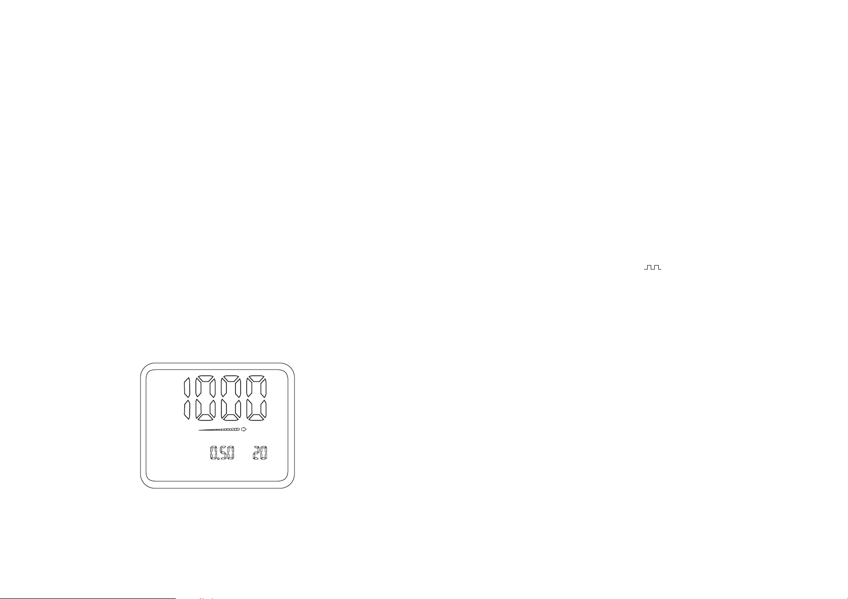
Notes!
1. During frequency measurement, in addition to the measured value
and the bar graph, in the bottom right sub-display (“small” display)
the level (amplitude) of the measured voltage in VAC rms is also displayed; in addition the 1/2 period (1/2 reciprocal of the frequency) of
the signal being measured (up to 100 kHz) appears in the left sub-display. Note the following table.
2. Selectable special functions
The following sub-functions, according to multimeter model, are
selectable by means of the “ENTER MENU” button:
AUTO
Hz
0 +10 +20
ms
mV
Page 16

31
- if the test point shows a level between 30% and 70% of Vcc, then “--
-” appears in the display
To establish the logic level or to set the level ranges, proceed as follows:
a) Switch the measuring instrument on. The initial configuration is
always AC voltage measurement in “AUTO” (automatic range selection) mode. Now press the „Hz•hfe• •Logic“ button four times.
The measuring instrument switches to logic test, recognisable
through the symbol “Logic” at the bottom of the display and through
the display of the voltage in V in the centre of the sub-display and of
the frequency in kHz on the right of the sub-display. Additionally, to
the left of the voltage indication “t” can be seen with the TTL level,
with “CMOS 3V” => “3C” and with “CMOS 5V” => “5C”.
b) Connect the black test lead to the “COM” measuring instrument
socket and the red test lead to the „V•½•Hz•Logic•->I-“ socket.
c) The bar graph beneath the measured value is active during measure-
ment, being similar to an analogue indicator with a faster reaction
time. The bar graph operates as a trend indicator.
d) Now connect the other end of the black test lead (test probe) to the
“earth” of the digital circuit, normally “-”.
e) While the black test lead remains connected to “earth”, touch the
points to be tested with the red test probe.
5.11 Use as signal generator (not VC 630)
The DMM incorporates a sort of “function generator”, which delivers
from the centre measurement socket a frequency variable between the
limits 1 Hz and 5 (5.041) kHz at the fixed level of 5V.
T o output a TTL level at a frequency variable within these limits, proceed
as follows:
a) Switch the measuring instrument on. The initial configuration is
always AC voltage measurement in “AUTO” (automatic range selection) mode. Now press the„Hz•hfe• •Logic“ button twice. The
30
- no transistor can be measured which is incorporated into a circuit.
- the hfe values of FETs or other unipolar transistors cannot be measured with this multimeter.
- when the connecting “legs” of the item to be measured do not fit
into the socket (too “fat”), do not use force, otherwise the socket can
thereby be damaged.
- the measurement of hfe reacts to temperature variations. As soon as
the transistor is picked up and plugged into the connector and warmed with the fingers, the measured value can alter . If an unstable display occurs, remove the transistor and allow it to cool down to room
temperature.
Notes!
1. During transistor tests, in addition to the measured value only the
bar graph is also displayed. The sub-displays are not active.
2. Selectable special functions
The following sub-functions, according to multimeter model, are selectable by means of the “ENTER MENU” button:
“Æ%” reference value measurements, “MIN/MAX” value capture,
“TIME”, “REC” record measured value, “RCLL” measured value recall,
“LMT” comparison function (VC 670 only) and “PH” peak value measurement (VC 650 and VC 670 only). These sub-functions are described in more detail in section 5.12.
5.10 Logic test (not VC 630)
This measurement function is used to establish the logic levels in digital
circuits (27-TTL, 3 V or 5 V logic and others). With this logic function the
following conditions can be determined:
- if the test point shows a high level greater than 70 % of Vcc then “Hi”
appears in the display.
- if the test point shows a low level, smaller than 30 % of Vcc, then
“Lo” appears in the display.
Page 17

33
tions is selected, the selection disappears automatically after
approx. 6 s.
b) “Æ%” reference value measurement
The reference value measurement, represented by a delta and percent symbol, enables measurements with reference to a previouslyset value. This set value appears then unchanged in the right-hand
sub-display. Adjacent and to the left, the difference value in percent is indicated in the centre sub-display; in the main display the
instantaneous actual measured value appears. This function is particularly well-suited to resistance measurement. The display can be
set to “0000”, meaning that resistance measurements can be carried out in the low ohms range without the need to deduct the
resistance of the test leads from the measured value each time.
Reference value measurement is possible during voltage, current,
resistance, capacity and temperature measurement (temperature
with VC 650 and VC 670 only). Because “AUTO”-ranging is switched
off during reference value measurement, the desired measurement
range must be set manually prior to using this special function.
To set the reference value, proceed as follows:
Set the desired measurement range (by means of the “RANGE”
button). Measure the required reference value, e.g. a DC voltage of
12 VDC. Press the “ENTER MENU” button once. The menu appears
in the top line. Within 6 seconds, press the “ENTER MENU” button
once again. The first of the special functions, “Æ%”, is set. The reference value “12 VDC” is displayed in the right-hand small display
(sub-display).
5.13 “MIN/MAX” value-capture sub-function
When the highest- (= “MAX”) and the lowest- (= “MIN”) occurring
measured value of a steadily-changing measured level is to be captured
then, during the measurement, press the “ENTER MENU” button. The
menu appears in the top line. The first symbol (for reference value
measurement) flashes. Using the “< >” button, move from symbol to
symbol. Press this button until the “MIN/MAX” symbol flashes. Finally
press the “ENTER MENU” button again. The flashing ceases and the
“MIN/MAX” value-capture is started.
32
measuring instrument switches to signal generator output, recognisable through the symbol „ “ at the bottom left of the display.
b) Connect the black test lead to the “COM” measuring instrument
socket and the red test lead to the „mA•TEMP• “ socket of the
VC 650 or VC 670.
c) Although the bar graph appears under the display of the output fre-
quency, it is however not here as trend indicator.
d) Connect the test probes to the object to be measured and, when
necessary, operate the following buttons to set the output frequency:
Each operation of the “<” button (under “Enter”) reduces the output
frequency by one step. Each operation of the “>” button (under “Enter”)
increases the output frequency by one step.
Attention!
Do not short-circuit the signal generator output of the measuring instrument, because the unit can be destroyed by this.
Connect no voltage to the signal generator output of the measuring
instrument, because the unit can similarly be damaged or destroyed.
Note !
Selectable special functions
The following sub-function is selectable by means of the “ENTER MENU”
button: “TIME”. The sub-functions are described in more detail from
section 5.12.
5.12 General and “Reference value measurement” sub-function
a) General
The following chapters describe the special functions which are to
be seen at the top of the LCD display after the “ENTER MENU” button is pressed. According to the measuring instrument model, more
or fewer function symbols appear. When none of the special func-
Page 18

35
To set the limits, proceed as follows:
First set the desired measurement range manually by means of the
“RANGE” button. Press the “ENTER MENU” button. The menu appears in
the top line. The first symbol (for reference value measurement) flashes.
Using the “< >” button, move from symbol to symbol. Press this button
until the symbol “LMT” flashes. Confirm the selection with the “ENTER”
button. As a result of this, three sub-displays appear. In the left subdisplay the current measured value is indicated. The centre sub-display
shows the upper limit and the right sub-display shows the lower limit.
The right sub-display flashes. Now press the button “< >” by pressing the
right (+) or left (-) button edge until the desired lower limit is shown.
Confirm by pressing the “ENTER” button. The centre sub-display flashes.
Proceed with setting the upper limit as for the lower. Press the “ENTER”
button once in confirmation. Depending on the level of the measured
value, “PASS” is now displayed when the measured value lies between
the upper and lower limits. “LO” is displayed when the measured value is
lower than the set lower limit. “HI” is displayed when the measured
value is higher than the upper set limit.
5.16 “PH” peak hold measurement sub-function (not VC 630)
With the peak hold function, the highest-occurring measured value is
captured and indicated. Press the “ENTER MENU” button. The menu
appears in the top line. The first symbol (for reference value
measurement) flashes. Using the “< >” button, move from symbol to
symbol. Press this button until the symbol “PH” flashes. Confirm the
input with the “ENTER” button. The peak value captured within
milliseconds (ms) is displayed in the centre sub-display. The currentlymeasured value can be read in the main display. To exit the “PH”
function, press the “ENTER MENU” button once briefly or press the
“AC/DC” button or one of the measurement function buttons around
the “ENTER MENU” button => the relevant screen appears.
5.17“REC” record measured value and “RCLL” recall measured
value sub-functions
Up to 10 measured values can be stored and recalled by means of the
sub-functions “REC” (record) and “RCLL” (recall). The measured values
34
Clearly and above all simultaneously, the instantaneously-measured
value, the maximum value (centre sub-display) and the minimum value
(right sub-display) are now displayed on the whole screen area.
To exit the “MIN/MAX” function, press the “ENTER MENU” button once
briefly or the “AC/DC” button or one of the measurement function
buttons around the “ENTER MENU” button => the relevant screen
appears.
5.14 “TIME” (time-capture) sub-function
During measurement a clock can be started by means of the “TIME”
function, which records the time from the start of measurement. The
time stored is 24 hours maximum. Until one hour has elapsed, the time is
presented in minutes and seconds, thereafter in hours and minutes.
To set the clock, proceed as follows:
During or prior to measurement press the “ENTER MENU” button. The
menu appears in the top line. The first symbol (for reference value
measurement) flashes. Using the “< >” button, move from symbol to
symbol. Press this button until the “TIME” symbol flashes. Confirm the
selection with the “ENTER” button. The clock is displayed in the left subdisplay . The clock can be started and stopped and reset to zero using the
“< >” button. Pressing once on the left arrow (left button edge) stops or
starts the clock. Pressing once on the right arrow (right button edge)
resets the clock to zero. To exit the “TIME” function, press the “ENTER
MENU” button once briefly or press the “AC/DC” button or one of the
measurement function buttons around the “ENTER MENU” button =>
the relevant screen appears.
5.15 “LMT” comparison value measurement sub-function
(VC 670 only)
So-called comparison measurements are possible by means of the “LMT”
(limit) function. High/low comparisons can be made in this sub-function,
in which the instantaneously-measured value is compared with the
highest and lowest reference values stored. To exit the “LMT” function,
press the “ENTER MENU” button once briefly or press the “AC/DC”
button or one of the measurement function buttons around the “ENTER
MENU” button => the relevant screen appears.
Page 19

37
2. Having established the connection, switch on the measuring instrument by means of the “POWER” switch.
3. Press the “HOLD” button (approx. 3 seconds) until the circle symbol
with a “2” appears on the right beneath the main display.
4. Now switch the PC (“computer”) on.
5. Use of Windows software (optionally available):
Attention!
The following steps presuppose basic knowledge of MS Windows. In
case of difficulty, study the Windows manual concerning the use of
WINDOWS.
Windows 95 and a VGA monitor are required for the operation of this
software.
a) Start the computer and activate Windows.
b) Load the diskette into the appropriate 3.5" drive (“a” or “b”).
c) With the mouse, click the “START” button and then click “Run”.
As a result of this, the Run dialog box with command line opens.
d) Enter the following at the flashing cursor:
When the diskette is in drive “a” : type a:\setup and press
[Enter] or click “OK”
When the diskette is in drive “b” : type b:\setup and press
[Enter] or click “OK”
e) Follow the on-screen directions to complete the installation.
f ) To start the program, with the left mouse button double-click
the program “Multimeter” and then follow the on-screen
instructions.
T ake note also of the “README” file on the diskette for remarks
concerning operating.
36
remain stored even after the measuring instrument has been switched
off.
To record a measured value, proceed as follows:
Press the “ENTER MENU” button. The menu appears in the top line. The
first symbol (for reference value measurement) flashes. Using the “< >”
button, move from symbol to symbol. Press this button until the symbol
“REC” flashes. Confirm the input with the “ENTER” button. The
measuring instrument is now ready to record. Press the right edge (“>”)
of the “< >” button to select the memory location (from 0 to 9).
Pressing the left edge of the button stores the measured value; each
time the left edge of the button is pressed again, the same memory
location is overwritten. The number of the current memory location is
indicated on the left adjacent to the sub-display.
To recall the stored measurement value, proceed as follows:
Press the “ENTER MENU” button. The menu appears in the top line. The
first symbol (for reference value measurement) flashes. Using the “< >”
button, move from symbol to symbol. Press this button until the symbol
“RCLL” flashes. Confirm the input with the “ENTER” button. The
memory locations are called in reverse order (9 => 0) each time the left
edge of the “< >” button is pressed. Each time the right edge of the “<
>” button is pressed, the memory locations are called in increasing
order (0 => 9). To exit the function press the “ENTER” button.
5.18 Connecting the measuring instrument to a computer
Attention!
Data transfer takes place unidirectionally, i.e. only in one direction: from
the measuring instrument to the PC and not vice versa
The following steps are required for communication between an (IBM
compatible) PC and the measuring instrument:
1. Connect the optionally-available interface cable on the one hand
with the 5-pin asymmetrical socket on the measuring instrument
and on the other hand to the PC.
Page 20

39
attacked. Additionally, the fumes are explosive and damaging to health.
When cleaning, also use no sharp-edged tools, screwdrivers or metal
brushes or similar.
6.2 A 9 V battery is required to operate the measuring instrument. The battery should be changed when the batterychange symbol appears in the display. For this, proceed as
follows:
- disconnect the measuring instrument from the circuit being
measured,
- remove the test leads from the measuring instrument,
- switch the unit off and
- with a suitable cross-head screwdriver, unscrew the fixing screws
at the top centre and at the bottom left and right of the lower
case shell.
- now carefully lever off the lower case shell.
- wearing disposable gloves, remove the used battery and dis-
connect it from the connecting clips.
- taking a new, unused battery, connect the connecting clips to
the correctly-polarised battery and place it in the battery
compartment.
- having successfully inserted/changed the battery, carefully close
the case again. Take care not to trap the connecting clip leads
during re-assembly.
Attention!
Never operate the measuring instrument in an opened condition! Danger to life!
Never leave an exhausted battery in the measuring instrument, because
even “leak-proof” batteries can corrode and thereby release chemicals
which can endanger health or destroy the battery compartment.
6. Note the following if other software is to be used:
The data format is 14 bytes long. The sequence is as follows:
BYTE 1 2 3 4 5 6 7 8 9 A B C D E
Example 1 DC - 3 . 9 9 9 V CR
Example 2 AC 3 9 9 . 9 m V CR
Program example in BASIC simply to read the multimeter:
10 OPEN “COM1:4800, N, 7, 2, RS, CS, DS, CD“ AS #2
20 IN$=INPUT$(14, #2)
30 PRINT IN$
40 CLOSE #2
50 END
Data transfer parameters (communication parameters):
Transfer rate : 4800 baud (= bps = bits per second)
Character code : 7-bit ASCII
Parity : keine
Stop bits : 2
6. Maintenance, changing the battery, changing the fuse, positioning the measuring
instrument
6.1 Maintenance
To guarantee the accuracy of the VC 630 / 650 / 670 multimeters longterm, calibration should be carried out once yearly, possibly in our
service centre (S-2000).
Fitting/changing the battery is described in section 6.2; changing the
fuse is described in 6.3. To clean the unit and its display window and the
test leads, use a dry, clean, lint-free, anti-static cloth.
Attention!
Use no carbonaceous cleaning fluids nor petrol, alcohol or similar for
cleaning, otherwise the surface of the measuring instrument may be
38
Page 21

41
Remove the defective fuse(s) and replace these with identical types and
nominal current ratings.
For fuse F1 (for the mA-range): 0.5 A, quick-blow, 250 V; usual
description: F0.5A/250 V or F500mA/250V (size: 5 x 20 mm).
For fuse F2: 20 A, quick-blow, 250 V; usual description: F20A/250 V (size:
6.3 x 32 mm). To fit/replace the 20A fuse, the printed circuit board must
be removed. The fuse holder can be found on the component side of the
PCB.
Having successfully changed the fuse(s), carefully close and screw the
case once more, in reverse order.
Only put the measuring instrument into operation once again when the
case is securely closed and screwed.
6.4 Positioning (inclining) the measuring instrument
On the rear of the measuring instrument case is a fold-out stand. Using
this, the measuring instrument can be placed into an inclined position,
facilitating readings.
7. Technical data and measurement tolerances
7.1 Technical data
Display.......................................: 3 3/4-digit (3999) LCD (liquid crystal
display) and two (simultaneous) subdisplays with VC 630 and VC 650, or 3
(simultaneous) sub-displays with VC
670.
Frequency of measurements...: Digital indicator; 4 measurements per
second
Bar graph indicator; 7 measurements
per second
Input resistance........................: Greater than 10 MOhm
Back-lighting.............................: (VC 670 only) 60 s max. (current
consumption approx. 30 mA)
Auto power off.........................: after approx. 30 minutes
Incorrect button pressed..........: “E.r.r” possible, with continuous
acoustic tone (switch off and on again)
40
Used batteries are to be treated as waste requiring special handling and
must therefore be disposed of without harming the environment. Special collection bins are provided for this purpose at specialist retailers and
in waste-recovery yards..
6.3 Changing the fuses
Observe the safety instructions without fail when changing fuses!
Make sure that only fuses of the given types and nominal current ratings
are used as replacements. The use of repaired fuses or the bridging of
fuse holders is not permitted. To change the fuses, disconnect the
measuring instrument from the circuit being measured and switch it off.
Remove all connected leads, adapters and test probes. Take a suitable
cross-head screwdriver and carefully open the case (refer also to 6.2
Changing the battery).
In this connection, note the following illustration:
Opening the unit and location of fuses F1 and F2
F1
F2
F2 = 20 A
F1 =500 mA
Page 22
4342
Change-battery symbol.....: From lower than 7.5 VDC ±0.5 V
Acoustic warning signal....: Interrupted tone at voltages above
700 VAC rms and 1000 VDC
Battery required.................: 9 V battery type NEDA 1604 6F22 or 006P
or 6LR61
Operating temperature.....: 0°C to +40°C with relative humidity
< 70%, non-condensing
Storage temperature.........: -20°C to +60°C with relative humidity
< 80 %, non-condensing (battery removed)
Temperature for guaranteed
accuracy..............................: +23°C ±5 K (= Kelvin)
Weight................................: approx. 350 g (without battery, without
test leads)
Dimensions (L X W X H).....: 178 x 88 x 33 mm (stand folded away,
without test leads)
7.2 Measurement tolerances
Accuracy specified in ±(% of reading + number of digits)
Accuracy over one 1 year duration at a temperature of +23°C ±5 K, at a
relative humidity of less than 80 %, non-condensing. The warm-up time
is 1 minute.
Operation mode Measurem. range Accuracy Resolution
DC voltage 400 mV ±(0,5%+5dgts) 0,1 mV
4 V ±(0,3%+5dgts) 1 mV
40 V ———“——— 10 mV
400 V ———“——— 100 mV
1000 V ———“——— 1 V
Overload protection: 1000 VDC less than 10 s
Input resistance in 400 mV range: 100 MOhm
Only VC 630: ±(0,5%+5dgts) in all ranges
AC voltage 400 mV not specified 0,1 mV
4 V ±(1,0%+10dgts) 1mV
only VC 630 650 40 V ———“——— 10 mV
and VC 400 V ———“——— 100 mV
AC voltage frequency : 50 Hz à 500 Hz
Input resistance when measuring voltage (AC and DC, except mV range)>
10 MOhm
Overload protection: 700 VAC rms less than 10
Operation mode Measurem. range Accuracy Resolution Frequency
DC voltage
True RMS 4 V ±(1,5%+10dgts) 1mV 20 Hz to 50 Hz
±(1,0%+10dgts) 1mV 50 Hz to 500 Hz
±(2,5%+10dgts) 1mV 500 Hz to 5 kHz
±(5,0%+20dgts) 1 mV 5 kHz to 10 kHz
only VC 670 40 V ±(1,5%+10dgts) 10mV 20 Hz to 50 Hz
±(1,0%+10dgts) 10mV 50 Hz to 500 Hz
±(2,5%+10dgts) 10mV 500 Hz to 5 kHz
±(5,0%+20dgts) 10 mV 5 kHz to 10 kHz
400 V ±(1,5%+10dgts) 100mV 20 Hz to 50 Hz
±(1,0%+10dgts) 100mV 50 Hz to 500 Hz
±(2,5%+10dgts) 100mV 500 Hz to 5 kHz
±(5,0%+20dgts) 100 mV 5 kHz to 10 kHz
700 V ±(1,5%+10dgts) 1V 20 Hz to 50 Hz
±(2,0%+10dgts) 1V 50 Hz to 500 Hz
±(2,0%+10dgts) 1V 500 Hz to 5 kHz
not specified 5 kHz to 10 kHz
DC current 40 mA ±(1,2%+5dgts) 10 uA
VC 630/650/ 400 mA ±(1,2%+5dgts) 100 uA
670 20 A ±(1,5%+5dgts) 10 mA
Overload protection, see 8.3
AC current 40 mA ±(2,0%+10dgts) 10uA 20 Hz to 50 Hz
VC 630/650/670 ±(1,2%+10dgts) 10uA 50 Hz to 500 Hz
±(4,0%+10dgts) 10uA 500 Hz to 5 kHz
400 mA ±(2,0%+10dgts) 100uA 20 Hz to 50 Hz
±(1,2%+10dgts) 100uA 50 Hz to 500 Hz
±(4,0%+10dgts) 100uA 500 Hz to 5 kHz
20 A ±(2,5%+10dgts) 10mA 20 Hz to 50 Hz
±(1,5%+10dgts) 10mA 50 Hz to 500 Hz
±(4,0%+10dgts) 10mA 500 Hz to 5 kHz
only VC 670: True RMS - current measurement in all ranges
Resistance 400 ½ ±(0,75%+5dgts) 0,1 ½
4 k ½ ———“——— 1 ½
40 k ½ ———“——— 10 ½
400 k ½ ———“——— 100 ½
4 M ½ ———“——— 1 k ½
40 M½ ±(3,0%+5dgts) 10 k½
only VC 670 400 M½ ±(5,0%+5dgts) 100 k½
Page 23
45
Multimètres numériques VC 630, VC 650, VC 670 TRUE RMS
Attention! A lire absolument!
Veuillez lire la présente notice d'emploi avec la plus grande attention.
En cas de dommages qui seraient la conséquence du non-respect de la
présente notice d'emploi, vous perdez tout droit à dédommagement, la
garantie n'étant plus applicable; vous courez, en outre, un danger de
mort en cas de non-respect de la notice d'emploi! Nous n'assumons
aucune responsabilité pour tous dommages consécutifs. De bonnes connaissances de base pour l'utilisation d'appareils de mesure et d'ordinateurs sont indispensables. Veuillez conserver cette notice d'emploi avec
soin.
Table des matières
Page
1. Utilisation conforme ............................................................................ 45
2. Introduction........................................................................................... 46
3. Consignes de sécurité............................................................................ 47
4. Description des fonctions des éléments
de commande (introduction à l'aide des touches).............................. 51
5. Description des fonctions de mesure .................................................. 57
6. Entretien, échange de la batterie, échange des fusibles,
mise en place des instruments de mesure ........................................... 84
7. Caractéristiques techniques et tolérances de mesure......................... 87
1. L'utilisation conforme des instruments de
mesure comprend:
• Mesure de tensions continues jusqu'à une valeur maximale de
1000 VDC
• Mesure des tensions alternatives jusqu'à une valeur maximale de
700 VACrms
F
44
7.3 Maximum input levels
Current
measurement : 20 A AC / DC in the A range, 30 seconds duration max.
with an additional cooling phase of at least 15 min.,
250 VDC / VAC rms max., overload protection: 20 A
250 V quick-blow ceramic fuse (size: 6 x 30 mm);
500 mA AC/DC in the mA range, 250 VDC/VAC rms
max., overload protection: 0.5A 250V quick-blow ceramic fuse (size: 5 x 20 mm)
Attention!
The diode test, transistor test, logic test, "SIG OUT" (signal generator
output), capacity measurement and temperature measurement functions
are not protected against overload or excessive input voltage(s).
Exceeding the maximum permitted input level can lead to damage to the
measuring instrument and can endanger the life of the user.
Operation mode Measurem. range Accuracy Resolution Frequency
Continuity check: an acoustic signal sounds in the case of resistances < 20 Ohm
Capacity 4 nF ±(3,0%+10dgts) 1 pF
40 nF ———-“——— 10 pF
400 nF ———“——— 100 pF
4 uF ———“——— 1 nF
40 uF ———“——— 10 nF
only VC 670 400 uF ±(5,0%+20dgts) 100 nF
Diode control Ge à GaAs ±(2,0%+5dgts) 1 mV
Test current 1 mA max.; forward voltage max. 5,0 V
Temperature measurem.: up to 150°C ±(3,0%+5dgts) 1°C
> 150°C ±3,0% 1°C
Frequency 4 kHz ±(0,1%+10dgts) 1 Hz
40 kHz ———“——— 10 Hz
400 kHz ±(0,1%+10dgts) 100 Hz
4 MHz ———“——— 1 kHz
Sensitivity greater than or equal to approx. 50 mVeff 1 Hz to 4 MHz
Sensitivity during current measurement: in 40mA range , 5 mA
in 400 mA range, 5 mA
in 20 A range, 5 A
Signal generator output:
The TTL level is adjustable from 1 Hz to 5 (5,041) kHz; the amplitude is a fixed 5 V
Page 24

47
tions. Le commutateur rotatif habituel nécessaire à l'ajustage de la fonction de mesure manque totalement. Ceci évite une usure des contacts ou
autres problèmes liés au commutateur. Avec le modèle de base VC 630,
en dehors des mesures habituellement réalisables avec une multimètre,
le contrôle de transistors, les mesures de fréquences et les mesures de
capacité sont possibles. Avec VC 650, on pourra en plus effectuer des
mesures de température (à l'aide de l'adaptateur disponible en option)
et des vérifications logiques. De plus un générateur de signaux TTL est
installé. La fréquence de sortie se situe entre 1 Hz et 5 kHz.
Enfin, le VC 670 est conçu comme multimètre T rue rms. True rms signifie,
que le multimètre indiquera toujours pour des grandeurs alternatives
(courants et tensions) indépendamment de la forme de la courbe du signal de mesure, la valeur effective réelle (True = réel; rms = effectif) du
signal de mesure. De plus, il existe les possibilités suivantes par rapport
au VC 650: mesures de capacités jusqu'à max. 400 uF, mesures de tensions alternatives True-rms jusqu'à 700 VAC, mesures de courants alternatifs True-rms jusqu'à max. 20 A et des mesures de résistances jusqu'à
max. 400 Mohms. De plus le DMM VC 670 possède un éclairage de fond
commutable et un indicateur acoustique de la valeur mesurée (TONE):
selon la hauteur du signal de mesure un signal acoustique plus ou moins
élevé se fait entendre.
Tous les trois multimètres numériques possèdent un interface sériel par
lequel une communication avec un ordinateur devient possible. Le logiciel (disquette) et la hardware nécessaire en complément (câble interface) sont disponibles en options. Si l'appareil de mesures n'est pas utilisé
pendant plus de 30 min., la fonction AUTO-POWER-OFF arrête l'appareil
de mesures. Les multimètres sont d'usages universels pour les applications qui relèvent du bricolage (hobby), ainsi que de la profession (usage
industriel à exclure) ou scolaires.
3.Consignes de sécurité
• Les multimètres numériques VC 630, VC 650 et VC 670 TRUE RMS sont
contrôlés EMV et en ce qui concerne la sécurité (CE pour l'usage ménager et professionnel, pas pour un usage industriel) et répondent aux
directives EMV 89/336/CEE respectivement aux directives relatives aux
basses tensions 73/23/CEE.
• Ces appareils sont construits selon VDE 0411 partie 1 = NE respective-
ment IEC 61010-1, mesures de sécurité pour appareils de mesures élec-
46
• Mesure de courants continus et alternatifs jusqu'à max. 20 A
• VC 670: TRUE RMS - Mesures de courants alternatifs jusqu'à max. 20 A
et mesures de tensions alternatives jusqu'à max. 700V AC rms
• VC 630 et VC 650: mesure de condensateurs jusqu'à max. 40 uF; VC 670
jusqu'à 400 uF
• Mesure de fréquences jusqu'à max. 4 MHz
• VC 630 et VC 650: Mesure des résistances jusqu'à une valeur maximale
de 40 Mohms; VC 670 jusqu'à max. 400 Mohms
• Contrôle de continuité, contrôle des diodes, contrôle des transistors
(paramètre-hfe)
• VC 650 et VC 670: mesure de la température avec l'adaptateur disponible en option pour la mesure des températures
• VC 650 et VC 670: mesures logiques des niveaux
• VC 650 et VC 670: sortie pour générateur de signaux (TTL) de 1Hz à
5 kHz (en étapes)
• Il est interdit de pratiquer des mesures dans un environnement aux
conditions défavorables. Des conditions d'environnement défavorables
sont:
- humidité ou humidité relative de l'air trop élevée,
- la poussière, les gaz inflammables, les vapeurs et solvants,
- les orages respectivement des conditions orageuses ainsi que des forts
champs électrostatiques etc.
Une utilisation autre que celle prévue ci-dessus endommagera l'(es)
appareil(s) de mesure et pourra provoquer , en outre, un risque électrique
comme par ex. un court-circuit, un incendie, une électrocution etc. Il est
interdit de modifier ou de transformer cet appareil dans son ensemble!
Respecter obligatoirement les consignes de sécurité!
2.Introduction, présentation
Il s'agit, pour les trois multimètres numériques VC 630, VC 650 et VC 670,
de multimètres commandés par menu avec chacun un display multifonc-
Page 25

49
• Les condensateurs de l'appareil peuvent continuer à être chargés, bienqu'il soit déjà débranché de toute source électrique et de tout circuit
de mesure.
• Agissez avec la plus grande prudence quand vous cherchez à mesurer
des tensions supérieures à 25 V pour le courant alternatif (AC) ou
supérieures à 35 V pour le courant continu (DC). Vous pouvez déjà par
la simple mise sous tension risquer la mort par électrocution, si vous
êtes en contact avec les câbles électriques. Coupez d'abord la source
électrique, raccordez l'appareil aux bornes de la source électrique à
mesurer, réglez l'appareil sur la bonne plage de mesure, remettez
enfin la source électrique en marche. Après avoir effectué vos mesures,
coupez à nouveau la source électrique et éloignez les câbles de mesure
des bornes de celle-ci.
• Assurez-vous avant chaque mesure de tension, qu'une autre fonction
de mesure n'est pas active (mesure de résistance, contrôle de diode,
etc.).
• Avant chaque changement de la fonction de mesure, n'oubliez pas de
retirer et d'éloigner les broches de mesure de l'objet à mesurer et l'adaptateur . ooVérifiez le bon état de votre appareil de mesures ainsi que
de ses câbles de mesure et de l'adaptateur avant de procéder à chaque
mesure.
• Ne travaillez jamais avec l'appareil de mesures dans des pièces ou dans
des environnements aux conditions défavorables, où dominent ou
peuvent dominer des gaz, vapeurs ou poussières inflammables. Evitez
à tout prix, pour votre propre sécurité, de mouiller ou d'humidifier
l'appareil ou ses câbles de mesure. Interdisez-vous toute opération de
mesure à proximité immédiate de
a) forts champs magnétiques (haut-parleurs, aimants)
b) champs électromagnétiques (transformateurs, moteurs, bobines,
relais, protection, électro-aimants etc.)
c) champs électrostatiques (chargement et déchargement)
d) antennes émettrices ou générateurs HF
48
troniques et ont quittés l'usine dans un parfait état technique en ce qui
concerne la sécurité. Afin de maintenir cet état et de garantir une utilisation sans danger, l'utilisateur devra respecter les indications de sécurité et les avertissements de sécurité qui sont contenus dans le présent
mode d'emploi.
• Des mesures de courant ne doivent être effectuées que sur des circuits
électriques qui sont également protégés avec 20 A et ou des tensions
supérieures à 250 VAC ou 250 VDC ne peuvent survenir (protection 250
V).
• Ces appareils de mesures ne doivent pas être utilisés dans des installations de la catégorie III de surtension d'après la norme IEC 664. Ni les
appareils, ni les câbles de mesure sont protégés contre les explosions
de l'arc électrique (norme IEC 1010-2-031, paragraphe 13.101).
• Tenir l'appareil de mesures avec ses accessoires à l'écart des enfants!
• Dans les entreprises à caractère industriel, les consignes pour la préven-
tion des risques d'accidents émises par la caisse de prévoyance contre
les accidents dans des installations et exploitations électriques devront
être respectées.
• Dans les écoles et instituts de formation, dans les ateliers de bricolage
ou de dépannage individuel, la manipulation d'appareils de mesure
doit intervenir sous l'encadrement d'un personnel qualifié responsable.
• Si vous ouvrez l'appareil ou si vous en retirez des éléments, sauf si vous
pouvez le faire uniquement à la main, vous risquez de dégager des
parties qui sont conductrices de courant. Des zones à connecter peuvent aussi être conductrices. Avant tout réglage, tout service d'entretien, toute remise en état ou tout échange de pièces ou d'éléments constitutifs, vous devez débrancher l'appareil de mesures de toute source
électrique ou de tout circuit de mesure, si une ouverture de l'appareil
est nécessaire. Si ensuite, le réglage, l'entretien ou la réparation doivent être effectués sur l'appareil ouvert et mis sous tension, seul un
personnel spécialisé averti et bien au courant des risques électriques
ainsi que des consignes de sécurité s'y rapportant (VDE 0100, VDE0683, VDE -0701) devra y procéder.
Page 26
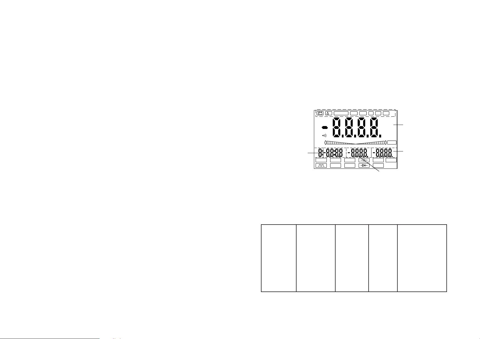
51
4.Descriptions des fonctions des éléments de
commande (introduction à l'aide des touches)
4.1 Description générale
Figure face avant, voir page en annexe
4.2 Affichage de base
Selon le modèle du multimètre numérique et la fonction de mesure, des
affichages différents peuvent être repris au display principal (S0) et aux
displays secondaires S1, S2 et S3. Le tableau ci-dessous en donne le détail
Fonction de S0 S1 S2 S3
mesure
ACV AC - volt Hz (<100kHz) ——- ——ACA AC - ampère Hz (<100kHz) ——- ——DCV DC - volt ——- ——- ——-
+
TRIG
±
REC
½
cly
ms
mV
%
dB
mV
KHz
¡C¡F
MAX MIN
%
MIN/MAX
TIME LMT PH REC RCLL
mVA%
AUTO
AC DC
TONE
Mk½Hz
¡C¡FnumF
HOLD
0-10-20-30 -30-20-10
Hz hfe
Logic
VOLT
½
mAATEMP
S0
S1
S2
S3
50
La valeur mesurée peut en être faussée.
• Evitez à tout prix, pour votre propre sécurité, de mouiller ou d'humidifier l'appareil ou ses câbles de mesure et adaptateurs.
• Utilisez uniquement pour les mesures, les câbles de mesure fournis
avec l'appareil de mesures ou les adaptateurs disponibles en options.
Ils sont les seuls à être agréés.
• Afin d'éviter tout risque d'électrocution, assurez-vous que pendant
l'opération de mesure vous n'entrez ni directement ni indirectement
en contact avec les zones de mesure ou avec les points sur lesquels s'effectuent les mesures.
• La tension entre une douille quelconque de l'appareil de mesure et la
terre ne doit pas dépasser 500 VDC ou VACrms.
• Si vous constatez que vous ne pouvez plus travailler sans risque, alors il
est recommandé de mettre l'appareil hors service et de s'assurer qu'il
ne sera pas remis en marche involontairement. Vous ne pouvez plus
travailler sans risque quand
- l'appareil présente des détériorations apparentes,
- l'appareil refuse de fonctionner et
- l'appareil est resté trop longtemps exposé à un environnement défa-
vorable ou
- après des conditions de transports difficiles.
• Ne branchez jamais l'appareil aussitôt après avoir quitté un local froid
pour rejoindre un local chaud. La condensation qui peut être provoquée peut détruire votre appareil sous certaines conditions. Laissez
l'appareil débranché en attendant qu'il s'acclimate à la température
ambiante de la pièce.
Page 27
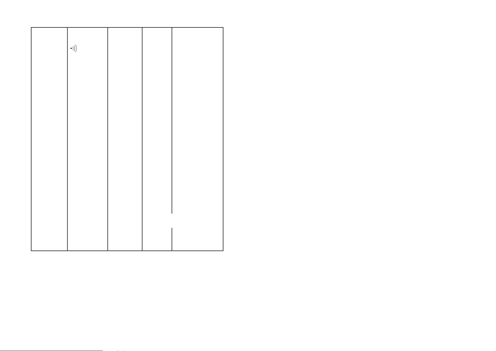
53
tion d'une valeur de mesure définie, la différence par rapport à celle-ci sera affichée. Par actionnement de la touche
"ENTER", la fonction est mise hors circuit.
„MIN/MAX“ Saisie de la valeur de mesure la plus élevée et de la valeur la
plus basse
„TIME“ horloge "interne"; l'afffichage s'opère jusqu'à l'heure
pleine en minutes et secondes, au-delà en heures et
minutes. Affichage max. 23:59 (23 heures, 59 minutes)
„LMT“ mesure comparative avec ajustage d'une limite inférieure et
supérieure (LMT; seulement VC 670)
„PH“ Peak Hold = mesure d'une valeur de pointe / affichage
(seulement VC 650 et VC 670)
„REC“ REC signifie Record (= saisir/mémoriser) une valeur mesurée;
il existe 10 mémoires. Le numéro de la mémoire correspondante figure tout à fait à gauche au display.
„RCLL“ Recall signifie appeler/interroger une valeur de mesure
mémorisée. Affectation des mémoires voir REC
autres positions
„HOLD“ signifie Data Hold; la valeur mesurée est retenue (par ex. à
des fins d'enregistrement) jusqu'à ce que la touche Hold
soit à nouveau actionnée ou que le DMM soit arrêté.
„AUTO“ apparaît au display, lorsque la sélection automatique de
mesure est activée
„TONE“ signal acoustique de reconnaissance de la valeur mesurée
(seulement VC 670)
„TRIG±“ touche de déclenchement pour la mesure d'une fréquence.
Déclenchement du flanc d'impulsion positif "+" ou négatif
"-" du signal de mesure.
52
4.3 Affichages au display respectivement symboles des modes
de fonctionnement
ligne supérieure de l'en-tête après actionnement de la touche "ENTER
MENU"
„Æ%“ signifie REL = = mesure valeur relative, possible pour ACV,
DCV, ohms/continuité, diode/capacité, mA/uA et A. En fonc-
Résistance ohm ——- ——- ——Passage ——- ——- ——Contrôle des mV ——- ——- ——-
diodes
hfe hfe ——- ——- ——-
Contrôle des nF, uF ——- ——- ——condensateurs
Hz Hz, kHz, MHz V (olt) ——- ms, 1/2 Durée de
la période
(0,01 - 99 msec)
TEMP °C / °F °F / °C ——- ———
TTL-Gen. Hz ——- ——- ——LOGIC Hi, Lo Hz V TTL/3V-CMOS/
5V-CMOS
D% Tolérance Valeur de Diff. en % ——-
référence
MIN/MAX momentanée Val. mesurée ——-
MIN MAX
PH = Peak Valeur mesurée ——- Valeur max. ——Hold momentanée („gelée“)
TIME (Horloge) - - - heures, minutes,
secondes <24h
Page 28

55
„ “ symbole pour le contrôle acoustique de continuité
tous les autres symboles, correspondent à différentes unités de mesure:
AC = grandeur alternative
DC = grandeur continue
mV = Millivolt (exposant -3)
V = volt (unité de la tension électrique)
A = ampère (unité de l'intensité du courant électrique)
Hz = hertz
kHz = kilohertz (exposant 3)
k½ = kiloohm (exposant 3)
M½ = megaohm (exposant 6)
pF = piko-farad (piko = exposant -12)
nF = nano-farad (nano = exposant -9)
uF = micro-farad (micro = exposant -6)
4.4 Affectation des touches et description des fonctions avec
introduction à l'aide des touches
4.4.1 Généralités
Avec les diverses touches sur l'appareil, tous les paramètres peuvent être
modifiés/ajustés. Selon le modèle d'appareil de mesures, les réglages suivants sont possibles: "TRIG" (tous les trois multimètres numériques),
éclairage „ „ (seulement sur VC 670), signal acoustique „ „ seulement sur VC 670), "RANGE" (sélection manuelle de la plage de mesure),
"AC/DC" avec „½ “, "HOLD", "POWER" (marche/arrêt), "ENTER
MENU" (touche d'actionnement), "" (touche de fonction de mesure par
54
„Logic“ affichage de la fonction logique, seulement sur VC 650 et
VC 670.
„HI“ signifie High-Level lors de la mesure du niveau logique
(niveau haut)
„LO“ signifie Low-Level lors de la mesure du niveau logique
(niveau bas)
„- - - -“ lors de la mesure du niveau logique, la valeur mesurée se
situe entre HI et LO
„PASS“ apparaît à la fonction LMT sur VC 670 et signifie que la
valeur mesurée se "situe" entre la limite supérieure et la
limite inférieure ajustées (=Limit)
„hfe“ affichage lors du test de transistors, mesure du paramètre
hfe (intensification)
„O.L“ signifie Overload = dépassement de la capacité. Valeur
mesurée trop grande ou limite de la plage de mesure
dépassée
„ „ symbole pour la sortie pour générateur de signaux (TTL) sur
VC 650 et VC 670
„ „ symbole pour échange de la batterie
„°C“ Unité de mesure degré Celsius lors de la mesure de la
température (adaptateur pour mesure de la température
en option) sur VC 650 et VC 670
„°F“ Unité de mesure degré Fahrenheit lors de la mesure de
température (habituelle en Angleterre) sur VC 650 et VC
670
„->I-“ symbole pour le test de diodes
„-I(-“ symbole pour la mesure de la capacité de condensateurs
bipolaires ou unipolaires
+
–
Page 29

57
Pour revenir sur la sélection de plage "AUTO", la touche "RANGE" devra
rester appuyée pendant env. 2 secondes.
4.4.4 „AC/DC/OHM “
Avec cette touche, vous passez de mesures de valeurs continues à mesures de valeurs alternatives (courant et tension) et de la mesure de résistances au contrôle de continuité acoustique et inversement.
4.4.5 HOLD
La touche"HOLD" doit être actionnée une fois, si par ex. vous procédez à
un enregistrement des valeurs et que vous désirez noter la valeur
momentanée mesurée avant que celle-ci se modifie à nouveau. Avec un
actionnement de la touche Hold, la valeur momentanée mesurée est
"gelée" respectivement gardée. La symbole "HOLD" apparaît au display
sur le côté droit. Dans cet "état", à côté de la touche Hold, seules les touches de fonctions de mesure autour de "ENTER" et l'interrupteur
"POWER" ont une influence sur le (les) réglage(s). Les autres touches se
trouvent sans fonction ( hors de service). Si vous désirez continuer la
mesure en cours, actionnez à nouveau la touche "HOLD" encore une
fois. La valeur de mesure momentanée est affichée.
4.4.6 POWER
Avec la touche "POWER" l'appareil de mesures est mis en service ou
arrêté. Si la valeur mesurée ne se modifie pas pendant env. 30 minutes,
l'appareil de mesures se met en "Stand by" (attente). A l'aide de cette
fonction Auto-Power-Off , on évite une consommation d'énergie trop
importante.
5.Ajustage des fonctions de mesure avec les
touches autour de "ENTER"
Les fonctions suivantes disposées dans un "cercle entier" autour de la
touche "ENTER" peuvent être sélectionnées:
a) au-dessus de "ENTER"
- Mesures de tensions alternatives jusqu'à max. 700 VACrms "V",
(True rms sur VC 670)
56
"ENTER"), "mA TEMP A" (touche de fonction de mesure à droite de
"ENTER"; TEMP seulement sur VC 650 et VC 670), "< >" (touche "auxi-
liaire" de réglage), "HzhfeLogic" „ (touche de fonction de mesure à
gauche de ENTER; „ „ et "Logic" seulement sur VC 650 et VC 670)
4.4.2 TRIG
a) Touche TRIG
Cette touche est nécessaire pour la mesure de fréquence afin de
basculer du déclenchement positif au déclenchement négatif.
Déclenchement positif "+" signifie, que le signal de mesure est
saisi au flanc ascendant. Déclenchement négatif "-" signifie, que
le signal de mesure est saisi au flanc descendant.
b) Eclairage (seulement sur VC 670)
Actionnez la touche pendant env. 2 secondes. L'éclairage de fond
pour une meilleure lisibilité en cas de conditions de luminosité
défavorables est allumé. Actionnez la touche à nouveau pendant
2 secondes. L'éclairage de fond est éteint.
Attention!
Ne laissez pas l'éclairage allumé trop longtemps. Il consomme beaucoup
d'énergie. Eteignez l'éclairage de fond dès qu'il n'est plus nécessité.
c) Signal TONE (seulement sur VC 670)
Cette fonction est activée par un seul actionnement de la touche
"TRIG" uniquement dans le cas de la mesure de la tension et de la
mesure de l'intensité du courant (mA et A). Selon l'importance du
signal de mesure ( y compris changement automatique de la plage) un signal acoustique d'une intensité plus ou moins forte retentit.
4.4.3 RANGE
Avec la touche "RANGE", on peut couper la sélection automatique de la
plage de mesure, c'est à dire, la plage de mesure choisie peut être sélectionnée manuellement. Lors de la mesure de la tension alternative, les
cinq plages 400mV-4V-40V-400V-700V peuvent être sélectionnées par
chaque action sur la touche "RANGE".
Page 30

59
5.1 Mesure d'une tension alternative
Pour la mesure de tensions alternatives jusqu'à max. 700 VACrms (=effectives), procédez de la manière suivante:
a) Mettez votre appareil de mesures en service. En position initiale, la
mesure de tensions alternatives est toujours réglée avec "AUTO"
(sélection automatique de la plage de mesure).
b) Reliez le câble de mesure noir à la douille "COM" de l'appareil de
mesures et le câble de mesure rouge avec la douille "V•½•Hz•Logic•-
>I-"
c) Pendant la mesure, en-dessous de la valeur affichée, un graphe à bar-
res est actif, un genre d'affichage analogique avec une plus grande
vitesse de mesure. Le graphe à barres remplit la fonction d'un indicateur de tendance.
d) Raccordez les broches de mesure sur l'objet à mesurer.
Attention!
En cas de dépassement de la plage de mesure (> 700 VACrms), un signal
acoustique se fait entendre (en intervalles). Veuillez ne jamais dépasser
les valeurs d'entrée maximales!
Remarques!
1. Pendant la mesure de la tension alternative, la fréquence de la tension alternative sera affichée au subdisplay ("petit" affichage) en bas à
droite, à côté de la valeur mesurée et du graphe à barres. Référezvous ici à la figure suivante.
AUTO
AC
VOLT
V
Hz
MAIN DISPLAY
BARGRAPH DISPLAY
SUB DISPLAY (S1)
(LCD)
0+10
58
- Mesures de tensions continues jusqu'à max. 1000 VDC "V",
- Mesures de résistances jusqu'à max. 40 M½ (VC 670 jusqu'à 400
Mohms) et contrôles de continuité (acoustique) jusqu'à max. 20
ohms
- Mesures de capacités jusqu'à max. 40 uF (VC 670: jusqu'à 400 uF) et
tests de diodes "-I(-" et "->I-".
b) à droite de „ENTER“
- Mesures de courants continus et alternatifs jusqu'à max. 400 mA
"mA", (True rms sur VC 670)
- Mesures de courants continus et alternatifs jusqu'à max. 20 A "A",
(True rms sur VC 670)
- Mesures de températures avec l'adaptateur en option uniquement
sur VC 650 et VC 670
c) à gauche de "ENTER"
- Mesures de fréquences jusqu'à max. 4 MHz "Hz" et de transistors
"hfe"
- Mesures logiques des niveaux jusqu'à max. 5 V (TTL, 3V, 5V)
„LOGIC“ (VC 650 et VC 670)
- Fonction comme générateur de signaux TTL jusqu'à max. 5 kHz
"SIG OUT" (VC 650 et VC 670)
Attention!
Respectez obligatoirement les valeurs d'entrée maximales tolérables!
Soyez prudent en ce qui concerne des manipulations sous des tensions
supérieures à 25 VACrms/DC: en cas de contact avec des conducteurs
électriques, il y a danger de mort par électrocution.
Avant de passer à d'autres fonctions de mesure, les câbles de mesure
sont à débrancher de l'objet à mesurer et de l'appareil de mesures.
Pour toutes vos mesures, utilisez exclusivement les câbles livrés avec
l'appareil de mesures respectivement les adaptateurs disponibles en
options. Contrôlez, avant chaque branchement, le bon état des éléments de branchement et des broches de mesure et vérifiez la qualité de
l'isolation. Les câbles de mesure, pas les adaptateurs, sont homologués
pour des tensions jusqu'à max. 1000 V. Votre multimètre, le VC 630 ou
VC 650 ou VC 670, est utilisable pour des tensions jusqu'à max.1000 VDC
respectivement 700 VACrms.
Page 31

61
Attention!
En cas de dépassement de la plage de mesure (> 1000 VDC), un signal
acoustique se fait entendre (en intervalles). Veuillez ne jamais dépasser
les valeurs d'entrée maximales!
Dès que le signe "-" apparaît devant la valeur mesurée, la tension
mesurée est négative (ou les câbles de mesure ont été intervertis).
Remarques!
1. Pendant la mesure d'une tension continue, il apparaît uniquement en
plus de la valeur mesurée, le graphe à barres. Aucun des subdisplays
est actif. Référez-vous ici à la figure suivante:
2. Fonctions spéciales ajustables
Les sous-fonctions suivantes sont, selon le type de multimètre, ajustables par la touche "ENTER MENU":
Mesure d'une valeur de référence "Æ%", saisie de la valeur
min./max., "TIME", l'enregistrement de la valeur mesurée "REC",
reprise (reproduction) de la valeur mesurée "RCLL", la fonction de
comparaison "LMT" (seulement sur VC 670), et la mesure de la valeur
de pointe "PH" (seulement sur VC 650 et VC 670). Ces sous-fonctions
sont décrites avec plus de précision au chapitre 5.12.
AUTO
VOLT
V
0 +10 +20 +30
60
2. Le VC 670 mesure la valeur effective réelle d'une grandeur alternative (True rms = vraie valeur effective). Ce mode de mesure est toujours judicieux lorsqu'il s'agit pour la tension, d'une tension sinusoïdale déformée, d'une tension d'ondulation ou d'une tension mixte ou d'une tension d'une fréquence plus élevée (par ex. d'un réseau
combinatoire).
3. Fonctions spéciales ajustables
Les sous-fonctions suivantes sont, selon le type de multimètre, ajustables par la touche "ENTER MENU":
Mesure d'une valeur de référence „Æ%“, saisie de la valeur
min./max., "TIME", l'enregistrement de la valeur mesurée "REC",
reprise (reproduction) de la valeur mesurée "RCLL", la fonction de
comparaison "LMT" (seulement sur VC 670), et la mesure de la valeur
de pointe "PH" (seulement sur VC 650 et VC 670). Ces sous-fonctions
sont décrites avec plus de précision au chapitre 5.12.
5.2 Mesure d'une tension continue
Pour la mesure de tensions continues jusqu'à max. 1000 VDC. Procédez
de la manière suivante:
a) Mettez votre appareil de mesures en service. En position initiale, la
mesure de tensions alternatives est toujours réglée avec "AUTO"
(sélection automatique de la plage de mesure). Actionnez maintenant une fois la touche "AC/DC". L'appareil passe maintenant sur
tension continue, reconnaissable au fait que le symbole "AC" sous
"AUTO disparaît.
b) Reliez le câble de mesure noir à la douille "COM" de l'appareil de
mesures et le câble de mesure rouge avec la douille
„V•½•Hz•Logic•->I-“
c) Pendant la mesure, en-dessous de la valeur affichée, un graphe à
barres est actif, un genre d'affichage analogique avec une plus
grande vitesse de mesure. Le graphe à barres remplit la fonction
d'un indicateur de tendance.
d) Raccordez les broches de mesure sur l'objet à mesurer.
Page 32

63
Si vous pratiquez une mesure de résistance, vérifiez bien que les points
à mesurer, qui vont être touchés par les pointes de mesure, ne sont pas
recouverts de saleté, d'huile, d'huile de soudure ou similaires. De telles
circonstances peuvent fausser la valeur mesurée.
Dès que "O.L" apparaît au display, vous avez dépassé la plage de mesure ou la section à mesurer est interrompue.
Ne mesurez jamais des condensateurs chargés, sinon si le condensateur
vient à se décharger, vous pouvez détruire votre appareil de mesures.
e) pour des mesures de continuité acoustiques/optiques jusqu'à max. 20
ohms, vous actionnerez une fois "AC/DC" avant la mesure. Ceci fera
passer l'appareil de mesures de la mesure „½“ à la mesure „•))“- .
Remarques!
1. Pendant la mesure de la résistance/contrôle de continuité, il apparaît
uniquement en plus de la valeur mesurée, le graphe à barres. Aucun
des subdisplays est actif. Référez-vous ici à la figure suivante:
2. Fonctions spéciales ajustables
Les sous-fonctions suivantes sont, selon le type de multimètre, ajustables par la touche "ENTER MENU":
Mesure d'une valeur de référence "Æ%", saisie de la valeur
min./max., "TIME", l'enregistrement de la valeur mesurée "REC",
reprise (reproduction) de la valeur mesurée "RCLL", la fonction de
comparaison "LMT" (seulement sur VC 670), et la mesure de la valeur
de pointe "PH" (seulement sur VC 650 et VC 670). Ces sous-fonctions
sont décrites avec plus de précision au chapitre 5.12.
AUTO
M½
½
0 +10 +20 +30
62
5.3 Mesure de la résistance et contrôle de continuité
Attention!
Assurez-vous que tous les branchements et éléments à mesurer ainsi
que tous les objets à mesurer sont absolument bien hors de tension.
Pour la mesure de résistances jusqu'à max. 40 Mohms (VC 670: jusqu'à
max. 400 Mohms) et contrôle de continuité (acoustique) jusqu'à max. 20
ohms, procédez de la manière suivante:
a) Mettez votre appareil de mesures en service. En position initiale, la
mesure de tensions alternatives est toujours réglée avec "AUTO"
(sélection automatique de la plage de mesure). Actionnez maintenant une fois la touche "Vo-I(-o½o->I-" . L'appareil passe maintenant
sur mesure de résistances, reconnaissable au fait que le symbole oméga apparaît au bord inférieur du display.
b) Reliez le câble de mesure noir à la douille "COM" de l'appareil de
mesures et le câble de mesure rouge avec la douille
„V••Hz•Logic•->I-“.
c) Pendant la mesure, en-dessous de la valeur affichée, un graphe à bar-
res est actif, un genre d'affichage analogique avec une plus grande
vitesse de mesure. Le graphe à barres remplit la fonction d'un indicateur de tendance.
d) Raccordez les broches de mesure avec l'objet à mesurer qui doit abso-
lument être hors tension.
Remarque(s)!
Si des résistances montées dans des circuits sont mesurées dans lesquelles se trouvent des transistors/diodes Si, la tension de contrôle de la plage 400 ohms est suffisante pour traverser ces semi-conducteurs. Les
mesures peuvent en être faussées.
La résistance des câbles de mesure est normalement très minime et sans
la moindre influence sur la mesure (environ 0,1 à 0,2 ohm).
Mais cette valeur même minime peut conduire à des inexactitudes dans
la mesure pour la catégorie des 400 ohms.
Page 33

65
vitesse de mesure. Le graphe à barres remplit la fonction d'un indicateur de tendance.
d) Raccordez les broches de mesure avec l'objet à mesurer d'une diode,
qui doit absolument être hors tension.
Remarque(s) pour la mesure des diodes!
Branchez les broches de mesure à l'élément semi-conducteur hors de
tension d'une diode ou d'un transistor. Il faudra veiller ici, que le câble
de mesure rouge doit être relié à l'anode et le câble de mesure noir à la
cathode. Maintenant, on mesure le sens de conduction. Dans le cas d'une jonction PN en ordre, il apparaît pour des secteurs de diodes Si une
valeur entre 0,45 et 0,75 VDC, pour des secteurs de diodes Ge une valeur
entre 0,2 et 0,4 VDC. Si à la place d'une valeur de tensions, il apparaît
"O.L" (pour débordement) le secteur des diodes est interrompu ou les
câbles de mesure sont intervertis. Si pour des transistors, on mesure une
tension supérieure à 1 V, il pourra s'agir de transistors avec des résistances incorporées.
Pour des DEL, on mesurera une tension de conduction d'env. 1,4 à 2,2
VDC. S'il s'agit d'une DEL Low-Current, le courant de mesure sera suffisant pour que celle-ci s'allume.
On mesurera le sens de non-conduction d'un secteur de diodes en reliant la cathode au câble de mesure rouge et l'anode au câble de mesure
noir. Si une tension s'affiche la diode est défectueuse. Si par contre
"O.L" apparaît, le secteur de diodes est de valeur ohmique élevée (en
ordre).
Remarques générales!
1. Pendant la mesure de la capacité/contrôle des diodes, il apparaît uniquement en plus de la valeur mesurée, le graphe à barres. Aucun des
sub-displays est actif. Référez-vous ici à la figure suivante:
64
5.4 Mesure de diodes et capacité „->I- -I(-“
Attention!
Déchargez chaque condensateur avant de le relier à l'appareil de mesures. Si des courts-circuits de condensateurs se produisent, des décharges
d'énergie puissantes peuvent survenir.
Attention dans des locaux où se présentent ou peuvent se présenter des
poussières, des gaz inflammables, des vapeurs ou des liquides
inflammables. ==> Danger d'explosion!
Ne touchez jamais les connections de condensateurs sous des tensions
supérieures à 35 VDC ou 25 VAC.
Attention: danger de mort!
Ne procédez pas à des mesures sur des condensateurs qui se trouvent
montés dans des circuits/dans des éléments de circuits.
Pour la mesure de diodes et de secteurs semi-conducteurs respectivement de condensateurs jusqu'à max. 40 uF (VC 670: jusqu'à max. 400 uF).
Procédez de la manière suivante:
a) Mettez votre appareil de mesures en service. En position initiale, la
mesure de tensions alternatives est toujours réglée avec "AUTO"
(sélection automatique de la plage de mesure). Actionnez maintenant deux fois la touche „V•-I(-•½•->I-“. L'appareil passe maintenant
sur mesure de capacités, reconnaissable au fait que le symbole condensateur apparaît au bord inférieur du display.
Si vous actionnez la touche „V•-I(-•½•->I-“ une nouvelle fois (de la
position initiale: trois fois), vous parvenez au contrôle des diodes,
reconnaissable au fait que le symbole diode apparaît au bord
inférieur du display.
b) Reliez pour le contrôle des diodes, le câble de mesure noir à la douille
"COM" de l'appareil de mesures et le câble de mesure rouge avec la
douille „V•½•Hz•Logic•->I-“. Pour la mesure de la capacité, seul le
socle de mesure à droite à côté de la touche „mA•TEMP•A“ est à utiliser (TEMP seulement sur VC 650 et VC 670).
c) Pendant la mesure, en-dessous de la valeur affichée, un graphe à bar-
res est actif, un genre d'affichage analogique avec une plus grande
Page 34

67
5.5 Mesure de courant continu et de courant alternatif (mA),
DCmA et ACmA
Pour la mesure de courants continus et alternatifs de basses intensités
jusqu'à max. 400 mAACrms (=effectives) ou mADC. Procédez de la
manière suivante:
a) Mettez votre appareil de mesures en service. En position initiale, la
mesure de tensions alternatives est toujours réglée avec "AUTO"
(sélection automatique de la plage de mesure). Actionnez maintenant une fois la touche „mA•TEMP•A“. L'appareil passe maintenant
sur mesure de courants alternatifs mA, reconnaissable au fait que le
symbole "AC" gauche de la valeur mesurée au display. Pour la mesure de courants continus jusqu'à max. 400 mA, actionnez une fois la
touche "AC/DC".
b) Reliez le câble de mesure noir à la douille "COM" de l'appareil de
mesures et le câble de mesure rouge avec la douille "mA" sur VC 630
respectivement „mA•TEMP• “ sur VC 650 et VC 670.
c) Pendant la mesure, en-dessous de la valeur affichée, un graphe à bar-
res est actif, un genre d'affichage analogique avec une grande vitesse
de mesure. Le graphe à barres remplit la fonction d'un indicateur de
tendance.
d) Raccordez les câbles de mesure en série à l'objet à mesurer (voir figu-
re ci-dessous).
Attention!
Si lors de la mesure du courant continu le signe "-" apparaît devant la
valeur mesurée, le courant mesuré est négatif (ou les câbles ont été
intervertis).
A
~
Fusible
Source de
courant
Appareil
de mesures
Consommateur
66
2. Fonctions spéciales ajustables
Les sous-fonctions suivantes sont, selon le type de multimètre, ajustables par la touche "ENTER MENU":
Mesure d'une valeur de référence „Æ%“, saisie de la valeur
min./max., "TIME", l'enregistrement de la valeur mesurée "REC",
reprise (reproduction) de la valeur mesurée "RCLL", la fonction de
comparaison "LMT" (seulement sur VC 670), et la mesure de la valeur
de pointe "PH" (seulement sur VC 650 et VC 670). Ces sous-fonctions
sont décrites avec plus de précision au chapitre 5.12.
AUTO
mV
AUTO
µF
0 +10 +20
Page 35

69
5.6 Mesure de courant continu et de courant alternatif 20 A
Pour la mesure de courants continus et alternatifs d'une intensité jusqu'à
max. 20 AACrms (= effectives) ou ADC. Procédez de la manière suivante:
a) Mettez votre appareil de mesures en service. En position initiale, la
mesure de tensions alternatives est toujours réglée avec "AUTO"
(sélection automatique de la plage de mesure). Actionnez maintenant deux fois la touche „mA•TEMP•A“. L'appareil passe maintenant
sur mesure de courants alternatifs A, reconnaissable au fait que le
symbole "AC" gauche de la valeur mesurée au display. Pour la mesure de courants continus jusqu'à max. 20 A, actionnez deux fois la touche "AC/DC".
b) Reliez le câble de mesure noir à la douille "COM" de l'appareil de
mesures et le câble de mesure rouge avec la douille "20 A".
c) Pendant la mesure, en-dessous de la valeur affichée, un graphe à bar-
res est actif, un genre d'affichage analogique avec une plus grande
vitesse de mesure. Le graphe à barres remplit la fonction d'un indicateur de tendance.
d) Raccordez les câbles de mesure en série à l'objet à mesurer (voir figu-
re ci-dessous).
La touche "RANGE" (sélection manuelle de la plage de mesure) est "sans
fonction" lors de la mesure de courant "A".
Attention!
Notez que dès qu'apparaît un signe “-” devant la valeur mesurée, dans le
cas de mesure de tensions de courant continu, la valeur mesurée porte
sur une tension négative (ou vos câbles de mesure ont été intervertis). Ne
A
~
Fusible
Source de
courant
Appareil
de mesures
Consommateur
68
Ne mesurez pas des courants dans des circuits avec des tensions
supérieures à 250 VDC ou VACrms peuvent se présenter, il y a danger de
mort. Mesurez en aucun cas des courants supérieurs à 400 mA. Mesurez
des courants inférieurs ou égaux à 400 mA uniquement dans des circuits
eux-mêmes protégés avec 400 mA à action instantanée.
Remarques!
1. Pendant la mesure du courant alternatif, la fréquence du courant
alternatif sera affiché au subdisplay en bas à droite ("petit" affichage) à côté de la valeur mesurée et du graphe à barres. Référez vous
à la figure suivante.
2. Le VC 670 mesure la valeur effective réelle d'une grandeur alternati-
ve (True rms = vraie valeur effective). Ce mode de mesure est toujours judicieux lorsqu'il s'agit pour le signal de mesure, d'un signal
sinusoïdal déformé, d'un signal d'ondulation ou d'un signal mixte
ou d'un signal d'une fréquence plus élevée (par ex. d'un réseau combinatoire).
3. Fonctions spéciales ajustables
Les sous-fonctions suivantes sont, selon le type de multimètre, ajustables par la touche "ENTER MENU":
BMesure d'une valeur de référence "Æ%", saisie de la valeur
min./max., "TIME", l'enregistrement de la valeur mesurée "REC",
reprise (reproduction) de la valeur mesurée "RCLL", la fonction de
comparaison "LMT" (seulement sur VC 670), et la mesure de la valeur
de pointe "PH" (seulement sur VC 650 et VC 670). Ces sous-fonctions
sont décrites avec plus de précision au chapitre 5.12.
AUTO
AC
mA
mA
Hz
0 +10 +20
Page 36

71
reprise (reproduction) de la valeur mesurée "RCLL", la fonction de
comparaison "LMT" (seulement sur VC 670), et la mesure de la
valeur de pointe "PH" (seulement sur VC 650 et VC 670). Ces sousfonctions sont décrites avec plus de précision au chapitre 5.12.
5.7 Mesure de la température (uniquement sur VC 650 et VC 670)
La plage de mesure de la température du multimètre numérique s'étend
de - 40°C à +1000°C. La mesure de la température s'effectue exclusivement avec des capteurs thermiques du type k. Il faudra tenir compte, que
"en-dehors" de la plage de température de +18°C à + 28°C (= plage de
précision de mesure garantie) uniquement l'élément thermique devra
être soumis à la température à mesurer. De plus le kit de mesure de la
température est disponible en option, il ne fait pas partie de l'ensemble
de la livraison. Si un kit capteur n'est pas branché à l'appareil de mesures, la température ambiante de la pièce est automatiquement mesurée
et affichée (en °C et °F).
Pour la mesure de la température. Procédez de la manière suivante:
a) Mettez votre appareil de mesures en service. En position initiale, la
mesure de tensions alternatives est toujours réglée avec "AUTO"
(sélection automatique de la plage de mesure). Actionnez maintenant trois fois la touche "mA•TEMP•A" . L'appareil passe maintenant
sur mesure de la température, reconnaissable au fait que le symbole "
TEMP" apparaît en bas à droite au display et par l'affichage de la
température en degrés C respectivement en degrés F au subdisplay.
b) Enfichez la fiche de l'élément thermique en respectant la polarité
(contacts à couteau mince et large) dans l'adaptateur pour la mesure
de la température et celui-ci en respectant également la bonne polarité ("+" et "-" ) dans la douille "COM" (="-") et dans la douille
„mA•TEMP• „ (=“+“).
c) Pendant la mesure, en-dessous de la valeur affichée, un graphe à bar-
res est actif, un genre d'affichage analogique avec une plus grande
vitesse de mesure. Le graphe à barres remplit la fonction d'un indicateur de tendance.
d) Reliez les pointes des capteurs de l'élément thermique à l'objet à
mesurer, qui doit être exempt de tension. Maintenez les capteurs de
70
mesurez jamais du courant d'un circuit électrique avec des tensions
supérieures à 250 VDC ou VACrms : sinon vous risquez d'endommager le
multimètre et vous serez même en danger de mort. N'effectuez vos
mesures que sur des circuits protégés par des fusibles à 20 A qui ne laissent pas passer des charges supérieures à 4000 VA. Des mesures de courant électrique de 20 A ne doivent pas avoir un période supérieur à 30s
et ne doivent être effectuées qu'en respectant des intervalles de 15 minu tes entre chaque mesure (temps de refroidissement de la dérivation).
Remarques!
1.Pendant la mesure du courant alternatif, la fréquence du courant
alternatif sera affiché au subdisplay en bas à droite ("petit" affichage)
à côté de la valeur mesurée et du graphe à barres. Référez vous à la
figure suivante.
2. Le VC 670 mesure la valeur effective réelle d'une grandeur alternative (True rms = vraie valeur effective). Ce mode de mesure est toujours judicieux lorsqu'il s'agit pour le signal de mesure, d'un signal
sinusoïdal déformé, d'un signal d'ondulation ou d'un signal mixte ou
d'un signal d'une fréquence plus élevée (par ex. d'un réseau combinatoire).
3. Fonctions spéciales ajustables
Les sous-fonctions suivantes, sont selon le type de multimètre ajustables par la touche "ENTER MENU":
#Mesure d'une valeur de référence „Æ%“, saisie de la valeur
min./max., "TIME", l'enregistrement de la valeur mesurée "REC",
AUTO
AC
A
A
Hz
0 +10 +20
Page 37

73
(sélection automatique de la plage de mesure). Actionnez maintenant une fois la touche „Hz•hfe• •Logic“. L'appareil passe maintenant sur mesure de la fréquence, reconnaissable au fait que le symbole "Hz" apparaît en bas à gauche au display et par l'affichage de la
durée de la période en ms au subdisplay gauche et de la tension en
V au subdisplay à droite. De plus, à gauche en-dessous de la valeur
mesurée apparaît le symbole TRIG avec "+" ou "-".
b) Reliez le câble de mesure noir avec la douille "COM"
de l'appareil de mesures et le câble de mesure rouge avec la douille
„V•½•Hz•Logic•->I-“.
c) Pendant la mesure, en-dessous de la valeur affichée, un graphe à
barres est actif, un genre d'affichage analogique avec une grande
vitesse de mesure. Le graphe à barres remplit la fonction d'un indicateur de tendance.
d) Reliez le câble de mesure noir (pointe d'essai) à la masse de la con-
nexion ou du générateur de signaux et le câble de mesure rouge
(pointe d'essai) au signal à mesurer.
Attention!
Tenez compte absolument des valeurs maximales d'entrée! Ne branchez
pas des tensions supérieures à max. 250 VDC respectivement VACrms
(rms= eff). En cas de tensions supérieures à 25 VAC respectivement 35
VDC, il y a danger de mort en cas de contact.
Ne commutez pas pendant la mesure sur une autre fonction de mesure
respectivement sur une autre plage de mesure. Lors de la commutation
sous tension (riche en énergie), il peut se produire une étincelle à rupture, qui irrémédiablement pourra détruire les pistes conductives à
l'intérieur de l'appareil de mesures. De plus vous pouvez être mis en
danger par la destruction de l'appareil de mesures. Une mesure de la fréquence n'est pas possible pour des tensions inférieures à env. 50 mVrms
(mesurées à 1 KHz).
Remarques!
1. Pendant la mesure de la fréquence, est affichée, à côté de la valeur
mesurée et du graphe à barres, au subdisplay en bas à droite ("petit"
72
température sur ou dans l'objet à mesurer jusqu'à ce que l'affichage
au multimètre numérique se soit stabilisé (env. 30 secondes).
Attention!
Ne branchez pas de tension. L'appareil pourrait s'en trouver détérioré.
Remarques!
1. Pendant la mesure de la température, celle-ci est affichée, à côté de
la valeur mesurée et du graphe à barres, au subdisplay en bas à droite ("petit" affichage) en "°F". Référez-vous à la figure suivante.
2. Fonctions spéciales ajustables
Les sous-fonctions suivantes sont, selon le type de multimètre, ajustables par la touche "ENTER MENU":
Mesure d'une valeur de référence "Æ%", saisie de la valeur
min./max., "TIME", l'enregistrement de la valeur mesurée "REC",
reprise (reproduction) de la valeur mesurée "RCLL", la fonction de
comparaison "LMT" (seulement sur VC 670), et la mesure de la
valeur de pointe "PH" (seulement sur VC 650 et VC 670). Ces sousfonctions sont décrites avec plus de précision au chapitre 5.12.
5.8 Mesure de la fréquence
a) Mettez votre appareil de mesures en service. En position initiale, la
mesure de tensions alternatives est toujours réglée avec "AUTO"
AUTO
¡C
¡F
TEMP
0 +10 +20
Page 38

75
b) Pendant la mesure, en-dessous de la valeur affichée, un graphe à bar-
res est actif, un genre d'affichage analogique avec une plus grande
vitesse de mesure. Le graphe à barres remplit la fonction d'un indicateur de tendance..
c) Enfichez le transistor à contrôler dans le socle de mesure. Tenez
compte du cycle de branchement (par ex. C-B-E) de l'objet à mesurer
(à reprendre au tableau/liste de comparaison des transistors).
Tenir compte de ce qui suit:
- Certains transistors contiennent des résistances d'émetteur de base,
ceci peut fausser la mesure.
- La valeur hfe mesurée n'est pas absolument exacte. Elle indique
seulement si le transistor travaille ou ne travaille pas. L'intensification
réelle d'un transistor dépend de son courant de travail. Ce multimètre peut livrer un courant de base allant jusqu'à 10uA, pour une Uce
de 2,8 V. Le courant collecteur circulant lors de la mesure est saisi et la
valeur hFE en est déduite/évaluée.
- Des transistors incorporés à un circuit ne peuvent pas être mesurés.
- Avec ce multimètre, vous ne pouvez pas mesurer les valeurs hfe de
TEC ou d'autres transistors unipolaires.
- Si les "jambes" de branchement de l'objet à mesurer ne peuvent pas
être enfichées sur le socle (trop grosses), ne forcez pas, vous pourriez
endommager le socle.
- La mesure hfe réagit aux variations de la température. Dès que vous
touchez le transistor et que vous l'enfichez dans le socle, vous le
réchauffez avec vos doigts, la valeur peut se modifier. S'il en résulte
un affichage instable, retirez le transistor et laissez le reprendre la
température ambiante de la pièce.
Remarques!
1. Pendant le contrôle du transistor seul le graphe à barres est affiché à
côté de la valeur mesurée. Les subdisplays ne sont pas actifs.
74
affichage) l'amplitude de la tension mesurée en VACrms; de plus au
subdisplay à gauche la 1/2 de la durée de la période (1/2 de la valeur
réciproque de la fréquence) du signal de mesure (jusqu'à 100kHz).
Référez-vous à la figure suivante.
2. Fonctions spéciales ajustables
Les sous-fonctions suivantes sont, selon le type de multimètre, ajustables par la touche "ENTER MENU":
Mesure d'une valeur de référence "Æ%", saisie de la valeur
min./max., "TIME", l'enregistrement de la valeur mesurée "REC",
reprise (reproduction) de la valeur mesurée "RCLL", la fonction de
comparaison "LMT" (seulement sur VC 670), et la mesure de la
valeur de pointe "PH" (seulement sur VC 650 et VC 670). Ces sousfonctions sont décrites avec plus de précision au chapitre 5.12.
5.9 Contrôle de transistor
Attention!
Le socle des transistors n'est pas protégé contre une surintensité.
Pour la mesure du paramètre hFE (intensification) d'un transistor, procédez de la manière suivante:
a) Mettez votre appareil de mesures en service. En position initiale, la
mesure de tensions alternatives est toujours réglée avec "AUTO"
(sélection automatique de la plage de mesure). Actionnez maintenant trois fois la touche "Hzohfeo oLogic". L'appareil passe maintenant sur contrôle de transistor, reconnaissable au fait que le symbole
"hfe" apparaît en bas à gauche au display.
AUTO
Hz
0 +10 +20
ms
mV
Page 39

77
c) Pendant la mesure, en-dessous de la valeur affichée, un graphe à bar-
res est actif, un genre d'affichage analogique avec une plus grande
vitesse de mesure. Le graphe à barres remplit la fonction d'un indicateur de tendance.
d) Reliez maintenant l'autre extrémité du câble de mesure noir (pointe
de mesure) avec la "masse" du circuit numérique (normalement) = "-".
e) Maintenant que le câble de mesure noir est relié à la masse, vous tou-
chez avec la pointe de mesure rouge les points correspondants à
tester.
5.11 Utilisation comme générateur de signaux (pas sur VC 630)
Dans le multimètre numérique se trouve une sorte de "générateur de
fonction", qui livre à la sortie des douilles de mesure centrales une fréquence variable limitée de 1 Hz à 5 (5,041) kHz avec une tension fixe
(=amplitude) de 5 V.
Pour émettre un niveau TTL d'une fréquence variable limitée, procédez
de la manière suivante:
a) Mettez votre appareil de mesures en service. En position initiale, la
mesure de tensions alternatives est toujours réglée avec "AUTO"
(sélection automatique de la plage de mesure). Actionnez mainten-
ant deux fois la touche „Hz•hfe• •Logic“. L'appareil passe maintenant sur la sortie du générateur de signaux, reconnaissable au fait
que le symbole „ “ apparaît tout en bas à gauche au display.
b) Reliez le câble de mesure noir à la douille "COM" sur l'appareil de
mesure et le câble de mesure rouge à la douille „mA•TEMP• “
sur VC 650 et VC 670.
c) Sous l'affichage de la fréquence de sortie, le graphe à barres est visi-
ble, mais il n'a pas ici la fonction d'un indicateur de tendance.
d) Reliez les pointes de mesure à l'objet à mesurer et suivez si nécessai-
re, les manipulations suivantes à effectuer avec les touches pour régler la fréquence de sortie:
Avec chaque action sur la touche fléchée "<" (sous "Enter"), vous modifiez la fréquence de sortie d'un pas vers le bas. Avec chaque action sur la
76
2. Fonctions spéciales ajustables
Les sous-fonctions suivantes sont, selon le type de multimètre,
ajustables par la touche "ENTER MENU":
Mesure d'une valeur de référence "Æ%", saisie de la valeur
min./max., "TIME", l'enregistrement de la valeur mesurée "REC",
reprise (reproduction) de la valeur mesurée "RCLL", la fonction de
comparaison "LMT" (seulement sur VC 670), et la mesure de la valeur
de pointe "PH" (seulement sur VC 650 et VC 670). Ces sous-fonctions
sont décrites avec plus de précision au chapitre 5.12.
5.10 Test logique (pas sur VC 630)
Cette fonction de mesure sert à déterminer les niveaux logiques dans des
circuits numériques (27-TTL-, 3-V- ou 5-V-logique ou similaires). Cette
fonction logique permet de constater les "états" suivants:
- le point testé présente un niveau High supérieur à 70 % de Vcc sur
alors "Hi" apparaît à l'affichage.
- le point testé présente un niveau Low inférieur à 30 % de Vcc, alors
"Lo" apparaît à l'affichage.
- le point testé présente un niveau entre 30% et 70% de la Vcc, alors
"----------" apparaît à l'affichage
Pour constater le niveau logique respectivement pour ajuster les plages
de niveaux. Procédez de la manière suivante:
a) Mettez votre appareil de mesures en service. En position initiale, la
mesure de tensions alternatives est toujours réglée avec "AUTO"
(sélection automatique de la plage de mesure). Actionnez mainten-
ant quatre fois la touche „Hz•hfe• •Logic“. L'appareil passe
maintenant sur test logique, reconnaissable au fait que le symbole
"Logic" apparaît tout en bas au display et par l'affichage de la tension en V au subdisplay du milieu et de la fréquence en kHz au subdisplay de droite. De plus à gauche de l'affichage de la tension pour
niveau TTL, il apparaît un "t", pour "CMOS 3V" => "3C" et pour
"CMOS 5V" => "5C".
b) Reliez le câble de mesure noir avec la douille "COM" de l'appareil de
mesures et le câble de mesures rouge avec la douille „V• ½•Hz•Logic•-
>I-“.
Page 40

79
des résistances de basses impédances, sans avoir à soustraire à chaque mesure, la résistance du câble de mesure de la valeur mesurée.
La mesure avec une valeur de référence est possible pour la mesure
de la tension, pour la mesure du courant, la mesure de la résistance,
la mesure de la capacité et de la température (TEMP seulement sur
VC 650 et VC 670). Du fait, que lors de la mesure avec une valeur de
référence, "AUTO"-Range est désactivé, vous devez avant cette
fonction spéciale sélectionner (manuellement) la plage de mesure
choisie.
Pour ajuster la valeur de référence. Procédez de la manière suivante:
Réglez la plage de mesure souhaitée (à l'aide de la touche RANGE).
Mesurez la valeur de référence nécessaire, par ex. une tension continue de 12 VDC. Actionnez une fois la touche "ENTER MENU". Le
menu apparaît à l'en-tête. Actionnez encore une fois la touche
(temps imparti 6 secondes) "ENTER MENU". La première fonction
spéciale "Æ %", est ajustée. Votre valeur de référence "12 VDC"
apparaît au petit display de droite (subdisplay).
5.13 Sous-fonction "MIN/MAX-saisie de valeurs"
Si vous désirez saisir la valeur la plus élevée (=MAX) et la valeur la plus
basse (=MIN) d'une grandeur de mesure variant en permanence,
actionnez la touche "ENTER MENU" pendant la mesure. Le menu à l'entête devient visible. Le premier symbole ( pour la valeur de référence) clignote. Avec la touche "< >" vous pouvez "passer" d'un symbole à l'autre.
Actionnez la touche aussi longtemps jusqu'à ce que le symbole
"MIN/MAX" clignote. Ensuite actionnez à nouveau la touche "ENTER
MENU". Le clignotement s'arrête et la saisie des valeurs MIN/MAX
démarre.
Clairement et avant tout simultanément, apparaissent sur toute la surface du display , la valeur actuelle mesurée, la valeur maximale (subdisplay
central) et la valeur minimale au subdisplay de droite
Pour quitter la fonction MIN / MAX, actionnez une fois brièvement la
touche ENTER MENU ou la touche AC/DC ou une des touches des fonctions de mesure autour de la touche ENTER MENU => le display actuel
apparaît.
78
touche fléchée ">", vous modifiez la fréquence de sortie d'un pas vers le
haut.
Attention!
Ne court-circuitez pas la sortie de l'appareil de mesures ("sortie du
générateur"), l'appareil de mesures pourrait en être détruit.
Ne branchez pas des tensions, l'appareil pourrait également en être
endommagé/détruit.
Remarque!
Fonctions spéciales ajustables
Les sous-fonctions suivantes sont, selon le type de multimètre, ajustables par la touche "ENTER MENU": "TIME". Ces sous-fonctions sont décrites avec plus de précision au chapitre 5.12.
5.12 Généralités et sous fonctions " Mesure d'une valeur de
référence"
a) Généralités
Aux chapitres suivants seront décrites les fonctions spéciales, que
vous trouverez en en-tête à l'affichage LCD après avoir actionné la
touche "ENTER MENU". Selon le type d'appareil, il apparaîtra plus
ou moins de symboles pour les fonctions. Si vous ne choisissez pas
de fonction spéciale, la sélection disparaît d'elle-même au bout
d'env. 6 secondes.
b) Mesure avec une valeur de référence „Æ%“
La mesure avec une valeur de référence représentée par le signe
delta et le signe indiquant le pourcentage, permet des mesures se
rapportant à une valeur préalablement ajustée. Cette valeur ajustée apparaît non modifiée au subdisplay de droite. A côté, à gauche, au subdisplay central, la différence est indiquée en pourcentage, au "display principal", apparaît la valeur actuelle mesurée. Cette fonction se prête particulièrement à la mesure des résistances.
L'affichage peut être mis sur "0000", c.à.d. vous pouvez mesurer
Page 41

81
gnote. Avec la touche "< >" vous pouvez "passer" d'un symbole à l'autre. Actionnez la touche aussi longtemps jusqu'à ce que le symbole "LMT"
clignote. Confirmez la sélection avec la touche "ENTER". Maintenant trois subdisplays apparaissent, au subdisplay de gauche est affiché la valeur
de mesure actuelle. Au subdisplay central, on introduira la valeur limite
supérieure et au subdisplay de droite, on introduira la valeur limite
inférieure. Le subdisplay de droite clignote. Actionnez maintenant la
touche "< >" , en appuyant sur le bord de droite (+) ou de gauche (-) on
pourra introduire la valeur limite inférieure. Confirmez avec la touche
"ENTER". Le subdisplay central clignote. Procédez de la même manière
pour introduire la valeur limite supérieure. Actionnez une fois la touche
"ENTER" pour confirmer . Selon la grandeur de la valeur mesurée, "P ASS"
sera affiché, si la valeur mesurée se situe entre la valeur limite supérieure et la valeur limite inférieure. "LO" sera affiché, si la valeur mesurée est
inférieure à la valeur limite inférieure introduite. "HI" sera affiché, si la
valeur mesurée est supérieure à la valeur limite supérieure introduite.
5.16 Sous-fonction "Mesure de la valeur de pointe Peak-Hold
"PH" (pas sur VC 630)
Avec la fonction Peak-Hold, on saisit la plus grande valeur mesurée et
celle-ci est affichée. Actionnez la touche "ENTER MENU". Le menu à l'entête devient visible. Le premier symbole ( pour la valeur de référence) clignote. Avec la touche "< >" vous pouvez "passer" d'un symbole à l'autre.
Actionnez la touche aussi longtemps jusqu'à ce que le symbole "PH" clignote. Confirmez la sélection avec la touche "ENTER".
Au subdisplay central, apparaît la valeur de pointe saisie pendant une
durée de millisecondes (ms). Au display principal apparaît la valeur actuelle mesurée. Pour quitter la fonction "PH", actionnez une fois brièvement la touche ENTER MENU ou la touche AC/DC ou une des touches des
fonctions de mesure autour de la touche ENTER MENU => le display actuel apparaît.
5.17Sous-fonction "Enregistrement de la valeur mesurée REC" et
"Reprise de la valeur mesurée RCLL"
Avec la sous-fonction enregistrement "REC" et reprise "RCLL", on pourra
enregistrer et reprendre jusqu'à 10 valeurs mesurées. Les valeurs restent
conservées même après mise hors service de l'appareil de mesures.
80
5.14 Sous fonction "TIME" (saisie du temps)
Avec la fonction "TIME", on peut démarrer une horloge pendant la
mesure, celle-ci enregistrera le temps depuis le départ de la mesure. La
mémoire d'enregistrement pour le temps va jusqu'à 24 heures. Pour la
première heure, celle-ci sera indiquée en minutes et secondes, ensuite en
heures et minutes.
Réglage de l'horloge. Procédez de la manière suivante:
Actionnez la touche "ENTER MENU" avant ou pendant la mesure. Le
menu à l'en-tête devient visible. Le premier symbole ( pour la valeur de
référence) clignote. Avec la touche "< >" vous pouvez "passer" d'un symbole à l'autre. Actionnez la touche aussi longtemps jusqu'à ce que le
symbole "TIME" clignote. Confirmez la sélection avec la touche
"ENTER".
Au subdisplay de gauche apparaît l'horloge. Avec la touche "< >" , on
pourra démarrer ou arrêter l'horloge ou la remettre à zéro (Reset). Une
action sur la flèche de gauche (côté gauche de la touche) signifie: arrêter
ou démarrer l'horloge. Une action sur la flèche de droite (côté droit de la
touche) signifie: remise de l'horloge à "zéro". Pour quitter la fonction
"TIME", actionnez une fois brièvement la touche ENTER MENU ou la touche AC/DC ou une des touches des fonctions de mesure autour de la touche ENTER MENU => le display actuel apparaît.
5.15 Sous-fonction "Mesure avec valeur de comparaison LMT"
seulement sur VC 670
Avec la fonction LMT = Limit, des mesures comparatives sont possibles.
Dans cette sous-fonction, vous pouvez procéder à une comparaison haut/
bas, en comparant la valeur de référence la plus élevée en mémoire et la
valeur de référence la plus basse en mémoire avec la valeur de la mesure
actuelle. Pour quitter la fonction "LMT", actionnez une fois brièvement
la touche ENTER MENU ou la touche AC/DC ou une des touches des fonctions de mesure autour de la touche ENTER MENU => le display actuel
apparaît.
Introduction de la valeur limite (Limit = valeur limite). Procédez de la
manière suivante:
Réglez d'abord la plage de mesure souhaitée manuellement à l'aide de
la touche RANGE. Actionnez la touche "ENTER MENU". Le menu à l'entête devient visible. Le premier symbole ( pour la valeur de référence) cli-
Page 42

83
2. la liaison étant faite, mettez votre appareil de mesures en service
par action sur la touche "POWER".
3. actionnez la touche "HOLD" aussi longtemps (env. pendant 3 s ),
jusqu'à ce que le symbole circulaire avec un "2" apparaissent en bas
à droite sous le display principal.
4. Mettez le PC en service ("Ordinateur").
5. Utilisation du logiciel Windows (disponible en option):
Attention!
Les pas suivants au programme présupposent des connaissances de
base de MS-Windows. En cas de doute, consultez le manuel Windows
sur l'application de WINDOWS.
L'utilisation de ce logiciel suppose, Windows - version '95 et un moniteur (display) VGA.
a) Mettez votre computer en service et activez Windows.
b) Introduisez la disquette 3,5" dans le lecteur correspondant
(a ou b).
c) Cliquez sur la fenêtre "START" et cliquez avec la souris sur "EXE-
CUTER".
Il apparaît une fenêtre de menu avec une ligne d'instructions.
d) Lorsque que le "Curseur" clignote, introduisez ce qui suit:
a:\setup et actionnez la touche Enter pour le lecteur a, si la disquette se trouve dans le lecteur a
b:\setup et actionnez la touche Enter pour le lecteur b, si la dis-
quette se trouve dans le lecteur b
e) Suivez les instructions à l'écran pour terminer l'installation.
f ) Pour démarrer le programme, "cliquez" avec la touche gauche
de la souris (brièvement deux fois) sur le "Multimètre" appa-
raissant au programme Start et suivez ensuite les instructions à
l'écran.
Tenez également compte du fichier "README" de votre dis-
quette pour les indications de fonctionnement
82
Pour l'enregistrement, procédez de la manière suivante:
Actionnez la touche "ENTER MENU". Le menu à l'en-tête devient visible.
Le premier symbole ( pour la valeur de référence) clignote. Avec la touche "< >" vous pouvez "passer" d'un symbole à l'autre. Actionnez la touche aussi longtemps jusqu'à ce que le symbole "REC" clignote. Confirmez
la sélection avec la touche "ENTER". L'appareil de mesures est maintenant prêt à enregistrer. Actionnez maintenant la touche "< >" , en
appuyant sur le bord de droite (">"), on définira le numéro de la mémoire ( de 0 à 9). En appuyant sur le bord gauche de la touche, la valeur
mesurée sera enregistrée; toute action suivante sur le bord gauche de la
touche entraînera dans la même mémoire un recouvrement de la
donnée précédente. Le numéro de la mémoire correspondante est
affiché tout à fait à gauche du subdisplay.
Reprise de la valeur mémorisée. Procédez de la manière suivante:
Actionnez la touche "ENTER MENU". Le menu à l'en-tête devient visible.
Le premier symbole ( pour la valeur de référence) clignote. Avec la touche "< >" vous pouvez "passer" d'un symbole à l'autre. Actionnez la touche aussi longtemps jusqu'à ce que le symbole "RCLL" clignote. Confirmez la sélection avec la touche "ENTER". Actionnez maintenant la touche "< >" , en appuyant sur le bord de gauche, on appellera les numéros
de mémoires dans l'ordre décroissant (9 => 0). En appuyant sur le bord
de droite de la touche "< >", on appellera les numéros de mémoires dans
l'ordre croissant (0 => 9). Pour quitter la fonction, actionnez "ENTER".
5.18 Connexion des appareils de mesures avec un computer
Attention!
Le transfert de données est unidirectionnel, c.à.d., qu'il ne s'opère que
dans un sens: de l'appareil de mesures au PC ˙; pas en sens inverse
Pour la communication entre un PC (compatible IBM) et votre appareil
de mesures, il y aura lieu de procéder comme suit:
1. reliez le câble d'interface disponible en option, d'un côté avec la
douille asymétrique à 5 pôles de l'appareil de mesures à votre PC.
Page 43

85
Attention!
Pour le nettoyage, n'utilisez pas de produits de nettoyage qui contiennent du carbone ou des essences, des alcools ou similaires. La surface
des appareils de mesures est attaquée. De plus les vapeurs en sont nocives à la santé et explosives. Pour le nettoyage, n'utilisez pas d'outillages
pointus, tournevis ou de brosse en métal ou similaires.
6.2 Pour le fonctionnement de chaque appareil de mesures, une
batterie de 9 V monobloc est nécessaire. Un échange de la
batterie devient nécessaire, lorsque le symbole pour le remplacement de la batterie apparaît à l'affichage. Pour cela,
procédez de la manière suivante:
- séparez votre appareil de mesures du circuit à mesurer
- séparez les câble de mesure de l'appareil de mesures,
- éteignez le et
- dévissez avec un tournevis approprié (cruciforme), les vis de fixa-
tion de la coque inférieure, celles-ci se trouvent en haut au
milieu et en bas à droite et à gauche.
- dégagez maintenant prudemment la coque inférieure en faisant
levier.
- mettez des gants à jeter et retirez la batterie usagée et séparez-
la du clip de connexion.
- prenez une nouvelle batterie et connectez celle-ci au clip en veil-
lant à la bonne polarité et placez la batterie dans son logement.
- une fois l'échange/le montage de la batterie terminé, refermez
la coque soigneusement. Veillez à l'assemblage, que les câbles du
clip de connexion ne soient pas coincés.
Attention!
N'utilisez pas l'appareil de mesures lorsque celui-ci est ouvert! danger
de mort!
Ne laissez pas de batterie usagée dans l'appareil de mesures, car même
des batteries protégées contre l'écoulement peuvent corroder et des
84
6. Tenir compte de ce qui suit, si vous établissez votre propre logiciel:
Un format de données à une longueur de 14 bytes. La composition
est la suivante:
BYTE 1 2 3 4 5 6 7 8 9 A B C D E
Exemple 1 DC - 3 . 9 9 9 V CR
Exemple 2 AC 3 9 9 . 9 m V CR
Exemple de programme en BASIC pour une lecture facile du multimètre:
10 OPEN “COM1:4800, N, 7, 2, RS, CS, DS, CD“ AS #2
20 IN$=INPUT$(14, #2)
30 PRINT IN$
40 CLOSE #2
50 END
Caractéristiques particulières pour le transfert de données
(paramètres de communication)
Vitesse de transmission : 4800 baud (= bps = bits per second)
Caractères du code : 7-bit ASCII
Parité : aucune
Stop-Bits : 2
6. Entretien, échange de la batterie, échange
des fusibles, mise en place des instruments
de mesures
6.1 Entretien
Afin de garantir la précision des multimètres VC 630 / 650 / 670 pour une
assez longue durée, ils devraient être calibrés éventuellement au moins
une fois par an dans notre atelier de service (S-2000).
L'échange/ la mise en place de la batterie, voir 6.2. Le remplacement des
fusibles, voir 6.3. Pour le nettoyage des appareils respectivement des displays et des câbles de mesure, utilisez un chiffon de nettoyage, propre,
sec, antistatique et non-pelucheux.
Page 44

87
Pour le fusible F2: 20 A, à action instantanée, 250 V; désignation habituelle: F 20 A/250 V (dimensions: 6,3 x 32 mm). Pour le montage/l'échange
du fusible 20-A, vous devrez retirez la platine (PCB). Le porte-fusible se
situe sur le côté imprimé équipé.
Refermez et revissez soigneusement la coque après avoir effectué
l'échange des fusibles, en procédant dans le sens inverse.
Remettez l'appareil de mesures en service, que lorsque la coque est correctement fermée et vissée.
6.4 Mise en place de l'appareil de mesures (position inclinée)
Chaque appareil de mesure, a sur sa face arrière un support escamotable.
Celui-ci permettra de mettre l'appareil de mesures en position inclinée
pour en faciliter sa lecture.
7. Caractéristiques techniques et tolérances de
mesure
7.1 Caractéristiques techniques
Affichage .........................: display à 33/4 positions LCD (= Liquid crystal
Display = affichage à cristaux liquides avec
deux subdisplays (simultanés) sur VC 630 et
VC 650, resp. 3 subdisplays (simultanés) sur
VC 670.
Vitesse des mesures .......: affichage numérique à 33/4 positions (3999)
avec 4 mesures par seconde
graphe à barres avec 7 mesures par seconde
Résistance à l'entrée.......: plus de 10 Mohms
Eclairage de fond............: (seulement sur VC 670) max. 60 s (consomma-
tion de courant env. 30 mA)
Arrêt Auto-Power-Off.....: après env. 30 minutes
Action erronée
sur les touches ................: possible, avec signal acoustique permanent
(éteindre et remettre en service)
Symbole d'échange
de la batterie...................: à partir de moins de 7,5 VDC ±0,5 V
Signal d'avertissement
acoustique.......................: pour des tensions supérieures à 700 VACrms
resp. 1000 VDC, signal en intervalles
86
produits chimiques peuvent être libérés qui peuvent nuire à votr e santé,
respectivement détruire le logement de la batterie.
Des batteries usagées sont à considérer comme des ordures spéciales et
à éliminer selon les règles de l'environnement. Utilisez les collecteurs
réservés à cet effet du commerce spécialisé, des collectivités ou des centres de recyclage.
6.3 Echange des fusibles
Lors de l'échange des fusibles, veillez particulièrement aux consignes de
sécurité!
Il faudra s'assurer, qu'uniquement des fusibles du type indiqué et qui
possèdent l'ampérage nominal indiqué sont utilisés. L'utilisation de fusibles réparés ou un pontage du porte-fusible n'est pas autorisé. Pour remplacer le fusible, séparez l'appareil de mesures du circuit à mesurer et
éteignez-le. Séparez tous les câbles connectés; adaptateur et pointes de
mesure. Munissez-vous d'un tournevis cruciforme approprié et ouvrez la
coque avec précaution (voir également échange de la batterie sous 6.2).
Référez-vous ici aux figures suivantes:
Ouverture de l'appareil et positions de montage des fusibles F1 et F2
Retirez le/les fusible(s) défectueux et remplacez ceux-ci par des fusibles
du même type et de même ampérage nominal. Pour le fusible F1: 0,5 A à
action instantanée, 250V; désignation habituelle: F 0,5 A / 250 V ou F
500mA/250V pour la plage mA (dimensions: 5 x 20 mm).
F1
F2
F2 = 20 A
F1 =500 mA
Page 45

8988
Batterie nécessaire..........: 9-V monobloc, type: NEDA 1604 6F22 ou
006P ou 6LR61
Température de travail...: 0°C à +40°C, avec humidité rel. de l'air <
70%, sans condensation
Température de
stockage ..........................: -20°C à +60°C, avec humidité rel. de l'air
< 80 %, sans condensation (la batterie
est éloigné)
Température pour
précision garantie ..........: +23°C ±5 K (=Kelvin)
Poids ................................: env. 350 g (sans batterie et câbles de
mesure)
Dimensions......................: 178 x 88 x 33 mm (support escamoté, sans
câbles de mesure)
7.2 Tolérances de mesure
Indication de la précision en ± (% de la valeur affichée + nombre de positions = digits = dgt(s) )
Précision un an à une température de +23°C ± 5 K, à une humidité rel. de
l'air de moins de 80 %, sans condensation. Warm-up est de 1 minute.
Mode de fonction. Plage de mesure Précision Résolution
Tension continue 400 mV ±(0,5%+5dgts) 0,1 mV
4 V ±(0,3%+5dgts) 1 mV
40 V ———“——— 10 mV
400 V ———“——— 100 mV
1000 V ———“——— 1 V
Déclencheur à maxima d'intensité: 1000 VDC inférieur à 10 s
Résistance à l'entrée dans la plage 400 mV : 100 Mohm
Uniquement VC 630: ±(0,5%+5dgts) dans tous les secteurs
Tension alternative 400 mV non spécifiée 0,1 mV
4 V ±(1,0%+10dgts) 1mV
uniquem. VC 630 40 V ———“——— 10 mV
et VC 650 400 V ———“——— 100 mV
Fréquence de la tension alternative : 50 Hz à 500 Hz
Résistance à l'entrée lors de la mesure de la tension (AC et DC, plage mV exclue)>
10Mohm
Déclencheur à maxima d'intensité : 700 VACrms inférieur à 10
Mode de fonct. Plage de mesure Précision Résolution Fréquence
Tension alternat.
True RMS 4 V ±(1,5%+10dgts) 1mV 20 Hz à 50 Hz
±(1,0%+10dgts) 1mV 50 Hz à 500 Hz
±(2,5%+10dgts) 1mV 500 Hz à 5 kHz
±(5,0%+20dgts) 1 mV 5 kHz à 10 kHz
uniquem. VC 670 40 V ±(1,5%+10dgts) 10mV 20 Hz à 50 Hz
±(1,0%+10dgts) 10mV 50 Hz à 500 Hz
±(2,5%+10dgts) 10mV 500 Hz à 5 kHz
±(5,0%+20dgts) 10 mV 5 kHz à 10 kHz
400 V ±(1,5%+10dgts) 100mV 20 Hz à 50 Hz
±(1,0%+10dgts) 100mV 50 Hz à 500 Hz
±(2,5%+10dgts) 100mV 500 Hz à 5 kHz
±(5,0%+20dgts) 100 mV 5 kHz à 10 kHz
700 V ±(1,5%+10dgts) 1V 20 Hz à 50 Hz
±(2,0%+10dgts) 1V 50 Hz à 500 Hz
±(2,0%+10dgts) 1V 500 Hz à 5 kHz
nicht spezifiziert 5 kHz à 10 kHz
Courant continu 40 mA ±(1,2%+5dgts) 10 uA
VC 630/650/ 400 mA ±(1,2%+5dgts) 100 uA
670 20 A ±(1,5%+5dgts) 10 mA
Déclencheur à maxima d’intensitée voir 8.3
Courant altern. 40 mA ±(2,0%+10dgts) 10uA 20 Hz à 50 Hz
VC 630/650/670 ±(1,2%+10dgts) 10uA 50 Hz à 500 Hz
±(4,0%+10dgts) 10uA 500 Hz à 5 kHz
400 mA ±(2,0%+10dgts) 100uA 20 Hz à 50 Hz
±(1,2%+10dgts) 100uA 50 Hz à 500 Hz
±(4,0%+10dgts) 100uA 500 Hz à 5 kHz
20 A ±(2,5%+10dgts) 10mA 20 Hz à 50 Hz
±(1,5%+10dgts) 10mA 50 Hz à 500 Hz
±(4,0%+10dgts) 10mA 500 Hz à 5 kHz
uniquement VC 670: True RMS - Mesure du courant dans toutes les plages
Résistance 400 ½ ±(0,75%+5dgts) 0,1 ½
4 k ½ ———“——— 1 ½
40 k ½ ———“——— 10 ½
400 k ½ ———“——— 100 ½
4 M ½ ———“——— 1 k ½
40 M½ ±(3,0%+5dgts) 10 k½
uniquem. VC 670 400 M½ ±(5,0%+5dgts) 100 k½
Page 46

91
LCD Digitalmultimeter VC630, VC650, VC670 TRUE RMS
Achtung! Unbedingt lesen!
Lesen Sie diese Gebrauchsanweisung sorgfältig durch. Bei Schäden, die
durch Nichtbeachtung der Gebrauchsanweisung entstehen, erlischt der
Garantieanspruch, außerdem besteht bei Nichtbeachtung Lebensgefahr! Für Folgeschäden, die daraus resultieren übernehmen wir keine
Haftung. Grundkenntnisse im Umgang mit Meßgeräten und mit PCs
werden vorausgesetzt. Bewahren Sie die Gebrauchsanweisung sorgfältig auf.
Inhaltsverzeichnis
Seite
1. Bestimmungsgemäßer Einsatz............................................................. 91
2. Einführung............................................................................................ 92
3. Sicherheitshinweise.............................................................................. 93
4. Funktionsbeschreibung der
Bedienungselemente(Tasteneingabe)................................................. 96
5. Beschreibung der Meßfunktionen .................................................... 102
6. Wartung, Batteriewechsel, Sicherungswechsel,
Aufstellen der Meßgeräte ................................................................. 128
7. Technische Daten und Meßtoleranzen............................................. 131
1. Der bestimmungsgemäße Einsatz der
Meßgeräte umfaßt:
• Messung von Gleichspannungen bis maximal 1000 VDC
• Messung von Wechselspannungen bis maximal 700 VACrms
• Messung von Gleich- oder Wechselströmen bis max. 20A
• VC 670: TRUE RMS - Wechselstrommessungen bis max. 20 A und Wech-
selspannungsmessungen bis max. 700V AC rms
D
90
7.3 Valeurs maximales à l'entrée
Mesure du
courant : 20 A AC / DC en plage A, max. 30 s avec une phase de refro-
idissement d'au moins 15 min., max. 250 VDC/VACrms, protection: à action instantanée 20-A-250-V fusible en céramique (dim.: 6 x 30 mm) 500mA AC/DC en plage mA, max. 250
VDC/VACrms, protection: à action instantanée 0,5-A-250-V
fusible céramique (dim.: 5 x 20 mm)
Attention!
Les fonctions des mesures, contrôle des diodes, "SIG OUT" (sortie du
générateur de signaux), test logique et mesure de la capacité ainsi que
contrôle des transistors ne sont pas protégées contre une surintensité
de courant ou contre une/des tensions d'entrée trop élevée(s).
Un dépassement des valeurs maximales d'entrée conduit à des
détériorations du multimètre respectivement crée un danger de mort
pour l'utilisateur.
Mode de fonct. Plage de mesure Précision Résolution Fréquence
Contrôle de continuité: signal acoustique lors de résistances < 20 Ohm
Capacité 4 nF ±(3,0%+10dgts) 1 pF
-(I- 40 nF ———-“——— 10 pF
400 nF ———“——— 100 pF
4 uF ———“——— 1 nF
40 uF ———“——— 10 nF
Uniquem. VC 670 400 uF ±(5,0%+20dgts) 100 nF
Contrôle des diodes Ge à GaAs ±(2,0%+5dgts) 1 mV
Test de flux électrique 1 mA max.; Tension directe max. 5,0 V
Mesure de la temperat.: jusqu’à 150°C ±(3,0%+5dgts) 1°C
> 150°C ±3,0% 1°C
Fréquence 4 kHz ±(0,1%+10dgts) 1 Hz
40 kHz ———“——— 10 Hz
400 kHz ±(0,1%+10dgts) 100 Hz
4 MHz ———“——— 1 kHz
Sensibilité supérieure ou égale à env. 50 mVeff de 1 Hz à 4 MHz
Sensibilité lors de la mesure du corant: dans la plage 40mA, 5 mA
dans la plage 400 mA, 5 mA
dans la plage 20 A, 5 A
Sortie générateur de signaux:
Le niveau TTL est ajustable de 1 Hz à 5 (5,041) kHz; l’amplitude est fixe: 5 V
Page 47

93
Frequenzmessungen und Kapazitätsmessungen möglich. Mit dem VC
650 sind zusätzlich Temperaturmessungen (über den optional erhältlichen Adapter) und Logiktests möglich. Außerdem ist ein TTL-Signalgenerator eingebaut. Die Ausgangsfrequenz liegt zwischen 1 Hz und 5 kHz.
Das VC 670, schließlich, ist als True rms - Multimeter aufgebaut. True rms
bedeutet, daß das Multimeter bei Wechselgrößen (Strom und Spannung), unabhängig von der Kurvenform des Meßsignals, immer den
wahren Effektivwert (True = wahr; rms = effektiv) des Meßsignales
anzeigt. Folgende Eigenschaften sind zusätzlich zum VC 650 vorhanden:
Kapazitätsmessungen bis max. 400 uF, True-rms-Wechselspannungsmessung bis 700 VAC, True-rms-Wechselstrommessung bis max. 20 A und
Widerstandsmessungen bis max. 400 MOhm. Außerdem hat das DMM
VC 670 eine schaltbare Hintergrundbeleuchtung und eine akustische
Meßwertanzeige (TONE): Je nach Höhe des Meßsignales ertönt ein
höherer oder niedrigerer Signalton.
Alle drei DMMs haben eine serielle Schnittstelle, über welche eine Kommunikation mit einem PC ermöglicht wird. Die Software (Diskette) und
die zusätzliche Hardware (Schnittstellenleitung) sind optional erhältlich.
Ist das Meßgerät mehr als ca. 30 Min. nicht im Gebrauch, so schaltet die
AUTO-POWER-OFF-Funktion das Meßgerät aus. Die Multimeter sind
sowohl im Hobby-Bereich, als auch im beruflichen (nicht Industrie) oder
schulischen Bereich usw. universell einsetzbar.
3.Sicherheitshinweise
• Die Digitalmultimeter VC 630, VC 650 und VC 670 TRUE RMS sind EMVund sicherheitsgeprüft (CE für den Haus- und gewerblichen Bereich,
nicht für den Industriebereich) und erfüllen die EMV-Richtlinie
89/336/EWG bzw. die Niederspannungsrichtlinie 73/23/EWG.
• Diese Geräte sind gemäß VDE 0411 Teil 1 = EN bzw. IEC 61010-1,
Schutzmaßnahmen für elektronische Meßgeräte, gebaut und haben
das Werk in sicherheitstechnisch einwandfreiem Zustand verlassen. Um
diesen Zustand zu erhalten und einen gefahrlosen Betrieb sicherzustellen, muß der Anwender die Sicherheitshinweise und Warnvermerke
beachten, die in dieser Gebrauchsanweisung enthalten sind.
• Strommessungen sind nur in Stromkreisen zulässig, die selbst mit 20 A
abgesichert sind und in welchen keine Spannungen größer als 250 VAC
bzw. 250 VDC vorhanden sind (250-V-Sicherung).
92
• VC 630 und VC 650: Messung von Kondensatoren bis max. 40 uF;
VC 670 bis 400 uF
• Frequenzmessung bis max. 4 MHz
• VC 630 und VC 650: Messung von Widerständen bis max. 40 MOhm; VC
670 bis max. 400 MOhm
• Durchgangsprüfung, Diodentest, Transistortest (hfe-Parameter)
• VC 650 und VC 670: Messung von Temperaturen mit dem optional
erhältlichen Temperaturadapter
• VC 650 und VC 670: Logik-Pegelmessungen
• VC 650 und VC 670: Signalgeneratorausgang (TTL) von 1 Hz bis 5 kHz
(in Stufen)
• Eine Messung unter widrigen Umgebungsbedingungen ist nicht zulässig. Widrige Umgebungsbedingungen sind:
- Nässe oder zu hohe Luftfeuchtigkeit,
- Staub und brennbare Gase, Dämpfe oder Lösungsmittel,
- Gewitter bzw. Gewitterbedingungen wie starke elektrostatische Fel-
der usw.
Eine andere Verwendung als zuvor beschrieben, führt zur Beschädigung
der(s) Meßgeräte(s), außerdem ist dies mit Gefahren, wie z. B. Kurzschluß, Brand, elektrischer Schlag etc. verbunden. Das gesamte Produkt
darf nicht geändert, bzw. umgebaut werden! Die Sicherheitshinweise
sind unbedingt zu beachten!
2.Einführung, Vorstellung
Bei den drei Digitalmultimetern VC 630, VC 650 und VC 670 handelt es
sich um menügeführte Multimeter mit je einem Multifunktionsdisplay.
Der sonst übliche Drehschalter zur Einstellung der Meßfunktionen fehlt
gänzlich. Dadurch gibt es folglich auch keinen Kontaktverschleiß oder
andere übliche Schalterprobleme. Mit dem Grundmodell VC 630 sind
bereits, außer den üblichen Multimeterfunktionen, Transistortests und
Page 48

95
• Stellen Sie vor jeder Spannungsmessung sicher, daß nicht eine andere
Meßfunktion aktiv ist (Widerstandsmessung, Diodentest usw.).
• Vor jedem Wechsel des Meßbereiches sind die Meßspitzen bzw. Adapter vom Meßobjekt zu entfernen. - Überprüfen Sie vor jeder Messung
Ihr Meßgerät bzw. Ihre Meßleitungen und Adapter auf Beschädigung(en).
• Arbeiten Sie mit dem Meßgerät nicht in Räumen oder bei widrigen
Umgebungsbedingungen, in/bei welchen brennbare Gase Dämpfe
oder Stäube vorhanden sind oder vorhanden sein können. Vermeiden
Sie zu Ihrer eigenen Sicherheit unbedingt ein Feucht- oder Naßwerden
des Meßgerätes bzw. der Meßleitungen. Vermeiden Sie den Betrieb in
unmittelbarer Nähe von
a) starken magnetischen Feldern (Lautsprecher, Magnete)
b) elektromagnetischen Feldern (Transformatoren, Motore, Spulen,
Relais, Schütze, Elektromagneten usw.)
c) elektrostatischen Feldern (Auf-/Entladungen)
d) Sendeantennen oder HF-Generatoren
Dadurch kann der Meßwert verfälscht werden.
• Vermeiden Sie zu Ihrer eigenen Sicherheit unbedingt ein Feucht- oder
Naßwerden des Meßgerätes bzw. der Meßleitungen und Adapter.
• Verwenden Sie zum Messen nur die Meßleitungen, welche dem Meßgerät beiliegen bzw. die Adapter welche als Option dazu passend
erhältlich sind. Nur diese sind zulässig.
• Um einen elektrischen Schlag zu vermeiden, achten Sie darauf, daß Sie
die Meßspitzen und die zu messenden Anschlüsse (Meßpunkte)
während der Messung nicht, auch nicht indirekt, berühren.
• Die Spannung zwischen einer beliebigen Buchse des Meßgerätes und
Erde darf 500 VDC oder VACrms nicht überschreiten.
• Wenn anzunehmen ist, daß ein gefahrloser Betrieb nicht mehr möglich
ist, so ist das Gerät außer Betrieb zu setzen und gegen unbeabsichtigten Betrieb zu sichern. Es ist anzunehmen, daß ein gefahrloser Betrieb
nicht mehr möglich ist, wenn
94
• Die Meßgeräte dürfen nicht in Installationen der Überspannungskategorie III nach IEC 664 verwendet werden. Die Meßgeräte und die
Meßleitungen sind nicht gegen Lichtbogenexplosionen geschützt (IEC
1010-2-031, Abschnitt 13.101).
• Meßgeräte und Zubehör gehören nicht in Kinderhände !
• In gewerblichen Einrichtungen sind die Unfallverhütungsvorschriften
des Verbandes der gewerblichen Berufsgenossenschaften für elektrische Anlagen und Betriebsmittel zu beachten.
• In Schulen, Ausbildungseinrichtungen, Hobby- und Selbsthilfewerkstätten ist der Umgang mit Meßgeräten durch geschultes Personal verantwortlich zu überwachen.
• Beim Öffnen von Abdeckungen oder Entfernen von Teilen, außer
wenn dies von Hand möglich ist, können spannungsführende T eile freigelegt werden. Es können auch Anschlußstellen spannungsführend
sein. Vor einem Abgleich, einer Wartung, einer Instandsetzung oder
einem Austausch von Teilen oder Baugruppen, muß das Gerät von
allen Spannungsquellen und Meßkreisen getrennt sein, wenn ein Öffnen des Gerätes erforderlich ist. Wenn danach ein Abgleich, eine Wartung oder eine Reparatur am geöffneten Gerät unter Spannung unvermeidlich ist, darf das nur durch eine Fachkraft geschehen, die mit den
damit verbundenen Gefahren bzw. den einschlägigen Vorschriften
dafür (VDE-0100, VDE-0683, VDE-0701) vertraut ist.
• Kondensatoren im Gerät können noch geladen sein, selbst wenn das
Gerät von allen Spannungsquellen und Meßkreisen getrennt wurde.
• Seien Sie besonders vorsichtig beim Umgang mit Spannungen größer
25 V Wechsel- (AC) bzw. größer 35 V Gleichspannung (DC). Bereits bei
diesen Spannungen können Sie bei Berührung elektrischer Leiter einen
lebensgefährlichen elektrischen Schlag erhalten. Schalten Sie somit
zunächst die Spannungsquelle stromlos, verbinden Sie das Meßgerät
mit den Anschlüssen der zu messenden Spannungsquelle, stellen Sie
am Meßgerät den erforderlichen Spannungsmeßbereich ein und schalten Sie danach die Spannungsquelle ein. Nach Beendigung der Messung schalten Sie die Spannungsquelle stromlos und entfernen die
Meßleitungen von den Anschlüssen der Spannungsquelle.
Page 49

97
4.3 Display-Angaben bzw. Symbole über die Betriebsarten
obere Kopfzeile, nach Betätigung der Taste „ENTER MENU“
„Æ%“ steht für REL = Relativwertmessung, möglich bei ACV, DCV,
Ohm/Durchgang, Diode/Kapaz., mA/uA und A. Bezogen auf
einen bestimmten Meßwert wird die Differenz dazu angezeigt. Durch Drücken der Taste „ENTER“ wird die Funktion
ausgeschaltet.
Widerstand Ohm ——- ——- ——Durchgang ——- ——- ——Diodentest mV ——- ——- ——hfe hfe ——- ——- ——Kond.-Test nF, uF ——- ——- ——Hz Hz, kHz, MHz V (olt) ——- ms,
1/2 Periodendauer
(0,01 - 99 msec)
TEMP ¡C / ¡F ¡F / ¡C ——- ———
TTL-Gen. Hz ——- ——- ——LOGIC Hi, Lo Hz V TTL/3V-CMOS/
5V-CMOS
Æ% Abweichung Bezugswert Diff. in % ——-
MIN/MAX augenblickl. MIN MAX ——-
Meßwert
PH = Peak augenblickl. ——- Maximalwert ——Hold Meßwert („eingefroren“)
TIME (Uhr) - - - Stunden,Minuten,
Sekunden <24Std.
96
- das Gerät sichtbare Beschädigungen aufweist,
- das Gerät nicht mehr arbeitet und
- nach längerer Lagerung unter ungünstigen Verhältnissen oder
- nach schweren Transportbeanspruchungen.
• Schalten Sie das Meßgerät niemals gleich dann ein, wenn es von einem
kalten in einen warmen Raum gebracht wird. Das dabei entstandene
Kondenswasser kann unter Umständen Ihr Gerät zerstören. Lassen Sie
das Gerät uneingeschaltet auf Zimmertemperatur kommen.
4. Funktionsbeschreibung der Bedienungs-
elemente (Tasteneingabe)
4.1 Grundbeschreibung
Abb. Vorderansicht siehe Ausklappseite
4.2 Grundanzeige
Je nach DMM-Typ und Meßfunktion sind verschiedene Anzeigen im
Hauptdisplay (S0), und in den Sub-Display’s S1, S2 und S3 ablesbar. Die
folgende Tabelle gibt Aufschluß darüber
Meßfkt. S0 S1 S2 S3
ACV AC - Volt Hz (<100kHz) ——- ——ACA AC - Ampere Hz (<100kHz) ——- ——DCV DC - Volt ——- ——- ——DCA DC - Ampere ——- ——- ——-
+
TRIG
±
REC
½
cly
ms
mV
%
dB
mV
KHz
¡C¡F
MAX MIN
%
MIN/MAX
TIME LMT PH REC RCLL
mVA%
AUTO
AC DC
TONE
Mk½Hz
¡C¡FnumF
HOLD
0-10-20-30 -30-20-10
Hz hfe
Logic
VOLT
½
mAATEMP
S0
S1
S2
S3
Page 50

99
„- - - -“ Der Meßwert befindet sich zwischen HI und LO, bei der
Logikpegelmessung
„PASS“ Zu lesen bei der LMT-Funktion beim VC 670. Es bedeutet,
daß sich der Meßwert zwischen der oberen und unteren
Einstellgrenze (=Limit) „bewegt“
„hfe“ Anzeige beim Transistortest, Messung des hfe-Parameters
(Verstärkung)
„O.L“ Steht für Overload = Überlauf. Meßwert zu groß bzw. Meß-
bereichsgrenze überschritten
„ “ Symbol für den Signalgeneratorausgang (TTL) beim VC 650
und VC 670
„ “ Batteriewechselsymbol
„°C“ Maßeinheit Grad Celsius bei der Temperaturmessung (Tem-
peraturadapter optional) beim VC 650 und VC 670
„°F“ Maßeinheit Grad Fahrenheit bei der Temperaturmessung
(üblich z.B. in England) beim VC 650 und VC 670
„->I-“ Symbol für den Diodentest
„-I(-“ Symbol für die Kapazitätsmessung von Kondensatoren
(bipolar und unipolar)
„ “ Symbol für die akustische Durchgangsprüfung
alle übrigen Symbole, welche für die verschiedenen Maßeinheiten stehen:
AC = Wechselgröße
DC = Gleichgröße
mV = Millivolt (exp.-3)
+
–
98
„MIN/MAX“ Erfassung des höchsten und niedrigsten Meßwertes
„TIME“ „innere“ Uhr; die Anzeige erfolgt bis zur vollen Stunde in
Minuten und Sekunden, darüber in Stunden und Minuten.
Max. Anzeige 23:59 (23 Stunden, 59 Minuten)
„LMT“ Vergleichsmessung mit Einstellung eines unteren und eines
oberen Limits (LMT;nur VC 670)
„PH“ Peak Hold = Spitzenwertmessung / -anzeige (nur VC 650
und VC 670)
„REC“ REC steht für Record (= aufnehmen/speichern) eines
Meßwertes; es sind 10 Speicherplätze vorhanden. Die Nummer des jeweiligen Speicherplatzes steht ganz links außen
im Display.
„RCLL“ Recall steht für Rufen/Abrufen eines gespeicherten
Meßwertes. Speicherplatzbelegung siehe REC
übrige Positionen
„HOLD“ steht für Data Hold; der Meßwert wird festgehalten (z.B.
zur Protokollierung) bis die Hold-Taste erneut betätigt wird
bzw. das DMM ausgeschaltet wird.
„AUTO“ Steht im Display, wenn die automatische Bereichswahl aktiv
ist.
„TONE“ Tonsignal zur Meßwerterkennung (nur VC 670)
„TRIG±“ Triggertaster für die Frequenzmessung. Triggerung der
positiven „+“ oder negativen „-“ Flanke des Meßsignals.
„Logic“ Anzeige der Logik-Funktion, nur bei VC 650 und VC 670.
„HI“ Steht für High-Level bei der Logikpegelmessung
„LO“ Steht für Low-Level bei der Logikpegelmessung
Page 51

101
b) Beleuchtung (nur beim VC 670)
Betätigen Sie den Taster ca. 2s lang. Die Hintergrundbeleuchtung,
für bessere Ablesbarkeit bei ungünstigen Lichtverhältnissen, wird
eingeschaltet. Betätigen Sie den Taster erneut ca. 2 s lang. Die
Hintergrundbeleuchtung wird ausgeschaltet.
Achtung!
Lassen Sie die Beleuchtung nicht zulange eingeschaltet, da diese sehr
viel Energie verbraucht. Schalten Sie die Hintergrundbeleuchtung aus,
sobald diese nicht mehr benötigt wird.
c) TONE-Signal (nur beim VC 670)
Diese Funktion wird, nur bei der Spannungsmessung und bei der
Strommessung (mA und A), durch einmalige Betätigung des
T asters „TRIG“ eingeschaltet. Je nach Größe des Meßsignals (inklusive der automatischen Bereichsumschaltung) ertönt dann ein
höherer oder niedrigerer Ton.
4.4.3 RANGE
Mit der Taste „RANGE“ läßt sich die automatische Bereichswahl „AUTO“
ausschalten, d.h. der gewünschte Meßbereich läßt sich von Hand (= manuell) einstellen. Bei der Wechselspannungsmessung z.B. lassen sich die
vier Bereiche 400mV-4V-40V-400V-700V mit jedem Druck auf die Taste
„RANGE“ einstellen.
Um erneut die automatische Bereichswahl „AUTO“ einzustellen, müssen
Sie die Taste „RANGE“ ca. 2s lang gedrückt halten.
4.4.4 „AC/DC/OHM “
Mit diesem Taster schalten Sie um von der Gleichgrößen- auf Wechselgrößenmessung (Strom oder Spannung) und von der Widerstandsmessung auf akustische Durchgangsprüfung und umgekehrt.
4.4.5 HOLD
Die Taste „HOLD“ muß einmal betätigt werden, wenn Sie z.b. ein Meßprotokoll führen und den augenblicklichen Meßwert notieren wollen,
bevor er sich erneut verändert. Mit der Betätigung der Hold-Taste wird
der augenblickliche Meßwert „eingefroren“ bzw. festgehalten. Das Sym-
100
V = Volt (Einheit der el. Spannung)
A = Ampere (Einheit des el. Stromes)
Hz = Hertz
kHz = Kilohertz (exp.3)
k½ = Kiloohm (exp.3)
M½ = Megaohm (exp.6)
pF = Piko-Farad (piko = exp. -12)
nF = Nano-Farad (nano = exp.-9)
uF = Mikro-Farad (mikro = exp.-6)
4.4 Tastenbelegungen und Funktionsbeschreibung mit
Tasteneingabe
4.4.1 Allgemein
Mit den verschiedenen Tasten am Gerät lassen sich sämtliche Parameter
verändern/einstellen. Je nach Meßgerätetyp sind folgende Einstellungen
möglich: „TRIG“ (alle drei DMM), Beleuchtung „ “ (nur bei VC 670),
Tonsignal „ “ (nur bei VC 670), „RANGE“ (manuelle Bereichswahl),
„AC/DC“ mit „½ “, „HOLD“, „POWER“ (Ein/Aus), „ENTER MENU“
(Bestätigungstaster), „“ (Meßfunktionstaster über „ENTER“), „mA TEMP
A“ (Meßfunktionstaster rechts von „ENTER“; TEMP nur bei VC 650 und VC
670), „< >“ (Einstell-“Hilfs“-Taster), „HzhfeLogic „ (Meßfunktionsta-
ster links von ENTER; „ „ und „Logic“ nur bei VC 650 und VC 670)
4.4.2 TRIG
a) Taster TRIG
Bei der Frequenzmessung ist dieser Taster erforderlich, um von
der positiven Triggerung auf die negative Triggerung umzuschalten. Positive Triggerung „+“ bedeutet, daß das Meßsignal an der
ansteigenden Flanke erfaßt wird. Negative Triggerung „-“ bedeutet, daß das Meßsignal an der abfallenden Flanke erfaßt wird.
Page 52

103
c) links von „ENTER“
- Frequenzmessungen bis max. 4 MHz „Hz“ und Transistortests „hfe“
- Logikpegelmessungen bis max. 5 V (TTL, 3V, 5V) „LOGIC“ (VC 650
und VC 670)
- Funktion als TTL-Signalgenerator bis max. 5 kHz „SIG OUT“ (VC 650
und VC 670)
Achtung!
Beachten Sie unbedingt die max. zulässigen Eingangsgrößen! Seien Sie
vorsichtig beim Umgang mit Spannungen größer als 25 VACrms/DC: Bei
Berührung elektrischer Leiter besteht Lebensgefahr durch einen elektrischen Schlag.
Vor einem Wechsel in eine andere Meßfunktion sind die Meßleitungen
vom Meßobjekt und vom Meßgerät zu entfernen.
Verwenden Sie für Ihre Messungen stets nur die beiliegenden Meßleitungen bzw. die optional erhältlichen Adapter. Achten Sie vor jedem
Anschluß auf den Zustand der Anschlußstecker bzw. Meßspitzen sowie
auf die unbeschädigte Isolation. Die Meßleitungen, nicht die Adapter,
sind zugelassen für Spannungen bis max.1000 V. Ihr Meßgerät, das VC
630 oder VC 650 oder VC 670, ist für Spannungen bis max.1000 VDC
bzw. 700 VACrms ausgelegt.
5.1 Wechselspannungsmessung
Zur Messung von Wechselspannungen bis max. 700 VACrms (=effektiv)
gehen Sie wie folgt vor:
a) Schalten Sie das Meßgerät ein. In der Grundstellung ist immer die W ech-
selspannungsmessung mit „AUTO“ (automatische Bereichswahl) eingestellt.
b) Verbinden Sie die schwarze Meßleitung mit der Buchse „COM“ am Meß-
gerät und die rote Meßleitung mit der Buchse „V•Ohm•Hz•Logic•->I-“
c) Unter dem Meßwert ist während der Messung der Bargraph aktiv,
eine Art Analoganzeige mit einer höheren Meßgeschwindigkeit. Der
Bargraph erfüllt die Funktion einer Tendenzanzeige.
d) Verbinden Sie die Meßspitzen mit dem Meßobjekt.
102
bol „HOLD“ erscheint am rechten Bildschirmrand. In diesem „Zustand“
hat außer der Taste Hold nur die Meßfunktionstaster um „ENTER“ und
der „POWER“-Schalter einen Einfluß auf die Einstellung(en). Die übrigen
Taster sind funktionslos (weggeschaltet). Wenn Sie die laufende Messung erneut freigeben wollen, betätigen Sie die Taste „HOLD“ erneut
einmal. Der augenblickliche Meßwert wird angezeigt.
4.4.6 POWER
Mit dem Schalter „POWER“ wird das Meßgerät ein- oder ausgeschaltet.
Ändert sich innerhalb von ca. 30 Minuten der Meßwert nicht, schaltet
sich das Meßgerät auf „Stand by“ (Bereitschaft). Durch diese AutoPower-Off-Schaltung wird ein zu hoher Energieverbrauch verhindert.
5.Einstellung der Meßfunktionen mit den
Tastern um „ENTER“
Im „Vollkreis“ um die ENTER“-Taste angeordnet sind folgende Funktionen auswählbar:
a) über „ENTER“
- Wechselspannungsmessung bis max. 700 VACrms „V“, (True rms
beim VC 670)
- Gleichspannungsmessungen bis max. 1000 VDC „V“,
- Widerstandsmessungen bis max. 40 M½ (VC 670 bis 400 MOhm)
und Durchgangsprüfungen (akustisch) bis max. 20 Ohm
- Kapazitätsmessungen bis max. 40 uF (VC 670: bis 400 uF) und
Diodentests „-I(-“ und „->I-“.
b) rechts von „ENTER“
- Gleich- und Wechselstrommessungen bis max. 400 mA „mA“, (True
rms beim VC 670)
- Gleich- und Wechselstrommessungen bis max. 20 A „A“, (True rms
beim VC 670)
- Temperaturmessungen mit optionalem Adapter nur beim VC 650
und VC 670
Page 53

105
5.2 Gleichspannungsmessung
Zur Messung von Gleichspannungen bis max. 1000 VDC gehen Sie wie
folgt vor:
a) Schalten Sie das Meßgerät ein. In der Grundstellung ist immer die
Wechselspannungsmessung mit „AUTO“ (automatische Bereichswahl) eingestellt. Betätigen Sie nun den T aster „AC/DC“ einmal. Das
Meßgerät schaltet um auf Gleichspannung, sichtbar dadurch, daß
das Symbol „AC“ unter „AUTO“ verschwindet.
b) Verbinden Sie die schwarze Meßleitung mit der Buchse „COM“ am
Meßgerät und die rote Meßleitung mit der Buchse
„V•½•Hz•Logic•->I-“
c) Unter dem Meßwert ist während der Messung der Bargraph aktiv,
eine Art Analoganzeige mit einer höheren Meßgeschwindigkeit.
Der Bargraph erfüllt die Funktion einer Tendenzanzeige.
d) Verbinden Sie die Meßspitzen mit dem Meßobjekt.
Achtung!
Bei Bereichsüberschreitung (> 1000 VDC) ertönt ein akustisches War nsignal (Intervallton). Überschreiten Sie niemals die max. Eingangsgrößen!
Sobald bei der Gleichspannungsmessung ein „-“ vor dem Meßwert
erscheint, ist die gemessene Spannung negativ (oder die Meßleitungen sind vertauscht).
Hinweise!
1. Während der Gleichspannungsmessung ist außer dem Meßwert nur
noch der Bargraph zu sehen. Keines der Sub-Displays ist aktiv.
Beachten Sie dazu die folgende Abbildung.
104
Achtung!
Bei Bereichsüberschreitung (> 700 VACrms) ertönt ein akustisches Warnsignal (Intervallton). Überschreiten Sie niemals die max. Eingangsgrößen!
Hinweise!
1. Während der Wechselspannungsmessung wird neben dem Meßwert
und dem Bargraph im rechten unteren Sub-Display („kleine“ Anzeige)
die Frequenz der Wechselspannung mit angezeigt. Beachten Sie dazu
die folgende Abbildung.
2. Das VC 670 mißt den Echteffektivwert einer Wechselgröße (True rms
= wahrer Effektivwert). Diese Meßart ist immer dann sinnvoll, wenn
es sich bei einer Spannung um eine nicht sinusförmige Spannung,
um eine überlagerte Spannung oder Mischspannung oder um eine
höher-frequente Spannung (z.B. aus einem Schaltnetzteil) handelt.
3. Einstellbare Sonderfunktionen
Folgende Unterfunktionen sind, je nach Multimetertyp, über den
„ENTER MENU“-Taster einstellbar:
Bezugswertmessung „Æ%“, Min/MAX-Werterfassung, „TIME“, die
Meßwertaufnahme „REC“, die Meßwertwiedergabe „RCLL“, die Vergleichsfunktion „LMT“ (nur beim VC 670), und die Spitzenwertmessung „PH“ (nur beim VC 650 und VC 670). Diese Unterfunktionen sind
ab Abschnitt 5.12 näher beschrieben.
AUTO
AC
VOLT
V
Hz
MAIN DISPLAY
BARGRAPH DISPLAY
SUB DISPLAY (S1)
(LCD)
0+10
Page 54

107
c) Unter dem Meßwert ist während der Messung der Bargraph aktiv,
eine Art Analoganzeige mit einer höheren Meßgeschwindigkeit. Der
Bargraph erfüllt die Funktion einer Tendenzanzeige.
d) Verbinden Sie die Meßspitzen mit dem unbedingt spannungslosen
Meßobjekt.
Hinweis(e)!
Werden eingebaute Widerstände in Schaltungen gemessen, in welchen
sich Si-Transistoren/ Dioden befinden, so reicht die Testspannung des
400-Ohm-Bereiches aus, um diese Halbleiter durchzusteuern. Dadurch
können die Meßwerte verfälscht werden.
Der Widerstand der Meßleitungen ist normalerweise vernachlässigbar
klein (ca. 0,1 bis 0,2 Ohm). Allerdings kann dieser niedrige Wert im 400Ohm-Meßbereich bereits zu Ungenauigkeiten führen.
Wenn Sie eine Widerstandsmessung durchführen, achten Sie darauf,
daß die Meßpunkte, welche Sie mit den Meßspitzen zum Messen berühren, frei von Schmutz, Öl, Lötlack oder ähnlichem sind. Solche Umstände
können den Meßwert verfälschen.
Sobald „O.L“ im Display erscheint, haben Sie den Meßbereich überschritten, bzw. die Meßstrecke ist unterbrochen.
Messen Sie keine geladenen Kondensatoren, da sonst durch eine mögliche Entladung Ihr Meßgerät zerstört werden kann.
e) für die akustisch/optische Messung von Durchgängen bis max. 20
Ohm betätigen Sie vor der Messung den Taster „AC/DC“ einmal.
Dadurch wird das Meßgerät von „½“-Messung auf „•))“- Messung
umgeschaltet.
Hinweise!
1. Während der Widerstandsmessung/Durchgangsprüfung ist außer
dem Meßwert nur noch der Bargraph zu sehen. Keines der Sub-Displays ist aktiv. Beachten Sie dazu die folgende Abbildung.
106
2. Einstellbare Sonderfunktionen
Folgende Unterfunktionen sind, je nach Multimetertyp, über den
„ENTER MENU“-Taster einstellbar:
Bezugswertmessung „Æ %“, Min/MAX-Werterfassung, „TIME“, die
Meßwertaufnahme „REC“, die Meßwertwiedergabe „RCLL“, die Vergleichsfunktion „LMT“ (nur beim VC 670), und die Spitzenwertmessung „PH“ (nur beim VC 650 und VC 670). Diese Unterfunktionen
sind ab Abschnitt 5.12 näher beschrieben.
5.3 Widerstandsmessung und Durchgangsprüfung
Achtung!
Vergewissern Sie sich, daß alle zu messenden Schaltungsteile, Schaltungen
und Bauelemente sowie andere Meßobjekte unbedingt spannungslos sind.
Zur Messung von Widerständen bis max. 40 MOhm (VC 670: bis max. 400
MOhm) und (akustischen) Durchgangsprüfungen bis max. 20 Ohm gehen
Sie wie folgt vor:
a) Schalten Sie das Meßgerät ein. In der Grundstellung ist immer die
Wechselspannungsmessung mit „AUTO“ (automatische Bereichswahl) eingestellt. Betätigen Sie nun den Taster „V•-I(-•½•->I-“ einmal. Das Meßgerät schaltet um auf Widerstandsmessung, sichtbar
durch das Omega-Symbol im unteren Bildschirmrand.
b) Verbinden Sie die schwarze Meßleitung mit der Buchse „COM“ am
Meßgerät und die rote Meßleitung mit der Buchse „V••Hz•Logic•->I-“.
AUTO
VOLT
V
0 +10 +20 +30
Page 55

109
eingestellt. Betätigen Sie nun den Taster „V•-I(-•½•->I-“ zweimal. Das
Meßgerät schaltet um auf Kapazitätsmessung, sichtbar durch das
Kondensator-Symbol im unteren Bildschirmrand.
Wenn Sie den Taster „V•-I(-•½•->I-“ ein weiteres Mal betätigen (von
der Grundstellung aus: dreimal), so gelangen Sie zum Diodentest,
sichtbar durch das Diodensymbol im unteren Bildschirmrand.
b) Verbinden Sie für den Diodentest die schwarze Meßleitung mit der
Buchse „COM“ am Meßgerät und die rote Meßleitung mit der Buchse „V•½•Hz•Logic•->I-“. Bei der Kapazitätsmessung ist nur der Meßsockel rechts neben dem Taster „mA•TEMP•A“ zu verwenden (TEMP
nur beim VC 650 und VC 670).
c) Unter dem Meßwert ist während der Messung der Bargraph aktiv,
eine Art Analoganzeige mit einer höheren Meßgeschwindigkeit. Der
Bargraph erfüllt die Funktion einer Tendenzanzeige.
d) Verbinden Sie die Meßspitzen mit dem unbedingt spannungslosen
Meßobjekt, einer Diode.
Hinweis(e) für die Diodenmessung!
Schließen Sie die Meßspitzen am spannungslosen Halbleiterbauelement, einer Diode oder einem Transistor, an. Dabei gilt zu beachten, daß
die rote Meßleitung mit der Anode und die schwarze Meßleitung mit
der Kathode verbunden werden muß. Nun wird die Durchlaßrichtung
gemessen. Bei einem intakten PN-Übergang erscheint bei Si-Diodenstrecken ein Wert zwischen 0,45 und 0,75 VDC, Ge-Diodenstrecken ein
Wert zwischen 0,2 und 0,4 VDC. Erscheint jedoch statt eines Spannungswertes „O.L“ (für Überlauf) so ist die Diodenstrecke unterbrochen oder
die Meßleitungen sind vertauscht. Wird bei Transistoren eine Spannung
von mehr als 1 V gemessen, kann es sich dabei um Transistoren mit eingebauten Widerständen handeln.
Bei Leuchtdioden wird eine Durchlaßspannung von ca. 1,4 bis 2,2 VDC
gemessen. Handelt es sich um eine Low-Current-Led, reicht der Meßstrom aus, um diese zum Leuchten zu bringen.
Die Sperrichtung einer Diodenstrecke mißt man, indem man die Kathode mit der roten Meßleitung und die Anode mit der schwarzen Meßleitung verbindet. Wird daraufhin ein Spannungswert angezeigt, ist die
Diode defekt. Wird dagegen „O.L“ angezeigt, ist die Diodenstrecke
hochohmig (i.O.).
108
2. Einstellbare Sonderfunktionen
Folgende Unterfunktionen sind, je nach Multimetertyp, über den
„ENTER MENU“-Taster einstellbar:
Bezugswertmessung „Æ%“, Min/MAX-Werterfassung, „TIME“, die
Meßwertaufnahme „REC“, die Meßwertwiedergabe „RCLL“, die Vergleichsfunktion „LMT“ (nur beim VC 670), und die Spitzenwertmessung „PH“ (nur beim VC 650 und VC 670). Diese Unterfunktionen
sind ab Abschnitt 5.12 näher beschrieben.
5.4 Messung von Dioden und Kapazitäten „->I- -I(-“
Achtung!
Entladen Sie jeden Kondensator, bevor Sie ihn mit dem Meßgerät verbinden. Beim Kurzschließen von Kondensatoren können energiereiche
Entladungen stattfinden. Vorsicht in Räumen in welchen sich Stäube,
brennbare Gase, Dämpfe oder Flüssigkeiten befinden oder befinden
könnten. ==> Explosionsgefahr!
Berühren Sie nicht die Anschlüsse bei Kondensatoren mit Spannungen
größer 35 VDC bzw. 25 VAC. Vorsicht Lebensgefahr!
Führen Sie keine Messungen an Kondensatoren durch, welche in Schaltungen/Schaltungsteile eingebaut sind.
Zur Messung von Dioden und Halbleiterstrecken bzw. von Kondensatoren bis max. 40 uF (VC 670: bis max. 400 uF) gehen Sie wie folgt vor:
a) Schalten Sie das Meßgerät ein. In der Grundstellung ist immer die
Wechselspannungsmessung mit „AUTO“ (automatische Bereichswahl)
AUTO
M½
½
0 +10 +20 +30
Page 56

111
5.5 mA-Gleich- und Wechselstrommessung (mA), DCmA und ACmA
Zur Messung von niedrigen Gleich- oder Wechselströmen bis max. 400
mAACrms (=effektiv) oder mADC gehen Sie wie folgt vor:
a) Schalten Sie das Meßgerät ein. In der Grundstellung ist immer die
Wechselspannungsmessung mit „AUTO“ (automatische Bereichswahl)
eingestellt. Betätigen Sie nun den Taster „mA•TEMP•A“ einmal. Das
Meßgerät schaltet um auf mA-Wechselstrommessung, sichtbar durch
das Symbol „AC“ links neben dem Meßwert. Für die Messung von
Gleichströmen bis max. 400 mA betätigen Sie einmal den Taster
„AC/DC“.
b) Verbinden Sie die schwarze Meßleitung mit der Buchse „COM“ am
Meßgerät und die rote Meßleitung mit der Buchse „mA“ beim VC 630
bzw. „mA•TEMP• “ beim VC 650 und VC 670.
c) Unter dem Meßwert ist während der Messung der Bargraph aktiv,
eine Art Analoganzeige mit einer höheren Meßgeschwindigkeit. Der
Bargraph erfüllt die Funktion einer Tendenzanzeige.
d) Verbinden Sie die Meßleitungen in Serie mit dem Meßobjekt (siehe
nachfolgende Abbildung).
Achtung!
Sobald bei der Gleichstrommessung ein „-“ vor dem Meßwert erscheint,
ist der gemessene Strom negativ (oder die Meßleitungen sind vertauscht).
Messen Sie keine Ströme in Stromkreisen, in welchen Spannungen
größer 250 VDC bzw. VACrms auftreten können, da sonst für Sie Lebensgefahr besteht. Messen Sie auf keinen Fall Ströme über 400 mA. Messen
Sie Ströme kleiner oder gleich 400 mA nur in Stromkreisen, die selbst
mit 400 mA flink abgesichert sind.
A
~
Stromquelle
Sicherung Meßgerät
Verbraucher
110
Hinweise allgemein!
1. Während der Kapazitätsmessung /dem Diodentest ist außer dem
Meßwert nur noch der Bargraph zu sehen. Keines der Sub-Displays
ist aktiv. Beachten Sie dazu die folgende Abbildungen.
2. Einstellbare Sonderfunktionen
Folgende Unterfunktionen sind, je nach Multimetertyp, über den
„ENTER MENU“-Taster einstellbar:
Bezugswertmessung „Æ%“, Min/MAX-Werterfassung, „TIME“, die
Meßwertaufnahme „REC“, die Meßwertwiedergabe „RCLL“, die Vergleichsfunktion „LMT“ (nur beim VC 670), und die Spitzenwertmessung „PH“ (nur beim VC 650 und VC 670). Diese Unterfunktionen sind
ab Abschnitt 5.12 näher beschrieben.
AUTO
mV
AUTO
µF
0 +10 +20
Page 57

113
a) Schalten Sie das Meßgerät ein. In der Grundstellung ist immer die
Wechselspannungsmessung mit „AUTO“ (automatische Bereichswahl)
eingestellt. Betätigen Sie nun den Taster „mA•TEMP•A“ zweimal.
Das Meßgerät schaltet um auf A-Wechselstrommessung, sichtbar
durch das Symbol „AC“ links neben dem Meßwert. Für die Messung
von Gleichströmen bis max. 20 A betätigen Sie einmal den Taster
„AC/DC“.
b) Verbinden Sie die schwarze Meßleitung mit der Buchse „COM“ am
Meßgerät und die rote Meßleitung mit der Buchse „20A“.
c) Unter dem Meßwert ist während der Messung der Bargraph aktiv,
eine Art Analoganzeige mit einer höheren Meßgeschwindigkeit. Der
Bargraph erfüllt die Funktion einer Tendenzanzeige.
d) Verbinden Sie die Meßleitungen in Serie mit dem Meßobjekt (siehe
nachfolgende Abbildung).
Die Taste „RANGE“ (manuelle Bereichswahl) ist bei der „A“-Strommessung „funktionslos“.
Achtung!
Sobald bei der Gleichstrommessung ein „-“ vor dem Meßwert erscheint,
ist der gemessene Strom negativ (oder die Meßleitungen sind vertauscht)
Messen Sie keine Ströme in Stromkreisen, in welchen Spannungen
größer 250 VDC bzw. VACrms auftreten können, da sonst für Sie Lebensgefahr besteht. Messen Sie auf keinen Fall Ströme über 20 A. Messen Sie
nur in Stromkreisen, die selbst mit 20 A abgesichert sind bzw. in welchen keine Leistungen größer 4000 VA auftreten können.
Messungen von Strömen gleich 20 A dürfen max. 30 s lang und nur in
Intervallen von 15 Minuten durchgeführt werden (Abkühlphase für den
Shunt).
A
~
Stromquelle
Sicherung Meßgerät
Verbraucher
112
Hinweise!
1. Während der Wechselstrommessung wird neben dem Meßwert und
dem Bargraph im rechten unteren Sub-Display („kleine“ Anzeige) die
Frequenz des Wechselstromes mit angezeigt. Beachten Sie dazu die
folgende Abbildung.
2. Das VC 670 mißt den Echteffektivwert einer Wechselgröße (True rms
= wahrer Effektivwert). Diese Meßart ist immer dann sinnvoll, wenn
es sich bei einem Meßsignal um ein nicht sinusförmiges Signal, um
eine überlagertes Signal oder Mischsignal oder um eine höher-frequentes Signal (z.B. aus einem Schaltnetzteil) handelt.
3. Einstellbare Sonderfunktionen
Folgende Unterfunktionen sind, je nach Multimetertyp, über den
„ENTER MENU“-Taster einstellbar:
Bezugswertmessung „Æ%“, Min/MAX-Werterfassung, „TIME“, die
Meßwertaufnahme „REC“, die Meßwertwiedergabe „RCLL“, die Vergleichsfunktion „LMT“ (nur beim VC 670), und die Spitzenwertmessung „PH“ (nur beim VC 650 und VC 670). Diese Unterfunktionen
sind ab Abschnitt 5.12 näher beschrieben.
5.6 20 A-Gleich- und Wechselstrommessung
Zur Messung von Gleich- oder Wechselströmen bis max. 20 AACrms
(=effektiv) oder ADC gehen Sie wie folgt vor:
AUTO
AC
mA
mA
Hz
0 +10 +20
Page 58

115
peraturbereiches +18°C bis + 28°C (= Bereich der garantierten Meßgenauigkeit) nur das Thermoelement der zu messenden T emperatur ausgesetzt werden darf. Außerdem ist das Temperaturmeßset optional erhältlich, also nicht im Lieferumfang. Ist kein Fühlerset am Meßgerät angeschlossen, wird automatisch die jeweilige Zimmertemperatur gemessen
und angezeigt (in °C und °F).
Zur Temperaturmessung gehen Sie wie folgt vor:
a) Schalten Sie das Meßgerät ein. In der Grundstellung ist immer die
Wechselspannungsmessung mit „AUTO“ (automatische Bereichswahl)
eingestellt. Betätigen Sie nun den Taster „mA•TEMP•A“ dreimal.
Das Meßgerät schaltet um auf Temperaturmessung, sichtbar durch
das Symbol „TEMP“ unten rechts im Display und durch die Anzeige
der Temperatur in Grad C bzw. im Subdisplay in Grad F.
b) Stecken Sie den Stecker des Thermoelementes polungsrichtig (schma-
ler und breiter Messerkontakt) in den T emperaturadapter und diesen
polungsrichtig („+“ und „-“ beachten) in die Buchse „COM“ (=“-“) und
die Buchse „mA•TEMP• „ (=“+“).
c) Unter dem Meßwert ist während der Messung der Bargraph aktiv,
eine Art Analoganzeige mit einer höheren Meßgeschwindigkeit. Der
Bargraph erfüllt die Funktion einer Tendenzanzeige.
d) Verbinden Sie die Fühlerspitze des Thermoelementes mit dem span-
nungslosen Meßmedium. Halten Sie den T emperaturfühler solange an/in
das Meßmedium, bis sich die DMM-Anzeige stabilisiert hat (ca. 30 s).
Achtung!
Schließen Sie keine Spannungen an. Das Gerät kann dadurch zerstört
werden.
Hinweise!
1. Während der Temperaturmessung wird neben dem Meßwert und
dem Bargraph im rechten unteren Sub-Display („kleine“ Anzeige)
die Temperatur in „°F“ mit angezeigt. Beachten Sie dazu die folgende Abbildung.
114
Hinweise!
1.Während der Wechselstrommessung wird neben dem Meßwert und
dem Bargraph im rechten unteren Sub-Display („kleine“ Anzeige) die
Frequenz des Wechselstromes mit angezeigt. Beachten Sie dazu die
folgende Abbildung.
2. Das VC 670 mißt den Echteffektivwert einer Wechselgröße (True rms
= wahrer Effektivwert). Diese Meßart ist immer dann sinnvoll, wenn
es sich bei einem Meßsignal um ein nicht sinusförmiges Signal, um
eine überlagertes Signal oder Mischsignal oder um eine höher-frequentes Signal (z.B. aus einem Schaltnetzteil) handelt.
3. Einstellbare Sonderfunktionen
Folgende Unterfunktionen sind, je nach Multimetertyp, über den
„ENTER MENU“-Taster einstellbar:
#Bezugswertmessung „Æ%“, Min/MAX-Werterfassung, „TIME“, die
Meßwertaufnahme „REC“, die Meßwertwiedergabe „RCLL“, die Vergleichsfunktion „LMT“ (nur beim VC 670), und die Spitzenwertmessung „PH“ (nur beim VC 650 und VC 670). Diese Unterfunktionen
sind ab Abschnitt 5.12 näher beschrieben.
5.7 Temperaturmessung (nur beim VC 650 und VC 670)
Der Temperaturmeßbereich des Digitalmultimeters reicht von -40°C bis
+1000°C. Die Temperaturmessung wird ausschließlich mit K-typ-Thermofühlern durchgeführt. Es gilt zu beachten, daß „außerhalb“ des Tem-
AUTO
AC
A
A
Hz
0 +10 +20
Page 59

117
d) Verbinden Sie die schwarze Meßleitung (Prüfspitze) mit der Schal-
tungs- oder Signal-Generatormasse und die rote Meßleitung (Prüfspitze) mit dem Meßsignal.
Achtung!
Beachten Sie unbedingt die max. Eingangsgrößen! Schließen Sie keine
Spannungen größer als max. 250 VDC bzw. VACrms (rms= eff) an. Bei Spannungen größer 25 V AC bzw. 35 VDC besteht bei Berührung Lebensgefahr .
Schalten Sie während der Messung nicht auf eine andere Meßfunktion bzw
auf einen anderen Bereich um. Beim Weiterschalten unter Spannung (energiereich) kann ein Abrißfunke entstehen, der die Leiterbahnen im Innern
des Meßgerätes unwiderruflich zerstören kann. Außerdem können Sie
durch die Zerstörung des Meßgerätes gefährdet werden.
Bei Spannungen kleiner ca. 50 mVrms (gemessen bei 1 KHz) ist keine Frequenzmessung möglich.
Hinweise!
1. Während der Frequenzmessung wird neben dem Meßwert und dem
Bargraph im rechten unteren Sub-Display („kleine“ Anzeige) die Höhe
(Amplitude) der Meßspannung in V ACrms mit angezeigt; außerdem wir d
im linken Subdisplay die1/2 Periodendauer (1/2 Kehrwert der Frequenz)
des Meßsignals (bis 100 kHz). Beachten Sie dazu die folgende Abbildung.
2. Einstellbare Sonderfunktionen
Folgende Unterfunktionen sind, je nach Multimetertyp, über den
„ENTER MENU“-Taster einstellbar:
AUTO
Hz
0 +10 +20
ms
mV
116
2. Einstellbare Sonderfunktionen
Folgende Unterfunktionen sind, je nach Multimetertyp, über den
„ENTER MENU“-Taster einstellbar:
Bezugswertmessung „Æ%“, Min/MAX-Werterfassung, „TIME“, die
Meßwertaufnahme „REC“, die Meßwertwiedergabe „RCLL“, die Vergleichsfunktion „LMT“ (nur beim VC 670), und die Spitzenwertmessung „PH“ (nur beim VC 650 und VC 670). Diese Unterfunktionen
sind ab Abschnitt 5.12 näher beschrieben.
5.8 Frequenzmessung
a) Schalten Sie das Meßgerät ein. In der Grundstellung ist immer die
Wechselspannungsmessung mit „AUTO“ (automatische Bereichswahl) eingestellt. Betätigen Sie nun den Taster „Hz•hfe• •Logic“
einmal. Das Meßgerät schaltet um auf Frequenzmessung, sichtbar
durch das Symbol „Hz“ unten links im Display und durch die Anzeigen der Periodendauer in ms im linken Subdisplay und der Spannung in V im rechtem Subdisplay. Außerdem ist links unterhalb des
Meßwertes das Symbol TRIG mit „+“ oder „-“ zu sehen.
b) Verbinden Sie die schwarze Meßleitung mit der Buchse „COM“
am Meßgerät und die rote Meßleitung mit der Buchse
„V•½•Hz•Logic•->I-“.
c) Unter dem Meßwert ist während der Messung der Bargraph aktiv,
eine Art Analoganzeige mit einer höheren Meßgeschwindigkeit.
Der Bargraph erfüllt die Funktion einer Tendenzanzeige.
AUTO
¡C
¡F
TEMP
0 +10 +20
Page 60

119
- Es können keine Transistoren gemessen werden, welche in eine Schaltung eingebaut sind.
- Sie können mit diesem Multimeter keinen hfe-Wert von FET’s oder
anderen unipolaren Transistoren messen.
- Wenn die Anschluß-„Beinchen“ der Meßobjekte nicht in den Sockel
passen (zu „dick“), versuchen Sie es nicht mit Gewalt, denn dadurch
kann der Sockel beschädigt werden.
- Die hfe-Messung reagiert auf Temperaturschwankungen. Sobald Sie
den Transistor anfassen und in den Sockel stecken und ihn mit Ihren
Fingern wärmen, kann sich der Meßwert ändern. Sollte sich ein instabile Anzeige ergeben, so entnehmen Sie den T ransistor und lassen ihn
auf Zimmertemperatur abkühlen.
Hinweise!
1. Während dem Transistortest wird neben dem Meßwert nur der Bargraph mit angezeigt. Die Subdisplays sind nicht aktiv.
2. Einstellbare Sonderfunktionen
Folgende Unterfunktionen sind, je nach Multimetertyp, über den
„ENTER MENU“-Taster einstellbar:
Bezugswertmessung „Æ%“, Min/MAX-Werterfassung, „TIME“, die
Meßwertaufnahme „REC“, die Meßwertwiedergabe „RCLL“, die Vergleichsfunktion „LMT“ (nur beim VC 670), und die Spitzenwertmessung „PH“ (nur beim VC 650 und VC 670). Diese Unterfunktionen sind
ab Abschnitt 5.12 näher beschrieben.
5.10 Logiktest (nicht beim VC 630)
Diese Meßfunktion dient der Ermittlung von Logikpegeln in Digitalschaltungen (27-TTL-, 3-V- oder 5-V -Logik o.a.). Bei der Logikfunktion können
Sie folgende „Zustände“ feststellen:
- der Testpunkt weist einen High-Pegel von größer als 70 % von Vcc
auf, dann erscheint „Hi“ in der Anzeige.
118
Bezugswertmessung „Æ%“, Min/MAX-Werterfassung, „TIME“, die
Meßwertaufnahme „REC“, die Meßwertwiedergabe „RCLL“, die Vergleichsfunktion „LMT“ (nur beim VC 670), und die Spitzenwertmessung „PH“ (nur beim VC 650 und VC 670). Diese Unterfunktionen
sind ab Abschnitt 5.12 näher beschrieben.
5.9 Transistortest
Achtung!
Der Transistorsockel ist nicht gegen Überlast geschützt.
Zur Messung des hFE-Parameters (Verstärkung) eines Transistors gehen
Sie wie folgt vor:
a) Schalten Sie das Meßgerät ein. In der Grundstellung ist immer die
Wechselspannungsmessung mit „AUTO“ (automatische Bereichswahl) eingestellt. Betätigen Sie nun den T aster „H•hfe• •Logic“
dreimal. Das Meßgerät schaltet um auf Transistortest, sichtbar durch
das Symbol „hfe“ unten links im Display.
b) Unter dem Meßwert ist während der Messung der Bargraph aktiv,
eine Art Analoganzeige mit einer höheren Meßgeschwindigkeit. Der
Bargraph erfüllt die Funktion einer Tendenzanzeige.
c) Stecken Sie den zu prüfenden Transistor in den Meßsockel. Beachten
Sie die Anschlußfolge (z.B. C-B-E) des Meßobjekts (stehen in der T ransistor-Vergleichstabelle/-Liste).
Folgendes gilt zu beachten:
- Einige Transistortypen beinhalten Basis-Emitterwiderstände, wodurch
die Messung verfälscht werden kann.
- Der hfe-Meßwert ist nicht absolut genau. Er sagt lediglich aus, ob der
Transistor arbeitet oder nicht. Die tatsächliche Verstärkung eines
Transistors hängt von seinem Arbeitsstrom ab. Dieses Multimeter
kann einen Basisstrom bis zu 10 uA, bei einer Uce von 2,8 V liefern.
Der bei der Messung fließende Kollektorstrom wird erfaßt und daraus der hFE-Wert errechnet.
Page 61

121
a) Schalten Sie das Meßgerät ein. In der Grundstellung ist immer die
Wechselspannungsmessung mit „AUTO“ (automatische Bereichswahl) eingestellt. Betätigen Sie nun den T aster „Hz•hfe• •Logic“
zweimal. Das Meßgerät schaltet um auf Signalgeneratorausgang,
sichtbar durch das Symbol „ “ ganz unten links im Display.
b) Verbinden Sie die schwarze Meßleitung mit der Buchse „COM“ am
Meßgerät und die rote Meßleitung mit der Buchse „mA•TEMP• “
beim VC 650 und VC 670.
c) Unter der Anzeige der Ausgangsfrequenz ist zwar der Bargraph
sichtbar, hier jedoch nicht als Tendenzanzeige.
d) Verbinden Sie die Meßspitzen mit dem Meßobjekt und folgen Sie,
falls erforderlich, folgender Tasteneingabe für die Einstellung der
Ausgangsfrequenz:
Mit jedem T astendruck auf den Pfeiltaster „<“ (unter „Enter“) verändern
Sie die Ausgangsfrequenz um einen Schritt nach unten. Mit jedem
T astendruck auf den Pfeiltaster „>“ verändern Sie die Ausgangsfrequenz
um einen Schritt nach oben.
Achtung!
Schließen Sie den Ausgang des Meßgerätes („Generatorausgang“) nicht
kurz, da das Meßgerät dadurch zerstört werden kann.
Schließen Sie keine Spannungen an, da dadurch das Meßgerät ebenfalls
beschädigt/zerstört werden kann.
Hinweis!
Einstellbare Sonderfunktionen
Folgende Unterfunktion ist über den „ENTER MENU“-Taster einstellbar:
„TIME“. Die Unterfunktionen sind ab Abschnitt 5.12 näher beschrieben.
5.12 Allgemein und Unterfunktion „Bezugswertmessung“
a) Allgemein
In den folgenden Kapiteln werden die Sonderfunktionen beschrieben, die Sie nach Betätigung der Taste „ENTER MENU“ an
120
- der Testpunkt weist einen Low-Pegel von kleiner als 30 % von Vcc
auf, dann erscheint „Lo“ in der Anzeige.
- am Testpunkt liegt ein Pegel zwischen 30% und 70% der Vcc an, dann
erscheint „——“ in der Anzeige
Zur Feststellung des Logikpegels bzw. zur Einstellung der Pegelbereiche
gehen Sie wie folgt vor:
a) Schalten Sie das Meßgerät ein. In der Grundstellung ist immer die
Wechselspannungsmessung mit „AUTO“ (automatische Bereichswahl) eingestellt. Betätigen Sie nun den Taster „Hz•hfe• •Logic“
viermal. Das Meßgerät schaltet um auf Logiktest, sichtbar durch das
Symbol „Logic“ ganz unten im Display und durch die Anzeigen der
Spannung in V im mittleren Subdisplay und der Frequenz in kHz im
rechtem Subdisplay. Außerdem ist links von der Spannungsanzeige
bei TTL-Pegel ein „t“ zu sehen, bei „CMOS 3V“ => „3C“ und bei
„CMOS 5V“ => „5C“.
b) V erbinden Sie die schwarze Meßleitung mit der Buchse „COM“ am Meß-
gerät und die rote Meßleitung mit der Buchse „V•½•Hz•Logic•->I-“.
c) Unter dem Meßwert ist während der Messung der Bargraph aktiv,
eine Art Analoganzeige mit einer höheren Meßgeschwindigkeit. Der
Bargraph erfüllt die Funktion einer Tendenzanzeige.
d) Verbinden Sie nun das andere Ende der schwarzen Meßleitung (Meß-
spitze) mit der „Masse“ der digitalen Schaltung = „-“ (normalerweise).
e) Während nun die schwarze Meßleitung mit der Masse verbunden
bleibt, berühren Sie mit der roten Meßspitze die in Frage kommenden Testpunkte.
5.11 Verwendung als Signalgenerator (nicht beim VC 630)
Im DMM befindet sich eine Art „Funktionsgenerator“, welcher an den
mittleren Meßbuchsen eine begrenzt variable Frequenz von 1 Hz bis 5
(5,041) kHz mit einer fixen Spannung (= Amplitude) von 5V liefert.
Zur Abgabe eines TTL-Pegels mit begrenzt variabler Frequenz gehen Sie
folgt vor:
Page 62

123
in der Kopfzeile wird sichtbar . Das erste Symbol (f. d. Bezugswertmessung)
blinkt. Mit dem „< >“-Taster können Sie von Symbol zu Symbol „springen“. Betätigen Sie diesen Taster solange, bis das Symbol „MIN/MAX“
blinkt. Anschließend betätigen Sie den Taster „ENTER MENU“ erneut. Das
Blinken stoppt, die MIN/MAX-Werterfassung ist gestartet.
Übersichtlich und vor allem gleichzeitig wird Ihnen nun auf der ganzen
Bildschirmfläche der augenblickliche Meßwert, der Maximalwert (mittleres Subdisplay) und der Minimalwert (rechtes Subdisplay) angezeigt.
Um die Funktion MIN / MAX zu verlassen, betätigen Sie einmal kurz den
Taster ENTER MENU oder den Taster AC/DC oder eine der Meßfunktionstaster um den Taster ENTER MENU => der aktuelle Bildschirm
erscheint.
5.14 Unterfunktion „TIME“ (Zeiterfassung)
Mit der Funktion „TIME“ läßt sich während der Messung eine Uhr starten, die den Zeitpunkt ab Meßbeginn festhält. Der Zeitspeicher reicht bis
24 Stunden. Bis zum Ablauf einer Stunde wird die Zeit in Minuten und
Sekunden dargestellt, danach in Stunden und Minuten.
Um die Uhr einzustellen gehen Sie wie folgt vor:
Betätigen Sie während oder vor der Messung die „ENTER MENU“-Taste.
Das Menu in der Kopfzeile wird sichtbar. Das erste Symbol (f. d. Bezugswertmessung) blinkt. Mit dem „< >“-Taster können Sie von Symbol zu
Symbol „springen“. Betätigen Sie diesen Taster solange, bis das Symbol
„TIME“ blinkt. Bestätigen Sie die Auswahl mit der Taste „ENTER“. Im linken Subdisplay wird die Uhr abgebildet. Mit dem „< >“-Taster läßt sich
die Uhr starten und stoppen und auf Null stellen (Reset). Ein Druck auf
den linken Pfeil (linke T astenkante) bedeutet: Uhrzeit anhalten oder freigeben. Ein Druck auf den rechten Pfeil (rechte Tastenkante) bedeutet:
Uhrzeit auf „null“ zurücksetzen. Um die Funktion „TIME“ zu verlassen,
betätigen Sie einmal kurz den Taster ENTER MENU oder den Taster
AC/DC oder eine der Meßfunktionstaster um den T aster ENTER MENU =>
der aktuelle Bildschirm erscheint.
5.15 Unterfunktion „Vergleichswertmessung LMT“ (nur beim VC 670)
Mit der Funktion LMT = Limit sind sog. Vergleichsmessungen möglich. In
dieser Unterfunktion können Sie einen Hoch-/Tief-Vergleich machen,
122
der Kopfzeile der LCD-Anzeige sehen. Je nach Meßgerätetyp
erscheinen mehr oder weniger Funktionssymbole. Wenn Sie keine
der Sonderfunktionen anwählen, verschwindet die Auswahl nach
ca. 6 s von selbst.
b) Bezugswertmessung „Æ%“
Die Bezugswertmessung, dargestellt durch ein Delta- und ein Prozentzeichen, ermöglicht Messungen, bezogen auf einen vorher
eingestellten Wert. Dieser Einstellwert erscheint dann unverändert
im rechten Subdisplay . Links daneben, im mittleren Subdisplay wird
der Differenzwert in Prozent angezeigt, im „Hauptdisplay“ der
augenblickliche aktuelle Meßwert. Diese Funktion eignet sich
besonders gut zur Widerstandsmessung. Die Anzeige läßt sich auf
„0000“ setzen, d.h. Sie können Widerstandsmessungen im Niederohmbereich durchführen, ohne den Leitungswiderstand der
Meßleitungen jedesmal vom Meßwert abziehen zu müssen.
Die Bezugswertmessung ist möglich bei der Spannungsmessung,
der Strommessung, der Widerstandsmessung, der Kapazitäts- und
der Temperaturmessung (TEMP nur bei VC 650 und VC 670).
Dadurch, daß bei der Bezugswertmessung der „AUTO“-Range
abgeschaltet ist, müssen Sie vor dieser Sonderfunktion von Hand
(manuell) den gewünschten Meßbereich einstellen.
Zur Einstellung des Bezugswertes gehen Sie wie folgt vor:
Stellen Sie den gewünschten Meßbereich (über den Taster RANGE)
ein. Messen Sie den erforderlichen Bezugswert, z.B. eine Gleichspannung von 12 VDC. Betätigen Sie einmal den Taster „ENTER
MENU“. Das Menu in der Kopfzeile erscheint. Betätigen Sie ein
weiteres Mal (innerhalb von 6 Sekunden) den Taster „ENTER
MENU“. Die erste der Sonderfunktionen, „Æ %“, ist eingestellt. Ihr
Referenzwert „12 VDC“ wird im rechten kleinen Display (Subdisplay) dargestellt.
5.13 Unterfunktion „MIN/MAX-Werterfassung“
Wenn Sie den höchsten (=MAX) und den kleinsten (=MIN) auftretenden
Meßwert einer sich stetig ändernden Meßgröße erfassen wollen, so
betätigen Sie während der Messung die „ENTER MENU“-Taste. Das Menu
Page 63

125
Meßwert ablesen. Um die Funktion „PH“ zu verlassen, betätigen Sie einmal kurz den Taster ENTER MENU oder den Taster AC/DC oder eine der
Meßfunktionstaster um den Taster ENTER MENU => der aktuelle Bildschirm erscheint.
5.17Unterfunktion „Meßwertaufnahme REC“ und
„Meßwertwiedergabe RCLL“
Mit den Unterfunktionen Aufnahme „REC“ und Wiedergabe „RCLL“ lassen sich bis zu 10 Meßwerte aufzeichnen und wiedergeben. Die Meßwerte bleiben auch nach Abschaltung des Meßgerätes erhalten.
Zur Meßwertaufnahme gehen Sie wie folgt vor:
Betätigen Sie die „ENTER MENU“-Taste. Das Menu in der Kopfzeile wird
sichtbar. Das erste Symbol (f. d. Bezugswertmessung) blinkt. Mit dem „<
>“-Taster können Sie von Symbol zu Symbol „springen“. Betätigen Sie
diesen Taster solange, bis das Symbol „REC“ blinkt. Bestätigen Sie die
Eingabe mit dem T aster „ENTER“. Das Meßgerät ist nun aufnahmebereit.
Drücken Sie auf die rechte Kante („>“) des Tasters „< >“, so wird der
Speicherplatz (von 0 bis 9) festgelegt. Mit Druck auf die linke Tasterkante wird der Meßwert abgespeichert; mit jedem weiteren T astendruck auf
die linke Tasterkante auf dem gleichen Speicherplatz überschrieben. Die
Nummern des jeweiligen Speicherplatzes wird ganz links neben den Subdisplays angezeigt.
Zur Wiedergabe der Speicherwerte gehen Sie wie folgt vor:
Betätigen Sie die „ENTER MENU“-Taste. Das Menu in der Kopfzeile wird
sichtbar. Das erste Symbol (f. d. Bezugswertmessung) blinkt. Mit dem „<
>“-Taster können Sie von Symbol zu Symbol „springen“. Betätigen Sie
diesen Taster solange, bis das Symbol „RCLL“ blinkt. Bestätigen Sie die
Eingabe mit dem Taster „ENTER“. Mit jedem Tastendruck auf die linke
Kante der T asters „< >“ werden die Speicherplätze „abwärtszählend aufgerufen (9 => 0). Mit jedem Tastendruck auf die rechte Kante der Tasters
„< >“ werden die Speicherplätze „aufwärtszählend aufgerufen (0 => 9).
Mit dem Taster „ENTER“ verlassen Sie die Funktion.
124
indem Sie den höchsten und den niedrigsten gespeicherten Referenzwert mit dem augenblicklichen Meßwert vergleichen. Um die Funktion
„LMT“ zu verlassen, betätigen Sie einmal kurz den Taster ENTER MENU
oder den Taster AC/DC oder eine der Meßfunktionstaster um den Taster
ENTER MENU => der aktuelle Bildschirm erscheint.
Zur Grenzwert- (Limit = Grenzwert) Eingabe gehen Sie wie folgt vor:
Stellen Sie zuerst den gewünschten Meßbereich über den Taster RANGE
manuell ein. Betätigen Sie die „ENTER MENU“-Taste. Das Menu in der
Kopfzeile wird sichtbar. Das erste Symbol (f. d. Bezugswertmessung)
blinkt. Mit dem „< >“-Taster können Sie von Symbol zu Symbol „springen“. Betätigen Sie diesen Taster solange, bis das Symbol „LMT“ blinkt.
Bestätigen Sie die Auswahl mit der Taste „ENTER“. Daraufhin erscheinen
drei Subdisplays. Im linken Subd. wird der aktuelle Meßwert angezeigt.
Im mittleren Subd. wird der obere Grenzwert eingegeben und im rechten Subd. der untere Grenzwert. Das rechte Subd. blinkt. Betätigen Sie
nun den Taster „< >“ mit Druck auf die rechte (+) oder linke (-) Tastenkante bis der gewünschte untere Grenzwert eingegeben ist. Bestätigen
Sie mit der Taste „ENTER“. Das mittlere Subdisplay blinkt. Verfahren Sie
mit der Einstellung des oberen Grenzwertes wie beim unteren. Drücken
Sie einmal den Taster „ENTER“ zur Bestätigung. Abhängig von der Höhe
des Meßwertes wird Ihnen nun „PASS“ angezeigt, wenn sich der
Meßwert zwischen dem oberen und dem unteren Grenzwert befindet.
„LO“ wird Ihnen angezeigt, wenn der Meßwert niedriger ist als der eingestellte untere Grenzwert. „HI“ wird Ihnen angezeigt, wenn der
Meßwert höher ist als der eingestellte obere Grenzwert.
5.16 Unterfunktion „Spitzenwertmessung Peak-Hold „PH“
(nicht beim VC 630)
Bei der Peak-Hold-Funktion wird der höchste auftretende Meßwert
erfaßt und angezeigt. Betätigen Sie die „ENTER MENU“-T aste. Das Menu
in der Kopfzeile wird sichtbar. Das erste Symbol (f. d. Bezugswertmessung) blinkt. Mit dem „< >“-Taster können Sie von Symbol zu Symbol
„springen“. Betätigen Sie diesen Taster solange, bis das Symbol „PH“
blinkt. Bestätigen Sie die Eingabe mit dem Taster „ENTER“. Im mittleren
Subdisplay wird der Spitzenwert, der innerhalb von Millisekunden (ms)
erfaßt wird, angezeigt. Im „Hauptdisplay können Sie den aktuellen
Page 64

127
d) Beim blinkenden „Cursor“ geben Sie folgendes ein:
a:\setup und die Entertaste beim Laufwerk a, wenn sich die Diskette im Laufwerk a befindet
b:\setup und die Entertaste beim Laufwerk b, wenn sich die Diskette im Laufwerk b befindet
e) Folgen Sie den Anweisungen am Bildschirm, um die Installation
abzuschließen.
f ) Um das Programm zu starten, „clicken“ Sie mit der linken Mau-
staste (zweimal kurz aufeinanderfolgend drücken) das „Multimeter“ vom Startprogramm an und folgen anschließend den
Bildschirmanweisungen.
Beachten Sie auch das „README“-File auf Ihrer Diskette für
Betriebshinweise.
6. Folgendes gilt zu beachten, wenn Sie Ihre eigene Software erstellen:
Ein Datenformat ist 14 Byte lang. Die Zusammensetzung lautet wie
folgt:
BYTE 1 2 3 4 5 6 7 8 9 A B C D E
Bsp.1 DC - 3 . 9 9 9 V CR
Bsp.2 AC 3 9 9 . 9 m V CR
Programmbeispiel in BASIC für eine einfache Ablesung des Multimeters:
10 OPEN “COM1:4800, N, 7, 2, RS, CS, DS, CD“ AS #2
20 IN$=INPUT$(14, #2)
30 PRINT IN$
40 CLOSE #2
50 END
Besondere Merkmale für die Datenübertragung (Kommunikationsparameter):
Übertragungsrate: 4800 baud (= bps = bits per second)
Charakter code : 7-bit ASCII
Parität : keine
Stop-Bits : 2
126
5.18 Verbindung der Meßgeräte mit einem Computer
Achtung!
Die Datenübertragung findet unidirektional statt, d. h. nur in eine Richtung: vom Meßgerät zum PC ➝ nicht umgekehrt
Für die Kommunikation zwischen einem (IBM-kompatiblen) PC und
Ihrem Meßgerät sind folgende Schritte erforderlich:
1. Verbinden Sie die optional erhältliche Schnittstellenleitung einerseits mit der fünfpoligen asymmetrischen Buchse am Meßgerät und
andererseits an Ihrem PC.
2. Schalten Sie nach hergestellter Verbindung das Meßgerät über den
„POWER“-Schalter ein.
3. Betätigen Sie den Taster „HOLD“ solange (ca. 3 s lang), bis das Kreissymbol mit einer „2“ rechts unter dem Hauptdisplay erscheint.
4. Schalten Sie nun den PC („Rechner“) ein.
5. Verwendung der Windows-Software (optional erhältlich):
Achtung!
Die folgenden Programmschritte setzen Grundkenntnisse über MS-Windows voraus. Lesen Sie im Zweifelsfall das Windows-Handbuch über
den Gebrauch von WINDOWS.
Zum Betrieb dieser Software wird die Windows-Version ‘95 und ein
VGA-Monitor (Display) vorausgesetzt.
a) Starten Sie Ihren Computer und aktivieren Sie Windows.
b) Führen Sie die Diskette in das entsprechende 3,5“-Laufwerk ein
(a oder b).
c) Klicken Sie das „START“-Fenster an und klicken Sie mit der Maus
„AUSFÜHREN“ an.
Daraufhin erscheint ein Menüfenster mit einer Befehlszeile.
Page 65

129
- Nehmen Sie eine neue unverbrauchte Batterie zur Hand, verbinden Sie diese polungsrichtig mit dem Anschlußclip und legen Sie
sie in das Batteriefach.
- Nach erfolgtem Batteriewechsel/-einbau verschließen Sie das
Gehäuse wieder sorgfältig. Achten Sie beim Zusammensetzen
darauf, daß die Leitungen des Anschlußclips nicht gequetscht
werden.
Achtung!
Betreiben Sie das Meßgerät auf keinen Fall im geöffneten Zustand.
!Lebensgefahr!
Lassen Sie keine verbrauchten Batterie im Meßgerät, da selbst auslaufgeschützte Batterien korrodieren können und dadurch Chemikalien fr eigesetzt werden können, welche Ihrer Gesundheit schaden bzw. das Batteriefach zerstören.
Verbrauchte Batterien sind als Sondermüll zu betrachten und müssen
daher umweltgerecht entsorgt werden. Hierfür gibt es bei den Fachhändlern bzw. in den Wertstoffhöfen spezielle Sammelbehälter.
6.3 Sicherungswechsel
Beachten Sie beim Sicherungswechsel unbedingt die Sicherheitsbestimmungen!
Es ist sicherzustellen, daß nur Sicherungen vom angegebenen Typ und
der angegebenen Nennstromstärke als Ersatz verwendet werden. Die
Verwendung geflickter Sicherungen oder ein Überbrücken des Sicherungshalters ist unzulässig. Zum Wechsel der Sicherungen trennen Sie
das Meßgerät vom Meßkreis und schalten es aus. Entfernen Sie alle
angeschlossenen Leitungen; Adapter und Prüfspitzen. Nehmen Sie einen
passenden Kreuzschlitzschraubendreher zur Hand und öffnen Sie das
Gehäuse vorsichtig (siehe auch Batteriewechsel unter 6.2).
Beachten Sie dazu die nachstehenden Abbildungen:
128
6. Wartung, Batteriewechsel, Sicherungswechsel,
Aufstellen der Meßgeräte
6.1 Wartung
Um die Genauigkeit der Multimeter VC 630 / 650 / 670 über einen längeren Zeitraum zu gewährleisten, sollte es jährlich einmal, eventuell in
unserer Service-Werkstatt (S-2000), kalibriert werden.
Den Wechsel/den Einbau der Batterien finden Sie unter 6.2. Den Sicherungswechsel finden Sie unter 6.3. Zur Reinigung der Geräte bzw. der
Display-Fenster und der Meßleitungen nehmen Sie ein sauberes
fusselfreies antistatisches trockenes Reinigungstuch.
Achtung!
Verwenden Sie zur Reinigung keine carbonhaltigen Reinigungsmittel oder
Benzine, Alkohole oder ähnliches. Dadurch wird die Oberfläche der Meßgeräte angegriffen. Außerdem sind die Dämpfe
gesundheitsschädlich und explosiv . Verwenden Sie zur Reinigung auch keine scharfkantigen Werkzeuge, Schraubendreher oder Metallbürsten o.ä..
6.2 Zum Betrieb des jeweiligen Meßgerätes ist eine 9-V-Blockbatterie erforderlich. Wenn das Batteriewechselsymbol in der
Anzeige erscheint ist ein Batteriewechsel erforderlich. Dazu
gehen Sie wie folgt vor:
- Trennen Sie Ihr Meßgerät vom Meßkreis,
- entfernen Sie die Meßleitungen vom Meßgerät,
- schalten Sie es aus und
- drehen Sie mit einem geeigneten Schraubendreher (Kreuz-
schlitz) die Befestigungsschrauben der unteren Gehäusehalbschale oben in der Mitte und unten links und rechts heraus.
- Hebeln Sie die untere Gehäusehalbschale nun vorsichtig ab.
- Stülpen Sie Einweghandschuhe über Ihre Hände, entnehmen Sie
die verbrauchte Batterie und trennen Sie diese vom Anschlußclip.
Page 66

131
7. Technische Daten und Meßtoleranzen
7.1 Technische Daten
Anzeige...................................: 33/4-stelliges LCD (=Liquid crystal Dis-
play = Flüssigkristallanzeige mit zwei
Subdisplays (gleichzeitig) beim VC 630
und VC 650, bzw. 3 Subdisplays (gleichzeitig) beim VC 670.
Meßgeschwindigkeit .............: Digitalanzeige 33/4-stellig (3999) mit 4
Messungen pro s
Bargraphanzeige mit 7 Messungen pro s
Eingangswiderstand..............: mehr als 10 MOhm
Hintergrundbeleuchtung.......: (nur beim VC 670) max. 60 s (Stromauf-
nahme ca. 30 mA)
Auto-Power-Off-Abschaltung: nach ca. 30 Minuten
Bei falscher Tasteneingabe....: E.r.r möglich, mit akust. Dauerton (aus-
schalten und wieder einschalten)
Batteriewechselsymbol..........: ab weniger als 7,5 VDC ±0,5 V
Akustisches Warnsignal .........: bei Spannungen über 700 VACrms bzw.
1000 VDC, Intervallton
Erforderliche Batterie.............: 9-V-Blockbatterie, Typ: NEDA 1604 6F22
oder 006P oder 6LR61
Arbeitstemperatur .................: 0°C bis +40°C, dabei rel. Luftfeuchtigkeit
< 70%, nicht kondensierend
Lagertemperatur....................: -20°C bis +60°C, dabei rel. Luftfeuchtig-
keit < 80 %, nicht kondensierend (Batterie ausgebaut)
130
Öffnen des Gerätes und Einbauort der Sicherungen F1 und F2
Entnehmen Sie die defekte(n) Sicherung(en) und ersetzen Sie diese mit
solchen gleichen Typs und Nennstromstärke. Für die Sicherung F1: 0,5 A
flink, 250 V; übliche Bezeichnung: F 0,5 A / 250 V oder F500mA/250V für
den mA-Bereich (Größe: 5 x 20 mm).
Für die Sicherung F2: 20 A, flink, 250 V; übliche Bezeichnung: F20 A/250 V
(Größe: 6,3 x 32 mm). Für den Einbau/Wechsel der 20-A-Sicherung müssen Sie die Platine herausnehmen (PCB). Auf der Bestückungsseite befindet sich der Sicherungshalter.
Schließen und verschrauben Sie nach erfolgtem Sicherungswechsel das
Gehäuse in umgekehrter Reihenfolge sorgfältig.
Nehmen Sie das Meßgerät erst wieder in Betrieb, wenn das Gehäuse
sicher geschlossen und verschraubt ist.
6.4 Aufstellung des Meßgerätes (Schräglage)
Das jeweilige Meßgerät hat auf der Gehäuserückseite einen aufklappbaren Ständer. Damit können Sie das Meßgerät in eine Schräglage bringen,
welche Ihnen das Ablesen erleichtert.
F1
F2
F2 = 20 A
F1 =500 mA
Page 67

133132
Temperatur für garantierte
Genauigkeit............................: +23°C ±5 K (= Kelvin)
Masse ......................................: ca. 350 g (ohne Batterie, ohne Meßlei-
tungen)
Abmessungen (L X B X H)......: 178 x 88 x 33 mm (Aufstellbügel einge-
klappt, ohne Meßleitung)
7.2 Meßtoleranzen
Angabe der Genauigkeit in ±(% der Ablesung + Anzahl der Stellen =
digits = dgt(s) )
Genauigkeit 1 Jahr lang bei einer Temperatur von +23°C ±5 K, bei einer
rel. Luftfeuchtigkeit von kleiner als 80 %, nicht kondensierend. Die
Warm-up-Zeit beträgt 1 Minute.
Betriebsart Meßbereich Genauigkeit Auflösung Frequenz
Gleichspannung 400 mV ±(1,5%+5dgts) 0,1 mV
4 V ±(0,5%+5dgts) 1 mV
40 V ———“——— 10 mV
400 V ———“——— 100 mV
1000 V ———“——— 1 V
Überlastschutz: 1000 VDC kleiner als 10 s
Eingangswiderstand im 400-mV-Bereich: 100 MOhm
Nur VC 630: ±(0,5%+5dgts) in allen Bereichen
Wechselspannung 4 V ±(1,5%+10dgts) 1mV 50 Hz
nur VC 630 40 V ———“——— 10 mV 50 Hz
und VC 650 400 V ———“——— 100 mV 50 Hz
700 V ———“——— 1 V 50 Hz
Frequenz der Wechselspannung: 50 Hz bis 500 Hz
Eingangswiderstand bei der Spannungsmessung (AC und DC, außer mV-Ber.) > 10 MOhm
Überlastschutz: 700 VACrms kleiner als 10 s
Toleranz bis 500 Hz ± (1,0 % + 10 dgts) im 4-V-, 40-V- u. 400-V-Bereich
± (2,0 % + 10 dgts) im 700-V-Bereich
Betriebsart Meßbereich Genauigkeit Auflösung Frequenz
True RMS
Wechselspan- 4 V ±(1,5%+10dgts) 1mV 20 Hz bis 50 Hz
nung ±(1,0%+10dgts) 1mV 50 Hz bis 500 Hz
±(2,5%+10dgts) 1mV 500 Hz bis 5 kHz
±(5,0%+20dgts) 1 mV 5 kHz bis 10 kHz
nur VC 670 40 V ±(1,5%+10dgts) 10mV 20 Hz bis 50 Hz
±(1,0%+10dgts) 10mV 50 Hz bis 500 Hz
±(2,5%+10dgts) 10mV 500 Hz bis 5 kHz
±(5,0%+20dgts) 10 mV 5 kHz bis 10 kHz
400 V ±(1,5%+10dgts) 100mV 20 Hz bis 50 Hz
±(1,0%+10dgts) 100mV 50 Hz bis 500 Hz
±(2,5%+10dgts) 100mV 500 Hz bis 5 kHz
±(5,0%+20dgts) 100 mV 5 kHz bis 10 kHz
700 V ±(1,5%+10dgts) 1V 20 Hz bis 50 Hz
±(2,0%+10dgts) 1V 50 Hz bis 500 Hz
±(2,0%+10dgts) 1V 500 Hz bis 5 kHz
nicht spezifiziert 5 kHz bis 10 kHz
Gleichstrom 40 mA ±(1,2%+5dgts) 10 uA
VC 630/650/ 400 mA ±(1,2%+5dgts) 100 uA
670 20 A ±(1,5%+5dgts) 10 mA
Überlastschutz siehe 8.3
Wechselstrom 40 mA ±(2,0%+10dgts) 10uA 20 Hz bis 50 Hz
VC 630/650/670 ±(1,2%+10dgts) 10uA 50 Hz bis 500 Hz
±(4,0%+10dgts) 10uA 500 Hz bis 5 kHz
400 mA ±(2,0%+10dgts) 100uA 20 Hz bis 50 Hz
±(1,2%+10dgts) 100uA 50 Hz bis 500 Hz
±(4,0%+10dgts) 100uA 500 Hz bis 5 kHz
20 A ±(2,5%+10dgts) 10mA 20 Hz bis 50 Hz
±(1,5%+10dgts) 10mA 50 Hz bis 500 Hz
±(4,0%+10dgts) 10mA 500 Hz bis 5 kHz
nur VC 670: True RMS - Strommessung in allen Bereichen
Widerstand 400 ½ ±(0,75%+5dgts) 0,1 ½
4 k ½ ———“——— 1 ½
40 k ½ ———“——— 10 ½
400 k ½ ———“——— 100 ½
4 M ½ ———“——— 1 k ½
40 M½ ±(3,0%+5dgts) 10 k½
Nur VC 670 400 M½ ±(5,0%+5dgts) 100 k½
Page 68

135
Digitale multimeter VC630, VC650, VC670 TRUE RMS
Let op! Beslist lezen!
Lees deze gebruiksaanwijzing alstublieft zorgvuldig door. Bij schades
die ontstaan door het niet in acht nemen van deze gebruiksaanwijzing
vervalt het recht op garantie. Wij zijn niet aansprakelijk voor schades
die daarvan het gevolg zijn. Wij gaan er van uit dat u enige basiskennis
bezit betreffende het omgaan met meetapparatuur en met PC’s. Bewaar
deze gebruiksaanwijzing zorgvuldig.
Inhoudsopgave
Pagina
1. Gebruik waarvoor de meter bedoeld is ............................................ 135
2. Introductie .......................................................................................... 136
3. Aanwijzingen betreffende de veiligheid .......................................... 137
4. Functiebeschrijving van de bedienings-
elementen (invoer via toetsen) .......................................................... 139
5. Beschrijving van de meetfuncties ...................................................... 145
6. Onderhoud, vervangen van de batterij/zekering,
opstellen van de meetapparatuur ..................................................... 169
7. Technische gegevens en meettoleranties ......................................... 172
1. Het gebruik van de meetapparatuur omvat:
• Het meten van gelijkspanningen tot maximaal 1000 VDC
• Het meten van wisselspanningen tot maximaal 750 VACrms
• Het meten van gelijk- of wisselstromen tot max. 20 A
• VC 670: TRUE RMS - wisselstroommetingen tot max. 20 A en wissel-
spanningmetingen tot max. 700 VACrms
• VC 630 en VC 650: het meten van condensatoren tot max. 40 uF; VC 670
tot 400 uF
NL
134
7.3 Maximale Eingangsgrößen
Strommessung : 20 A AC / DC im A-Bereich, max. 30 s lang mit einer
anschließenden
Abkühlphase von mind. 15 Min., max. 250 VDC/
VACrms, Überlastschutz: Flinke 20-A-250-V-KeramikSicherung (Abm: 6 x 30 mm) 400 mA AC/DC im mABereich, max. 250 VDC/VACrms, Überlastschutz: Flinke
0,5-A-250-V-Keramik-Sicherung (Abm: 5 x 20 mm)
Achtung!
Die Meßfunktionen Diodentest, „SIG OUT“ (Signalgeneratorausgang),
Logiktest und Kapazitätsmessung sowie Transistortest und Temperaturmessung sind nicht gegen Überlast oder zu hohe Eingangsspannung(en)
geschützt.
Eine Überschreitung der max. zulässigen Eingangsgrößen führt zur
Beschädigung des Meßgerätes bzw. zu einer Gefährdung des Lebens
des Benutzers.
Betriebsart Meßbereich Genauigkeit Auflösung Frequenz
Durchgangsprüfer: akustisches Signal bei Widerständen < 20 Ohm
Kapazität 4 nF ±(3,0%+10dgts) 1 pF
-(I- 40 nF ———-“——— 10 pF
400 nF ———“——— 100 pF
4 uF ———“——— 1 nF
40 uF ———“——— 10 nF
Nur VC 670 400 uF ±(5,0%+20dgts) 100 nF
Diodentest Ge bis GaAs ±(2,0%+5dgts) 1 mV
Teststrom 1 mA max.; Vorwärtsspannung max. 5,0 V
Temperaturmessg.: bis 150°C±(3,0%+5dgts) 1°C
> 150°C ±3,0% 1°C
Frequenz 4 kHz ±(0,1%+10dgts) 1 Hz
40 kHz ———“——— 10 Hz
400 kHz ±(0,1%+10dgts) 100 Hz
4 MHz ———“——— 1 kHz
Empfindlichkeit größer oder gleich ca. 50 mVeff von 1 Hz bis 4 MHz
Empfindlichkeit bei der Strommessung: im 40-mA-Bereich 5 mA
im 400 mA-Bereich 5 mA
im 20-A-Bereich 5 A
Signalgeneratorausgang:
Der TTL-Pegel ist einstellbar von 1 Hz bis 5 (5,041) kHz; die Amplitude ist fest: 5 V
Page 69

137
670 bezit bovendien ook nog de volgende eigenschappen: capaciteitsmetingen tot max. 400 uF, Tru-rms-wisselspannings-meting tot 700 VAC,
True-rms-wisselstroommeting tot max. 20 A en weerstandsmetingen tot
max. 400 MOhm. Bovendien heeft de VC 670 een inschakelbare achtergrondverlichting en een akoestische meetwaarde-aanduiding (TONE):
afhankelijk van de hoogte van het meetsignaal klinkt een hogere of
lagere signaaltoon.
Alle drie de DMMs hebben een seriële interface, waardoor communicatie met een PC mogelijk wordt. De software (diskette) en de extra hardware (interfacekabel) zijn als optie verkrijgbaar. Als de meter langer dan
30 minuten niet in gebruik is, schakelt de AUTO-POWER-OFF functie de
meter uit. De multimeters kunnen zowel voor hobby, beroep (niet industrieel) of op school enz. universeel gebruikt worden.
3. Aanwijzingen betreffende de veiligheid
• De digitale multimeters VC 630, VC 650 en VC 670 TRUE RMS zijn getest
op EMV en op veiligheid (CE voor huisbereik en voor het werk, niet
voor industrieel gebruik) en voldoen aan de EMV-richtlijn 89/336/EWG
resp. de laagspanningsrichtlijn 73/23/EWG.
• Deze apparaten zijn gebouwd volgens VDE 0411 deel 1 = EN resp. IEC
61010-1, Beschermende maatregelen voor elektronische meetapparatuur en hebben de fabriek in veiligheidstechnisch perfecte staat verlaten. Om dit zo te houden en er zeker van te zijn dat het werken met de
meters veilig is, moet de gebruiker de Aanwijzingen betreffende de
veiligheid en de waarschuwingen die in deze handleiding staan in acht
nemen.
• Stroommetingen zijn alleen toegestaan in circuits, die zelf met 20 A
beveiligd zijn en waarin geen spanningen groter dan 250 VAC resp.
250 VDC aanwezig zijn (250-V-zekering).
• De meters mogen niet in installaties van de overspanningscategorie III
volgens IEC 664 gebruikt worden. De meters en de meetsnoeren zijn
niet beschermd tegen lichtboogexplosies (IEC 1010-2-031, hoofdstuk
13.101).
• Meetapparatuur en accessoires horen niet thuis in handen van kinderen!
• In commerciële instellingen dient u zich te houden aan de ARBO-voorschriften.
136
• Frequentiemeting tot max. 4 MHz
• VC 630 en VC 650: het meten van weerstanden tot max. 40 MOhm;
VC 670 tot max. 400 Mohm
• Doorgangstest, diodentest, transistortest (hfe-parameters)
• VC 650 en VC 670: het meten van temperaturen met de als optie verkrijgbare temperatuuradapter
• VC 650 en VC 670: logic niveaumetingen
• VC 650 en VC 670: signaalgenerator-uitgang (TTL) van 1 Hz tot 5 kHz
(in trappen)
• Het meten onder ongunstige omgevingsomstandigheden is niet toegestaan. Ongunstige omgevingsomstandigheden zijn:
- natheid of te hoge luchtvochtigheid
- stof en brandbare gassen, dampen of oplosmiddelen
- onweer resp. onweersachtige omstandigheden zoals sterke elektrische velden enz.
Een andere toepassing dan hierboven beschreven leidt tot beschadiging(en) van de meter(s), bovendien zijn hieraan gevaren verbonden
zoals b.v. kortsluiting, brand, elektrische schok enz. Het totale product
mag niet veranderd resp. omgebouwd worden.
2. Introductie, voorstelling
Bij de drie digitale multimeters VC 63, VC 650 en VC 670 gaat het om
menugestuurde multimeters met elk een multifunctioneel display. De
elders gebruikelijke draaischakelaar voor het instellen van de meetfuncties ontbreekt geheel. Daardoor treden er ook geen slijtage van contacten of andere gebruikelijke schakelproblemen op. Met het basismodel
VC 630 zijn al, behalve de gebruikelijke multimeterfuncties, transistortests en frequentie- en capaciteitsmetingen mogelijk. Met de VC 650 zijn
bovendien temperatuurmetingen (via de als optie verkrijgbare adapter)
en logic tests mogelijk. Bovendien is er een TTL-signaalgenerator ingebouwd. De uitgangsfrequentie ligt tussen 1 Hz en 5 kHz.
De VC 670, tenslotte, is opgebouwd als True rms - multimeter. True rms
betekent, dat de multimeter bij wisselgroottes (stroom en spanning),
onafhankelijk van de curvevorm van het meetsignaal, steeds de werkelijke effectieve waarde (= True rms) van het meetsignaal aanduidt. De VC
Page 70

139
• De spanning tussen een willekeurige bus van de meter en aarde mag
niet groter zijn dan 500 VDC of VACrms.
• Als er aangenomen kan worden dat werking zonder gevaar niet meer
mogelijk is, moet het apparaat buiten werking gesteld worden en
beschermd worden tegen het per ongeluk in werking stellen door derden. U kunt er van uitgaan dat gebruik zonder gevaar niet meer mogelijk is, als
- het apparaat zichtbaar beschadigd is
- het apparaat niet meer werkt en
- het apparaat langere tijd onder ongunstige omstandigheden opge-
slagen is of
- na transport onder moeilijke omstandigheden.
• Schakel het apparaat nooit gelijk in, als het van een koude naar een
warme kamer gebracht wordt. Het daarbij ontstane condenswater kan
onder omstandigheden uw apparaat beschadigen. Laat het apparaat
oningeschakeld op kamertemperatuur komen.
4. Functiebeschrijving van de bedienings-
elementen (invoer via toetsen)
4.1 Basisbeschrijving
Afbeelding vooraanzicht zie uitklappagina
4.2 Basisaanduiding
Afhankelijk van het DMM-type en meetfunctie kunnen er verschillende
aanduidingen op het hoofddisplay (S0) en op de subdisplays S1, S2 en S3
afgelezen worden. De volgende tabel geeft hierover uitsluitsel.
+
TRIG
±
REC
½
cly
ms
mV
%
dB
mV
KHz
¡C¡F
MAX MIN
%
MIN/MAX
TIME LMT PH REC RCLL
mVA%
AUTO
AC DC
TONE
Mk½Hz
¡C¡FnumF
HOLD
0-10-20-30 -30-20-10
Hz hfe
Logic
VOLT
½
mAATEMP
S0
S1
S2
S3
138
• In scholen, opleidingsinstituten en doe-het-zelf-werkplaatsen dient
het gebruik van meetapparatuur te geschieden onder toezicht van
geschoold personeel.
• Bij het openen van deksels of het verwijderen van onderdelen, behalve
als dat met de hand mogelijk is, kunnen spanningvoerende delen
blootgelegd worden. Ook aansluitingen kunnen spanningvoerend
zijn. Voor een afregeling, onderhoud, inbouwen of vervangen van
onderdelen of modules dient het apparaat van alle spanningsbronnen
losgemaakt te zijn, als het openen van het apparaat noodzakelijk is.
Als daarna een afregeling, onderhoud of reparatie aan het geopende
apparaat onder spanning noodzakelijk is, mag dit alleen door een vakman gebeuren, die met de daaraan verbonden gevaren, resp. de
betreffende voorschriften vertrouwd is (VDE-0100, VDE-0863, VDE-
0701).
• Voor iedere wisseling van het meetbereik dient u de meetpunten resp.
de adapter van het te meten object te verwijderen. Controleer voor
iedere meting uw meter resp. de meetsnoeren op beschadiging(en).
• Werk met de meter niet in ruimtes of bij ongunstige omgevingsomstandigheden, waarin/-bij brandbare gassen, dampen of stoffen aanwezig (kunnen) zijn. Vermijd voor uw eigen veiligheid beslist het nat
of vochtig worden van de meter resp. van de meetsnoeren. Vermijd
het werken in de onmiddellijke nabijheid van:
a) sterke magnetische velden (luidsprekers, magneten)
b) elektromagnetische velden (transformatoren, motoren, spoelen,
relais, elektromagneten enz.)
c) elektrostatische velden (op-/ontladingen)
d) zendantennes of HF-generatoren
Daardoor kan de meetwaarde vervalst worden.
• Vermijd voor uw eigen veiligheid beslist het vochtig of nat worden van
de meter resp. van de meetsnoeren en adapters.
• Gebruik voor het meten alleen de meetsnoeren die bij de meter gele-
verd worden resp. de adapters die als optie daarvoor passend verkrijgbaar zijn. Alleen deze zijn toegestaan!
• Om een elektrische schok te vermijden, moet u er op letten dat u de
meetpunten en de te meten aansluitingen (meetpunten) tijdens de
meting niet, ook niet indirect, aanraakt.
Page 71

141
4.3 Display-aanduidingen resp. symbolen over de werkingssoorten
Bovenste kopregel, na indrukken van de toets „ENTER MENU“
„Æ%“ staat voor REL = meting relatieve waarde, mogelijk bij ACV,
DCV, Ohm/doorgang, diode/capacitteit, mA/uA en A. In
relatie tot een bepaalde meetwaarde wordt het verschil
daarmee getoond. Door het indrukken van de toets
„ENTER“ wordt de functie uitgeschakeld.
„MIN/MAX“ Registratie van de hoogste en laagste meetwaarde
„TIME“ „inwendige“ tijd; de aanduiding geschiedt tot aan het volle
uur in minuten en seconden, daarboven in uren en minu-
ten. Max. aanduiding 23:59 (23 uur, 59 minuten)
„LMT“ Vergelijkingsmeting met instelling van een boven- en
ondergrens (LMT; alleen VC 670)
„PH“ Peak Hold = aanduiding van piekwaardemeting (allen VC
650 en VC 670)
„REC“ staat voor Record (= opnemen/opslaan) van een meetwaar-
de; er zijn 10 geheugenplaatsen beschikbaar. Het nummer
van de betreffende geheugenplaats staat helemaal links op
het display.
„RCLL“ Recall staat voor op-/afroepen van een opgeslagen meet-
waarde. Voor het bezetten van een geheugenplaats zie REC
Overige posities
„HOLD“ staat voor Data Hold; de meetwaarde wordt vastgehouden
(b.v. voor protocollering) tot de Hold-toets opnieuw inge-
drukt wordt resp. als de DMM uitgeschakeld wordt.
„AUTO“ staat op het display, als de automatische bereikskeuze
actief is
„TONE“ toonsignaal voor het herkennen van een meetwaarde
(alleen VC 670)
140
Meßfkt. S0 S1 S2 S3
ACV AC - Volt Hz (<100kHz) ——- ——ACA AC - Ampere Hz (<100kHz) ——- ——DCV DC - Volt ——- ——- ——DCA DC - Ampere ——- ——- ——-
Widerstand Ohm ——- ——- ——Durchgang ——- ——- ——Diodentest mV ——- ——- ——hfe hfe ——- ——- ——Kond.-Test nF, uF ——- ——- ——Hz Hz, kHz, MHz V (olt) ——- ms,
1/2 Periodendauer
(0,01 - 99 msec)
TEMP ¡C / ¡F ¡F / ¡C ——- ———
TTL-Gen. Hz ——- ——- ——LOGIC Hi, Lo Hz V TTL/3V-CMOS/
5V-CMOS
Æ% Abweichung Bezugswert Diff. in % ——-
MIN/MAX augenblickl. MIN MAX ——-
Meßwert
PH = Peak augenblickl. ——- Maximalwert ——Hold Meßwert („eingefroren“)
TIME (Uhr) - - - Stunden,Minuten,
Sekunden <24Std.
Page 72

143
Alle overige symbolen, die voor de verschillende maateenheden staan:
AC = wisselgrootte
DC = gelijkgrootte
mV = milliVolt (exp. -3)
V = Volt (eenheid van elektrische spanning)
A = Ampère (eenheid van elektrische stroom)
Hz = Hertz
kHz = Kilohertz (exp. 3)
k½ = Kiloohm (exp. 3)
M½ = Megaohm (exp. 6)
pF = Piko-Farad (exp. -12)
nF = Nano-Farad (exp. -9)
uF = Micro-Farad (exp. -6)
4.4 Toetstoewijzing en functiebeschrijving met toetsinvoer
4.4.1 Algemeen
Met de verschillende toetsen op het apparaat kunnen alle parameters
veranderd/ingesteld worden. Afhankelijk van het type apparaat zijn de
volgende instellingen mogelijk: „TRIG“ (alle drie DMM’s), verlichting
„ “ (alleen VC 670), toonsignaal „ “ (alleen bij VC 670), „RANGE“
(handmatige bereikskeuze), „AC/DC“ met „½ “ „HOLD“, „POWER“
(aan/uit), „ENTER MENU“ (bevestigingstoets), „“ (meetfunctietoets
boven „ENTER“), „mA TEMP A“ (meetfunctietoets rechts naast „ENTER“;
TEMP alleen bij VC 650 en VC 670), „<>“(instel-“hulp“-toets), „HzhfeLogic “ (meetfunctietoets links van ENTER, „ “ en „LOGIC“
alleen bij VC 650 en VC 670).
142
„TRIG±“ Triggertoets voor de frequentiemeting. Triggeren van de
positieve „+“ of negatieve „-“ flank van het meetsignaal
„Logic“ Aanduiding van de logic-functie, alleen bij VC 650 en
VC 670
„HI“ staat voor High level bij de logic niveaumeting
„LO“ staat voor Low level bij de logic niveaumeting
„——“ de meerwaarde bevindt zich tussen HI en LO, alleen bij de
logic niveaumeting
„PASS“ Te lezen bij de LMT-functie bij de VC 670. Het betekent, dat
de meerwaarde zich tussen de boven- en de ondergrens
(= Limit) „beweegt“
„hfe“ Aanduiding bij de transistortest, meting van de hfe-para-
meter (versterking)
„O.L“ Staat voor Overload = overloop. Meetwaarde te groot resp.
meetbereikgrens overschreden
„ “ Symbool voor de signaalgeneratoruitgang (TTL) bij de VC
650 en VC 670
„ “ Symbool voor het vervangen van de batterij
„°C“ Maateenheid graden Celcius bij de temperatuurmeting
(temperatuuradapter optie) bij VC 650 en VC 670
„°F“ Maateenheid graden Fahrenheit bij de temperatuurmeting
(gebruikelijk in b.v. Engeland) bij VC 650 en VC 670
„->I-“ Symbool voor de diodetest
„-I(-“ Symbool voor de capaciteitsmeting van condensatoren
(bipolair en unipolair)
„ “ Symbool voor de akoestische doorgangstest
+
–
Page 73

145
4.4.5 HOLD
De toets „HOLD“ moet eenmaal ingedrukt worden, als u b.v. een meetprotocol bijhoudt en de huidige meetwaarde wilt noteren, voordat deze
opnieuw verandert. Met het indrukken van de Hold-toets wordt de huidige meetwaarde „ingevroren“ resp. vastgehouden. Het symbool
„HOLD“ verschijnt aan de rechterrand van het beeldscherm. In deze
„toestand“ hebben behalve de toets Hold alleen de meetfunctietoetsen
rondom „ENTER“ en de „POWER“-schakelaar invloed op de instelling(en). De overige toetsen zijn zonder functie (weggeschakeld). Als u
de lopende meting weer vrij wilt geven, drukt u opnieuw eenmaal op de
Hold-toets. De huidige meetwaarde wordt getoond.
4.4.6 POWER
Met de schakelaar „POWER“ wordt de meter in- of uitgeschakeld. Als de
meetwaarde binnen 30 minuten niet verandert, schakelt de meter over
op „Stand-By“ (paraat). Door deze Auto-Power-Off-schakeling wordt
een te hoog energieverbruik voorkomen.
5. Instelling van de meetfuncties met de
toetsen rondom „ENTER“
In een volledige cirkel rondom „ENTER“ gerangschikt kunnen de volgende functies gekozen worden:
a) boven „ENTER“
- wisselspanningmetingen tot max. 700 VACrms „V“, (True rms bij
VC 670)
- gelijkspannningmetingen tot max. 1000 VDC „V“
- weerstandsmetingen tot max. 40 M½ (VC 670 tot 400 M½ en door-
gangstests (akoestisch) tot max. 20 ½
- capaciteitsmetingen tot max. 40 uF (VC 670: tot 400 uF) en diodetests
- „-I(-“ en „->I-“.
b) rechts van „ENTER“
- gelijk- en wisselstroommetingen tot max. 400 mA „mA“, (True rms
bij VC 670)
144
4.4.2 TRIG
a) Toets TRIG
Bij de frequentiemeting is deze toets noodzakelijk, om van de positieve triggering om te schakelen naar de negatieve triggering. Positieve triggering „+“ betekent, dat het meetsignaal aan de stijgende
flank gemeten wordt. Negatieve triggering „-“ betekent, dat het
meetsignaal aan de afvallende flank gemeten wordt.
b) Belichting (alleen bij de VC 670)
Druk ca. 2 s op de toets. De achtergrondverlichting voor betere
afleesbaarheid bij ongunstige lichtverhoudingen, wordt ingeschakeld. Druk opnieuw ca. 2 s op deze toets. De achtergrondverlichting
gaat uit.
Let op!
Laat de achtergrondverlichting niet al te lang ingeschakeld, omdat deze
zeer veel energie verbruikt. Schakel de achtergrondverlichting uit, zodra
u deze niet meer nodig hebt.
c) TOON-signaal (alleen bij de VC 670)
Deze functie wordt alleen ingeschakeld bij de spanningmeting en
bij de stroommeting (mA en A) door eenmaal op de toets „TRIG“ te
drukken. Afhankelijk van de grootte van het meetsignaal (inclusief
de automatische bereikomschakeling) klinkt dan een hogere of
lagere toon.
4.4.3 RANGE
Met de toets „RANGE“ kunt u de automatische bereikskeuze „AUTO“
uitschakelen, d.w.z. het gewenste meetbereik kan met de hand (= handmatig) ingesteld worden. Bij de wisselspanningmeting b.v. kunnen de
vier bereiken 400mV-4V -40V-700V met iedere druk op de toets „RANGE“
ingesteld worden.
4.4.4 „AC/DC/OHM “
Met deze toets schakelt u om van de gelijkgrootte- op wisselgroottemeting (stroom of spanning) en van de weerstandsmeting op akoestische
doorgangstest en omgekeerd.
Page 74

147
c) Onder de meetwaarde is tijdens de meetwaarde de bargraph actief,
een soort analoge aanduiding met een hogere meetsnelheid. De bargraph vervult de functie van een tendensaanduiding.
d) Verbind de meetpunten met het te meten object.
Let op!
Bij een overschrijding van het bereik (> 700 VACrms) klinkt een akoestisch signaal (intervaltoon). Overschrijd nooit de maximale ingangsgroottes!
Aanwijzingen!
1. Tijdens de wisselspanningmeting wordt naast de meetwaarde en de
bargraph tevens op het sub-display rechts onder („kleine“ display) de
frequentie van de wisselspanning aangegeven. Let daartoe op
onderstaande afbeelding.
2. De VC 670 meet de echte effectieve waarde van een wisselgrootte
(True rms = echte effectieve waarde). Deze meetsoort is steeds zinvol, als het bij een spanning om een niet sinusvormige spanning, een
supergeponeerde spanning, een mengspanning of om een hogerfrequente spanning (b.v. uit een schakelvoeding) gaat.
3. Instelbare speciale functies
De volgende subfuncties kunnen, afhankelijk van het type meter,
boven de „ENTER MENU“-toets ingesteld worden: referentiewaarde-
AUTO
AC
VOLT
V
Hz
MAIN DISPLAY
BARGRAPH DISPLAY
SUB DISPLAY (S1)
(LCD)
0+10
146
- gelijk- en wisselstroommetingen tot max. 20 A „A“, (True rms bij VC
670)
- temperatuurmetingen met optionele adapter alleen bij VC 650 en
VC 670
c) links van „ENTER“
- frequentiemetingen tot max. 4 MHz „Hz“ en transistortests „hfe“
- logic niveaumetingen tot max. 5 V (TTL, 3 V , 5V) „LOGIC“ (VC 650 en
VC 670)
- functie als TTL-signaalgenerator tot max. 5 kHz „SIG OUT“ (VC 650
en VC 670)
Let op!
Let beslist op de maximaal toelaatbare ingangsgroottes! Wees voorzichtig bij het omgaan met spanningen groter dan 25 VACrms/DC: bij aanraking van elektrische leidingen bestaat er levensgevaar door een elektrische schok. Voor het wisselen naar een andere meetfunctie moet u
steeds de meetsnoeren van het te meten object en van de meter verwijderen.
Gebruik voor uw metingen steeds alleen de meegeleverde meetsnoeren
resp. de als optie verkrijgbare adapter. Let voor iedere aansluiting op de
toestand van de aansluitstekkers resp. van de meetpunten alsmede en
kijk of de isolatie nog onbeschadigd is. De meetsnoeren, niet de adapter, zijn toegelaten voor spanningen tot max. 1000 V. Uw meter, de VC
630 of VC 650of de VC 670 is ontworpen voor spanningen tot max. 1000
VDC resp. 700 VACrms.
5.1 Wisselspanningmeting
Voor het meten van wisselspanningen tot max. 700 VACrms (= effectief)
handelt u als volgt:
a) Schakel de meter in. In de uitgangspositie is steeds de wisselspan-
ningmeting met „AUTO“ (automatische bereikskeuze) ingesteld.
b) Verbind het zwarte meetsnoer met de bus „COM“ op de meter en het
rode meetsnoer met de bus „V•Ohm•Logic•->I-“.
Page 75

149
2. Instelbare speciale functies
De volgende subfuncties kunnen, afhankelijk van het type meter,
boven de „ENTER MENU“-toets ingesteld worden: referentiewaardemeting „Æ%“, MIN/MAX-waardebepaling, „TIME“, de meetwaarderegistratie „REC“, de meetwaardeweergave „RCLL“, de vergelijkingsfunctie „LMT“ (alleen bij de VC 670), en de piekwaardemeting „PH“
(alleen bij de VC 650 en de VC 670). Deze subfuncties worden
beschreven vanaf hfst. 5.12.
5.3 Weerstandmeting en doorgangstest
Let op!
Overtuig u ervan dat alle te meten delen van een schakeling, schakelingen zelf en modules alsmede andere te meten objecten beslist spanningloos zijn!
Voor het meten van weerstanden tot max. 40 M½ (VC 670: tot max.
400 M½ en (akoestische doorgangstests tot max. 20 ½ handelt u als volgt:
a) Schakel de meter in. In de uitgangspositie is steeds de wisselspan-
ningmeting met „AUTO“ (automatische bereikskeuze) ingesteld.
Druk nu eenmaal op de toets „V•-I(-•½•->I-“. De meter schakelt over
naar weerstandmeting, te zien door het ½-symbool in de onderste
rand van het display.
b) Verbind het zwarte meetsnoer met de bus „COM“ op de meter en het
rode meetsnoer met de bus „V••Hz•Logic•->I-“.
AUTO
VOLT
V
0 +10 +20 +30
148
meting „Æ%“, MIN/MAX-waardebepaling, „TIME“, de meetwaarderegistratie „REC“, de meetwaardeweergave „RCLL“, de vergelijkingsfunctie „LMT“ (alleen bij de VC 670), en de piekwaardemeting „PH“
(alleen bij de VC 650 en de VC 670). Deze subfuncties worden
beschreven vanaf hfst. 5.12.
5.2 Gelijkspanningmeting
Voor het meten van gelijkspanningen tot mx. 1000 VDC handelt u als
volgt:
a) Schakel de meter in. In de uitgangspositie is steeds de wisselspan-
ningmeting met „AUTO“ (automatische bereikskeuze) ingesteld.
Druk nu eenmaal op de toets „AC/DC“. De meter schakelt over naar
gelijkspanning, te zien doordat het symbool AC van het display verdwijnt.
b) Verbind het zwarte meetsnoer met de bus „COM“ op de meter en het
rode meetsnoer met de bus „V•½•Hz•Logic•->I-“.
c) Onder de meetwaarde is tijdens de meetwaarde de bargraph actief,
een soort analoge aanduiding met een hogere meetsnelheid. De bargraph vervult de functie van een tendensaanduiding.
d) Verbind de meetsnoeren met het te meten object.
Let op!
Bij een overschrijding van het bereik (> 1000 VDC) klinkt een akoestisch
signaal (intervaltoon). Overschrijd nooit de maximale ingangsgroottes!
Aanwijzingen!
1. Tijdens de gelijkspanningmeting is behalve de meetwaarde alleen
nog de bargraph te zien. Geen van de sub-displays is actief. Let daartoe op de volgende afbeelding.
Page 76

151
2. Instelbare speciale functies
De volgende subfuncties kunnen, afhankelijk van het type meter,
boven de „ENTER MENU“-toets ingesteld worden: referentiewaardemeting „Æ%“, MIN/MAX-waardebepaling, „TIME“, de meetwaarderegistratie „REC“, de meetwaardeweergave „RCLL“, de vergelijkingsfunctie „LMT“ (alleen bij de VC 670), en de piekwaardemeting „PH“
(alleen bij de VC 650 en de VC 670). Deze subfuncties worden
beschreven vanaf hfst. 5.12.
5.4 meten van dioden en capaciteiten „->I-I(-“
Let op!
Ontlaad elke condensator , voor dat u deze met de meter verbindt. Bij het
kortsluiten van condensatoren kunnen energierijke ontladingen plaatsvinden. Voorzichtig in ruimtes, waarin zich stoffen, brandbare gassen,
dampen of vloeistoffen (kunnen) bevinden. ➞ Gevaar voor explosies!
Raak de aansluitingen niet aan bij condensatoren met spanningen
> 25 VAC resp. 35 VDC. Voorzichtig! Levensgevaarlijk!
Voor het meten van dioden en halfgeleiders resp. van condensatoren tot
max. 40 uF (VC 670: tot max. 400 uF) handelt u als volgt:
a) Schakel de meter in. In de uitgangspositie is steeds de wisselspan-
ningmeting met „AUTO“ (automatische bereikskeuze) ingesteld.
Druk nu tweemaal op de toets „V•-I(-•½•->I-“. De meter schakelt over
naar capaciteitsmeting, te zien aan het condensator-symbool onder in
het display.
AUTO
M½
½
0 +10 +20 +30
150
c) Onder de meetwaarde is tijdens de meetwaarde de bargraph actief,
een soort analoge aanduiding met een hogere meetsnelheid. De bargraph vervult de functie van een tendensaanduiding.
d) Verbind de meetsnoeren met het te meten object.
Aanwijzing(en)!
Als er ingebouwde weerstanden in schakelingen gemeten worden,
waarin zich Si-transistors/dioden bevinden, dan is de testspanning van
het 400-Ohm-bereik genoeg om deze halfgeleiders te doorsturen. Daardoor kunnen de meetwaarden vervalst worden.
De weerstand van de meetsnoeren is normaal gesproken verwaarloosbaar klein (ca. 0,1 tot 0,2 Ohm). Deze lage waarde kan echter in het 400Ohm-meetbereik al tot onnauwkeurigheden leiden.
Als u een weerstandmeting uitvoert, moet u er op letten dat de te
meten punten, die u met de punten van de meetsnoeren aanraakt, vrij
zijn van vuil, olie, soldeerlak of dergelijke. Dergelijke omstandigheden
kunnen de meetwaarden vervalsen.
Zodra er „O.L“ op het display verschijnt, hebt u het meetbereik overschreden, resp. het meettraject is onderbroken. Meet geen geladen condensatoren, omdat anders door een mogelijke ontlading uw meter vernield kan worden.
e) V oor de akoestisch/optische meting van doorgangen tot max. 20 Ohm
drukt u voor de meting eenmaal op de toets „AC/DC“. Daardoor
wordt de meter omgeschakeld van „½“-meting op „•))“-meting.
Aanwijzingen!
1. Tijdens de weerstandmeting./doorgangstest is behalve de meetwaarde alleen de bargraph te zien. Geen van de sub-displays is
actief. Let daarvoor op onderstaande afbeelding.
Page 77

153
2. Instelbare speciale functies
De volgende subfuncties kunnen, afhankelijk van het type meter,
boven de „ENTER MENU“-toets ingesteld worden: referentiewaardemeting „Æ%“, MIN/MAX-waardebepaling, „TIME“, de meetwaarderegistratie „REC“, de meetwaardeweergave „RCLL“, de vergelijkingsfunctie „LMT“ (alleen bij de VC 670), en de piekwaardemeting „PH“
(alleen bij de VC 650 en de VC 670). Deze subfuncties worden
beschreven vanaf hfst. 5.12.
5.5 mA-gelijk- en wisselstroommeting (mA), DCmA en ACmA
Voor het meten van lage gelijk- of wisselstromen tot max. 400 mAACrms
(= effectief) of mADC handelt u als volgt:
AUTO
mV
AUTO
µF
0 +10 +20
152
Wanneer u nogmaals op de toets „V•-I(-•½•->I-“ drukt (vanuit de
basisinstelling dus driemaal), komt u bij de diodentest, zichtbaar door
het diode-symbool onder in het display.
b) Verbind voor de diodentest het zwarte meetsnoer met de bus „COM“
op de meter en het rode meetsnoer met de bus „V•½•Hz•Logic•->I-“.
Bij de capaciteitsmeting dient u alleen de meetsokkel rechts naast de
toets „mA•TEMP•A“ te gebruiken (TEMP alleen bij VC 650 n VC 670).
c) Onder de meetwaarde is tijdens de meetwaarde de bargraph actief,
een soort analoge aanduiding met een hogere meetsnelheid. De bargraph vervult de functie van een tendensaanduiding.
d) Verbind de meetsnoeren met het beslist spanningloze te meten
object, een diode.
Aanwijzing(en) voor de diodenmeting!
Sluit nu de meetpunten aan op de spanningloze halfgeleider, een diode
of een transistor. Daarbij dient u er op te letten, dat het rode meetsnoer
met de anode en het zwarte meetsnoer met de kathode moet worden
verbonden. Nu wordt de doorlaatrichting gemeten. Bij een intacte PNovergang verschijnt bij Si-dioden een waarde tussen 0,45 en 0,75 VDC,
bij Ge-dioden een waarde tussen 0,2 en 0,4 VDC. Als er echter in plaats
van een spanningswaarde „O.L“ (voor overload) verschijnt, dan is de
diode onderbroken of u hebt de meetsnoeren verwisseld. Als bij transistors een spanning van meer dan 1 V wordt gemeten, kan het daarbij
gaan om transistors met ingebouwde weerstanden.
Bij lichtdioden wordt een doorlaatspanning van ca. 1,4 tot 2,2 VDC
gemeten. Als het om een Low-Current-LED gaat, dan is de meetstroom
voldoende om de LED tot oplichten te brengen.
De blokkeerrichting van een diode wordt gemeten door de kathode met
het rode meetsnoer en de anode met het zwarte meetsnoer te verbinden. Als er dan een spanningswaarde aangeduid wordt, is de diode
defect. Als er daarentegen „O.L“ aangegeven wordt, dan is de diode
hoogohmig (i.O).
Algemene aanwijzingen!
1. Tijdens de capaciteitsmeting/de diodentest is behalve de meetwaarde alleen de bargraph te zien. Geen van de sub-displays is actief. Let
daarbij op onderstaande afbeeldingen.
Page 78

155
2. De VC 670 meet de werkelijke relatieve waarde van een wisselgrootte (True rms = werkelijke effectieve waarde). Deze meetsoort is
steeds zinvol, als het bij een meetsignaal om een niet sinusvormige
spanning, een supergeponeerd signaal, een mengsignaal of om een
hoger-frequent signaal (b.v. uit een schakelvoeding) gaat.
3. Instelbare speciale functies
De volgende subfuncties kunnen, afhankelijk van het type meter,
boven de „ENTER MENU“-toets ingesteld worden: referentiewaardemeting „Æ%“, MIN/MAX-waardebepaling, „TIME“, de meetwaarderegistratie „REC“, de meetwaardeweergave „RCLL“, de vergelijkingsfunctie „LMT“ (alleen bij de VC 670), en de piekwaardemeting „PH“
(alleen bij de VC 650 en de VC 670). Deze subfuncties worden
beschreven vanaf hfst. 5.12.
5.6 20-A-gelijk- en wisselstroommeting
Voor het meten van gelijk- of wisselstromen tot max. 20 AACrms
(= effectief) of ADC handelt u als volgt:
a) Schakel de meter in. In de uitgangspositie is steeds de wisselspan-
ningmeting met „AUTO“ (automatische bereikskeuze) ingesteld.
Druk nu tweemaal op de toets „mA•TEMP•A“. De meter schakelt
over naar A-wisselstroommeting, te zien aan het symbool „AC“ links
naast de meetwaarde. Voor het meten van gelijkstromen tot max.
20 A drukt u eenmaal op de toets „AC/DC“.
AUTO
AC
mA
mA
Hz
0 +10 +20
154
a) Schakel de meter in. In de uitgangspositie is steeds de wisselspan-
ningmeting met „AUTO“ (automatische bereikskeuze) ingesteld.
Druk nu eenmaal op de toets „mA•TEMP•A“. De meter schakelt over
naar mA-wisselstroommeting, te zien aan het symbool „AC“ links
naast de meetwaarde. Voor het meten van gelijkstromen tot max.
400 mA drukt u eenmaal op de toets „AC/DC“.
b) Verbind het zwarte meetsnoer met de bus „COM“ op de meter en het
rode meetsnoer met de bus „mA“ bij de VC 630 resp. met
„mA•TEMP• “ bij de VC 650 en de VC 670.
c) Onder de meetwaarde is tijdens de meting de bargraph actief, een
soort analoge aanduiding met een hogere meetsnelheid. De bargraph vervult de functie van een tendensaanduiding.
d) Verbind de meetsnoeren met het te meten object (zie onderstaande
afbeelding).
Let op!
Zodra er bij de gelijkstroommeting een „-“ voor de meetwaarde verschijnt, is de gemeten stroom negatief (of u hebt de meetsnoeren verwisseld).
Meet geen stromen in stroomcircuits, waarin spanningen gr oter dan 250
VDC resp. VACrms kunnen optreden, omdat dat anders voor u levensgevaarlijk kan zijn. Meet in geen geval stromen groter dan 400 mA. Meet
stromen kleiner dan 400 mA alleen in circuits, die zelf met 400 mA flink
beveiligd zijn.
Aanwijzingen!
1. Tijdens de wisselstroommeting wordt tevens, behalve de meetwaarde en de bargraph op het kleine sub-display rechts onder („kleine“
display) de frequentie van de wisselstroom weergegeven. Zie daarvoor onderstaande afbeelding.
A
~
Stromquelle
Sicherung Meßgerät
Verbraucher
Page 79

157
2. De VC 670 meet de werkelijke relatieve waarde van een wisselgrootte (True rms = werkelijke effectieve waarde). Deze meetsoort is
steeds zinvol, als het bij een meetsignaal om een niet sinusvormige
spanning, een supergeponeerd signaal of om een mengsignaal of om
een hoger-frequent signaal (b.v. uit een schakelvoeding) gaat.
3. Instelbare speciale functies
De volgende subfuncties kunnen, afhankelijk van het type meter,
boven de „ENTER MENU“-toets ingesteld worden: referentiewaardemeting „Æ%“, MIN/MAX-waardebepaling, „TIME“, de meetwaarderegistratie „REC“, de meetwaardeweergave „RCLL“, de vergelijkingsfunctie „LMT“ (alleen bij de VC 670), en de piekwaardemeting „PH“
(alleen bij de VC 650 en de VC 670). Deze subfuncties worden
beschreven vanaf hfst. 5.12.
5.7 Temperatuurmeting (alleen bij de VC 650 en VC 670)
Het temperatuurmeetbereik van de digitale multimter strekt zich uit van
-40 °C tot +1000 °C. De temperatuurmeting wordt uitsluitend uitgevoerd
met thermosensoren van het K-type. U dient er op te letten, dat „buiten“ het temperatuurbereik +18 °C tot +28 °C (= bereik van de gegarandeerde meetprecisie) alleen het thermo-element blootgesteld mag worden aan de te meten temperatuur. Bovendien is de temperatuurmeetset
alleen als optie verkrijgbaar, dus niet bij de levering inbegrepen. Als er
geen sensor is aangesloten op de meter, dan wordt automatisch de
betreffende kamertemperatuur gemeten en getoond (in °C en °F).
Voor het meten van de temperatuur handelt u als volgt:
a) Schakel de meter in. In de uitgangspositie is steeds de wisselspan-
ningmeting met „AUTO“ (automatische bereikskeuze) ingesteld.
AUTO
AC
A
A
Hz
0 +10 +20
156
b) Verbind het zwarte meetsnoer met de bus „COM“op de meter en het
rode meetsnoer met de bus „A“.
c) Onder de meetwaarde is tijdens de meting de bargraph actief, een
soort analoge aanduiding met een hogere meetsnelheid. De bargraph
vervult de functie van een tendensaanduiding.
d) Verbind de meetsnoeren met het te meten object (zie onderstaande
afbeelding).
De toets „RANGE“ (handmatige bereikskeuze) is bij de „A“-stroommeting zonder functie.
Let op!
Zodra er bij de gelijkstroommeting een „-“ voor de meetwaarde verschijnt, is de gemeten stroom negatief (of u hebt de meetsnoeren verwisseld).
Meet geen stromen in stroomcircuits, waarin spanningen groter dan
250 VDC resp. VACrms kunnen optreden, omdat dat anders voor u
levensgevaarlijk kan zijn. Meet in geen geval stromen groter dan 20 A.
Meet alleen in circuits, die zelf met 20 A beveiligd zijn resp. waarin geen
vermogens groter dan 4000 VA kunnen voorkomen. Metingen van stromen gelijk aan 20 A mogen max. 30 s lang en alleen in intervallen van
15 minuten uitgevoerd worden (afkoelfase voor de shunt).
Aanwijzingen!
1. Tijdens de wisselstroommeting wordt tevens, behalve de meetwaarde en de bargraph op het kleine sub-display rechts onder („kleine“
display) de frequentie van de wisselstroom weergegeven. Zie daarvoor onderstaande afbeelding.
A
~
Stromquelle
Sicherung Meßgerät
Verbraucher
Page 80

159
2. Instelbare speciale functies
De volgende subfuncties kunnen, afhankelijk van het type meter,
boven de „ENTER MENU“-toets ingesteld worden: referentiewaardemeting „Æ%“, MIN/MAX-waardebepaling, „TIME“, de meetwaarderegistratie „REC“, de meetwaardeweergave „RCLL“, de vergelijkingsfunctie „LMT“ (alleen bij de VC 670), en de piekwaardemeting „PH“
(alleen bij de VC 650 en de VC 670). Deze subfuncties worden
beschreven vanaf hfst. 5.12.
5.8 Frequentiemeting
a) Schakel de meter in. In de uitgangspositie is steeds de wisselspan-
ningmeting met „AUTO“ (automatische bereikskeuze) ingesteld.
Druk nu eenmaal op de toets „Hz•hfe• •Logic“. De meter schakelt
over op frequentiemeting, te zien door het symbool „Hz“ links onder
op het display en door de aanduidingen van de periodeduur in ms op
het linker sub-display en van de spanning in V op het rechter sub-display. Bovendien is links onder de meetwaarde het symbool TRIG met
„+“ of „-“ te zien.
b) Verbind het zwarte meetsnoer met de bus „COM“ op de meter en het
rode meetsnoer met de bus „V•½•Hz•Logic•->I-“.
c) Onder de meetwaarde is tijdens de meting de bargraph actief, een
soort analoge aanduiding met een hogere meetsnelheid. De bargraph vervult de functie van een tendensaanduiding.
d) Verbind het zwarte meetsnoer (testpunt) met de massa van de scha-
keling of signaalgenerator en het rode meetsnoer (testpunt) met het
meetsignaal.
Let op!
Houdt u zich beslist aan de maximale ingangsgroottes! Sluit geen spanningen aan groter dan max. 250 VDC resp. VACrms (rms = effectief). Bij
spanningen > 25 VAC resp. 35 VDC bestaat er bij aanraking levensgevaar. Schakel tijdens het meten niet over op een andere meetfunctie
resp. op een ander bereik. Bij het doorschakelen onder spanning (energierijk) kan er een vonk afspringen, die de printbanen binnen in de
meter onherroepelijk kan vernielen. Bovendien kunt u door de vernieling van de meter gevaar lopen.
158
Druk nu driemaal op de toets „mA•TEMP•A“. De meter schakelt over
naar temperatuurmeting, te zien aan het symbool „TEMP“ rechts
onder op het display en door de weergave van de temperatuur in °C
resp. op het sub-display in °F.
b) Steek de stekker van het thermo-element met de juiste poling (smal
en breed meetcontact) in de temperatuuradapter en deze met de juiste poling (let op „+“ en „-“) in de bus „COM“(= „-“) en de bus
„mA•TEMP• “(=„+“).
c) Onder de meetwaarde is tijdens de meting de bargraph actief, een
soort analoge aanduiding met een hogere meetsnelheid. De bargraph vervult de functie van een tendensaanduiding.
d) Verbind de punt van de sensor met het spanningloze meetmedium.
Houd de temperatuursensor zolang tegen/in het meetmedium tot de
DMM-aanduiding stabiel is (ca. 30 s).
Let op!
Sluit geen spanningen aan. De meter kan daardoor vernield worden!
Anwijzingen!
1. Tijdens de temperatuurmeting wordt naast de meetwaarde en de
bargraph op het sub-display rechts onder („kleine“ display) de temperatuur tevens in °F weergegeven. Zie hiervoor onderstaande
afbeelding.
AUTO
¡C
¡F
TEMP
0 +10 +20
Page 81

161
a) Schakel de meter in. In de uitgangspositie is steeds de wisselspan-
ningmeting met „AUTO“ (automatische bereikskeuze) ingesteld.
Druk nu driemaal op de toets „H•hfe• •Logic“. De meter schakelt
over op transistortest, te zien op het display door het symbool „hfe“
links onder op het display.
b) Onder de meetwaarde is tijdens de meting de bargraph actief, een
soort analoge aanduiding met een hogere meetsnelheid. De bargraph vervult de functie van een tendensaanduiding.
c) Steek de te testen transistor in de meetvoet. Let op de aansluitvolgor-
de (b.v. C-B-E) van het te meten object (staat in de transistor-vergelijkingstabel/-lijst).
U dient aan het volgende te denken:
- Sommige weerstanden bevatten emitter-weerstanden, waardoor de
meting vervalst kan worden.
- De hfe-meetwaarde is niet absoluut precies. Hij geeft alleen aan, of
de transistor werkt of niet. De daadwerkelijke versterking van een
transistor hangt af van de werkstroom. Deze multimeter kan een
basisstroom tot max. 10 uA, bij een Uce van 2,8 V leveren. De bij de
meting vloeiende collectorstroom wordt geregistreerd en daaruit
wordt de hfe-waarde berekend.
- Er kunnen geen transistors gemeten worden, die in een schakeling
zijn ingebouwd.
- U kunt met deze multimeter geen hfe-waarde van FET’s of andere
unipolaire transistors meten.
- Als de aansluitings’pootjes’ van de te meten objecten niet in de voet
passen (te „dik“), moet u het niet met geweld proberen, want daardoor kan de voet beschadigd worden.
- De hfe-meting reageert op temperatuurschommelingen. Zodra u de
transistor aanraakt en in de voet steekt en hem met uw vingers
opwarmt, kan de meetwaarde veranderen. Als er een instabiele
meetwaarde volgt, haalt u de transistor eruit en laat u deze tot
kamertemperatuur afkoelen.
Aanwijzingen!
1. Tijdens de transistortest wordt naast de meetwaarde alleen de bargraph getoond. De sub-displays zijn niet actief.
160
Bij spanningen < 50 mVrms (gemeten bij 1 kHz) is er geen frequentiemeting mogelijk.
Aanwijzingen!
1. Tijdens de frequentiemeting wordt, naast de meetwaarde en de bargraph, op het sub-display rechts onder („kleine“ display) tevens de
hoogte (amplitude) van de meetspanning in VACrms aangegeven;
bovendien wordt op het linker sub-display de 1/2 periodeduur (1/2
keerwaarde van de frequentie) van het meetsignaal (tot 100 kHz)
weergegeven. Zie daarvoor onderstaande afbeelding.
2. Instelbare speciale functies
De volgende subfuncties kunnen, afhankelijk van het type meter,
boven de „ENTER MENU“-toets ingesteld worden:
referentiewaardemeting „Æ%“, MIN/MAX-waardebepaling, „TIME“,
de meetwaarderegistratie „REC“, de meetwaardeweergave „RCLL“,
de vergelijkingsfunctie „LMT“ (alleen bij de VC 670), en de piekwaardemeting „PH“ (alleen bij de VC 650 en de VC 670). Deze subfuncties
worden beschreven vanaf hfst. 5.12.
5.9 Transistortest
Let op!
De transistorvoet is niet beschermd tegen overbelasting!
Voor het meten van de hfe-parameter (versterking) van een transistor
handelt u als volgt:
AUTO
Hz
0 +10 +20
ms
mV
Page 82

163
d) Verbind nu het andere einde van het zwarte meetsnoer (meetpunt)
met de „massa“ van de digitale schakeling = „-“ (normaal gesproken).
e) Terwijl nu het zwarte meetsnoer met de massa verbonden blijft, raakt
u met het rode meetsnoer de betreffende meetpunten aan.
5.11 Toepassing als signaalgenerator (niet bij de VC 630)
In de DMM bevindt zich een soort „functiegenerator“, die aan de middelste meetbussen een beperkt variabele frequentie van 1 Hz tot 5
(5,041) kHz met een vaste spanning (= amplitude) van 5 V levert.
Voor het weergeven van een TTL-niveau met beperkt variabele frequentie handelt u als volgt:
a) Schakel de meter in. In de uitgangspositie is steeds de wisselspan-
ningmeting met „AUTO“ (automatische bereikskeuze) ingesteld.
Druk nu tweemaal op de toets „H•hfe• •Logic“. De meter schakelt over op signaalgenerator-uitgang, te zien op het display door het
symbool „ “ helemaal onderaan links op het display.
b) Verbind nu het zwarte meetsnoer met de bus „COM“ op de meter en
het rode meetsnoer met de bus „mA•TEMP• “.
c) Onder de aanduiding van de uitgangsfrequentie is weliswaar de bar-
graph te zien, hier echter niet als tendensaanduiding.
d) Verbind de meetpunten met het te meten object en volg, indien
nodig, de volgende toetsinvoer voor het instellen van de uitgangsfrequentie:
Met iedere druk op de pijltjestoets „<“ (onder „Enter“) verandert u de
uitgangsfrequentie met een stap omlaag. Met iedere druk op de pijltjestoets „>“ verandert u de uitgangsfrequentie met een stap xomhoog.
Let op!
Sluit de uitgang van de meter („generatoruitgang“) niet kort, omdat de
meter anders vernield kan worden.
Sluit geen spanningen aan, omdat daardoor de meter eveneens beschadigd/vernield kan worden.
162
2. Instelbare speciale functies
De volgende subfuncties kunnen, afhankelijk van het type meter,
boven de „ENTER MENU“-toets ingesteld worden: referentiewaardemeting „Æ%“, MIN/MAX-waardebepaling, „TIME“, de meetwaarderegistratie „REC“, de meetwaardeweergave „RCLL“, de vergelijkingsfunctie „LMT“ (alleen bij de VC 670), en de piekwaardemeting „PH“
(alleen bij de VC 650 en de VC 670). Deze subfuncties worden
beschreven vanaf hfst. 5.12.
5.10 Logic-test (niet bij de VC 630)
Deze meetfunctie dient voor het vaststellen van logic-niveau’s in digitale
schakelingen (27-TTL-, 3-V- of 5-V-logic o.d.) Bij de logic-functie kunt u
de volgende „toestanden“ vaststellen:
- het testpunt geeft een high-niveau van > 70% van Vcc aan, dan verschijnt er „Hi“ op het display.
- Het testpunt geeft een low-niveau aan van < 30% van Vcc, dan verschijnt er „Lo“ op het display.
- Het testpunt heeft een niveau tussen 305 en 70% van de Vcc, dan verschijnt er „——“ op het display.
Voor het vaststellen van het logic-niveau resp. voor het instellen van de
niveaubereiken handelt u als volgt:
a) Schakel de meter in. In de uitgangspositie is steeds de wisselspan-
ningmeting met „AUTO“ (automatische bereikskeuze) ingesteld.
Druk nu viermaal op de toets „H•hfe• •Logic“. De meter schakelt
over op logic-test, te zien op het display door het symbool „logic“
helemaal onder op het display en door het tonen van de spanning in
V op het middelste sub-display en van de frequentie in kHz op het
rechter sub-display . Bovendien is links van de spanningsaanduiding bij
TTL-niveau’s een „t“ te zien, bij „CMOS 3 V“ => „3C“en bij „CMOS
5 V“ =. „5C“.
b) Verbind het zwarte meetsnoer met de bus „COM“ op de meter en het
rode meetsnoer met de bus „V•½•Hz•Logic•->I-“.
c) Onder de meetwaarde is tijdens de meting de bargraph actief, een
soort analoge aanduiding met een hogere meetsnelheid. De bargraph vervult de functie van een tendensaanduiding.
Page 83

165
5.13 Sub-functie „MIN/MAX-waardebepaling“
Als u de hoogste (= MAX)en de kleinste (=MIN) optredende meetwaarde
van een steeds veranderende meetgrootheid wilt registreren, drukt u
tijdens de meting op de „ENTER MENU“-toets. Het menu in de kopregel
wordt zichtbaar. Het eerste symbool (voor de referentiewaarde) knippert. Met de toets „<>“ kunt u van symbool naar symbool „springen“.
Druk zo lang op deze toets, tot het symbool „MIN/MAX“ knippert. Aansluitend drukt u nogmaals op de toets „ENTER MENU“. Het knipperen
houdt op, de MIN/MAX-waardebepaling is gestart.
Overzichtelijk en vooral gelijktijdig worden op het hele beeldschermvlak
de huidige meetwaarde, de maximale waarde (middelste subdisplay) en
de minimale waarde (rechter subdisplay) getoond.
Om de functie MIN/MAX te verlaten, drukt u eenmaal kort op de toets
„ENTER MENU“ of op de toets AC/DC of op een van de meetfunctietoetsen rondom de toets ENTER MENU => het actuele beeldscherm verschijnt.
5.14 Subfunctie „TIME“ (tijdregistratie)
Met de functie „TIME“ kunt u tijdens de meting een klok starten, die het
tijdstip vanaf het begin van de meting vasthoudt. Het tijdgeheugen gaat
tot 24 uur. Tot aan het eind van het eerste uur wordt de tijd in minuten
en seconden weergegeven, daarna in uren en minuten.
Om de klok in te stellen handelt u als volgt:
Druk tijdens of voor de meting op de toets „ENTER MENU“. Het menu in
de kopregel wordt zichtbaar. Het eerste symbool (voor de referentiewaardemeting) knippert. Met de toets „<>“ kunt u van symbool naar
symbool „springen“. Druk zo lang op deze toets, tot het symbool „TIME“
knippert. Bevestig deze keuze met de toets „ENTER“. Op het linker subdisplay wordt de klok weergegeven. Met de toets „<>“ kunt u de klok
starten en stoppen en op nul stellen (Reset). Een druk op de linker pijl
(linkerkant van de toets) betekent: Tijd terugzetten op „nul“. Om de
functie „TIME“ te verlaten, drukt u eenmaal kort op de toets ENTER
MENU of op de toets AC/DC of op een van de meetfunctietoetsen rondom de toets ENTER MENU => het actuele beeldscherm verschijnt.
5.15 Subfunctie „Vergelijkende waarde-meting LMT“ (alleen VC 670)
Met de functie LMT = Limit zijn zogenaamde vergelijkingsmetingen
mogelijk. In deze subfunctie kunt u een hoog-/laagvergelijking maken,
164
Aanwijzing!
Instelbare speciale functies
De volgende subfunctie is boven de „ENTER MENU“-toets instelbaar:
„TIME“. De subfuncties worden beschreven vanaf hfst. 5.12.
5.12 Algemeen en subfunctie „Referentiewaarde“
a) Algemeen
In de volgende hoofdstukken worden de speciale functies beschreven, die u na het indrukken van de toets „ENTER MENU“ in de kopregel van het LC-display ziet. Afhankelijk van het type meter verschijnen er meer of minder functiesymbolen. Als u geen speciale functies
kiest, verdwijnt de keuze na ca. 6 s vanzelf.
b) Referentiewaardemeting „Æ%“
De referentiewaardemeting, weergegeven door een delta- en een
procentteken, maakt metingen mogelijk, gerefereerd aan een vooraf
ingestelde waarde. Deze instelwaarde verschijnt dan onveranderd op
het rechter sub-display . Links daarnaast, op het middelste sub-display,
wordt de verschilwaarde in procenten weergegeven, op het „hoofddisplay“ de huidige actuele meetwaarde. Deze functie is bijzonder
geschikt voor de weerstandmeting. Het display kan op „0000“ gezet
worden, d.w.z. u kunt weerstandmetingen uitvoeren in het laagohmige bereik, zonder dat u de leidingweerstand van de meetsnoeren
steeds van de meetwaarde hoeft af te trekken.
De referentiewaardemeting is mogelijk bij de spanningmeting, de
stroommeting, de weerstandmeting, de capaciteitmeting en de temperatuurmeting (TEMP alleen bij VC 650 en VC 670). Omdat bij de
referentiewaardemeting de „AUTO“-range uitgeschakeld is, moet u
voor deze speciale functie met de hand (handmatig) het gewenste
meetbereik instellen.
Voor het instellen van de referentiewaarde handelt u als volgt:
Stel het gewenste meetbereik (via de toets „RANGE“) in. Meet de
benodigde referentiewaarde, b.v. een gelijkspanning van 12 VDC.
Druk eenmaal op de toets „ENTER MENU“. Het menu in de kopregel
verschijnt. Druk nogmaals (binnen 6 s) op de toets „ENTER MENU“. De
eerste van de speciale functies, „Æ%“ is ingesteld. Uw referentiewaarde „12 VDC“ wordt op het rechter kleine display (subdisplay) weergegeven.
Page 84

167
toetsen rondom de toets ENTER MENU => het actuele beeldscherm verschijnt.
5.17 Subfunctie „Meetwaarderegistratie REC“ en
„Meetweergave RCLL“
Met de subfuncties opname „REC“ en weergave „RCLL“ kunt u maximaal 10 meetwaarden registreren en weergeven. De meetwaarden blijven ook na het uitschakelen van de meter behouden.
Voor het registreren van meetwaarden handelt u als volgt:
Druk op de „ENTER MENU“-toets. Het menu in de kopregel wordt zicht-
baar. Het eerste symbool (voor de referentiewaardemeting) knippert.
Met de „<>“-toets kunt u van symbool naar symbool „springen“. Druk
zo lang op deze toets, tot het symbool „REC „knippert. Bevestig de invoer met de toets „ENTER“. De meter is nu klaar voor opname. Druk op
de rechterkant „>“ van de toets, zo wordt de geheugenplaats (van 0 tot
9) vastgelegd. Met een druk op de linkerkant van de toets wordt de
meetwaarde in het geheugen opgeslagen; met elke volgende druk op
de toets aan de linkerkant op dezelfde geheugenplaats overschreven.
Het nummer van de betreffende geheugenplaats wordt helemaal links
naast het subdisplay getoond.
Voor het weergeven van de opgeslagen waarden handelt u als volgt:
Druk op de „ENTER MENU“-toets. Het menu in de kopregel wordt zicht-
baar. Het eerste symbool (voor de referentiewaardemeting) knippert.
Met de „<>“-toets kunt u van symbool naar symbool „springen“. Druk
zo lang op deze toets, tot het symbool „RCLL“ knippert. Bevestig de
invoer met de toets „ENTER. Met iedere druk op de linkerkant van de
toets „<>“worden de geheugenplaatsen aftellend opgeroepen (9 => 0).
Met ieder druk op de rechterkant van de toets „<>“ worden de geheugenplaatsen optellend opgeroepen (0 =>9). Met de toets „ENTER“ verlaat u de functie.
5.18 Verbinding van de meters met een computer
Let op!
De data-overdracht vindt unidirectioneel plaats, d.w.z. slechts in één
richting; van de meter naar de computer, niet omgekeerd.
166
door de hoogste en de laagste opgeslagen referentiewaarde te vergelijken met de huidige meetwaarde. Om de functie „LMT“ te verlaten,
drukt u eenmaal kort op de toets ENTER MENU of op de toets AC/DC of
op een van de meetfunctietoetsen rondom de toets ENTER MENU => het
actuele beeldscherm verschijnt.
Voor de grenswaarde- (Limit = grenswaarde)-invoer handelt u als volgt:
Stel eerst het gewenste meetbereik handmatig in met de toets
„RANGE“. Druk op de „ENTER MENU“-toets. Het menu in de kopregel
wordt zichtbaar. Het eerste symbool (voor de referentiewaardemeting)
knippert. Met de toets „<>“ kunt u van symbool naar symbool „springen“. Druk zo lang op deze toetsen, tot het symbool „LMT“ knippert.
Bevestig deze keuze met de toets „ENTER“. Daarop verschijnen drie subdisplays. Op het linker subdisplay wordt de actuele meetwaarde getoond. Op het middelste subdisplay wordt de bovenste limietwaarde
ingevoerd en op het rechter subdisplay de onderste limietwaarde. Het
rechter subdisplay knippert. Gebruik nu de toets „<>“ door op de rechter (+) of linker kant (-) te drukken tot de gewenste onderste limietwaarde ingevoerd is. Bevestigen met de toets „ENTER“. Het middelste subdisplay knippert. Handel voor het invoeren van de bovenste limietwaarde
net als met de onderste waarde. Druk eenmaal op de toets „ENTER“ ter
bevestiging. Afhankelijk van de hoogte van de meetwaarde wordt er nu
„PASS“ getoond, als de meetwaarde zich tussen de bovenste en de
onderste limietwaarde bevindt. Er wordt „Lo“ getoond, als de meetwaarde lager is dan de ingestelde onderste limietwaarde. U ziet „Hi“, als
de meetwaarde hoger is dan de bovenste limietwaarde.
5.16 Subfunctie Piekwaardemeting Peak-Hold „PH“
(niet bij de VC 630)
Bij de Peak-Hold-functie wordt de hoogste optredende meetwaarde
geregistreerd en getoond. Druk op de „ENTER MENU“-toets. Het menu
in de kopregel verschijnt. Het eerste symbool (voor de referentiewaardemeting) knippert. Met de „<>“-toets kunt u van symbool naar symbool
„springen“. Druk zo lang op deze toets, tot het symbool „PH“ knippert.
Bevestig de invoer met de toets „ENTER“. Op het middelste subdisplay
worden de piekwaarde, die binnen milliseconden (ms) geregistreerd
wordt, getoond. Op het hoofddisplay kunt u de actuele meetwaarde
aflezen. Om de functie „PH“ te verlaten, drukt u eenmaal kort op de
toets ENTER MENU of op de toets AC/DC of op een van de meetfunctie-
Page 85

169
beeldscherm. Let ook op de „README“-file op uw diskette voor
aanwijzingen betreffende de werking.
6. U dient op het volgende te letten, als u uw eigen software maakt:
Een dataformaat is 14 byte lang. De samenstelling luidt als volgt:
BYTE 1 2 3 4 5 6 7 8 9 A B C D E
Vrb. 1 DC - 3.999 V CR
Vrb. 2 AC 399.9 m V CR
Programmeervoorbeeld in BASIC voor een eenvoudige aflezing van
de multimeter:
10 OPEN „COM1:4800, N, 7, 2, RS, CS, DS, CD“ AS#2
20 IN$=INPUT$(14, #2)
30 PRINT IN$
40 CLOSE #2
50 END
Bijzondere kenmerkenvoor de data-overdracht (communicatieparameters):
Overdrachtsrate: 4800 baud (= bps = bits per second)
Character code : 7-bit ASCII
Pariteit : geen
Stop-bits : 2
6. Onderhoud, vervangen van de batterij/
zekering, opstellen van de meetapparatuur
6.1 Onderhoud
Om de precisie van de multimeters VC 630, VC 650 en VC 670 voor langere tijd te garanderen, dient deze jaarlijks eenmaal, eventueel in onze servicewerkplaats (S-2000), gekalibreerd te worden.
Het vervangen/inbouwen van de batterijen vindt u onder 6.2. Het vervangen van de zekering vindt u onder 6.3. Voor het schoonmaken van
het apparaat resp. van het displayvenster en de meetsnoeren neemt u
een schone, niet-pluizende, antistatische droge doek.
168
Voor de communicatie tussen een (IBM-compatible) PC en uw meter zijn
de volgende stappen nodig:
1. Verbind de als optie verkrijgbare interfacekabel aan de ene kant via
de vijfpolige asymmetrische bus met de meter en aan de andere kant
met uw PC.
2. Schakel, nadat de verbinding tot stand is gebracht, de meter in via de
toets „POWER“.
3. Druk zo lang op de toets „HOLD“ (ca. 3 s), tot het cirkelsymbool met
een „2“ rechts onder het hoofddisplay verschijnt.
4. Schakel nu de PC (computer) in.
5. Gebruik van de Windows-software (als optie verkrijgbaar):
Let op!
De volgende stappen veronderstellen basiskennis over MS-Windows.
Lees in geval van twijfel het Windows handboek over het gebruik van
Windows.
Voor de werking van deze software zijn de Windows versie ‘95 en een
VGA-monitor vereist.
a) Start uw computer en activeer Windows.
b) Doe de diskette in de 3,5“-drive (a of b)
c) Klik op het „START“-venster en klik met de muis op „UITVOEREN“.
Daarop verschijnt een menuvenster met een bevelregel.
d)Bij een knipperende cursor voert u het volgende in:
a\setup en de Entertoets bij drive a, als de diskette zich in drive a
bevindt
b\setup en de Entertoets bij drive b, als de diskette zich in drive b
bevindt
e) Volg de aanwijzingen op het beeldscherm, om de installatie af te
sluiten.
f) Om het programma te starten, „klikt“ u met de linker muistoets
(twee maal kort na elkaar drukken) de „multimeter“ van het startprogramma aan en u volgt aansluitend de aanwijzingen op het
Page 86

171
U dient zich ervan te overtuigen, dat er alleen zekeringen van het aangegeven type en de aangegeven nominale stroomsterkte ter vervanging
gebruikt worden. Het gebruik van gerepareerde zekeringen of het overbruggen van een zekeringhouder is niet toegestaan. Voor het vervangen
van de zekeringen maakt u de meter los van het meetcircuit en schakelt
u hem uit. Verwijder alle aangesloten snoeren, adapter en meetpunten.
Neem een passende kruiskopschroevendraaier en open de behuizing
voorzichtig (zie ook het vervangen van de batterij onder 6.2). let hierbij
op onderstaande afbeeldingen:
Openen van het apparaat en inbouwplek van de zekeringen F1 en F2.
Verwijder de defecte zekering(en) en vervang deze door zekeringen van
hetzelfde type en dezelfde nominale stroomsterkte. Voor de zekering
F1: 0,5 A flink, 250 V; gebruikelijke aanduiding: F 0,5 A/250 V of
F500mA/250V voor het mA-bereik (grootte: 5 x 20 mm).
Voor de zekering F2: 20 A, flink, 250 V; gebruikelijke aanduiding: F20
A/250V (grootte: 6,3 x 32 mm). Voor de inbouw/vervanging van de 20 Azekering moet u de printplaat verwijderen (PCB). Aan de kant waar de
onderdelen bevestigd zitten bevindt zich de zekeringhouder.
Na het vervangen van de zekering sluit u de behuizing en schroeft u
deze weer zorgvuldig vast in omgekeerde volgorde.
F1
F2
F2 = 20 A
F1 =500 mA
170
6.2 Batterij
Voor het gebruik van de betref fende meter is een 9-V blokbatterij noodzakelijk. Als het symbool voor het vervangen van de batterij op het display verschijnt, is het vervangen van de batterij noodzakelijk. Daartoe
handelt u als volgt:
- Maak de meter los van het meetcircuit
- Verwijder de meetsnoeren van de meter
- Schakel de meter uit en
- Draai met een geschikte schroevendraaier (kruiskop) de bevestigings-
schroeven van de onderste helft van de behuizing boven in het midden
en onder links en rechts los.
- Til nu voorzichtig het deksel er af.
- Doe wegwerphandschoenen aan, haal de verbruikte batterij er uit en
maak deze los van de aansluitclip.
- Neem een nieuwe, ongebruikte batterij, verbind deze met de juiste
poling met de aansluitclip en leg hem in het batterijvak.
- Nadat de batterij er ingelegd is, sluit u het batterijvak weer zorgvuldig.
Let er bij het sluiten op, dat de snoeren van de aansluitclip niet geplet
worden.
Let op!
Gebruik de meter in geen geval in geopende toestand! Levensgevaarlijk!
Laat geen verbruikte batterijen in de meter zitten, omdat zelfs tegen
uitlopen beschermde batterijen kunnen roesten en er daardoor chemicaliën vrij kunnen komen, die schadelijk zijn voor uw gezondheid resp.
het batterijvak kunnen vernielen.
Verbruikte batterijen zijn klein chemisch afval en moeten daarom
milieuvriendelijk verwijderd worden. Hiervoor zijn speciale verzamelbakken in winkels e.d.
6.3 Vervangen van de zekering
Let bij het vervangen van de zekering beslist op de aanwijzingen betreffende de veiligheid!
Page 87

173
Temperatuur voor
gegarandeerde precisie...........: +23° C + 5 K (= Kelvin)
Gewicht ....................................: ca. 350 g (zonder batterij, zonder meet-
snoeren)
Afmetingen (l x b x h) .............: 178 x 88 x 33 mm (opstelbeugel inge-
klapt, zonder meetsnoer)
7.2 Meettoleranties
Weergave van de precisie in ±(% van de aflezing + aantal posities = digits
= dgts)
Precisie1 jaar lang bij een temperatuur van +23°C + 5 K, bij een relatieve
luchtvochtigheid van minder dan 80%, niet condenserend. De warmuptijd bedraagt 1 minuut.
Werkingssoort Meetbereik Precisie Resolutie Frequentie
Gelijkspanning 400 mV ±(1,5%+5dgts) 0,1 mV
4 V ±(0,5%+5dgts) 1 mV
40 V ———“——— 10 mV
400 V ———“——— 100 mV
1000 V ———“——— 1 V
Overbelastingsbescherming: 1000 VDC < als 10 s
Ingangsweerstand in het 400 mV-bereik: 100 MOhm
Alleen VC 630: ±(0,5%+5dgts) in alle bereiken
Wisselspanning 4 V ±(1,5%+10dgts) 1mV 50 Hz
Alleen VC 630 40 V ———“——— 10 mV 50 Hz
Alleen VC 650 400 V ———“——— 100 mV 50 Hz
Alleen VC 670 700 V ———“——— 1 V 50 Hz
Frequentie van de wisselspanning: 50 Hz tot 500 Hz
Ingangsweerstand bij de spanningsmeting (AC en DC, behalve mV-ber.) > 10 MOhm
Overbelastingsbescherming: 700 VACrms < 10 s
Tolerantie tot 500 Hz ± (1,0 % + 10 dgts) in het 4-V-, 40-V- en 400-V-bereik
± (2,0 % + 10 dgts) in het 700-V-bereik
172
Neem de meter pas weer in gebruik, als de behuizing weer veilig gesloten en dichtgeschroefd is.
6.4 Opstellen van de meter (in schuine stand)
Deze multimeters hebben aan de achterzijde een uitklapbare standaard.
Daarmee kunt u de meter schuin neerzetten, hetgeen het aflezen vergemakkelijkt.
7.Technische gegevens en meettoleranties
7.1 Technische gegevens
Display......................................: digitale aanduiding 3 3/4-posities (3999)
met 4 metingen per s bargraph-aandui-
ding met 7 metingen per s
Ingangsweerstand...................: meer dan 10 Mohm
Achtergrondverlichting ..........: (alleen bij VC 670) max. 60 s (stroomver-
bruik ca. 30 mA)
Auto-Power-Off-Uitschakeling: na ca. 30 minuten
Bij verkeerde toetsinvoer........: E.r.r. mogelijk, met akoestische continu-
toon (uitschakelen en weer inschakelen)
Symbool voor vervangen
batterij......................................: vanaf minder dan 7,5 VDC + 0,3 V
Akoestische waarschuwing....: bij spanningen boven 700 VACrms resp.
1000 VDC, intervaltoon
Benodigde batterij...................: 9-V-blokbatterij, type: NEDA 1604 6F22
of 006P of 6LR61
Werktemperatuur....................: 0° C tot +60° C, daarbij rel. luchtvochtig-
heid < 70%, niet condenserend
Opslagtemperatuur .................: -20°C tot +60°C, daarbij rel. luchtvoch-
tigheid < 80%, niet condenserend (bat-
terij er uitgehaald)
Page 88

175
7.3 Maximale ingangsgroottes
Stroommeting : 20 A AC/DC in het A-bereik, max. 30 s lang met een
aansluitende afkoelfase van minstens 15 minuten Overbelastingsbescherming: flink, 20-A-250-V keramische
zekering (afm. 6 x 30 mm) 400 mA AC/DC in het mAbereik, max. 250 VDC/250 VACrms Flink, 0,5-A-250-V
keramische zekering (afm. 5 x 20 mm)
Let op!
De meetfuncties diodentest, „SIG OUT“ (signaalgenerator-uitgang),
Logictest en capaciteitmeting alsmede de transistortest en temperatuurmeting zijn niet beschermd tegen overbelasting of tegen te hoge
ingangsspanning(en).
Het overschrijden van de max. toelaatbare ingangsgroottes leidt tot
beschadiging van de meter resp. tot een levensgevaarlijke situatie voor
de gebruiker.
174
Werkingssoort Meetbereik Precisie Resolutie Frequentie
Doorgangstester: akoestisch signaal bij weerstanden < 20 Ohm
Capaciteit 4 nF ±(3,0%+10dgts) 1 pF
-(I- 40 nF ———-“——— 10 pF
400 nF ———“——— 100 pF
4 uF ———“——— 1 nF
40 uF ———“——— 10 nF
alleen VC 670 400 uF ±(5,0%+20dgts) 100 nF
Diodentest Ge tot GaAs ±(2,0%+5dgts) 1 mV
Teststroom 1 mA max.; voorwaartsspanning max. 5,0 V
Temperatuurmeting: tot 150°C ±(3,0%+5dgts) 1°C
> 150°C ±3,0% 1°C
Frequentie 4 kHz ±(0,1%+10dgts) 1 Hz
40 kHz ———“——— 10 Hz
400 kHz ±(0,1%+10dgts) 100 Hz
4 MHz ———“——— 1 kHz
Gevoeligheid groter dan of gelijk aan ca. 50 mVeff van 1 Hz tot 4 Mhz
Gevoeligheid bij de stroommeting: in het 40-mA-bereik 5 mA
in het 400 mA-bereik 5 mA
in het 20-A-bereik 5 A
Signaalgeneratoruitgang:
Het TTL-niveau is instelbaar van 1 Hz tot 5 (5,041) kHz; de amplitude is vast: 5 V
Werkingssoort Meetbereik Precisie Resolutie Frequentie
True RMS
Wissel- 4 V ±(1,5%+10dgts) 1mV 20 Hz - 50 Hz
spanning ±(1,0%+10dgts) 1mV 50 Hz - 500 Hz
±(2,5%+10dgts) 1mV 500 Hz - 5 kHz
±(5,0%+20dgts) 1 mV 5 kHz - 10 kHz
alleen VC 670 40 V ±(1,5%+10dgts) 10mV 20 Hz - 50 Hz
±(1,0%+10dgts) 10mV 50 Hz - 500 Hz
±(2,5%+10dgts) 10mV 500 Hz - 5 kHz
±(5,0%+20dgts) 10 mV 5 kHz - 10 kHz
400 V ±(1,5%+10dgts) 100mV 20 Hz - 50 Hz
±(1,0%+10dgts) 100mV 50 Hz - 500 Hz
±(2,5%+10dgts) 100mV 500 Hz - 5 kHz
±(5,0%+20dgts) 100 mV 5 kHz - 10 kHz
700 V ±(1,5%+10dgts) 1V 20 Hz - 50 Hz
±(2,0%+10dgts) 1V 50 Hz - 500 Hz
±(2,0%+10dgts) 1V 500 Hz - 5 kHz
niet gespec. 5 kHz - 10 kHz
Gelijkstroom 40 mA ±(1,2%+5dgts) 10 uA
VC 630/650/ 400 mA ±(1,2%+5dgts) 100 uA
670 20 A ±(1,5%+5dgts) 10 mA
Overbelastingsbescherming zie 8.3
Wisselstroom 40 mA ±(2,0%+10dgts) 10uA 20 Hz - 50 Hz
VC 630/650/670 ±(1,2%+10dgts) 10uA 50 Hz - 500 Hz
±(4,0%+10dgts) 10uA 500 Hz - 5 kHz
400 mA ±(2,0%+10dgts) 100uA 20 Hz - 50 Hz
±(1,2%+10dgts) 100uA 50 Hz - 500 Hz
±(4,0%+10dgts) 100uA 500 Hz - 5 kHz
20 A ±(2,5%+10dgts) 10mA 20 Hz - 50 Hz
±(1,5%+10dgts) 10mA 50 Hz - 500 Hz
±(4,0%+10dgts) 10mA 500 Hz - 5 kHz
alleen VC 670: True RMS - stroommeting in alle bereiken
Weerstand 400 ½ ±(0,75%+5dgts) 0,1 ½
4 k ½ ———“——— 1 ½
40 k ½ ———“——— 10 ½
400 k ½ ———“——— 100 ½
4 M ½ ———“——— 1 k ½
40 M½ ±(3,0%+5dgts) 10 k½
alleen VC 670 400 M½ ±(5,0%+5dgts) 100 k½
Page 89

177176
1 „top line“ „En-tête Kopregel
2 Measurement function Affichage des Weergave van de
indicator fonctions de mesure meetfuncties
3 On/Off switch Interrupteur marche/arrêt Aan-/Uitschakelaar
4 Measurem. function button Touche fonction de mesure Meetfunctietoets
5 Confirmation button Touche de confirmation Bevestigingstoets
6 Cursor button (selection) Touche curseur (sélection) Cursortoets (keuze)
7 Liquid crystal display Affichage à cristaux liquides LC-Display
8 Button Touche Toets
9 hfe (transist) socket hfe (TR) socle hfr (TR) voet
10 Capacitance measurem. socket Socle pour mesure de la capacité Capaciteitsvoet
11 RS 232 Interface Interface RS 232 RS 232-interface
12 Measurement Input sockets Doilles d’entrées des mesures Meetingangsbussen
NL
F
GB
20A
TEMP
mA.
COM Logic
V.½.Hz
500V MAX
400mA MAX
FUSED
20A 30 sec.
MAX
MAX
750V AC
1000V DC
+
TRIG
±
REC
½
cly
ms
mV
%
dB
mV
KHz
¡C¡F
MAX MIN
%
MIN/MAX
TIME LMT PH REC RCLL
mVA%
AUTO
AC DC
TONE
Mk½Hz
¡C¡FnumF
HOLD
0-10-20-30 -30-20-10
Hz hfe
Logic
VOLT
½
mAATEMP
TRIG
POWER
RANGE AC/DC HOLD
½
½
V
E
B
C
D
E
B
C
D
PNP NPN
ENTER
MENU
mA
A
Temp
+
Hz hfe
Logic
Concept Multimeter
VC 670
1 "Kopfzeile"
2 Anzeige der
Meßfunktionen
3 Ein-/Aus Schalter
4 Meßfunk tionstaster
5 Bestätigungs taster
6 Cursor Taster
(Auswahl)
7 Flüssigkristall anzeige
8 Taster
9 hfe (TR) Sockel
12 Meßeingangs-
buchsen
10 Kapazitäts Meßsockel
11 RS 232 Schnittstelle
Page 90

C
B E D I E N U N G S A N L E I T U N G
Multimeter VC 630, VC 650, VC 670Multimeter VC 630, VC 650, VC 670
Hinweis zu Punkt 6
Z U S A T Z I N F O R M A T I O N
ZUR
Best.-Nr. 12 26 45, 12 26 53, 12 26 61
Ziehen Sie bitte beim Batteriewechsel die drei Befestigungsschrauben nicht zu
fest an, da sonst der Ein-/Aus-Schalter „3“ mechanisch blockiert werden kann.
Schrauben daher nur leicht anziehen!
UPGRADE
Stand: 03/99
Hinweis nur für Modell VC 670
Punkt 7.2 Meßtoleranzen
Durch eine Umstellung der Produktion haben sich leider technische Änderungen
der Meßtoleranzen ergeben, die bei der Druckvorgabe der Bedienungsanleitung
noch nicht bekannt waren.
Meßbereich Genauigkeit Frequenz
40 V AC +/- 5% +20dgts 500Hz bis 5 KHz
400 V AC 500Hz bis 5 KHz
400 V AC nicht spezifiziert 5KHz bis 10 KHz
700 V AC 500Hz bis 5 KHz
700 V AC 5KHz bis 10 KHz
400 MΩ nicht spezifiziert
400 µF nicht spezifiziert
Page 91

Modell VC 630, 650
Z U S A T Z I N F O R M A T I O N
B E D I E N U N G S A N L E I T U N G
ZUR
Seite 2
Hinweis nur für
Punkt 7.2 Meßtoleranzen
Mit den Modellen VC 630 und VC 650 können Ströme mit einer Frequenz von
bis zu 500Hz gemessen werden.
Meßbereich Genauigkeit Auflösung Frequenz
400 mA AC +/- 1,5% +10dgts 100µA 50Hz bis 500 Hz
20 A AC +/- 1,5% +10dgts 10mA 50Hz bis 500 Hz
 Loading...