

Page 1
OPERATING INSTRUCTIONS
Digital Multimeter
VC 350E
Item-No.: 12 55 12
NOTICE D´EMPLOI
Multimètre numérique
VC 350E
No de commande: 12 55 12
BEDIENUNGSANLEITUNG
Digitalmultimeter
VC 350E
Best.-Nr.: 12 55 12
GEBRUIKSAANWIJZING
Digitale Multimeter
VC 350E
Best.-Nr.: 12 55 12
NL
DFGB
Pagina 136 - 178
Seite 92 - 135
Page 44 - 91
Page 2 - 43
CONRAD IM INTERNET http://www.conrad.de
Imprint
These operating instructions are published by Conrad Electronic GmbH, Klaus-Conrad-Str.1,92240 Hirschau/Germany
No reproduction (including translation) is permitted in whole or part e.g.photocopy, microfilming or storage in electronic data processing equipment, without the
express written consent of the publisher.
The operating instructions reflect the current technical specifications at time of print.
We reserve the right to change the technical or physical specifications.
©
Copyright 1998 by Conrad Electronic GmbH. Printed in Germany.
Note de l´éditeur
Cette notice est une publication de la société Conrad Electronic GmbH, Klaus-Conrad-Str.1,92240 Hirschau/Allemagne.
Tous droits réservés, y compris traduction. Toute reproduction,quel que soit le type,
par exemple photocopies, microfilms ou saisie dans des traitements de texte electronique est soumise à une autorisation préalable écrite de l`éditeur.
Impression, même partielle,interdite.
Cette notice est conforme à la règlementation en vigueur lors de l´impression.
Données techniques et conditionnement soumis à modifications sans aucun préalable.
©
Copyright 1998 par Conrad Electronic GmbH. Imprimé en Allemagne.
Impressum
Diese Bedienungsanleitung ist eine Publikation der Conrad Electronic GmbH.
Alle Rechte einschließlich Übersetzung vorbehalten. Reproduktionen jeder Art, z. B.
Fotokopie, Mikroverfilmung, oder die Erfassung in elektronischen Datenverarbeitungsanlagen, bedürfen der schriftlichen Genehmigung des Herausgebers.
Nachdruck, auch auszugsweise,verboten.
Diese Bedienungsanleitung entspricht dem technischen Stand bei Drucklegung.
Änderung in Technik und Ausstattung vorbehalten.
©
Copyright 1998 by Conrad Electronic GmbH. Printed in Germany.
Impressum
Deze gebruiksaanwijzing is een publikatie van Conrad Electronic Ned BV.
Alle rechten,inclusief de vertaling,voorbehouden.Reprodukties van welke aard dan
ook, fotokopie, microfilm of opgeslagen in een geautomatiseerd gegevensbestand,
alleen met schriftelijke toestemming van de uitgever.
Nadruk, ook in uittreksel, verboden.
Deze gebruiksaanwijzing voldoet aan de technische eisen bij het ter perse gaan.Wij-
zigingen in techniek en uitrusting voorbehouden.
©
Copyright 1998 by Conrad Electronic Ned BV. Printed in Germany.
*186-06-98/05-M
NL
D
F
GB
100%
Recyclingpapier.
Chloorvrij
gebleekt.
100%
RecyclingPapier.
Chlorfrei
gebleicht.
100%
recycling
paper.
Bleached
without
chlorine.
100%
papier
recyclé.
Blanchi
sans
chlore.
Page 2

3
• Continuity checking and diode test
• Measurement of frequency up to 2 MHz max.
• Measurement of temperature from -40°C to +1000°C max.,
-40°F to +1999°F max.
• Measurement in damp areas, outside, or in unfavourable environmental conditions, is not permitted. Unfavourable environmental conditions include:
- wetness or excessive air humidity,
- dust and combustible gases, vapours or solvents,
- strong vibrations,
- strong magnetic fields, as in the vicinity of machines or louds-
peakers,
- static electricity (fields and discharges).
Any use other than the one described above can lead to damage
to the product, and can also cause hazards, such as, for example,
short-circuit, fire, electric shock, etc.. No part of the product must
be modified or converted!! Safetyinformation must be observed!
2. Introduction, presentation
This multimeter is equipped with several special features, which
usefully expand certain measurements: a second, smaller 41/2-position display for the simultaneous display of a set value and the
present measurement value, a measurement value store with
memory for up to 8 measurement values, a comparison function
for comparing measurement values, etc.
The instrument has an AUTO RANGE feature, such that with different measurements the appropriate measuring range is always
set. The REL function allows reference value measure-ments, in
which the difference value is displayed in the small display and the
2
Digital Multimeter VC 350E
Attention! You must read this!!
Please read this user manual thoroughly. In the event of damages
which arise due to non-observance of the User Manual, any guarantee claim will be void. Non-observance of the manual may also
result in danger to the user!! We accept no liability for consequential damage which results from this. Keep this User Manual
in a safe place .
List of contents
Page
1. Intended use..............................................................................2
2. Introduction, presentation........................................................3
3. Safety information....................................................................4
4. Description of the operating elements....................................8
5. Using the multimeter..............................................................10
6. Performing measurements .....................................................27
7. Maintenance and calibration..................................................40
8. Technical data and measuring tolerances..............................41
1.Intended use of the measuring device
• Measurement of direct voltages up to a maximum of 1000 VDC
• Measurement of AC voltages up to 750 VAC max.
• Measurement of direct and alternating currents (True rms) up to
max. 20 A (protected)
• Measurement of resistances up to max. 40 MΩ, in 7 stages.
• Measurement of capacity up to 400 uF max.
GB
Page 3

5
• Current measurements may only be carried out in circuits which
are themselves fused at 16 A or in which no voltage greater
than 250 VDC/VAC rms or powers greater than 4000 VA can
arise. The measuring device must not be used in installations of
overvoltage category III in accordance with IEC 664. The measuring device and instrument leads are not protected against arc
explosions (IEC 1010-2-031, Section 13.101). The unit may be
used ungrounded with up to 750 VAC or 1000 VDC between
V/Ohm and COM only in Overvoltage category II installations
per IEC 664.
• Measuring devices and their accessories are not toys and do not
on any account belong in children's hands!
• In industrial facilities the accident prevention regulations of the
Industrial Employers' Liability Association for electrical systems
and equipment must be observed.
• In schools, training facilities, hobby and self-help workshops,
the handling of measuring devices must be supervised responsibly by trained personnel.
• When opening covers or removing components, except where
this can be performed manually, live parts may be exposed.
Connection points may also be live. Before any adjustment,
maintenance, repair or replacement of components or assemblies, the device must be disconnected from all voltage sources
and circuits if it is necessary to open the device. If an adjustment, a maintenance task or repair is subsequently required
on the opened device while it is live, these must only be performed by a specialist who is familiar with the associated
hazards and relevant regulations (VDE-0100, VDE-0701, VDE-
0683).
• Capacitors in the device may still be charged, even when the
device has been isolated from all voltage sources and circuits.
4
actual measured value in the large display. With the COMP function, comparative measurements can be carried out, during which
upper and lower limit values can be entered. The MEM (Memory)
and RCL (Recall) functions allow up to 8 measurement results to be
stored or recalled. An Auto Power Cut Off function switches the
DMM into stand-by after approx.
12 minutes, to avoid draining the battery unnecessarily. The multimeter can be switched on again by setting the rotary switch first
to "Off" and then to the desired position again.
The DMM can be used universally in the hobby area as well as in
industrial, education and other fields.
3. Safety information
• CE-identification: The VC 350E digital multimeter is EMC tested
and complies with guideline 89/336/EEC; in addition, it is AC
tested and complies with the low voltage guideline 73/23/EEC.
• This instrument is constructed and tested in accordance with
DIN 57 411 part 1/VDE 0411 part 1, safety precautions for electronic measuring instruments or IEC 1010-1 and left the factory
in sound, technically-safe condition. To maintain this condition
and to guarantee safe operation, the user must comply with the
safety instructions and warning notices ("Attention!" and
"Note!") contained in these directions for use. The following
symbols must be observed:
= Attention! Dangerous voltages! Danger to life!
= Read the user's manual
CAT II = Overvoltage category II
= Safety class II
Page 4

7
• Before each change in measuring range the test probes must be
removed from the test object.
• Before each measurement check your measuring device and
instrument leads for damage.
• Only use the instrument leads which are enclosed with the measuring device for measurement. No others may be used.
• To avoid electric shock, care should be taken that the test probes and the measurement connections (test points) are not touched during measurement, not even indirectly.
• The voltage between a chosen 4-mm socket of the instrument
and ground may not exceed 600 VDC/VAC rms.
• The measuring instrument should not be used in spaces or
under adverse environmental conditions, in which inflammable
gas, steam or dust are present or can occur. For the user's own
safety it is essential to prevent the measuring instrument or test
leads becoming damp or wet. Avoid operation in the immediate vicinity of
a) strong magnetic fields (loudspeakers, magnets)
b) electromagnetic fields (transformers, motors, coils, relays,
contactors, electromagnets, etc.)
c) electrostatic fields (charges/discharges)
d) transmission aerials or HF generators
• Do not use the multimeter shortly before, during or shortly
after a thunderstorm (lightning strike!/high energy over-voltages!)! Care should be taken that hands, shoes, clothing, the
floor , the measuring instrument and test leads, switches and circuits etc. are absolutely dry.
6
• When effecting replacements, you must ensure that only fuses
of the specified type and the specified current rating are used.
The use of patched fuses or bridging of the fuse socket is not
permissible. To change the fuses, disconnect the measuring
device from the circuit and switch it off. Remove all connected
leads and test probes. Select a suitable cross-head screwdriver
and carefully open the housing. In addition the sockets cover
must be removed. The disassembly of the sockets cover is described with diagram under "5.1.1 Battery replacement". Remove
the defective fuse(s) and replace with fuse(s) of the same type
and current rating..
0,8 F 250.8 A/250 V or F800 mA/250 V or, for the A range, 20 A
quick-acting 250 V; standard designation: F 0.8 A/250 V or
F800 mA/250 V or, for the A range, 20 A quick-acting 250 V;
standard designation: F20 A/ 250 V.
When the fuse change has been completed, carefully close and
bolt the housing in the reverse order.
Only use the measuring device when the housing has been safely closed and bolted.
• Take particular care when dealing with voltages greater than 25
V alternating (AC) or greater than 35 V direct voltage (DC). Even
at these voltages you can receive a lethal electric shock if you
touch electrical conductors.
Therefore, first of all switch off the current of the voltage source, connect the measuring device to the connections of the voltage source to be measured, set the required voltage measuring
range on the measuring device and then switch the voltage
source on again.
After the measurement has been completed, switch off the voltage source and remove the instrument leads from the voltage
source connections.
• Before each voltage measurement ensure that the measuring
device is not located in the current measuring range.
Page 5

9
2c COMP This button switches on the comparison measure-
ment function.
2d Blue button for switching from the measurement of DC to
AC units (while measuring V, uA, mA and A) or also, in the
switch position " / ", from diode test to acoustic continuity checking.
2e REC With this button the Auto-Hold function "A-H" and
the minimum (= MIN) and maximum (= MAX) value
memory is switched on.
2f R-H With this button it is possible a) to leave the function
under 2e or b) to switch off the automatic ranging and set
the desired measurement range by hand or c) to change set
values downwards.
2g MEM With this button, up to 8 different measurement
results can be stored independently of the measurement
function (V , A, etc.). The values in memory are, however, erased as soon as the measuring instrument is turned off.
2h RCLL With this button, measurement results stored under
"MEM" can be called up consecutively.
3. Rotary switch for setting the different operations (voltage measurement, current measurement, etc.)
4. 20 A input
This measurement input is protected with a 20 A fuse and is
intended for DC and AC currents up to 20 A max.
5. uA / mA input
This input is for measuring direct and alternating currents up to
max. 400 mA.
8
• When safe operation is thought no longer possible, the instrument should be placed out of service and unintentional operation prevented. It is to be assumed that safe operation is no longer possible, if
- the device shows visible signs of damage,
- the device no longer functions and
- after extended storage under adverse conditions
or
- after severe transportation stress.
• Never switch the measuring device on immediately after it has
been brought from a cold into a warm area. The resulting condensation water could damage your device. Allow the instrument to reach room temperature before switching it on.
4. Description of the operating elements
Figure see fold-out page side
1. 3 3/4-position LCD (liquid crystal display), reading 3999 max.
(4 1/2-position with frequency measurement; resolution 19999
max.; with 4 1/2-position "small" displays). Analogue bar graph
display, various measurement units and symbols.
2. Pushbutton area for special-function buttons
2a Yellow button for switching from current measurement (mA
or A) to temperature measurement (°C from mA; °F from A).
With the button in the switch position " / " fuses
("FUSE") can also be tested.
2b REL With this button, on the one hand the reference
value measurement is switched on and on the other hand
set values can be adjusted upwards.
Page 6
11
Attention!
Do not in any event operate the measuring device when it is
open! Danger to life!
Do not leave used batteries in the measuring instrument, because even leak-proof batteries can corrode and thereby release chemicals, which are both damaging to health and can destroy the
battery compartment. Used batteries are to be regarded as waste
requiring special handling and so do not belong with general
refuse. Used batteries must be disposed of in an environ-mentally-friendly manner at suitable collection points (specialist trade or
scrap recovery yard).
5.1.2 Fuse testing
Note
Two fuses are built into the measuring instrument, an 800 mA
fuse for the current measurement range up to 400 mA max. and
a 20 A fuse for the current measurement range up to 20 A max.
Both fuses are quick-acting. Changing a fuse is described under
"3. Safety regulations".
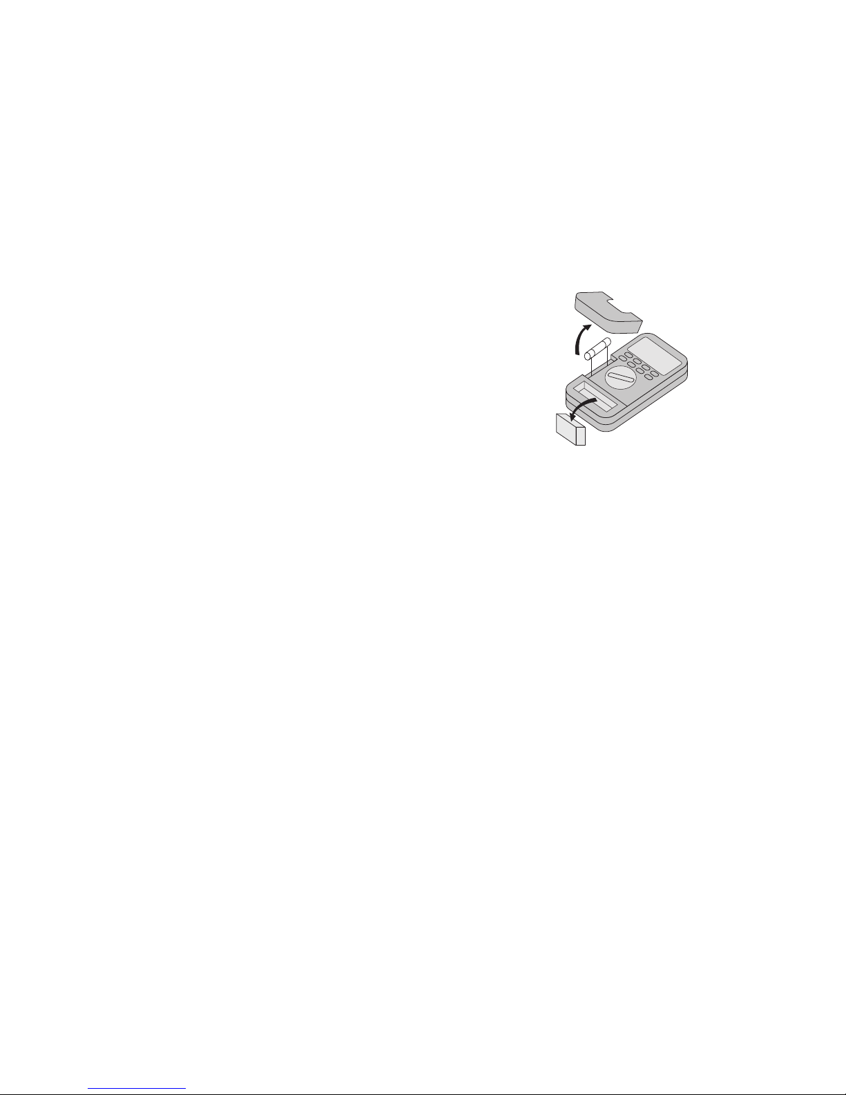
9V Battery
Fuse
20 A 250 V
10
6. COM (-) input socket (COM- or negative connection)
7. V-Ohm-(+) input socket (= positive connection)
8. Capacity or temperature measurement socket. Using this socket
(uncharged!) capacitors and also temperatures (using the available optional NiCrNi probe) can be measured.
9. RS-232 interface for the connection of an interface cable for
data transfer to an IBM compatible Windows 95 PC.
5. Using the multimeter
5.1Fitting the battery – changing the battery and
testing the fuses
5.1.1 Fitting the battery – changing the battery
In order for your measuring device to function perfectly, it must be
fitted with a 9V dry cell battery. When the battery change symbol
appears in the display the battery must be replaced. To do this,
proceed as follows:
Disconnect the measuring instr ument from the circuit being measured, remove the test leads from the instrument, switch it off,
remove the holster (if present) and loosen the two captive fixing
screws on the underside of the case with a suitable screwdriver.
Now carefully remove the sockets cover (if necessary with a thinbladed screwdriver). In addition note the following diagram. Disconnect the used battery from its connecting clip and replace the
battery with a fresh one of the same type. Remember to push the
sheath, if present, onto the battery again.
After successfully replacing the battery place it in the battery compartment and carefully close this once more. Take care that the
connecting clips leads do not become crushed.
Page 7

13
Attention!
Never exceed the input levels, as in this can cause damage to the
measuring device, and can endanger the user.
5.4 Positioning the measuring instrument (sloping position) or
position of use Always operate the multimeter so that the
liquid crystal display (LCD) can be read and the digital
display is facing upwards. There is a fold-out bracket on the
rear of the instrument for better readability in upright
operation.
5.4 Commissioning
5.4.1 Basic settings
The measuring instrument is switched on by turning the rotary
switch to the desired measurement function. "Normal" measurements can now be carried out without additional functions.
To select such an additional function, operate one of the buttons
in the button panel.
5.4.2 Connector & socket configuration and switch markings
a)Connector for capacity and temperature measurement (polari-
sed "+" and "-")
Place a (discharged!) capacitor correctly polarised in the sockets.
Ensure that the connections are long enough, because otherwise incorrect measurements can occur.
For temperature measurement plug the connections of a K-type
thermocouple element (NiCrNi) with the correct polarity into
the marked sockets.
b)Type of operation switch = measurement function switch (10)
12
The measuring instrument has a special function which enables
the built-in fuses to be checked before each measurement for
soundness (whether "blown" or intact). For this, proceed as follows:
- Position the rotary switch to " / " (Continuity check/Diode
test)
- Press the yellow button once. The word "FUSE" appears in the
display.
- Connect "only" the red measuring lead to the V/Ohm/F socket
of the multimeter.
- Touch the metal insert of (deep within) the uA/mA socket with
the probe). Should an acoustic signal sound and the bar graph
indicate a minimum, the fuse (800 mA, quick-acting) is in
order . In case not, the fuse is defective. In this case, replace the
fuse with new.
- Next, touch the metal insert of (deep within) the A socket with
the probe). Should an acoustic signal sound and the bar graph
indicate a minimum, the fuse (20A, quick-acting) is in order. In
case not, the fuse is defective. In this case, replace the fuse
with new.
5.2 Connecting the instrument leads
Always use only the supplied measuring leads for making measurements. Before each connection note the condition of the
connecting plug and test prods and check the insulation for damage. These measuring leads are intended for voltages up to 1500 V
max. The measuring instrument, the VC 350E is designed for voltages up to 1000 VDC or 750 VAC rms max. Take particular care
when dealing with voltages greater than 25 V AC or 35 V DC.
Page 8

15
Switch to temperature measurements with yellow
button
A/TEMP°F = DC and AC current measurements up to 20 A max.
or temperature measurements in °F, Auto-Range
and manual range selection possible; Switch to
temperature measurements with yellow button
c) 20A socket
For DC or AC current measurements up to 20 A max. (!), the red
measuring lead must be plugged in here.
Attention!
The measuring function switch must not on any account be positioned on voltage measurement (mV or V) during current measurement.
d) mA socket
The red instrument lead should be plugged in here for direct
or alternating current measurements up to 400 mA max., but
only if the measuring function switch is set to "4mA" or
"400mA".
e) COM = common socket
the black measuring lead must be plugged in here for all measurements except temperature and capacity measure-ments
(common socket means minus "-" or ground socket)
f) V/Ohm socket
the red measuring lead must be plugged into this socket to
carry out voltage, frequency or resistance measurements, continuity checks or diode tests.
14
Attention!
The type of operation switch may not under any circumstances be
moved during measurements, because otherwise the measuring
instrument can be destroyed and it can endanger the user's life.
Arranged in the full circle, the different measuring ranges can be
selected by turning the switch:
OFF = switch the measuring instrument off when measu-
rements are completed
V = Volt AC/DC Both Auto-Range and manual range
selection (R-H) is possible
mV DC = millivolt DC (milli = 10 exp.-3) only a mV DC volta-
ge range up to 400 mV max.
Ohm = resistance measurement range; both Auto Range
and manual range selection (R-H) possible
"
/
" = continuity check / diode test - no Auto Range and
no manual range selection possible, switch to the
respective function with the "blue" button FREQ =
frequency measurement - no manual range selection (with R-H) possible
CAP = uA= uA AC/DC measurement (u = micro = exp.-6),
Auto Range and manual range selection possible
uA = uA AC/DC measurement (u = micro = exp.-6), Auto
Range and manual range selection possible
mA/TEMP°C = mA AC/DC or temperature measurements in °C,
Auto Range and manual range selection possible;
Page 9

17
- As soon as the test probes are removed from the measurement
point, the small display returns to "0000", while the set reference value remains visible in the main display.
D) COMP (= Comparison)
In this sub-function, a high/low comparison can be carried out, in
which the highest and lowest stored reference value can be compared with the present measured value.
The main (large) display shows "Lo", when the present measured
value is smaller than the lowest stored (preset) reference value.
"Hi" is displayed when the present value is greater than the highest stored reference value. When the present measured value lies
between the upper and lower set limits, "Pass" is displayed. The
actual measured value is given in the small display. This function is
not available for frequency, capacity or temperature measurements. To use this function, proceed as follows. There are two
methods to input or set the comparison values.
Possibility 1:
D1) As under reference value measurement, the range in which
the comparison measurement is to be performed must first be
set; For this, press the "R-H" button until the desired measurement range is set.
D2) Then, press the button "COMP" until the rightmost digit in
the main display flashes. Should the button be pressed only
briefly, instead of the set mode "Err" (Error) appears in the
display. In the small display "Hi" (High = upper comparison
value) appears.
D3) Now set the desired upper limit for this digit with the buttons
" REL" and " R-H" Then, press the "COMP" button once
more.
16
5.4.3 Display-explanation and symbols
A) Digital display
The display can display up to "4000" and (-) polarity is auto-matically indicated (for negative voltages or reversed polarity). There
are also three decimal point positions.
B) Analogue bar graph
The analogue bar graph consists of 43 segments. It has a slightly
higher measuring speed than the digital display. This enables measured value trends to be more easily recognised, as with an analogue multimeter, but without its mechanical disadvantages (damping of the measurement indicator).
If the measurement range is exceeded, then "OL", for Overload, is
displayed.
C) REL (= Relative)
This function enables so-called reference value measurements, in
that the present measured value is displayed in the "small" display
and the difference in the main display. This function is not available under frequency measurements, diode tests, continuity checks
and temperature measurements. Additionally, manual range selection "R-H" must be used for "REL" measurements rather than
"Auto Range". To set a reference value, proceed as follows:
- Select the range in which the reference value is to be used; in
addition press the button "R-H" until the desired measurement
range is set.
- Measure for example under voltage measurement a DC voltage
(a battery) of 1.5V. While measuring, press the "REL" button.
The reference value (1.5 V) is now set. Now perform the voltage measurement in comparison with the reference value. The
present measured value at the measurement point is displayed
in the small display, while the difference between the set reference value and the present measured value is displayed in the
main display.
Page 10

19
Possibility 2:
D1) Carry out steps D1) and D2) in "Possibility 1". Then touch with
the test probes the point to be measured, the value of which
is to be set as the upper limit (Hi).
Press the button " REL" until the desired value is displayed
in the main display. At the same time the rightmost digit
remains flashing. Now remove the test probes from the points
of measurement. Press the "COMP" button four times, until
"Hi" disappears from the small display and instead "Lo"
appears.
D2) Connect the test probes to another point to be measured ,
which is to be set as the lower limit (Lo). Now press the " RH" until the desired value appears in the main display. Here,
too, the rightmost digit remains flashing. Remove the test
probes from the (second) point to be measured. Press the
"COMP" button four times, until "Lo" disappears from the
small display and the comparison measurement begins. In the
absence of an applied measurement signal, "Lo" is displayed,
with in addition "0000" in the small display. Under resistance,
diode test and continuity check measurements "Hi" appears
in the main instead of "Lo". In the small display "OL" (Over
load) appears instead of "0000".
D3) Connect the test probes to the measurement point, the value
of which is to be set as the comparison measurement value. If
the present measured value shown in the small display is
lower than the set lower comparison value, then "Lo"
appears in the main display. If the present measured value lies
above the set upper comparison value, "Hi" appears in the
main display. If the present measured value lies between the
set upper and lower comparison values, "Pass" appears in the
main display.
D4) To be able to leave the function, the measuring instrument
must first be removed from the measurement circuit and the
rotary switch then moved to another switch position.
18
D4) The next-left digit flashes. Proceed as described in c) until the
whole "Hi" comparison value is set.
D5) Press the yellow button once "COMP". The upper limit value
"Hi" is stored in memory, "Hi" disappears from the small display and "Lo" (Low = lower comparison or limit value)
appears in its place. Once again the rightmost digit flashes.
D6) Carry out the setting of the lower limit values as described in
c. Then, press the "COMP" button once again. The comparison
measurement begins. In the absence of an applied measurement signal, "Lo" is displayed, with in addition "0000" in the
small display.
Under resistance measurement, diode test and continuity
check, "Hi" appears in the main display instead of "Lo". In the
small display "OL" (Overload) appears instead of "0000".
D7) Connect the test probes to the measurement point, the value
of which is to be set as the comparison measurement value. If
the present measured value displayed in the small display is
lower than the lower comparison value set, then "Lo"
appears in the main display. If the present measured value lies
above the set upper comparison value, "Hi" appears in the
main display. If the present measured value lies between the
upper and lower comparison values set, "Pass" appears in the
main display.
D8) To be able to leave the function, the measuring instrument
must first be removed from the measurement circuit and the
rotary switch then moved to another switch position.
Note
Negative measured values cannot be set.
Page 11

21
Note
The measurement values are reproduced as they wer e stored (e.g.
voltage values in "V" while in resistance measurement), independently of the measurement function setting.
F) R-H (= Range Hold)
In this function the automatic range selection (Auto Range) can be
switched off and the measurement range set by hand (manually).
The "AUTO" symbol disappears from the display as soon as the
button is first pressed. With each further press of the button
" R-H" the decimal point is shifted one position to the left or
right and the units of measurement change correspondingly.
To leave this function press the " R-H" button until "AUTO" is
displayed in the upper display strip again.
G)Auto Hold - MIN - MAX function
The "Auto-Hold" function enables a measurement value to be
"frozen" / held for later use, e.g. in measurement processes. With
the MIN function, the lowest measurement value appearing is
automatically stored. With the MAX function, the highest measurement value appearing is automatically stored. The special function(s) is(are) not useable under temperature, capacity or frequency measurements. While using the special function, the
"Auto Range mode" (automatic range selection) is in addition not
active.
It is therefore necessary to set a specific measurement range for
this special function beforehand. While using a special function,
this becomes abandoned if the measurement range is changed
manually. To set / activate the special function, proceed as follows:
G1) Connect the red test lead to the respective measurement
socket (but not "COM") of the measurement function with
which the "Auto Hold MIN-MAX" function is to be used.
Connect the black test lead to the "COM" socket.
20
E) MEM (= Memory) and RCLL (= Recall)
With this special function, except under temperature t measurement, up to 8 reference values can be stored
and called up / reproduced. Measurement values of different
measurement functions can also be stored, such as DC voltage in Memory 1, resistance in memory 2 and so on. To do this,
proceed as follows:
E1) Performing measurements. Each time a certain value is to be
stored, no matter in what measurement function (except temperature measurement), press the "MEM" button. As a result,
two numerals separated by a space appear in the small display. The left one shows the memory location at present being
reproduced ("0" when "RCLL" button not yet pressed), the
right one shows the verifiable / specifiable memory locations.
E2) When the first measurement value has been stored by pres-
sing the "MEM" button, this is verified by the number "1". Up
to eight (8) measurement values can thus be stored. When all
memory locations are filled, the number 8 is displayed on the
right in the small display.
E3) When one of the eight stored values is now to be used, the
"RCLL" button must be pressed. Every time the "RCLL" button
is pressed, the next-higher memory location opens.
The stored measurement value is thereby read out. The
memory location currently being read is given in the left row
of numbers from 1 to 8.
E4) To be able to leave the Store/Recall function without losing
the stored values, turn the rotary switch, but not to "OFF". To
erase the stored values, either press the "MEM" button or
turn the rotary switch to "OFF".
Page 12

23
Note
So that under resistance measurement, diode test and continuity
check a "MIN" measurement is possible at all, either the test probes must be held together ("short-circuited") or a resistance measured. Only then can the "REC" button be pressed, and only then
does the symbol "A-H" disappear from the display, or only then
does the symbol "MIN" appear in the display. When "MIN" is visible, normal measurements (under resistance measurement, continuity check and diode test) can be proceeded with. This procedure is not required with other measurements.
Now connect the test probes to the circuit (points) to be measured. The present measured value appears both in the large
and small displays. Now remove the test probes from the test
points. The most recently measured value remains frozen
(held) in the large display. In the small display, "OL" appears
under resistance measurement, continuity check and diode
test. "0000" appears in the small display under the other measurement functions. The measurement value now remains
frozen/held in the large display until a smaller value is established during a further measurement. The large display
always displays the smallest occurring measured value.
G6) When the MAX function is to be used and the instrument is in
the "MIN" function mode, press the "REC" button once
again. The "MIN" symbol disappears and in its place the
"MAX" symbol appears to its left. When, however, the instrument is at present in "Auto Hold" mode, press the "REC" button twice. When the "Auto Hold" mode is also deactivated,
the REC" button must be pressed three times.
22
G2) Set the rotary switch to the desired measurement function
(but not to one of those mentioned as not available).
G3) Switch off the "Auto Range" function while setting the desi-
red measurement range by hand (= manually) with the button.
G4) When the Auto Hold function is now to be used, press the
"REC" button. The symbol "A-H" appears in the so-called
headline of the display. "0000" appears in the small display
and in the main display, independently of the range setting.
With the measurement functions diode test, resistance measurement and continuity check, "OL" for overload or overrun
appears in the small and large displays instead of "0000".
Connect the test probes to the circuit to be measured. The
present measurement value appears both in the small and
large displays. Now remove the test probes from the points of
measurement. In the large display the most recently measured value remains frozen / held. In the small display, "OL"
appears under resistance measurement, continuity check and
diode test. Under the remaining measurement functions
"0000" appears in the small display.
When a new measurement is now made, the value displayed
in the large display remains held for another approx.
4 seconds, before it disappears or a new measurement value
is displayed.
G5) When the MIN function is to be used while the "Auto Hold"
function is presently in use, press the "REC" button once
again. The symbol "A-H" for Auto Hold disappears from the
headline as a result and in its place the symbol "MIN" appears
beneath. When however the "MAX" mode is presently in use,
or the "Auto Hold" mode is not in use, the "REC" button must
be pressed twice.
Page 13

25
The setting / changing of the respective alternate value is
done with the " REL" or " R-H" button. Having successfully
made the setting, press the yellow button again.
H2) To activate (switch on) the printer port, before switching on
the measuring instrument (by means of the rotary switch) the
"REC" button and the yellow button must be pressed. After
approx. 2 to 3 seconds release the yellow button, but continue to press the "REC" button. Now switch on the measuring
instrument and the computer. The printer port is activated.
Every 10 seconds, the measurement data with measured
value, measurement range and measurement unit will now
be printed out via the connected serial printer. To switch the
printer port off again, position the rotary switch to "OFF".
H3) To switch off the Auto Power Off function, before switching
the measuring instrument on (by means of the rotary switch),
press the blue button. After approx. 2 to 3 seconds release the
blue button and immediately afterwards, switch the measuring instrument on by means of the rotary switch. The measuring instrument will now not switch off after approx. 13
Min., but rather remain operating until either the battery is
empty (used up) or the rotary switch is set to "OFF" (instrument off). If the measuring instrument is switched off by
means of the rotary switch and afterwards switched on again,
the Auto Power Off function is reactivated, i.e. the instrument
switches off automatically after 13 minutes.
5.4.4 Display information or symbols about the operating modes
a) Battery change indicator
An alkaline 9V battery in this measuring instrument lasts on
average approx. 400 hours. Approx. 8 hours before the battery
"expires", the battery change symbol appears in the display.
+
-
24
Note
The "MAX" measurement procedure is similar to the "MIN" measurement. Proceed as described in "Note" under "MIN" measurement.
Now connect the test probes to the circuit (points) to be measured. The present measured value appears both in the large and
small displays. Now remove the test probes from the test points. In
the large display the most recently measured value remains "frozen" (held). In the small display, "OL" appears under resistance
measurement, continuity check and diode test. "0000" appears in
the small display for the other measurement functions. The measurement value now remains frozen/held in the large display until
during a further measurement a higher value is established. The
large display always displays the highest-occurring measured
value.
H) "Device on" special functions
When the instrument is switched on, various special functions can
be activated. For example the "measurement frequency" for alternating current - or AC voltage measurements can be changed
from 50 Hz to 60 Hz and vice versa. It is also possible to connect a
serial printer and to activate the printer port by means of the
"Device on" function. With the last of the three "Device on" special functions, the "Auto Power Off" function (automatic switchoff after approx. 13 minutes) can be turned off. When one of
these special functions is to be activated, proceed as follows:
H1) To be able to change the measurement frequency, the yellow
button must be pressed and held when switching on the measuring instrument (by means of the rotary switch) and released after approx. 2 to 3 seconds. As a result "50 Hz" or "60
Hz" appears in the display according to the previous setting.
Page 14

27
Cause Remedy
Measuring instrument Read through the operating
not operating instructions thoroughly.
Is the battery unused?
The battery is in order, but Are the fuses in order?
no current measurement Check the fuse(s) per 5.1.2. Are the
possible fuses clipped in the holder(s)?
6. Performing measurements
General:
The multimeter is not protected against the test leads being
connected to the wrong measuring socket as a function of the respective measurement function. It can be damaged or destroyed.
To safeguard against this, a so-called acoustic socket alarm is built
into this multimeter, which together with the selected measurement function (voltage, frequency, resistance or capacity measurement, etc.) reproduces various signal sequences. If for example the
red test lead is in one of the current measurement sockets (uA/mA
or A) and the black test lead in the COM socket but the rotary
switch is not set for current measurement, then the following
acoustic signals are hear:
V AC/DC : ——————— (continuous tone)
mV DC/FREQ : - - - - - - - - ("slowly"-interrupted tone)
Ohm / /->l- : - - - - - - - - - - - ("quickly"-interrupted tone)
CAP : (no acoustic signal)
Note
Should other test leads be used instead of those supplied with
the measuring instrument, the socket alarm does not function.
26
Between each individual measurement cycle, a battery check is
carried out.
b) All other symbols, which stand for the various units of measu-
rement:
AC = Alternating Current
DC = Direct Current
mV = Millivolt (exp.-3)
V = Volt
uA = Micro-Ampere (exp.-6)
mA = Milliampere (exp.-3)
A = Ampere
kHz = Kilohertz (exp.3)
MHz = Megahertz (exp.6)
°C = Degrees Celsius
°F = Degrees Fahrenheit
uF = Microfarad (exp.-6)
nF = Nanofarad (exp.-9)
kΩ = Kiloohm (exp.3)
MΩ = Megaohm (exp.6)
5.5 Fault finding
If the multimeter is not functioning correctly, the following causes
may be responsible:
Page 15

29
Each of the voltage ranges, whether AC or DC, possess an input
impedance of 10 MOhm in parallel with < 100 pF). The AC voltage input is AC-coupled. As soon as a "-" appears in front of the
measured value in a direct voltage measurement, the measured
voltage is negative (or the instrument leads are switched).
Notes
- Due to the fact that the measurement input is very sensitive, it
may be that certain measured values are displayed even with
test leads unconnected (not connected to a circuit). This occurrence is normal and will disappear as soon as measurements are
performed.
- In the "mV DC" measurement range, no "Auto Range" (automatic range selection) is available.
6.2 Current measurement
To measure direct or alternating currents, procedure is as follows:
1. Connect the red test lead to the A or uA/mA socket and the
black test lead to the COM socket.
2. Position the rotary switch to current measurement (uA, 4000 uA
max.; or mA, 400 mA max.; or A, 20 A max). In the current measuring range both automatic ("Auto Range") and manual range
selection ("R-H") is possible.
3. Press the blue button according to whether DC or AC current is
now to be measured. As soon as "AC" appears in the display,
alternating current mode is selected.
4. Open the unpowered circuit to be measured (switch off circuit
to be measured) and connect the test lead(s) in series with the
unpowered circuit to be measured (see following diagram).
28
6.1 Voltage measurement
Attention!
The maximum permitted input value must not be exceeded under
any circumstances. MAX. 1000 VDC or max. 750 VAC rms.
Do not touch any circuits or circuitry components when measuring voltages higher than 25 VACrms or 35 VDC. The measuring
instrument may only be used in installations of Overvoltage category II.
To measure direct or alternating voltages, the procedure is as follows:
1. Connect the red instrument lead with the V/Ω socket and the
black instrument lead with the COM socket.
2. Set the rotary switch to the desired position (V) or, only for DC
voltage measurements, also to "mVDC".
3. Press the blue button according to whether DC voltage or AC
voltage is to be measured (except for mV DC). As soon as "AC"
appears in the display, the instrument is in AC measurement
mode.
4. Connect the test probes with the test object (load, circuit, etc.).
Attention!
Because the metal inserts of the socket contacts sit relatively deeply (on grounds of safety), it is imperative that the measuring
lead plugs are inserted into the respective sockets up to their
stops. Make sure that the test lead plugs are securely connected
to the measuring instrument before a supposedly "0V" measurement has been performed and circuit components then touched.
Attention!! Life can be endangered if volt
ages of more than 25 VAC rms or 35 VDC are touched.
Page 16

31
symbols appear in the display: "OL", " " and "Ω". Should the
symbols not appear, press the blue button once.
3. Then connect the test probes with the absolutely voltage-free
test points.
Depending on the circuit resistance present, the following acoustic signals are heard:
————————— (continuous tone) with 30 Ohm or less
— — — — — — — ("quickly"-interrupted tone) with more than
30 Ohm and less than 106 Ohm
————- ———- ("slowly"-interrupted tone) with more than
106 Ohm and less than 1700 Ohm
Attention!
Do not measure charged capacitors, as a possible discharge may
damage your measuring device.
The indicated measured value is not the "true" resistance value.
To establish this, a resistance measurement must be carried out
(as follows).
6.4 Resistance measurement
Attention!
Ensure that all circuitry components, circuits and structural elements to be measured, as well as other test objects, are completely voltage-free.
For measurement of voltage-free resistance up to max. 40 MOhm
proceed as follows:
30
5. Power up the circuit to be measured (circuit, power, etc.) and
read the measured current. Whenever a "-"appears in front of
the measured value, this indicates a direct current or the measured value is negative or the test leads reversed.
Attention!
Do not measure any currents in circuits in which voltages greater
than 250 VDC or VAC rms can occur, so that the measuring device
is not damaged and your life is not endangered as a result. Under
no circumstances should currents over 20 A be measured. Measurements should only be made in 16 A-fused current circuits or
those in which powers greater than 4000 VA cannot occur.
Measurements of currents equal to 20 A must only be measured
for a maximum of 10 s duration and must only be performed in
intervals of 15 minutes (cooling down phase for the shunt).
6.3 Continuity checking and diode test
With this function voltage-free leads, fuses, circuits etc. can be
acoustically checked for continuity. This measurement is per-formed as follows:
1. Connect the red instrument lead with the V/Ω socket and the
black instrument lead with the COM socket.
2. Position the rotary switch to / . As a result the following
A
DMM
Consuming
device,
load, circuit
Current
source
Page 17

33
3. Now connect the test probes to the test points, an unpowered
semiconductor circuit, with the red probe to the anode and the
black probe to the cathode (these usually being indicated by a
coloured ring, spot or similar).
To check a diode path in the conducting direction, a voltage of
approx. 0.25 V (germanium) or 0.7 V (silicon) will be measured,
provided that the diode path is not defective.
When the test probes are reversed, i.e. red to the cathode and
black to the anode, then the high resistance direction of the
diode path will be checked.
If "OL" is displayed, the diode is serviceable. If on the contrary
a value between 0 V and "OL" is displayed, either the test points
have been incorrectly chosen or the diode is faulty.
The test voltage under diode test is sufficient to cause most (low
current) LEDs to emit light. With LED operating voltages of
more than 2.0 V, however, the DMM can incorrectly indicate
that the LED is faulty.
Attention!
During the diode test, ensure that the diode and circuit in which
it is installed are completely voltage-free. Any capacitors must be
discharged.
6.6 Frequency measurement
Attention!
It is essential to observe the max. input levels!! Do not connect
any voltages greater than 250 VDC or VAC rms max. With voltages greater than 25 VAC or 35 VDC, there is danger to the user in
the event of contact.
32
1. Connect the red instrument lead with the V/Ω socket and the
black instrument lead with the COM socket.
2. Position the measurement function switch to resistance measurement (Ohm).
3. Then connect the test probes with the absolutely voltage-free
test points. Auto Range sets the appropriate measurement
range, to produce the smallest possible measurement error.
The resistance of the test leads can normally be ignored (approx.
0.1 to 0.2 Ohm). However, even this low value can lead to inaccu-
racies in the 400 Ohm measurement area. To compensate for these
"measurement errors", the REL function (described under 4.4.3.C)
can be used.
When resistance measurements are performed, take care that the
test points which are to be touched with the test probes are free
from dirt, oil, solder flux or similar. Such conditions can falsify the
measured value.
With resistances greater than approx. 4 MOhm the display can
take some time to become stabilised. As soon as "OL" appears in
the display and the bar graph flashes, the measurement range has
been exceeded, or the circuit being measured is open circuit/high
resistance (> 40 MOhm).
6.5 Diode test
For measurement of unpowered semiconductor circuits (diodes,
transistors, rectifiers, etc.), proceed as follows:
1. Connect the red test lead to the V/Ω socket and the black test
lead to the COM socket.
2. Set the rotary switch to " / " and press the blue button
once. The following symbols are shown in the display: The diode
symbol "->l-", "mV" and "OL " (for overload or here: "infinitely-high resistance"). Manual range selection is not possible.
Page 18

35
To measure the capacity of capacitors, proceed as follows:
1. Discharge every capacitor, before connecting it to the measuring instrument. Do not measure charged capacitors, otherwise
the measuring instrument can be damaged.
2. Set the rotary switch to "CAP".
3. Measurements can now (only) be performed with the connec-
tors on the measuring instrument. With polarised capacitors,
observe the correct ("+" and "-") polarity. Take care that
connecting "legs" are sufficiently long and not too thin (weak).
Should the "legs" be too short and thus not be in contact or if
the capacitor is faulty, a capacity of approx. 00.11 nF is displayed.
6.9 Temperature measurement
The temperature display ranges from -40°C to +1000°C, that is
from -40°F to 2000°F, with the optionally-available measuring
probe. Temperature measurement is carried out exclusively with a
K type (NiCrNi) thermocouple. When no temperature probe is
connected to the measurement socket on the measuring instrument, the present room temperature (ambient temperature. To
perform a temperature measurement, proceed as follows:
1. Position the measurement function switch either to "mA/
TEMP°C" or "A/TEMP°F" and press the yellow button once.
2. Connect the thermocouple plug, correctly polarised (narrow
and wide contact blades) to the CAP/TEMP measurement
socket.
34
While measuring system voltages greater than 25 VAC or 35 VDC,
do not move the rotary switch to another measurement function). The sensitive electronics within the measuring instrument
can otherwise be destroyed, as a result of which the user can be
endangered.
To measure a frequency, proceed as follows:
1. Connect the red test lead to the V/Ω socket and the black test
lead to the COM socket.
2. Position the rotary switch to "FREQ".
3. Connect the test probes to the points to be measured (genera-
tor output, etc.).
Note
To perform a measurement with maximum accuracy, use a BNC
screened cable where possible (adapter available) for the measurement, to avoid error measurements caused by radiated fields.
For frequency measurement, it is not possible to use manual range
selection!
6.7 Capacity measurement
Attention!
When short-circuiting capacitors, high-energy discharges can
occur. Attention - danger to life! Do not touch the connectors of
capacitors with voltages over 35 VDC or 25 VAC. Take care in spaces in which dust, inflammable gas, steam or liquid is present or
can occur. ==> Danger of explosion!
Page 19

37
3. Click on the "START" (bottom left, on the taskbar) with the
left mouse button: and then click on "RUN".
4. As a result, a dialog box appears into which "A:\Setup.exe"
should be entered. Click on OK". Follow the on-screen setup
program instructions.
5. Once the program has successfully loaded, click on "OK".
Step 2
The software for Windows 95 is now loaded. To "communicate"
with the multimeter, the following inputs/actions are now required:
a) Connect the interface lead 4-pin plug (supplied) to the RS-232
interface on the (switched off) measuring instrument. Connect
the other end of the interface lead to a free serial port on the
(switched off) computer.
b) Power up the PC. Open the START window under Windows ‘
95. Click the mouse pointer on the Programs menu item using
the left mouse button. Among others in the sub-directories
listed is "DMM97". Click on OK „97". Thereupon "About
Scope View" is displayed. Click on OK.
c) The menu "Scope View Main Menu" is displayed. To install or
change the hardware configuration, click on "Setup". "Scope
View Setup" appears on-screen. Enter the following information:
Meter Model 350E
Com Port COM1, COM2, etc. (communications interface
on the PC)
Baud rate 1200 (transfer speed 1200 bits per second)
d) Having inputted the data, store the data "permanently" by
clicking on "SAVE" and then on "CLOSE" to close the window .
36
Attention!
Do not connect any voltages. The instrument can be destroyed by
this.
6.10 Using the analogue bar graph
The bar graph is easy to operate and understand. It is comparable
with the pointer of an analogue measuring instrument without its
mechanical disadvantages. It is particularly suitable for measuring
signals that change rapidly, for which the digital display is too
"slow". So the trends of a measured value change can be quickly
recognised and evaluated.
6.11 Using the multimeter in connection with a computer
The multimeter is supplied together with a diskette, on which is
software for DOS and Windows 95 operation. So that the measuring instrument can communicate with an IBM compatible PC, the
software must first be installed.
Note
The following installation(s) presuppose basic knowledge of the
various MS DOS commands and an available hard disk. Read the
MS DOS manual with regard to software installation, if you have
no or insufficient basic knowledge of MS DOS commands. In addition, a VGA monitor (+ VGA card in the computer) is required to
operate the software.
Step 1
1. Start your computer and activate Windows. Windows 95 (nor-
mally) loads automatically.
2. Under Windows, insert the floppy disk into the 3.5" drive (A
or B according to the installation).
Page 20
39
Notes
Should there be no hard disk available, it is possible to start
the program from the floppy disk: Change to the drive in
which the floppy will be run.
Change to the "DOS" subdirectory on the floppy, type "DMM"
and press Enter.
To stop the program, or if an "ERROR" occurs, perform a warm
boot (Control, Alt, Del keys).
Step 4
The following defines the communication parameters.
Transfer rate : 1200 baud
Character code : 8-bit ASCII
Parity : none
Stop bits : 1
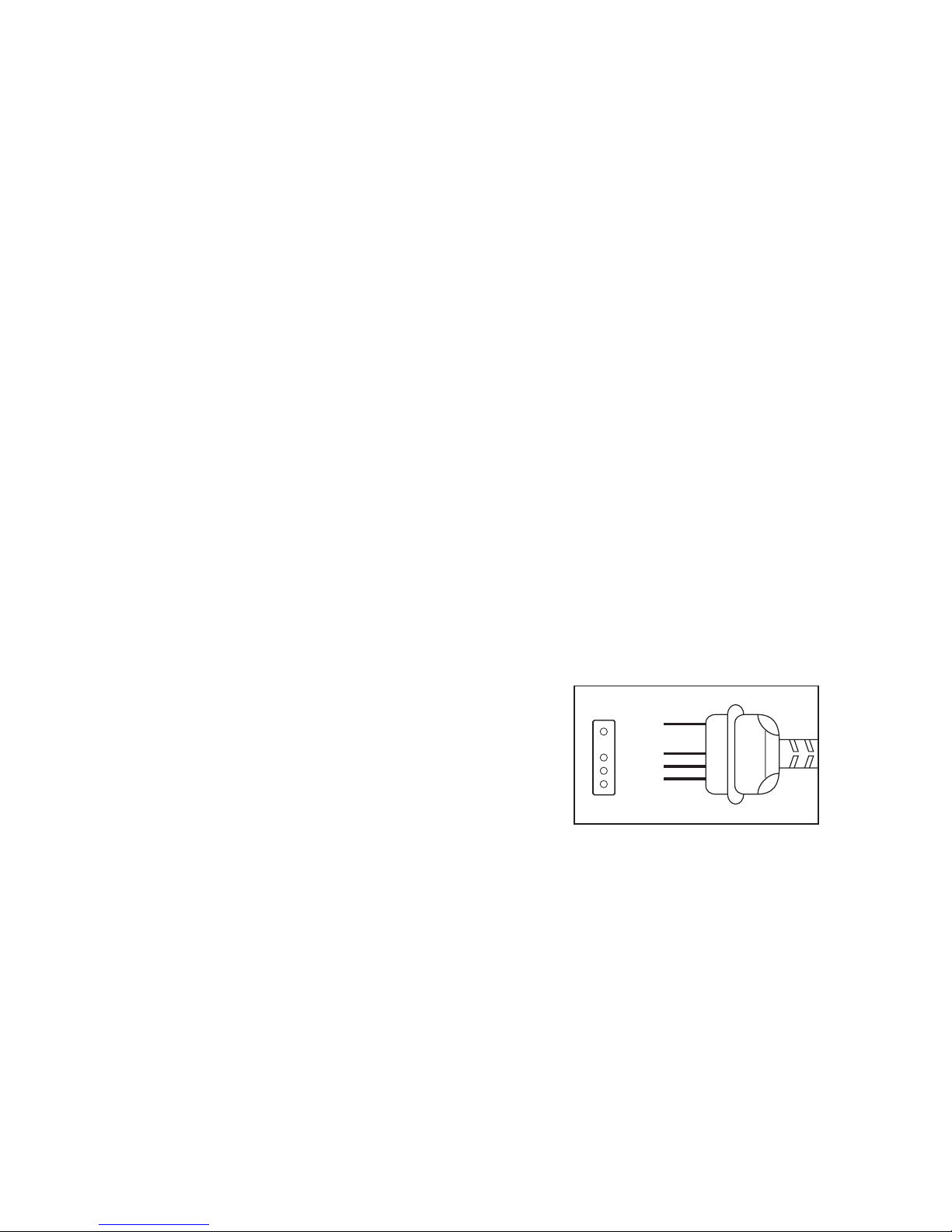
Step 5
The configuration of the measuring instrument interface is as
follows:
Data transfer between the measuring instrument and the
computer is bi-directional.
RXD
RS-232C
GND
TXD
DSR
RTS
38
e) To run the PC program, click on "OFF" in the bottom right of
the menu box.
Step 3
Use of MS DOS software is described below:
a) Switch on the computer and measuring instrument. The MS
DOS program is named METER.
Note
The following installation(s) presuppose basic knowledge of the
various MS DOS commands and an available hard disk. If in-adequate or no basic knowledge of MS DOS commands is available,
refer to the MS DOS manual concerning software installation. In
addition, a VGA monitor (+ VGA card in the computer) is required
to operate the software.
1. Insert the floppy disk into the appropriate disk drive (A or B or
similar).
2. Make a directory on the hard disk (usually "C") with the name
"METER".
cd\ [Enter]
md METER [ENTER] [ENTER] = Press the "Enter" key.
3. Change to drive A (or B, etc., according to the installation). Call
the file METER and press ENTER key, e.g.:
cd METER
4. Copy the files from the floppy to the hard disk:
copy a:\DOS c:
5. In order to start the program, enter "DMM" and press "Enter".
After that, follow the on-screen instructions.
Page 21

41
Input impedance ..................: 10 MΩ in parallel with 100pF (VDC
and VAC)
Overload indicator ...............: "OL" is displayed for overload
Operating temperature........: 0°C to +40°C, with relative humidi-
ty <75%, non-condensing
Storage temperature............: -10°C to +50°C, with relative humi-
dity <75%, non-condensing, battery not installed
Temperature for guaranteed
accuracy.................................: +23°C ±5K
Battery change indicator.....: " " is displayed
Battery type ..........................: NEDA 1604 9V or 6F22 9V, alkaline
type
Weight...................................: approx. 364 g (with 9-V battery)
Dimensions (L X W X H).......: 189 x 90 x 38 mm
8.2 Measurement tolerances
Statement of accuracy in ± (% of the reading + number of digits).
Accuracy 1 year at a temperature of +23°C ± 5°C, with a relative
humidity of less than 75 %, non-condensing. The warm-up time
is 1 minute.
+
-
40
7. Maintenance and calibration
To guarantee the accuracy of the multimeter over an extended
period of time, it should be calibrated every twelve months
(calibration service available at Service 2000).
Changing a fuse is described under 3. 3. (Safety requirements).
Battery changing can be found under 5.1.1.
To clean the instrument or the display window, use a clean, lintfree, anti-static, dry cleaning cloth.
Attention!
Use no carbonaceous cleaners, petrols, alcohols or similar for
cleaning. Otherwise the surfaces of the clip adapters / test leads
can be attacked. In addition, the vapours are explosive and
damaging to health. Do not use any sharp-edged tools, screw
drivers, metal brushes or similar for cleaning.
8. Technical data and measuring tolerances
8.1 Technical data
Display .................................: 33/4-position LCD display up to
4000 (3999), with automatic polarity indication
41/2-position for frequency measurements
41/2-position "small" display
with analogue bar graph display
(bar segment display)
Maximum measuring rate...: 2.5 measurements per second
Max. input current AC/DC...: 20 A
Page 22
43
8.3 Maximum inputs
Voltage measurement : 1000 VDC or 750 VAC
Current measurement : 20 A AC/DC in A range,
400mA AC/DC in mA range
Resistance : 40 MOhm, overload-protected:
measurement 250 VDC/VAC rms
Frequency : 2 MHz, with max. 250 VDC/ VAC rms
measurement input voltage
Attention!
The functions capacity and temperature measurement,
continuity check and diode test are not protected against
overload or excessive input voltage(s). Exceeding the maximum
permitted input will result in damage to the measuring
instrument or can endanger the user’s life.
42
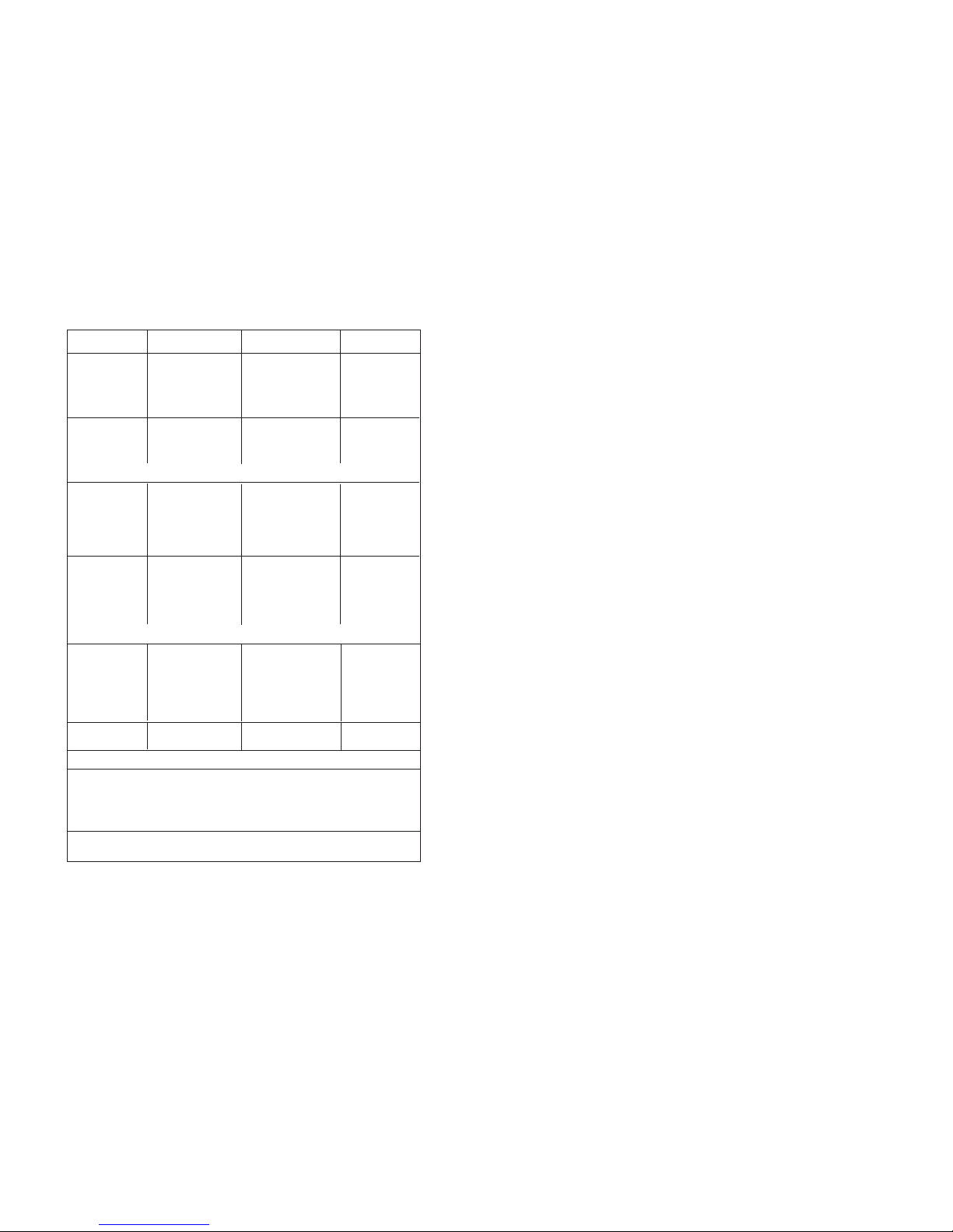
Operation
Measuring
range
Accuracy
Resolution
DC voltage 400 m V ±(0.3%+2dgts) 100 u V
4V ±(0.3%+1dgt) 1 m V
40 V ±(0.3%+1dgt) 10 m V
400 V ±(0.3%+1dgt) 100 m V
1000 V ±(0.5%+2dgts) 1 V
AC voltage 4 V ±(0.8%+3dgts) 1 m V
40 V ±(0.8%+3dgts) 10 m V
400 V ±(0.8%+3dgts) 100 m V
750 V ±(1.2%+5dgts) 1 V
Direct 400 u A ±(0.5%+2dgts) 0.1 u A
current 4000 u A ±(0.5%+2dgts) 1 u A
40 m A ±(0.5%+2dgts) 10 u A
400 m A ±(0.5%+2dgts) 100 m A
4 A ±(1.0%+5dgts) 1 m A
20 A ±(1.0%+5dgts) 10 m A
Alternating 400 u A ±(0.8%+5dgts) 0.1 u A
current 4000 u A ±(0.8%+5dgts) 1 u A
40 m A ±(0.8%+5dgts) 10 u A
400 m A ±(0.8%+5dgts) 100 u A
4 A ±(1.5%+10dgts) 1 m A
20 A ±(1.5%+10dgts) 10 m A
Impedance 400 Ω ±(0.8%+2dgts) 0.1 Ω
4k Ω±(0.5%+2dgts) 1 Ω
40 k Ω ±(0.5%+2dgts) 10 Ω
400 k Ω ±(0.5%+2dgts) 100 Ω
4MΩ ±(0.5%+2dgts) 1 kΩ
40 M Ω ±(1.0%+10dgts) 10 kΩ
Frequency 40Hz - 1kHz ±(1.0%+5dgts) 1 Hz
1kHz - 2MHz ±(0.3%+1dgt) 10 Hz - 1kHz
Temperature -40°C- +1000°C ± (3%+5dgts) 1°C
-40°F- +1999°F ± (3%+5dgts) 1°F
Capacity 100 nF - 100 uF ± (3%+10dgts) 10 pF - 1 uF
Frequency of AC voltage from 40 Hz to 100 Hz
Frequency of alternating current from: 50 Hz to 1 kHz
Diode test: test current max. 1 mA
Sensibility greater or equal approx. 2Vrms from 40 Hz to 300 Hz
Sensibility greater or equal approx. 500Vrms from 300 Hz to 2 MHz
Page 23

45
• Mesure des résistances jusqu'à une valeur maximale de
40 MOhm
• Mesure des capacités jusqu'à une valeur maximale de 400 uF
• Contrôle de la circulation du courant électrique et test des
diodes
• Mesure des fréquences jusqu'à une valeur maximale de 2 MHz
• Mesure des températures comprises entre -40°C et +1000°C
maximum, ou bien entre -40°F jusqu'à +1999°F (= Fahrenheit)
maximum
• Il est interdit de pratiquer des mesures dans une pièce humide
ou à l'extérieur , en particulier dans un environnement aux conditions défavorables. Des conditions défavorables se définissent comme suit:
- toute forme d'humidité (air trop humide, par exemple),
- la poussière, les gaz inflammables, les vapeurs et solvants,
- vibrations trop fortes,
- champs magnétiques trop puissants, créés à proximité de
machines ou de haut-parleurs,
- electricité statique (champs et décharges).
Une utilisation autre que celle prévue ci-dessus endommagera
l'appareil et pourra provoquer, en outre, un risque électrique
comme un court-circuit, un incendie, une électrocution etc.. Il est
interdit de modifier ou de reconstruire cet appareil dans son
intégralité! Respecter absolument les consignes de sécurité!
2. Introduction, présentation
Le présent Multimètre se trouve équipé de plusieurs
appareillages particuliers qui contribuent à renforcer de manière
rationnelle et intelligente bon nombre d'opérations de mesure:
44
Multimètre numérique VC 350E
Attention! A lire absolument
Lisez avec une attention particulière l'ensemble de la présente
notice d'emploi.. Pour tous dommages provoqués par un nonrespect des consignes du mode d'emploi, vous perdez vos droits
de garantie; en outre, le non-respect des consignes peut vous
mettre en danger de mort!! Nous n'assumons aucune responsabilité pour tous dommages en découlant. Conservez avec le
plus grand soin la présente notice d'emploi.
Table de matières
Page
1. Utilisation conforme à la destination ...................................45
2. Introduction............................................................................46
3. Consignes de sécurité.............................................................47
4. Description des organes de commande................................52
5. Utilisation du multimètre.......................................................55
6. Réalisation de mesures ...........................................................74
7. Entretien et calibrage.............................................................88
8. Donnés techniques et tolérances de mesure........................89
1.Usage conforme à la destination du VC 350
• Mesure des tensions de courant continu jusqu'à une valeur
maximale de 1000 VDC
• Mesure des tensions de courant électrique alternatif jusqu'à
une valeur maximale de 750 VAC
• Mesure des courants continu et alternatif jusqu'à une valeur
maximale de 20 A
F
Page 24

47
3. Consignes de sécurité
• Désignation CE: Le multimètre numérique VC 350E répond aux
normes CEM et correspond à la Directive 89/336/CEE ; il remplit
les conditions de la directive sur les basses tensions 73/23/CEE.
• Cet appareil a été construit et contrôlé en tenant compte des
normes DIN 57 411 Partie 1/VDE 0411 Partie 1, Mesures de
prévention prises pour travailler avec des appareils de mesure
électronique, ou encore de la norme IEC 1010-1. Il a quitté l'usine du constructeur dans un état parfait tant du point de vue
de la sécurité que du point de vue technique. Si l'usager veut
lui conserver cet état tout en s'assurant d'un fonctionne-ment
exempt de risques, il doit absolument respecter les consignes
de sécurité et les avertissements («Attention!» et «Avertissement») contenus dans la présente notice d'emploi. Le sens des
symboles suivants doit être présent à l'esprit :
= Attention! Tensions qui présentent un risque au
contact! Danger de mort!
= Lisez la notice d'emploi
CAT II = Catégorie II de surtension
= Classe de protection II
• Les mesures de courant ne doivent être effectuées que dans
des circuits électriques sous protection de 16 A ou sous tension
inférieure à 250 VDC/VACrms ou avec une puissance inférieure
à 4000 VA. Le multimètre ne doit pas être utilisé pour mesurer
des installations de la Catégorie III de surtension d'après la
norme IEC 664. Ni l'appareil ni ses câbles de mesure ne sont
protégés contre les explosions de l'arc électrique (Norme IEC
031-13-101, Paragraphe 13.101). C'est exclusivement dans une
46
un second écran d'affichage, plus petit, comportant un affichage
à 41/2 positions servant à un affichage simultané de la valeur
enregistrée ainsi que de la valeur momentanément mesurée, un
enregistrement des valeurs mesurées avec une mémorisation
pouvant inclure jusqu'à 8 résultats de mesure, une fonction
dénommée fonction de comparaison afin d'effectuer des
comparaisons entre des résultats de mesure, etc..
Cet appareil de mesure est doté du procédé de réglage
automatique dénommé AUTO RANGE, par l'entremise du quel,
quelle que soit le nombre des mesures effectuées, l'appareil se
règle à chaque fois automatiquement sur la catégorie souhaitée
et adéquate pour la mesure. Quant à la fonction REL, elle permet
des mesures comparatives en regard d'une mesure de référence.
C'est sur le petit écran d'affichage qu'apparaît le différentiel de
la mesure alors que le grand écran présente le résultat de la
mesure courante. Avec la fonction COMP on peut opérer des
mesures comparatives; leurs résultats peuvent indiquer ensemble
la plus haute et la plus faible valeurs de la mesure. La fonction
MEM (pour Memory = enregistrer) et la fonction RCL (pour Recall
= rappeler) rendent possible l'enregistrement/la reproduction
maximum de 8 résultats de mesure à la fois. Par sa fonction
originale de coupure automatique de l'énergie électrique, le
multimètre numérique coupe son alimentation de lui-même s'il
reste pour un espace de temps d'environ 12 minutes sans
fonctionner (étant en Stand by), afin de ne pas gaspiller
inutilement l’énergie de sa pile. Il est très facile de remettre le
multimètre en service après cet arrêt automatique: il faut
d'abord régler le commutateur rotatif sur la position «Off» avant
de pouvoir se remettre sur la position souhaitée pour la
prochaine mesure.
Le multimètre numérique est d'un usage universel: il peut être utilisé aussi bien pour la pratique d'un hobby que dans un domaine
industriel (sous certaines conditions) ou dans le cadre scolaire.
Page 25

49
• Pour remplacer les fusibles d'origine, assurez-vous que vous
utilisez exclusivement des fusibles du type voulu et de l'intensité nominale secondaire souhaitée. Il est interdit d'employer
des fusibles réparés ou d'occulter ou de faire bifurquer la protection par les fusibles. Pour changer les fusibles, séparez le
multimètre du canal de mesure et fermez-le. Eloignez toutes
les conduites, liaisons et broches. Munissez-vous plutôt d'un
tournevis cruciforme adéquat avant d'ouvrir le boîtier avec
précaution. Pour cela, il faut commencer par enlever le cache
de la prise. Pour apprendre comment démonter le cache de la
prise, consulter le texte et l'illustration contenus au paragraphe «5.1.1 Comment installer et remplacer la pile». Otez le(s)
fusible(s) défectueux pour le(s) remplacer par le(s) fusible(s) de
même type et intensité nominale secondaire.
0,8 250,8 A rapide, 250 V ; désignation ordinaire: F 0,8 A / 250
V ou F800mA/250V ou bien pour la catégorie A 20 A très rapide, 250 V ; désignation ordinaire: F20 A/ 250 V.
Après avoir remplacé les fusibles, refermez et revissez le
boîtier avec précaution en suivant l'ordre inverse au démontage pour cette manœuvre.
Ne remettez le multimètre en service qu'après vous être assuré
que vous avez bien refermé et revissé le boîtier.
• Agissez avec la plus grande prudence quand vous cherchez à
mesurer des tensions supérieures à 25 V pour le courant alternatif (AC) ou supérieures à 35 V pour le courant continu (DC).
Vous pouvez déjà par la simple mise sous tension risquer la
mort par électrocution, si vous êtes en contact avec les conduites électriques.
Coupez d'abord la source électrique, raccordez le multimètre
aux bornes de la source électrique à mesurer, réglez l'appareil
sur la bonne catégorie de mesure, remettez enfin la source
électrique en marche.
Après avoir effectué vos mesures, coupez à nouveau la source
électrique et éloignez les câbles de mesure des bornes de celle-ci.
48
installation équipée pour fonctionner en conformité avec la
catégorie de surtension II d'après la norme IEC 664 que l'on
peut travailler, sans relier par une prise de terre les prises
V/Ohm et COM, sur des courants atteignant au maximum
750 VAC ou bien 1000 VDC.
• Le multimètre et ses accessoires ne constituent pas des jouets:
aussi doivent-ils être écartés des enfants!
• Dans les entreprises à caractère industriel, les consignes pour la
prévention des risques d'accidents émises par la corporation
des installations et exploitations électriques devront être respectées.
• Dans les écoles, dans les centres de formation et dans les ateliers de bricolage et de hobby, seul un personnel bien averti
doit être responsable de la surveillance et de l'utilisation des
appareils de mesure.
• Si vous ouvrez l'appareil ou si vous en retirez des éléments,
sauf si vous pouvez le faire uniquement à la main, vous risquez
de dégager des parties qui sont conductrices de courant. Des
zones à connecter peuvent aussi être conductrices. Avant toute
remise à niveau, tout service d'entretien, toute remise en état
ou tout échange de pièces ou de blocs, vous devez débrancher
l'appareil de mesure de toute source électrique ou de tout
canal de mesure avant de procéder à l'ouverture de l'appareil.
Si la remise à niveau, l'entretien ou la réparation doivent être
pratiqués avec l'appareil ouvert et mis sous tension, seul le personnel averti et bien au fait des risques électriques comme des
consignes de sécurité s'y rapportant (VDE-0100, VDE-0701,
VDE-0683) pourra être utilisé.
• Les condensateurs de l'appareil peuvent continuer à être chargés, bien qu'il ait pu déjà être débranché de toute source électrique et de tout canal de mesure.
Page 26

51
• Avant, pendant et juste après un orage, n'utilisez jamais le
multimètre (attention à la foudre et aux saturations en énergie!). Tenez toujours absolument au sec vos mains, chaussures
et vêtements, le sol, l'appareil de mesure et ses câbles de mesure ainsi que les contacts.
• Si vous constatez que vous ne pouvez plus travailler sans risque,
alors il est recommandé de mettre l'appareil hors service et de
s'assurer qu'il ne sera pas remis en marche involontairement.
Vous ne pouvez plus travailler sans risque quand
- le multimètre a été endommagé,
- le multimètre refuse de fonctionner
- le multimètre est resté trop longtemps exposé à un envi-ron-
nement défavorable
ou
- le multimètre a subi des conditions de transports difficiles.
• Ne branchez jamais l'appareil aussitôt après avoir quitté un
espace froid pour rejoindre un espace chaud. La condensation
qui peut être provoquée peut détruire votre appareil sous certaines conditions. Laissez l'appareil débranché en attendant
qu'il s'acclimate à la température ambiante de la pièce.
4. Description des organes de commande
Illustration cf. côté rabattable
1. Ecran d'affichage à cristaux liquides (LCD) à 3 positions et 3/4,
autorisant une lecture maximale limitée à 3999 (à 4 positions
et 1/2dans le cas de la mesure des fréquences, avec une résolu-
tion maximale limitée à 19999; avec un «petit» écran affichant
4 positions et1/2. Affichage graphique analogique, panoplie
complète de plusieurs unités de mesure et symboles.
50
• Assurez-vous avant d'effectuer toute mesure que le multimètre ne se trouve pas dans le champ électrique.
• Avant de changer la catégorie de mesure, n'oubliez pas de retirer et d'éloigner les broches de mesure de l'objet à mesurer.
• Vérifiez le bon état de votre multimètre ainsi que de ses câbles
de mesure avant de procéder à chaque mesure.).
• Utilisez exclusivement les câbles de mesure livrés avec votre
multimètre. Ils sont les seuls à être agréés.
• Afin d'éviter tout risque d'électrocution, assurez-vous que
pendant l'opération de mesure vous n'entrez ni directement ni
indirectement en contact avec les zones de mesure ou avec les
points sur lesquels portent les mesures.
• La tension entre n'importe laquelle des prises de 4 mm de l'appareil de mesure et la terre ne doit jamais dépasser la valeur
de 600 VDC/VACrms.
• Ne travaillez jamais avec l'appareil de mesure dans des pièces
ou dans des environnements aux conditions défavorables, où
dominent ou peuvent dominer des gaz, vapeurs ou poussières
inflammables. Pour votre sécurité personnelle, veuillez absolument éviter de mouiller ou de tremper l'appareil ou ses câbles
de mesure. Interdisez-vous toute opération de mesure à proximité immédiate de
a) puissants champs magnétiques (haut-parleurs, aimants)
b) champs électromagnétiques (transformateurs, moteurs,
bobines, relais, protection, électromagnétisme etc.)
c) champs électrostatiques (chargement et déchargement)
d) antennes émettrices ou générateurs HF
Page 27

53
2h RCLL Grâce à cette touche, les valeurs mesurées qui ont été
enregistrées sous «MEM» sont sélectionnées l'une après
l'autre.
3. Commutateur rotatif pour le réglage des différents modes de
fonctionnement (mesure de la tension, mesure du courant
électrique etc.).
4. Entrée 20A
Cette entrée de mesure est protégée par un fusible de 20 A et
est garantie pour recevoir des courants continus et alternatifs
de 20 A maximum.
5. Entrée uA / mA
Par cette entrée, vous pouvez mesurer des flux de courant continu ou alternatif jusqu'à 400 mA (entrée protégée par un fusible rapide de 800mA).
6. Prise d'entrée COM (-) (Contact COM ou «moins»)
7. Prise d'entrée V/Ohm (+) (= Plus)
8. Socle de mesure de capacité et de température. On peut mesu-
rer à l'aide de ce socle des capacités non chargées ou encore
des températures (par le biais du capteur NiCrNi vendu en
option).
9. Interface RS 232, connexion avec une interface pour le transfert de données informatiques avec un ordinateur personnel
fonctionnant sous Windows 95 (compatible IBM).
52
2. Zone de touches manuelles pour les applications spéciales
2a Touche jaune destinée à la commutation de la fonction de
mesure de l'électricité (unité mA ou A) vers la fonction de
mesure de la température (unité °C correspondant à mA et
unité °F correspondant à A). Au moyen de cette touche, les
fusibles («FUSE») sont contrôlés en position de commutation « / ».
2b REL Avec cette touche, d'une part la mesure de la valeur
de référence est enclenchée et d'autre part les valeurs de
mise au point peuvent être modifiées à la hausse.
2c COMP Avec cette touche, s' enclenche la fonction de mesu-
re comparée («Comparison»).
2d Touche bleue pour la commutation entre les mesures de
valeurs de tension continue et alternative (pour les mesures
faisant appel aux unités suivantes: V, uA, mA et A) ou, en
position commutée « / », touche pour le test des diodes
ou pour le contrôle (acoustique) du circuit électrique.
2e REC Cette touche enclenche la fonction de maintien auto-
matique «A-H» et l'enregistrement de la valeur minimale
= MIN et de la valeur maximale = MAX.
2f R-H Au moyen de cette touche, vous pouvez a) quitter la
fonction en 2e ou b) sortir de la sélection automatique de
la catégorie pour régler manuellement la catégorie de
mesure ou bien c) modifier les valeurs à la baisse.
2g MEM Indépendamment de la fonction de mesure (V, A,
etc.), on peut, à l'aide de cette touche, mémoriser jusqu'à
8 valeurs mesurées différentes. T outefois, dès que l'appareil
est débranché, les valeurs mémorisées sont écrasées.
Page 28
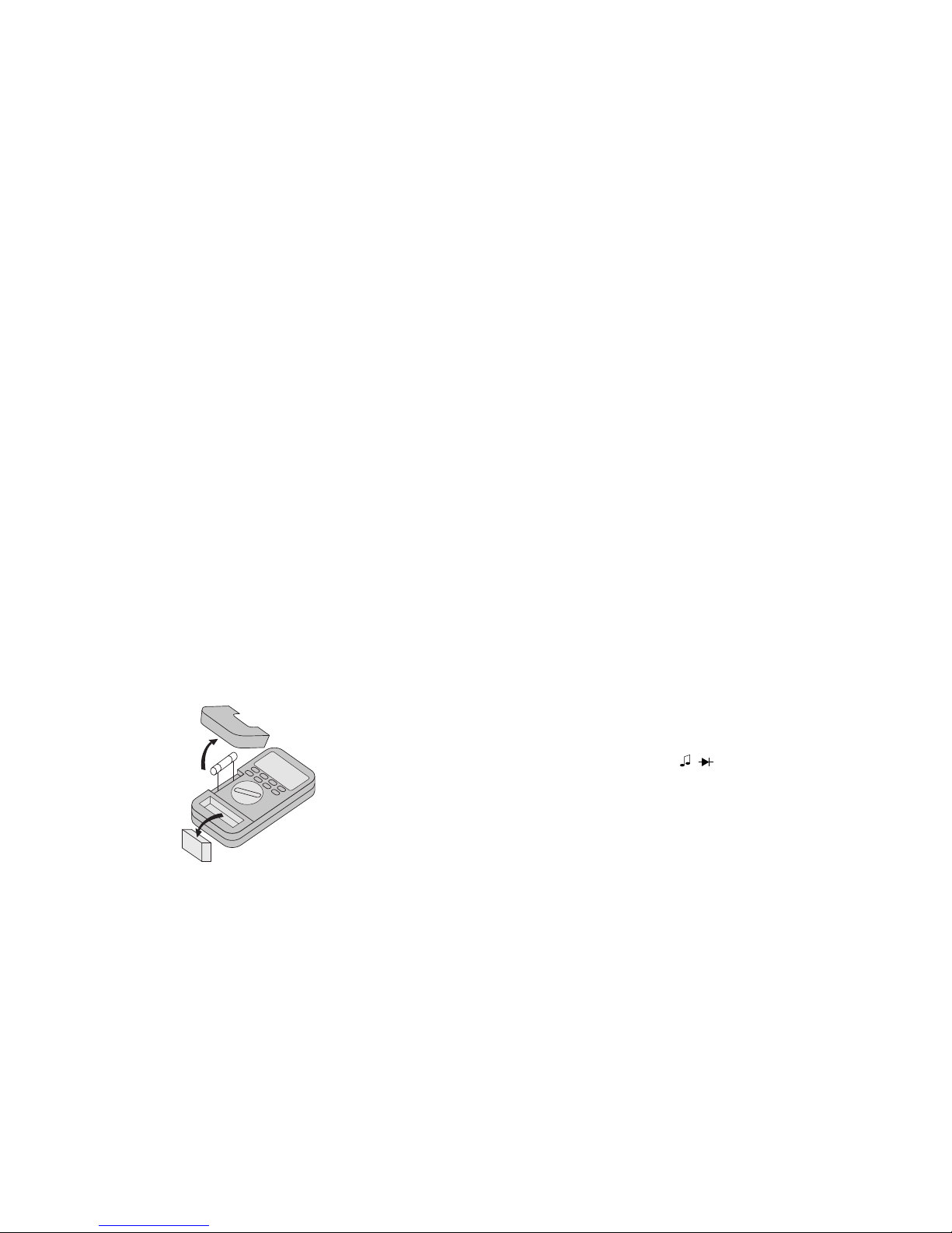
55
Attention!
Ne faites jamais fonctionner le multimètre alors qu'il est ouvert!
Danger de mort! Ne laissez pas de piles usagées dans le
multimètre car elles pourraient engendrer une corrosion qui
pourrait avoir des conséquences néfastes pour votre santé, en
raison des substances chimiques émises ou qui pourrait détruire
le boîtier de la pile. Vous devez traiter les piles usagées comme
des détritus à caractère spécial à éliminer conformément aux
règles de la protection de l'environnement. V ous devez jeter vos
batteries usagées selon les normes en vigueur auprès des
services de collecte (commerçant ou institution de récupération).
5.1.2 Test des fusibles
Avertissement
L'appareil de mesure possède deux fusibles: un fusible de
800 mA pour les valeurs de courant à mesurer jusqu'à 400 mA
maximum et un fusible de 20 A pour les valeurs de courant à
mesurer de 20 A maximum. Ces deux fusibles sont des fusibles
rapides. Le remplacement des fusibles est décrit au paragraphe
«3. Mesures de sécurité.
Une fonction spéciale de l'appareil de mesure permet avant
chaque mesure de vérifier l'état de fonctionnement et l'intégrité
des fusibles (indication: «fondu» ou «en bon état»). Procédez
comme suit et respectez les tableaux suivants:
- Réglez le commutateur « / » (= vérification de la connexion ou tests des diodes)
- Appuyez une fois sur la touche jaune. Le mot «FUSE» (= fusi ble) est affiché.
- Ne reliez «que» le câble rouge avec la prise V/Ohm/F du multimètre.
54
5. Utilisation du multimètre
5.1Installation de la batterie - Changement de la pile
et test des fusibles
5.1.1 Comment installer et remplacer la pile
Pour un fonctionnement optimal de votre appareil, utilisez des
piles de 9-V . Dès l'apparition du symbole de la pile à l'écran, vous
devez remplacer votre pile. Voici comment procéder:
Débranchez l'appareil de mesure du circuit électrique, écartez les
canaux de mesure de l'appareil de mesure, éteignez-le, retirez la
pochette de caoutchouc (si vous en possédez une) et défaites les
2 vis de fixation situées sur la partie inférieure du boîtier au
moyen d'un tournevis adéquat. Dégagez la protection de la prise
avec précaution (en utilisant éventuellement un petit tournevis ).
Consultez le tableau suivant. Détachez la pile usagée de la patte
de fixation et procédez au remplacement de la pile en mettant
une pile neuve du même type. N'oubliez pas non plus de
remettre la batterie dans son enveloppe.
Après cela, déposez la pile neuve dans le boîtier en la reliant.
Faites attention à ne pas coincer les conduits des griffes de
raccordement.
9V Batterie
Fusible
20 A 250 V
Page 29

57
5.3 Montage correct de l'appareil de mesure (couché à l'oblique)
ou position pour l'emploi. Manipulez le multimètre de sorte
que vous puissiez toujours lire l'affichage sur l'écran à cristaux
liquides (abréviation anglaise: écran LCD) ou que l'affichage
numérique soit tourné vers le haut. Afin de pouvoir mieux lire
l'affichage quand l'appareil est debout et pour que l'appareil
reste fixe, vous trouverez un pied rabattable sur le côté de
l'appareil.
5.4 Mise en service
5.4.1 Configuration de base
En plaçant le commutateur rotatif sur la fonction de mesure
voulue, branchez l'appareil de mesure. Vous pouvez maintenant
pratiquer des mesures «normales» sans vous servir des fonctions
supplémentaires.
Si vous souhaitez utiliser l'une des fonctions supplémentaire,
utilisez la touche à cet usage.
5.4.2 Répartition des fonctions sur le socle ou répartition des
prise ou bien marquage de l'interrupteur
a)Socle pour la mesure de capacités ou de température (polarités
«+» et «-»)
Branchez le condensateur déchargé dans sa prise en respectant
les polarités. Vérifiez que les câbles font la longueur suffisante, sinon vous risquez des erreurs de mesure.
Pour effectuer la mesure de températures, branchez un capteur thermométrique de type K (NiCrNi) en respectant le sens
des pôles dans la prise marquée à cet effet.
b)Commutateur des modes de fonctionnement = Commutateur
des fonctions de mesure (10)
56
- Touchez au moyen de la pointe de contrôle la partie métallique sur laquelle est installée la prise uA/ mA (tout en bas). Si
vous entendez un signal acoustique et que l'affichage graphique indique une hauteur minimum, le fusible est en état
de marche (800 mA, rapide). Si non le fusible ne fonc-tionne
plus. Vous devez donc le remplacer dans ce cas.
- Touchez, pour finir , au moyen de la pointe de contrôle la partie métallique sur laquelle est installée la prise A (tout en
bas). Si vous entendez un signal acoustique et que l'affichage graphique indique une hauteur minimum, le fusible est en
état de marche (20 A, rapide). Si non le fusible ne fonctionne
plus. Vous devez donc le remplacer dans ce cas.
5.2 Comment relier les câbles de mesure
Pour toutes vos mesures, utilisez exclusivement les câbles livrés
avec l'appareil de mesure. Contrôlez, avant chaque branchement, le bon état des éléments de branchement et des broches
de mesure et vérifiez la qualité de l'isolation. Ces câbles de
mesure sont normalisés pour soutenir des tensions de 1500 V
maximum. Votre appareil de mesure, le VC 350E, est conçu pour
résister à des tensions qui atteignent au maximum 1000 VDC ou
750 VACrms. Agissez avec la plus grande prudence quand vous
cherchez à mesurer des tensions supérieures à 25 V pour le
courant alternatif (AC) ou supérieures à 35 V pour le courant
continu (DC).
Attention!
Ne dépassez jamais les valeurs maximales de mesure, car, outre
le risque d'endommager votre appareil, vous courez un danger
de mort.
Page 30

59
uA = Mesure uA AC/DC (u = micro = exp 6), réglage
automatique et sélection manuelle de catégorie
(R-H) disponibles
mA/TEMP°C = Mesure mA AC/DC ou mesure de la température
en °C, réglage automatique et sélection manuelle
de catégorie (R-H) disponibles; par la touche
jaune, passage à la mesure de la température
A/TEMP°F = Mesure de courant continu et alternatif jusqu'à
20 A maximum, mesure de la température en °F,
réglage automatique et sélection manuelle de
catégorie (R-H) disponibles ; par la touche jaune,
passage à la mesure de la température
c) 2Prise 20A
Ficher ici le câble de mesure rouge pour des mesures de courant
continu ou alternatif jusqu'à 20 A.
Attention!
Quand vous mesurez des flux de courant, le commutateur des
fonctions de mesure ne doit surtout pas être réglé sur les
fonctions de mesure des tensions (mV ou V).
d) Prise mA
Ficher ici le câble de mesure rouge pour des mesures de courant continu ou alternatif jusqu'à 400 mA; mais seulement si
le mode de fonctionnement a été réglé sur la position «4mA»
ou «400mA».
e) COM = Prise commune
Pour toutes les mesures sauf pour les mesures de capacité ou
de température, vous devez ficher ici le câble de mesure
(Prise commune signifie prise moins ou «-» pour la masse)
58
Attention!
Ne jamais commuter le commutateur des modes de fonctionnement en cours de mesure, pour éviter de détruire l'appareil de
mesure et de vous mettre vous-même en danger de mort.
Présentées dans le sens de la rotation, voici les différents modes
de mesure que vous pouvez sélectionner en tournant le
commutateur:
OFF = A la fin de chaque mesure, débranchez l'appareil
de mesure
V = Volt AC/DC Pour cette catégorie de mesure, vous
pouvez sélectionner manuellement la catégorie
ou avoir recours au réglage automatique (R-H)
mV DC = millivolt DC (milli = 10 exp. 3) seulement un mV.
Echelle de mesure de tension de courant continu
jusqu'à 400 mV maximum
Ohm = Catégorie de mesure d'une résistance: on peut y
utiliser aussi bien le réglage automatique que la
sélection manuelle de catégorie (R-H)
«
/
» = Contrôle du fonctionnement/Test des diodes - pas
de réglage automatique ni de sélection manuelle
de catégorie possibles, pour passer à la fonction
voulue, appuyer sur la touche «bleue» FREQ =
Mesure de la fréquence; impossible de sélectionner manuellement la catégorie (avec R-H)
CAP = Mesure de la capacité- on peut y utiliser aussi bien
le réglage automatique que la sélection manuelle
de catégorie (R-H)
Page 31

61
- Fixer la catégorie dans laquelle doit être pratiquée la mesure
de la valeur de référence; appuyer pour cela sur la touche
«R-H» jusqu'à ce que la catégorie souhaitée soit indiquée.
- Mesurez, par exemple, dans la catégorie des mesures de tension une tension DC (pour une pile) de 1,5 V. Appuyer (tout en
faisant ces mesures) la touche «REL». La valeur de référence
(1,5 V) est maintenant installée. Effectuez vos mesures de tension en fonction de cette valeur de référence. Le résultat actuel de la mesure de l'objet à mesurer est représenté sur le petit
écran, tandis que sur l'écran principal s'affiche la diffé-rence
entre la mesure de référence configurée et cette mesure actuelle.
- Dès que vous éloignez les pointes de mesure de l'objet à mesurer , l'afficheur retourne à «0000» et la valeur de référence configurée est affichée sur l'écran principal.
D) COMP (= Comparaison)
Cette sous-fonction vous autorise à faire une comparaison entre
valeur supérieure et inférieure, alors que vous mesurez les
valeurs de référence supérieure et inférieure enregistrées avec le
résultat de la mesure actuelle.
Sur l'écran principal (grand afficheur), vous pouvez alors lire
l'indication «Lo» si la valeur du résultat actuel est plus petite que
la valeur de référence inférieure enregistrée au préalable. Vous
lirez au contraire «Hi» si la valeur du résultat actuel est plus
élevée que la valeur de référence supérieure enregistrée. C'est
l'indication «Pass» que l'on peut lire si la valeur du résultat actuel
est située entre les valeurs de référence supérieure et inférieure
enregistrées. Le résultat actuel est montré sur le petit écran.
Cette fonction ne peut pas être employée lors d'une mesure de
fréquence ou de capacité et de température. Pour sélectionner
cette fonction, procédez comme suit. Vous disposez de deux
méthodes pour entrer les valeurs de comparaison ou pour les
configurer.
60
f) Prise V/Ohm
C'est cette prise qui accueille le câble rouge de mesure,
quand vous effectuez des mesures de tensions ou de fréquences, des vérifications ou tests de diodes, de résistances
ou de logique.
5.4.3 Signification des symboles et signes de l'écran d'affichage
A) Affichage analogique
L'affichage à l'écran peut aller jusqu'au chiffre "4000", avec une
indication automatique de la polarité (signe: (-) pour des tensions négatives ou pour des polarités interverties). L'écran affiche
jusqu'à trois chiffres après la virgule.
B) Affichage graphique analogique
L'affichage graphique analogique est constitué de 43 segments.
Vitesse de mesure plus élevée que celle de l'afficheur numérique.
Mais il permet aussi de mieux visualiser des tendances de valeurs
mesurées, comme le ferait un multimètre analogique mais sans
ses désavantages mécaniques (comme le risque de condensation
du dispositif de mesure).
Si les valeurs de mesure sont saturées, l'indication "OL" (pour
Overload = saturation) s'affiche.
C) REL (= Relatif)
Par cette fonction, vous réalisez des mesures de référence; votre
«petit» afficheur vous indique la mesure actuellement en cours,
tandis que le grand afficheur vous donne la mesure de la différence. Fonction non disponible pour la meure de la fréquence, le
test des diodes, la vérification du fonctionnement et la mesure
de la température. En outre, pour les mesures en mode «REL»,
vous devez quitter le mode de réglage automatique et passer en
mode de sélection manuelle de la catégorie («R-H»). Pour installer une valeur de référence, pratiquez comme suit:
Page 32

63
alors que sur le petit écran d'affichage on peut lire «0000».
Pour mesurer une résistance, tester une diode ou contrôler
le fonctionnement, «Hi» apparaît sur l'écran principal au lieu
de «Lo». Sur le petit écran, c'est «OL» qui est indiqué (signifiant «Overload» en anglais, c'est-à-dire «surcharge» ou
saturation) au lieu de «0000».
D7) Reliez les pointes de contrôle avec l'objet sur lequel les
mesures de comparaison doivent être faites. Si la valeur
actuelle de la mesure qui est représentée sur le petit écran
est inférieure à la valeur de mesure la plus basse enregistrée,
vous verrez s'afficher «Lo» sur l'écran principal. Si la valeur
actuelle de la mesure est supérieure à la valeur de mesure la
plus haute enregistrée, vous verrez s'afficher «Hi» sur l'écran
principal. Si cette valeur actuelleest située entre les valeurs
de comparaison supérieure et inférieure enregistrées, vous
verrez apparaître l'indication «Pass» sur l'écran d'affichage
principal.
D8) Pour quitter la fonction, il faut d'abord débrancher l'appa-
reil de mesure du circuit électrique et ensuite tourner le
commutateur rotatif en avant d'une position.
Avertissement
On ne peut pas régler des valeurs négatives.
Méthode N° 2:
D1) Procédez comme indiqué pour D1) et D2) dans la possibilité
N° 1. Touchez ensuite avec les pointes de contrôle l'objet à
mesurer dont la valeur doit être configurée pour représenter
la limite supérieure (Hi).
Appuyez sur la touche « REL» jusqu'à ce que la valeur souhaitée apparaisse sur l'écran d'affichage principal. Pour cela,
l'unité numérique la plus à droite se met à clignoter. Eloig-
62
Méthode N° 1:
D1) Comme dans le cas de la mesure de la valeur de référence,
vous devez d'abord fixer la catégorie dans laquelle doit être
pratiquée la mesure de comparaison. Appuyez tout d'abord
sur la touche «R-H» jusqu'à ce que la catégorie souhaitée
soit installée.
D2) Ensuite, appuyez sur la touche «COMP» jusqu'à ce que clig-
note l'espace d'affichage numérique de l'écran principal.
Appuyez alors brièvement sur la touche pour faire apparaître sur l'écran, au lieu du mode de réglage , l'indication
«Err» signifiant «erreur». Le petit écran d'affichage vous
indique «Hi» (pour High = haut = valeur de comparaison
supérieure).
D3) Réglez maintenant à l'aide des touches « REL» et « R-H»
la valeur limite supérieure souhaitée pour cet espace d'affichage numérique. Pour finir, appuyez à nouveau sur la touche «COMP».
D4) La position numérique suivante (vers la gauche) clignote.
Procédez selon la description de c) jusqu'à ce que la valeur
de comparaison complète «Hi» soit configurée.
D5) Appuyez une nouvelle fois, pour finir , sur la touche «COMP».
La valeur supérieure «Hi» est fixé en mémoire et l'indication
«Hi» disparaît du petit écran pour être remplacée par l'indication «Lo» ( signifiant «Low» en anglais = bas = valeur de
comparaison inférieure ou valeur limite inférieure. A nouveau, l'espace d'affichage numérique de droite se met à clignoter.
D6) Configurez la valeur limite inférieure comme cela est décrit
sous c). Pour finir, appuyez sur la touche «COMP» une nouvelle fois. C'est ainsi que démarre la mesure de comparaison
. Sans qu'aucun signal ne l'annonce, «Lo» se trouve affiché
Page 33

65
E) MEM (= Memory = «enregistrement») et RCLL (= Recall
= «restitution»)
Cette fonction spéciale vous autorise à mémoriser jusqu'à
8 résultats de mesure (valeurs de référence) sauf pour les
mesures de température afin de les rappeler et de les restituer . Vous pouvez aussi enregistrer des résultats de fonctions
de mesure de différents types, comme la tension de courant
continu dans la mémoire 1, la résistance dans la mémoire 2
etc.. Procédez comme suit:
E1) Procédez à vos mesures. Si une valeur précise doit être enre-
gistrée, pour chaque enregistrement appuyez sur la touche
«MEM» quel que soit le type de mesure (à l'exception des
mesures de température. Deux chiffres, séparés par un espace blanc, arrivent à l'affichage sur le petit écran. A gauche,
la capacité de mémoire est indiquées, pour être directement
restituée («0» n'ayant pas encore été annoncé avec la touche
«RCLL»). A droite, sont indiqués les espaces de mémoire disponibles qui vont être utilisés ou décrits.
E2) En appuyant sur la touche «MEM», quand vous avez enregi-
stré la première valeur de mesure, la mémorisation est confirmée par l'apparition du signe «1». Vous pouvez ainsi conserver jusqu'à 8 résultats de mesure. Le chiffre 8 s'affiche sur
le petit écran, quand vous avez rempli tous les espaces de
mémoire disponibles.
E3) Si vous avez besoin d'un des 8 résultats enregistrés, vous
devez appuyer sur la touche «RCLL». Par chaque pression sur
cette touche «RCLL», vous ouvrez la mémoire la plus proche.
La valeur de mesure enregistrée est sélectionnée. L'espace
de mémoire sélectionné est indiqué à gauche par un chiffre
entre 1 et 8.
E4) Pour abandonner la fonction enregistrement/restitution sans
perdre les valeurs enregistrées, tournez le commutateur
rotatif (pas sur la position OFF). Pour effacer les valeurs enre-
64
nez maintenant les pointes de contrôle de l'objet à mesurer.
Appuyez 4 fois de suite sur la touche «COMP» jusqu'à ce que
l'indication «Hi» disparaisse du petit écran d'affichage et soit
remplacée par «Lo».
D2) Reliez les pointes de contrôle avec un nouvel objet à mesu-
rer, au moyen duquel vous souhaitez déterminer la valeur
limite inférieure (Lo). Appuyez maintenant sur la touche «
R-H» jusqu'à ce que la valeur souhaitée soit affichée sur
l'écran d'affichage principal. Le signe numérique le plus à
droite se met alors à clignoter. Eloignez les pointes de contrôle du (second) objet à mesurer . Appuyez 4 fois de suite sur
la touche «COMP» jusqu'à ce que l'indication «Lo» disparaisse du petit écran d'affichage et que la mesure de comparaison démarre. Sans indication d'autre signal de mesure, «Lo»
est affiché et la valeur «0000» apparaît sur le petit écran
d'affichage. Lors de mesures de résistances, de tests de
diodes et de contrôles de branchement électrique, c'est l'indication «Hi» qui apparaît sur l'écran principal d'affichage.
Et «OL» (pour «Overload»= surcharge) remplace «0000» sur
le petit écran.
D3) Reliez par les pointes de mesure l'objet sur lequel la mesure
de comparaison doit être effectuée. Si la valeur actuelle,
affichée sur le petit écran, est inférieure à la valeur de comparaison inférieure enregistrée, c'est «Lo» qui s'affiche sur
l'écran principal. Si la valeur actuelle est supérieure à la
valeur de comparaison supérieure enregistrée, «Hi» est
affiché sur l'écran principal. Si cette valeur mesurée se situe
entre les valeurs de comparaison inférieure et supérieure
enregistrées, «Pass» apparaît alors sur l'écran principal.
D4) Afin d'être en mesure de quitter la fonction, vous devez d'a-
bord séparer l'appareil de mesure du secteur et avancer le
commutateur rotatif d'une position.
Page 34

67
pour activer cette fonction spéciale. Dès que vous changez
manuellement de catégorie de mesure au cours des mesures,
vous quittez cette fonction spéciale. Pour l'installation / la
sélection de la fonction spéciale procédez de la façon suivante:
G1) Reliez le câble de mesure rouge avec la prise de mesure
appropriée à la fonction choisie (à l'exception de «COM»)
avec laquelle la fonction «Auto-Hold-MIN-MAX» sera appliquée. Reliez le câble de mesure noir avec la prise COM.
G2) Tournez le commutateur rotatif sur la fonction de mesure
souhaitée.
G3) Débranchez la fonction automatique «Auto-Range», en
réglant la catégorie de mesure manuellement à l'aide de la
touche «R-H».
G4) Si vous souhaitez travailler avec la fonction «Auto-Hold»,
appuyez sur la touche «REC». Ensuite le symbole «A-H»
apparaît dans le titre de l'affichage. Sur le petit et sur le
grand écran d'affichage, l'indication «0000» s'affiche, en
rapport avec le réglage de la catégorie. Pour les fonctions de
test de diodes , de mesure de résistance ou de contrôle de
circulation électrique au lieu de «0000» c'est «OL» (pour
«surcharge») qui s'affiche sur le «grand» écran d'affichage.
Reliez les pointes de contrôle avec le branchement de mesure. La valeur mesurée actuelle apparaît aussi bien sur le petit
que sur le grand écran d'affichage. Ecartez maintenant les
pointes de contrôle de l'objet à mesurer. Sur le grand écran,
il ne reste que la dernière mesure («gelée»/maintenue).
«OL» s'affiche sur le petit écran pour une mesure de résistance, un contrôle de circulation électrique ou un test de
diode. L'indication «0000» s'affiche sur le petit écran pour
toutes les autres fonctions de mesure.
Si vous démarrez maintenant une nouvelle opération de
66
gistrées, appuyez sur la touche «MEM» ou bien tournez le
commutateur rotatif sur «OFF».
Avertissement
Les valeurs mesurées, indépendamment de la configuration des
fonctions de mesure , sont restituées telles qu'elles ont été
enregistrées (par exemple, valeurs de tension en «V» pour les
mesures de résistance).
F) R-H (= Range Hold)
Dans cette fonction, vous pouvez arrêter la sélection automatique
de catégorie (Auto Range) et régler les catégories de mesure
manuellement. A la première pression sur la touche, le symbole
«AUTO» disparaît de l'écran d'affichage. A chaque nouvelle pres-
sion sur la touche « R-H», la décimale «se déplace» d'une position ou bien vers la gauche ou vers la droite; l'unité de mesure est
modifiée en conséquence.
Pour quitter cette fonction, appuyez sur la touche « R-H» jusqu'à ce que le symbole «AUTO» réapparaisse sur la barre
d'affichage du haut.
G)Auto Hold - Fonction MIN / MAX
La fonction de maintien automatique «Auto-Hold» permet de
«geler» / retenir un valeur mesurée pour un usage postérieur
comme, par exemple, pour un procès-verbal de mesure. La
fonction MIN enregistre automatiquement la valeur la plus
petite d'une mesure. La fonction MAX enregistre
automatiquement la plus haute valeur mesurée. Cette (ces)
fonction(s) spéciale(s) n'est pas (ne sont pas) disponible(s) pour
les mesures de température, de capacité ou de fréquence.
Pendant que l'on emploie une de ces fonctions spéciales, le mode
«Auto-Range» (sélection de catégorie automatique) n'est plus
sélectionné.
D'où vous devez configurer une catégorie de mesure précise
Page 35

69
sur le petit écran. La valeur mesurée sur le grand écran d'affichage reste aussi longtemps affichée qu'une nou-velle
mesure de plus petite valeur soit enregistrée. Le grand afficheur indique toujours la plus petite valeur mesurée.
G6) Si vous souhaitez utiliser la fonction «MAX» et que vous vous
trouviez en train de travailler avec la fonction «MIN», appuyez sur la touche «REC» une nouvelle fois. Le symbole «MIN»
disparaît et le symbole «MAX» le remplace sur le côté gauche. Si vous êtes justement en mode «Auto-Hold», vous
devez appuyer deux fois de suite sur la touche «REC». Si le
mode «Auto-Hold» n'a pas été sélectionné, vous devez
appuyer trois fois de suite sur la touche «REC».
Avertissement
Le processus de mesure en mode «MAX» est identique au
processus de mesure en mode «MIN». Procédez donc comme
indiqué dans le mode d'emploi de la fonction de mesure
«MIN».
Reliez maintenant les pointes de contrôle avec le branchement à
mesurer (l'objet à mesurer). La valeur actuelle du résultat
apparaît aussi bien sur le grand écran que sur le petit. Eloignez
les pointes de contrôle de l'objet à mesurer. La dernière valeur
mesurée este «stable» sur le grand écran d'affichage (maintenue). L'indication «OL» s'affiche sur le petit écran pour les
mesures de résistance, les contrôles de circulation électrique et le
test de diodes. Pour les autres fonctions de mesure, c'est
l'indication «0000» qui s'affiche sur le petit écran. La valeur
mesurée sur le grand écran d'affichage reste aussi longtemps
affichée qu'une nouvelle mesure de plus grande valeur soit
enregistrée. Le grand afficheur indique toujours la plus grande
valeur mesurée.
68
mesure, le résultat affiché précédemment demeure encore
affiché environ 4 minutes sur le grand écran avant de disparaître et de laisser le place à la nouvelle valeur mesurée.
G5) Si vous voulez travailler avec la fonction MIN, alors que vous
êtes encore en train d'activer la fonction «Auto-Hold»,
appuyez sur la touche «REC» une nouvelle fois. Le symbole
«A-H» pour «Auto-Hold» disparaît de la barre de titre et est
remplacé par le symbole «MIN». Si cependant vous êtes en
train de travailler en mode «MAX» ou que vous ne vous
trouvez pas en mode «Auto-Hold», vous devez réappuyer sur
la touche REC deux fois de suite.
Avertissement
Afin de rendre possible une mesure en mode «MIN» quand vous
êtes en train de faire une mesure de résistance, un test de diode
ou un contrôle de circulation électrique, vous devez soit mettre
l'une contre l'autre (en «court-circuit») les pointes de contrôle ou
mesurer une valeur de résistance. A partir de là, vous pourrez
appuyer sur la touche «REC»: le symbole «A-H» disparaîtra de
l'écran d'affichage pour être remplacé par le symbole «MIN».
Dès que vous lisez l'indication «MIN», vous êtes libre de procéder à vos mesures (mesure de résistance, test de diode ou
contrôle de circulation électrique). Cette «procédure» n'est pas
indispensable pour toutes les autres mesures.
Reliez maintenant les pointes de contrôle avec le branchement à mesurer (l'objet à mesurer). La valeur actuelle du
résultat apparaît aussi bien sur le grand écran que sur le
petit. Eloignez les pointes de contrôlede l'objet à mesurer . La
dernière valeur mesurée este «stable» sur le grand écran
d'affichage (maintenue). L'indication «OL» s'affiche sur le
petit écran pour les mesures de résistance, les contrôles de
circulation électrique et le test de diodes. Pour les autres
fonctions de mesure, c'est l'indication «0000» qui s'affiche
Page 36

71
H3) Pour débrancher la fonction «Auto-Power-Off» (débranche-
ment automatique), vous devez, avant le branchement de
l'appareil (au moyen du commutateur rotatif) appuyer sur la
touche bleue. Relâchez la touche bleue au bout de 2 à
3 secondes seulement et branchez tout de suite l'appareil de
mesure au moyen du commutateur rotatif. L'appareil de
mesure se débranchera au bout d'environ 13 minutes mais il
restera en état de fonctionner aussi longtemps que la batterie sera active ou tant que vous n'aurez pas tourné le commutateur rotatif sur la position «OFF» (arrêt de l'appareil). Si
vous éteignez l'appareil de mesure à partir du commutateur
rotatif et que vous le rebranchiez aussitôt après, vous réactivez la fonction «Auto-Power-Off» (débranchement automatique), ce qui signifie que l'appareil de mesure se débranchera automatiquement au bout d'environ 13 minutes.
5.4.4 Indications de l'affichage ou symboles des modes de fonc-
tionnement
a) Affichage du changement de pile
La pile de 9-V a une autonomie d'environ 400 à 150 heures.
«A peu près 8 heures avant la fin de la pile, apparaît à l'écran
le symbole pour annoncer le remplacement de la pile». Entre
les singles cycles de mésure chaque fois un contrôle de la batterie sera effectué.
b) tous les autres symboles, correspondant à différentes unités
de mesure:
AC = Valeur alternative
DC = Valeur continue
mV = Millivolt (exp -3)
V = Volt
uA = Micro-Ampère (exp -6)
+
-
70
H) Fonctions spéciales de «mise en marche de l'appareil»
Quand vous branchez l'appareil, diverses fonctions spéciales sont
«déclenchées». La «mesure de fréquence» pour le courant
alternatif ou la mesure de tension de courant alternatif de 50 Hz à
60 Hz et inversement sont configurées. Il est aussi possible de
connecter une imprimante en série et de sélectionner le port
d'imprimante à partir de la fonction «mise en marche de
l'appareil». Avec la dernière des trois fonctions spéciales de
«mise en marche de l'appareil», vous pouvez débrancher la
fonction «Auto-Power-Off» (débranchement automatique au
bout d'environ 13 minutes). Pour sélectionner une de ces
fonctions spéciales, procédez comme suit:
H1) Pour changer la mesure de la fréquence, vous devez tenir
enfoncée la touche jaune lors du branchement de l'appareil
de mesure (au-dessus du commutateur rotatif) et le relâcher
seulement au bout de 2 à 3 secondes. Sur cela s'affiche à
l'écran, en fonction du réglage précédent, l'indication
«50 Hz» ou «60 Hz». Pour pratiquer une configuration/
modification sur la nouvelle valeur trouvée à chaque mesu-
re, il faut utiliser les touches « REL» ou « R-H». Après configuration, appuyez à nouveau sur la touche jaune. Un signal acoustique retentit en signe de confirmation.
H2) Pour sélectionner le port d'imprimante (branchement), vous
devez, avant le branchement de l'appareil de mesure (par le
commutateur rotatif), appuyer sur la touche «REC» et sur la
touche jaune. Relâchez la touche jaune au bout de 2 à
3 secondes seulement, tout en maintenant la touche «REC»
encore appuyée. Vous pouvez brancher l'appareil de mesure
tout de suite. Le port d'imprimante est sélectionné. Toutes les
dix secondes, par l'intermédiaire de l'imprimante en série qui
est connectée à l'appareil de mesure, les résultats de la mesure, avec la valeur de la mesure, la catégorie et l'unité de
mesure, sont imprimés. Pour débrancher le port d'imprimante, tournez le commutateur rotatif sur la position «OFF».
Page 37

73
6. Réalisation de mesures
Généralités:
Le multimètre n'est pas protégé au cas où les câbles de mesure
seraient connectés aux mauvaises prises de mesure en rapport
avec les différentes fonctions de mesure. Il peut être
endommagé ou même détruit.
Pour éviter ce risque, le multimètre est équipé d'un système
d'alarme acoustique en relation avec les prises, qui, en relation
avec les différentes fonctions de mesure (mode V, Fréquence,
Ohm ou Capacité etc.) Donne divers signaux pour prévenir. Que
le câble de mesure rouge, par exemple soit fiché dans une des
prises de mesure de courant (uA/mA ou A) et que le câble de
mesure noir soit connecté avec la prise COM alors que le
commutateur rotatifn'est pas en position de mesurer le courant,
vous entendrez les signaux acoustiques suivants:
V AC/DC : ——————— (signal continu)
mV DC/FREQ : - - - - - - - - (signal intermittent «lent»)
Ohm / /->l- : - - - - - - - - - - - (signal intermittent «rapide»)
CAP : (aucun signal sonore)
Avertissement
Si vous employez d'autres câbles de mesure que ceux qui sont
livrés avec l'appareil, aucun signal acoustique n'est disponible.
6.1 Mesure des tensions
Attention!
En aucun cas, vous ne devez dépasser les valeurs d'entrée maximales. Valeur maximale: 1000 VDC ou 750 VACrms.
Ne touchez aucun branchement ou corps de branchement, si
vous souhaitez mesurer des tensions supérieures à 25 VACrms
72
mA = Milliampère (exp -3)
A = Ampère
kHz = Kilohertz (exp 3)
MHz = Mégahertz (exp 6)
°C = Degré Celsius
°F = Degré Fahrenheit
uF = Microfarad (exp -6)
nF = Nanofarad (exp -9)
kΩ = Kiloohm (exp 3)
MΩ = Mégaohm (exp 6)
5.5 Recherche d'erreur
Si votre multimètre ne fonctionne pas normalement, vous
pouvez identifier une des origines suivantes:
Suppression de l'origine de l'erreur
L’appareil de mesure Lisez le mode d'emploi attentivene fonctionne pas: ment.
Est-ce que la batterie est en état
de fonctionner?
La batterie est en bon Est-ce que le fusible est en état
état de marche, mais les de fonctionner?
fusibles fonctionnent-ils? Vérifiez le(s) fusible(s) conforme-
ment au paragraphe 5.1.2.
Est-ce que le(s) fusible(s) est (sont)
dans leur logement?
Page 38

75
parallèle à 100 pF). L'entrée de tension de courant alternatif est
connectée avec AC. Notez que dès qu'apparaît un signe "-"
devant la valeur mesurée, dans le cas de mesure de tensions de
courant continu, la valeur mesurée porte sur une tension négative (ou vos câbles de mesure ont été intervertis).
Avertissements
- L'entrée des mesures étant très sensible, il peut arriver que, si
les câbles de mesure sont libres (c'est-à-dire non reliés à un
objet à mesurer), des valeurs de mesure quelconques soient
indiquées. Un tel «phénomène» est normal et disparaît dès
que vous pratiquez des mesures.
- Dans la catégorie de mesure «mVDC», le mode «Auto-Range»
(sélection automatique de catégorie) n'est pas disponible.
6.2 Mesure du courant
Pour mesurer des flux de courant électrique continu ou alternatif, procédez comme suit:
1. Reliez le câble de mesure rouge à la prise V/Ω (10) et raccordez
le câble noir à la prise COM.
2. Placez le commutateur rotatif sur la mesure du courant (uA
maximum de 4000 uA, ou mA jusqu'à un maximum de 400 mA
ou bien A jusqu'à un maximum de 20 A). Dans la catégorie de
mesure de courant vous avez accès aussi bien à la sélection
automatique («Auto-Range») qu'à la sélection manuelle de
catégorie («R-H»).
3. Appuyez sur la touche bleue selon que vous voulez mesurer du
courant continu ou alternatif. Dès que l'indication «AC» est
affichée, vous vous trouvez dans la catégorie de mesure du
courant alternatif.
4. «Détachez» le branchement de mesure hors tension (objet à
mesurer débranché) et reliez le(s) câble(s) de mesure en série
74
ou à 35 VDC.
Cet appareil de mesure ne peut être utilisé qu'avec des installations de la catégorie II de surtension.
Pour mesurer des tensions de courant continu ou alternatif,
procédez comme suit:
1. Reliez le câble de mesure rouge à la prise V/Ω (10) et raccordez
le câble noir à la prise COM (9).
2. Tournez le commutateur rotatif sur la position souhaitée (V)
ou sur «mVDC» au cas où vous ne mesurez que des tensions de
courant continu.
3. Appuyez sur la touche bleue selon que vous souhaitez mesurer
une tension de courant continu ou une tension de courant
alternatif (à l'exception de mVDC). Dès que l'écran affiche
«AC», vous vous trouvez dans la catégorie de mesure de tension de courant alternatif.
4. Raccordez les broches de mesure à l'objet à mesurer (charge,
branchement etc.).
Attention!
Comme les contacts de métal de la prise sont situés assez en
profondeur (pour des raisons de sécurité) il vous est fortement
recommandé d'enfoncer les fiches du câble de mesure à fond
dans la prise souhaitée. Assurez-vous bien du fait que les fiches
du câble de mesure sont bien connectées avec l'appareil de
mesure, avant de prendre pour correct un résultat de mesur e nul
(«0V»), et qu'elles touchent les parties de connexion. Attention!
Vous êtes en danger de mort si vous restez en contact avec des
tensions supérieures à 25 VACrms ou 35 VDC.
Chacune des catégories de tension (tension de courant alternatif
comme continu) a une résistance d'entrée de 10 MOhm (en
Page 39

77
1. Reliez le câble de mesure rouge à la prise V/Ω (10) et raccordez
le câble noir à la prise COM (9).
2. Tournez le commutateur rotatif en position / . Les sym-
boles suivants s'affichent à l'écran (espace d'affichage): «OL»,
« » et «Ω». Si ces symboles n'apparaissent pas, appu-yez sur
la touche bleue.
3. Enfin raccordez les broches de mesure avec l'objet à mesurer
qui doit absolument être hors tension.
En relation avec les résistances de tension en place, vous
entendrez les signaux acoustiques suivants:
————————— (signal continu) à 30 Ohm ou moins
— — — — — — — (signal intermittent «lent») pour une valeur
supérieure à 30 Ohm et inférieure à 106
Ohm
————- ———- (signal continu interrompu) pour une valeur
supérieure à 106 Ohm et inférieure à 1700
Ohm
Attention!
Ne mesurez jamais de condensateurs chargés, sinon vous
pouvez endommager votre appareil si le condensateur vient à se
décharger .
La valeur affichée ne représente pas la «vraie» valeur de
résistance. Pour la déterminer, vous devez pratiquer une mesure
de résistance (cf. suite).
76
avec l'objet à mesurer hors tension (cf. illustration ci-dessous).
5. Branchez la tension sur l'objet à mesurer (branchement, câble
etc.) et lisez la valeur mesurée pour le courant. Dès que vous
voyez un «-» devant la valeur mesurée, il s'agit d'une valeur de
courant continu, plus exactement d'une valeur négative ou
bien vos câbles de mesure sont mal connectés.
Attention!
Ne mesurez jamais du courant d'un circuit électrique avec des
tensions supérieures à 250 VDC ou VACrms: si non vous risquez
d'endommager le multimètre et vous serez même en danger de
mort. Vous ne devez jamais mesurer des courants supérieurs à
20 A. Ne pratiquez vos mesure que sur des circuits électriques
qui ont une protection par fusible de 16 A ou dans lesquels ne
peuvent jamais passer de tensions supérieures à 4000 VA.
Des mesures de courant électrique de 20 A ne doivent pas avoir
un période supérieur à 10s et ne doivent être effectuées qu'en
respectant des intervalles de 15 minutes entre chaque mesure
(temps de refroidissement de la dérivation).
6.3 Contrôle de la circulation électrique
Grâce à cette fonction, vous pouvez mesurer de façon acoustique
la connexion de câbles, fusibles, branchements etc.. Pour
pratiquer cette mesure, procédez comme suit:
A
DMM
Consommateur,
charge,
branchement
Source
électrique
Page 40

79
l'affichage graphique indique tous les segments, vous avez
dépassé les valeurs de mesure: la mesure se trouve alors
interrompue (> 40 MOhm).
6.5 Test de diodes
Pour mesurer des circuits semi-conducteurs (diodes, transistors,
redresseurs etc.), procédez comme suit:
1. Reliez le câble de mesure rouge à la prise V/Ω (10) et raccordez
le câble noir à la prise COM.
2. Positionnez le commutateur rotatif sur « / » et appuyez
une seule fois sur la touche bleue. Les symboles suivants sont mis
en évidence sur l'écran (zone d'affichage): Le symbole pour la
diode «->l-», «mV» et «OL» (pour surcharge ou ici: «valeur en
ohms infiniment élevée»). Une sélection manuelle n'est pas possible.
3. Reliez maintenant les pointes de contrôle avec l'objet à mesurer, un circuit semi-conducteur hors tension, en mettant la
pointe rouge en contact avec l'anode et la pointe noire avec la
cathode (celle-ci est d'habitude marquée par un anneau ou un
point de couleur).
Si vous contrôlez une diode ou une capacité, vous devrez vous
limiter à des valeurs de tension comprises entre environ 0,25 V
(Germanium) ou 0,7 V (Silicium) et 2,0 V (ou 250 mV, 700 mV
jusqu'à 2000 mV), au cas où la diode n'est pas défectueuse.
Si vous intervertissez alors les broches de contrôle, en mettant
la broche rouge à la cathode et la noire à l'anode, vous allez
contrôler ce qui s'appelle le sens de blocage de la diode.
Si "OL" s'affiche à l'écran, alors la diode est en bon état de
marche. Si vous voyez s'afficher une valeur comprise entre 0 V
et «OL», vous avez sûrement mal connecté l'objet à mesurer
ou celui-ci est en défectueux.
78
6.4 Mesure de résistance
Attention!
Assurez-vous que tous les branchements et éléments à mesurer
ainsi que tous les objets à mesurer sont absolument bien hors
tension.
Pour mesurer des résistances hors tension jusqu'à une valeur
maximale de 40 Mohm, procédez comme suit:
1. Reliez le câble de mesure rouge à la prise V/Ω (10) et raccordez
le câble noir à la prise COM.
2. Tournez le commutateur de fonctions de mesure sur la position de mesure de résistance (Ohm).
3. Enfin raccordez les broches de mesure avec l'objet à mesurer
qui doit absolument être hors tension. La sélection automatique («Auto Range») recherche toujours la catégorie la
plus appropriée, afin de ne produire éventuellement qu'une
erreur de mesure minimale.
La résistance des câbles de mesure est normalement très minime
et sans la moindre influence sur la mesure (environ 0,1 à 0,2
Ohm). Mais cette valeur même minime peut conduire à des
inexactitudes dans la mesure pour la catégorie des 400 Ohms.
Afin de compenser ces «erreurs de mesure», vous pouvez utiliser
la fonction «REL» (décrite sous 4.4.3.C).
Si vous pratiquez une mesure de résistance, vérifiez bien que les
points à mesurer, qui vont être touchés par les pointes de
mesure, ne sont pas recouverts de saleté, d'huile, d'huile de
soudure ou équivalent. Si non vos résultats pourraient être
influencés par ces interférences.
Dans le cas de résistances supérieures à 4 MOhms, il peut arriver
que l'afficheur ait besoin d'un peu plus de temps pour se
stabiliser. Dès que le signal "OL" s'affiche à l'écran et que
Page 41

81
Avertissement
Pour mener la mesure la plus précise possible, utilisez exclusivement un câble blindé (avec douille à baïonnette/BNC) (adaptateur disponible chez nous) afin d'écarter toute erreur de mesure
venant d'interférences de champs électriques interférence.
Il est impossible de se servir de la sélection manuelle pendant les
mesures de fréquence!
6.7 Mesure de capacité
Attention!
Si des courts-circuits de condensateurs se produisent, des
décharges d'énergie puissantes peuvent advenir . Attention: vous
êtes alors en danger de mort! Ne touchez jamais les connections
de condensateurs de tensions supérieures à 35 VDC ou 25 VAC.
Attention si vous vous trouvez dans des pièces où peuvent
dominer des poussières, des gaz inflammables, des vapeurs ou
des liquides. ==> Risque d'explosion!
Pour mesurer des capacités de condensateurs, procédez comme
suit:
1. Déchargez chaque condensateur, avant de le relier avec votre
appareil de mesure. Ne mesurez jamais de condensateurs chargés parce que cela pourrait endommager votre appareil de
mesure.
2. Positionnez le commutateur rotatif sur «CAP».
3. Les mesures (ne) peuvent être désormais menées (qu') avec un
socle de mesure installé sur l'appareil de mesure. N'oubliez pas
de vérifier si la polarité est correcte («+» et «-») quand vous
mesurez des condensateurs monopolaires. Vérifiez aussi que
les broches de raccordement («molles») sont assez longues et
pas trop fines. Si les raccordements sont trop courts ou font
80
La tension de contrôle pour un test de diode suffit aussi pour
provoquer «l'illumination» de la plupart des diodes électroluminescentes à bas courant (Low Current). Pour des tensions de
courant de diodes électroluminescentes supé-rieures à 2,0 V,
votre multimètre numérique peut parfois indiquer, de façon
erronée, que la diode est défectueuse.
Attention!
Veillez, lors de tests de diodes, à ce que la diode ou le
branchement qui l'abrite soit absolument hors tension. Toutes
les capacités doivent être déchargées.
6.6 Mesure de fréquence
Attention!
Respectez obligatoirement les valeurs d'entrée maximales! Ne
vous connectez jamais à des tensions supérieures à un maximum
de 250 VDC/VACrms (rms = effectifs). Au contact de tensions
supérieures à 25 VAC ou à 35 VDC, vous courez un danger de
mort.
Au cours des mesures de tensions de courant (supérieures à
25 VAC ou 35 VDC), vous ne devez jamais vous brancher sur une
autre fonction de mesure (= manipulation du commutateur
rotation). L'électronique ultrasensible contenue à l'intérieur de
l'appareil pourrait en être détruite et votre vie pourrait même
être aussi en danger.
Pour mesurer une fréquence, procédez comme suit:
1. Reliez le câble de mesure rouge à la prise V/Ω (10) et raccordez
le câble noir à la prise COM.
2. Positionnez le commutateur rotatif sur «FREQ».
3. Reliez les pointes de contrôle avec l'objet à mesurer (géné-
rateur ou autre).
Page 42

83
variables pour lesquels un affichage numérique s'avère trop
"lent". Vous pouvez ainsi facilement repérer les tendances
suivies par les modifications des valeurs mesurées.
6.11 Comment utiliser le multimètre en le reliant à
un ordinateur
Avec votre multimètre, vous disposez d'une disquette sur
laquelle se trouvent les logiciels de fonctionnement sous DOS et
le logiciel de fonctionnement sous Windows 95. Pour que votre
appareil de mesure puisse se connecter à votre ordinateur
(compatible IBM), vous devez d'abord installer le logiciel.
Avertissement
L'installation du programme suivante exige les connaissances de
base de divers ordres sous MS-DOS pour avoir accès à un disque
dur . Relisez attentivement votre manuel MS-DOS pour retrouver
le processus d'installation d'un logiciel, si vous avez oublié les
connaissances de base pour le maniement des consignes sous
MS-DOS. N'oubliez pas que vous avez aussi besoin d'un
moniteur VGA (équipé en outre d'une carte VGA).
Etape 1
1. Démarrez votre ordinateur et sélectionnez Windows. Win-
dows 95 est chargé automatiquement (en fonctionne-ment
normal).
2. Quand vous êtes dans la surface de travail de Windows,
introduisez la disquette dans le lecteur de disquette 3,5" (lecteur A ou B etc. selon l'installation).
3. Cliquez avec la touche gauche de votre souris sur la fenêtre
de démarrage (en bas à gauche dans la barre sur: «START»)
et cliquez ensuite sur «RUN» (ou «Exécuter»).
82
contact ou que le condensateur est défectueux, votre afficheur
annoncera une valeur de capacité d'environ 00,11 nF.
6.9 Mesure de la température
L'affichage de la température a une échelle qui va de -40°C à
+1000°C ou de -40°F à 2000°F, en relation avec le capteur de
mesure disponible en option. Cette mesure de température est
conduite exclusivement au moyen de capteurs thermométriques
de type K (NiCrNi). Tant que vous n'aurez pas relié le capteur de
température avec le socle de mesure de l'appareil de mesure,
c'est la température ambiante actuelle (température d'envi-ronnement) qui s'affiche en degrés C ou F. Pour mesurer des
températures, procédez comme suit:
1. Positionnez le commutateur des fonctions de mesure soit sur
«mA/TEMP°C» soit sur «A/TEMP°F» et appuyez une fois sur la
touche jaune.
2. Reliez la fiche de l'élément thermométrique en respectant la
polarité (étroite et large broches de contact) avec la prise de
mesure CAP/TEMP.
Attention!
Ne faites aucun branchement sous tension. Vous pourriez
endommager votre multimètre.
6.10 Comment utiliser l'affichage graphique
analogique
L'affichage graphique analogique est d'un usage aisé et
compréhensible. On peut le comparer avec l'afficheur d'un
instrument analogique qui serait dépourvu de ses défauts
mécaniques. Il convient particulièrement aux signaux de mesure
Page 43

85
Vitesse en Bauds 1200 (vitesse de transmission: 1200 signes à
la seconde)
d) Après avoir entré les données, cliquez sur «SAVE» pour
mémoriser en permanence ces données et, pour finir, cliquez
sur «CLOSE» pour fermer la fenêtre.
e) Pour conduire ce programme informatique, cliquez sur
«OFF», à droite dans la barre d'état de la boîte du menu.
Etape 3
Voici comment se présente l'utilisation du logiciel MS-DOS:
a) Connectez votre ordinateur à votre appareil de mesure. Le
programme MS-DOS est désigné par le titre de METRE.
Avertissement
L'installation du programme suivante exige les connaissances de
base de divers ordres sous MS-DOS pour avoir accès à un disque
dur . Relisez attentivement votre manuel MS-DOS pour retrouver
le processus d'installation d'un logiciel, si vous avez oublié les
connaissances de base pour le maniement des consignes sous
MS-DOS. N'oubliez pas que vous avez aussi besoin d'un
moniteur VGA (équipé en outre d'une carte VGA).
1. Introduisez la disquette dans le lecteur adéquat (A, B ou
autre).
2. Créez un répertoire sur votre disque dur (la plupart du temps
sur C) intitulé «METRE».
cd\ [Entrée]
md METRE [Entrée] [Entrée] = Appuyez sur la touche
«Entrée».
3. Passez au lecteur A (ou B ou autre selon l'installation de votre
ordinateur). Sélectionnez le fichier METRE et appuyez sur la
touche ENTREE. Par exemple:
84
4. Sur cela vous voyez s'afficher l'indication: «A:<\\>Setup.EXE».
Cliquez sur «OK». Suivez les indications à l'écran dans le programme de configuration.
5. Après avoir chargé avec succès le logiciel, cliquez avec la touche gauche de la souris sur «OK».
Etape 2
Le logiciel marchant sous Windows 95 a été chargé. Pour
«communiquer» maintenant avec le multimètre vous devez
effectuer les procédures (saisies) suivantes:
a)Reliez la fiche à 4 broches du câble d'interface (livré avec l'ap-
pareil) avec l'interface RS-232 sur l'appareil de mesure
(débranché). L'autre extrémité du câble d'interface doit être
connectée avec un port série libre (débranché) de votre ordinateur.
b) Branchez votre ordinateur. Ouvrez la fenêtre de démarrage
(START) sous Windows 95. Cliquez avec le pointeur de votre
souris et avec la touche gauche de votre souris sur le menu
PROGRAMME. Dans le dossierse trouve, entre autres, le titre
«DMM97». Cliquez sur ce titre «DMM97». Alors s'affiche la
mention suivante: «About Scope View» (ou «Au sujet de la vue
en scope»). Cliquez sur OK.
c) Le menu principal de vue en scope («Scope View Main Menu»)
est affiché. Pour configurer votre matériel informatique ou
pour modifier sa configuration, cliquez maintenant sur
«setup». Sur cela apparaît à l'écran le programme de configuration («setup») de «Scope View». Entrez les informations suivantes:
Modèle de mètre 350E (dénomination du modèle du
multimètre)
Port de Communication COM1 ou COM2 ou autre
(Interface de l'ordinateur)
Page 44

87
Transmission de données entre l'appareil de mesure et
l'ordinateur bidirectionnelle, c'est-à-dire dans les deux
directions.
7. Entretien et calibrage
Afin de garantir au multimètre une précision de mesure à long
terme , il conviendrait de le faire calibrer une fois par an (la
calibration est comprise dans le service 2000).
Changement de fusible cf. description en 3. (Mesures de sécurité)
cf. description. Le remplacement des piles est décrit au chapitre
5.1.1.
Afin de nettoyer l'appareil ou la fenêtre d'affichage, utilisez un
chiffon propre et sec (sans peluches) de type antistatique.
Attention!
N'utilisez pour le nettoyage aucun produit avec dérivés de
carbone ou contenant de l'alcool. La surface de l'adaptateur à
pince/des câbles de connexion pourrait être attaquée par cela.
En outre, leurs émanations nuisent à la santé et présentent un
risque d'explosion. N'utilisez jamais d'outils pointus et acérés
pour le nettoyage, comme des tournevis ou des brosses en
métal etc.
RXD
RS-232C
GND
TXD
DSR
RTS
86
cd METRE
4. Copiez les fichiers de votre disquette sur le disque dur:
copy a:\DOS c:
5. Pour démarrer votre programme, entrez «DMM» et appuyez
sur la touche d'entrée. Suivez ensuite les indications à l'écran.
Avertissements
Si vous ne disposez pas d'un disque dur, vous pouvez démarrer
le programme à partir de la disquette:
Passez au lecteur sur lequel est installée votre disquette. Passez
dans le dossier «DOS» à la disquette, entrez «DMM» et appuyez
sur la touche ENTREE.
Pour arrêter le programme ou si une «ERREUR» apparaît, faites
un «démarrage à chaud» (Touches Maj+Alt+Suppr).
Etape 4
Les paramètres de communication sont expliqués ici:
Vitesse de transmission : 1200 bauds
Code de caractères : ASCII 8 octets
Parité : aucune
Octet d'arrêt : 1
Etape 5
Voici comment se répartit la composition de l'interface de
l'appareil de mesure:
Page 45

89
Température pour une
précision garantie ................: +23°C ±5K
Affichage de
changement de batterie......: « » sera affiché
Type de batterie ...................: Type de piles: NEDA 1604 9V ou
6F22 9V (Alkaline)
Masse ....................................: 364 g (avec pile)
Dimensions
(Long. X Larg. X Haut.)......: 189 x 90 x 38 mm
8.2 Tolérances de mesure
Données de la précision en ± (% à la lecture des données +
nombre de positions = digits = dgt(s).
Précision garantie 1 année par une température idéale de +23°C
± 5°C, avec une humidité de l'air relative inférieure à 75 %, sans
condensation. Le temps de réchauffement avant usage est de:
1 minute
+
-
88
8. Caractéristiques techniques et tolérances
des mesures
8.1 Données techniques
Affichage (écran)..................: Ecran à cristaux liquides à 33/
4
positions affichant jusqu'à 4000
(3999), avec affichage automatique de la polarité
41/2positions pour la mesure de
fréquence
Petit écran d'affichage à 41/2positions
+ affichage graphique analogique
(Afficheur avec segments de barres)
Vitesse de mesure maximale: 2,5 mesures par seconde
Courant d'entrée
maximum AC/DC..................: 20 A
Résistance d'entrée..............: 10 MΩ en parallèle à 100pF (VDC
et VAC)
Affichage du dépassement..: «OL» pour Overload = Dépassement
de travail...............................: de 0°C à +40°C, avec une humidité
de l'air relative < de 75%, sans
condensation
Température de stockage ....: de -10°C à +50°C, avec une humi-
dité de l'air relative < de 75 %,
sans condensation, batterie non
installée
Page 46

91
8.3 Valeurs d'entrée maximales
Mesure de tension : 1000 VDC ou 750 VAC
Mesure de courant : 20 A AC/DC dans la catégorie A,
400mA AC/DC dans la catégorie A
Mesure de la résistance : 40 MOhms, Protection contre la sur-
charge: 250 VDC/ VACrms
Mesure de la fréquence : 2 MHz avec un maximum de
250 VDC/VACrms Tension d'entrée
Attention!
Les fonctions de mesure suivantes: mesure de capacité, de
température, contrôle de circulation électrique et test de diodes
ne sont pas protégées contre les surcharges ou contre les
entrées de tensions trop élevées. Tout dépassement des valeurs
maximales d'entrée provoque l'endommagement de l'appareil
de mesure et peuvent être à l'origine d'un danger de mort pour
l'utilisateur.
90
Mode de fonctionnement
Catégorie
de mesure
Précision
Résolution
Tension 400 m V ±(0,3%+2dgts) 100 u V
de courant 4 V ±(0,3%+1dgt) 1 m V
continu 40 V ±(0,3%+1dgt) 10 m V
400 V ±(0,3%+1dgt) 100 m V
1000 V ±(0,5%+2dgts) 1 V
Tension 4 V ±(0,8%+3dgts) 1 m V
de courant 40 V ±(0,8%+3dgts) 10 m V
alternatif 400 V ±(0,8%+3dgts) 100 m V
750 V ±(1,2%+5dgts) 1 V
Courant 400 u A ±(0,5%+2dgts) 0,1 u A
continu 4000 u A ±(0,5%+2dgts) 1 u A
40 m A ±(0,5%+2dgts) 10 u A
400 m A ±(0,5%+2dgts) 100 m A
4 A ±(1,0%+5dgts) 1 m A
20 A ±(1,0%+5dgts) 10 m A
Courant 400 u A ±(0,8%+5dgts) 0,1 u A
alternatif 4000 u A ±(0,8%+5dgts) 1 u A
40 m A ±(0,8%+5dgts) 10 u A
400 m A ±(0,8%+5dgts) 100 u A
4 A ±(1,5%+10dgts) 1 m A
20 A ±(1,5%+10dgts) 10 m A
Résistance 400 Ω ±(0,8%+2dgts) 0,1 Ω
4k Ω±(0,5%+2dgts) 1 Ω
40 k Ω ±(0,5%+2dgts) 10 Ω
400 k Ω ±(0,5%+2dgts) 100 Ω
4MΩ ±(0,5%+2dgts) 1 kΩ
40 M Ω ±(1,0%+10dgts) 10 kΩ
Fréquence 40Hz - 1kHz ±(1,0%+5dgts) 1 Hz
1kHz - 2MHz ±(0,3%+1dgt) 10 Hz - 1kHz
Température -40°C- +1000°C ± (3%+5dgts) 1°C
-40°F- +1999°F ± (3%+5dgts) 1°F
Capacité 100 nF - 100 uF ± (3%+10dgts) 10 pF - 1 uF
Fréquence de la tension courant alternatif 40 Hz jusqu’à 100 Hz
Fréquence du courant alternatif: 50 Hz jusqu’à 1 kHz
Test de diodes: courant test 1 mA max.
Sensibilité supérieure ou égal environ 2 Vrms de 40 Hz jusqu’à 300 Hz
Sensibilité supérieure ou égal environ 500 Vrms de 300 Hz jusqu’à 2 MHz
Page 47

93
• Durchgangsprüfung und Diodentest
• Messung von Frequenzen bis max. 2 MHz
• Messung von Temperaturen von -40°C bis max. +1000°C, bzw.
-40°F bis +1999°F (=Fahrenheit)
• Eine Messung in Feuchträumen oder im Außenbereich, bzw.
unter widrigen Umgebungsbedingungen ist nicht zulässig.
Widrige Umgebungsbedingungen sind:
- Nässe oder zu hohe Luftfeuchtigkeit,
- Staub und brennbare Gase, Dämpfe oder Lösungsmittel,
- starke Vibrationen,
- starke Magnetfelder, wie in der Nähe von Maschinen oder
Lautsprechern,
- statische Elektrizität (Felder und Entladungen).
Eine andere Verwendung als zuvor beschrieben, führt zur
Beschädigung dieses Produktes, außerdem ist dies mit Gefahren,
wie z. B. Kurzschluß, Brand, elektrischer Schlag etc. verbunden.
Das gesamte Produkt darf nicht geändert, bzw. umgebaut werden! Die Sicherheitshinweise sind unbedingt zu beachten!
2. Einführung, Vorstellung
Dieses Multimeter ist mit mehreren Besonderheiten ausgerüstet,
welche manche Messung sinnvoll ergänzen: eine zweite kleinere
41/2-stellige Anzeige zur gleichzeitigen Anzeige eines eingestellten Wertes und des augenblicklichen Meßwertes, eine Meßwertaufnahme mit einem Speicher für bis zu 8 Meßwerten, eine sog.
Comparison-Funktion für Meßwertvergleiche, usw.
Das Meßgerät hat einen AUTO RANGE, wobei bei verschiedenen
Messungen immer der jeweils richtige Meßbereich eingestellt ist.
Die Funktion REL ermöglicht Bezugswertmessungen, wobei im
kleinen Display der Differenzwert und im großen Display der
aktuelle Meßwert angezeigt wird. Bei der Funktion COMP kön-
92
Digitalmultimeter VC 350E
Achtung! Unbedingt lesen!
Lesen Sie diese Gebrauchsanweisung sorgfältig durch. Bei Schäden,
die durch Nichtbeachtung der Gebrauchsanweisung entstehen,
erlischt der Garantieanspruch, außerdem besteht bei Nichtbeachtung Lebensgefahr! Für Folgeschäden, die daraus resultieren
übernehmen wir keine Haftung. Bewahren Sie die Gebrauchsanweisung sorgfältig auf.
Inhaltsverzeichnis
Seite
1. Bestimmungsgemäßer Einsatz...............................................93
2. Einführung..............................................................................94
3. Sicherheitshinweise ................................................................95
4. Beschreibung der Bedienungselemente .............................100
5. Gebrauch des Multimeters ...................................................102
6. Durchführung von Messungen............................................119
7. Wartung und Kalibrierung...................................................132
8. Technische Daten und Meßtoleranzen...............................133
1.Bestimmungsgemäßer Einsatz des Meßgerätes
• Messung von Gleichspannungen bis maximal 1000 VDC
• Messung von Wechselspannungen bis maximal 750 VAC
• Messung von Gleich- und Wechselströmen bis max. 20 A (abgesichert)
• Messung von Widerständen bis max. 40 MOhm
• Messung von Kapazitäten bis max. 400 uF
D
Page 48

95
• Strommessungen dürfen nur in Stromkreisen durchgeführt
werden, die selbst mit 16 A abgesichert sind bzw. in welchen
keine Spannungen größer als 250 VDC/VACrms bzw . Leistungen
größer 4000 VA auftreten können. Das Meßgerät darf nicht in
Installationen der Überspannungskategorie III nach IEC 664
verwendet werden. Das Meßgerät und die Meßleitungen sind
nicht gegen Lichtbogenexplosionen geschützt (IEC 1010-2-031,
Abschnitt 13.101). Es darf bis 750 VAC bzw . 1000 VDC zwischen
V/Ohm und COM erdfrei nur in Installation der Über-spannungskategorie II nach IEC 664 verwendet werden.
• Meßgeräte und Zubehör sind kein Spielzeug und gehören
somit keinesfalls in Kinderhände !
• In gewerblichen Einrichtungen sind die Unfallverhütungsvorschriften des Verbandes der gewerblichen Berufsgenossenschaften für elektrische Anlagen und Betriebsmittel zu beachten.
• In Schulen, Ausbildungseinrichtungen, Hobby- und Selbsthilfewerkstätten ist der Umgang mit Meßgeräten durch geschultes
Personal verantwortlich zu überwachen.
• Beim Öffnen von Abdeckungen oder Entfernen von Teilen,
außer wenn dies von Hand möglich ist, können spannungsführende Teile freigelegt werden. Es können auch Anschlußstellen spannungsführend sein. Vor einem Abgleich, einer
Wartung, einer Instandsetzung oder einem Austausch von Teilen oder Baugruppen, muß das Gerät von allen Spannungsquellen und Meßkreisen getrennt sein, wenn ein Öffnen des
Gerätes erforderlich ist. Wenn danach ein Abgleich, eine Wartung oder eine Reparatur am geöffneten Gerät unter Spannung unvermeidlich ist, darf das nur durch eine Fachkraft
geschehen, die mit den damit verbundenen Gefahren bzw.
den einschlägigen Vorschriften dafür (VDE-0100, VDE-0701,
VDE-0683) vertraut ist.
94
nen Vergleichsmessungen durchgeführt werden, wobei der
obere und der untere Grenzwert eingegeben werden können.
Die Funktionen MEM (für Memory = speichern) und RCL (für
Recall = wiedergeben) ermöglichen die Aufnahme/Wiedergabe
von bis zu 8 Meßwerten. Eine Auto-Power-Cut-Off-Funktion schaltet das DMM nach ca. 12 Min. Nichtgebrauch ab (Stand by), um
die Batterie nicht unnötig zu belasten. Das Multimeter läßt sich
danach wiedereinschalten, indem der Drehschalter zuerst auf
„Off“ und dann wieder auf die gewünschte Pos. geschaltet wird.
Das DMM ist sowohl im Hobby-Bereich als auch im industriellen
oder schulischen Bereich usw. universell einsetzbar.
3. Sicherheitshinweise
• CE-Kennzeichnung: Das Digitalmultimeter VC 350E ist EMVgeprüft und erfüllt die Richtlinie 89/336/EWG; außerdem ist es
GS-geprüft und erfüllt die Niederspannungsrichtlinie 73/23/EWG.
• Dieses Gerät ist gemäß DIN 57 411 Teil 1/VDE 0411 Teil 1,
Schutzmaßnahmen für elektronische Meßgeräte, bzw. IEC
1010-1, gebaut und geprüft und hat das Werk in sicherheitstechnisch einwandfreiem Zustand verlassen. Um diesen Zustand zu erhalten und einen gefahrlosen Betrieb sicherzustellen,
muß der Anwender die Sicherheitshinweise und Warnvermerke
beachten („Achtung!“ und „Hinweis!“), die in dieser Gebrauchsanweisung enthalten sind. Folgende Symbole gilt es zu
beachten:
= Achtung! Berührungsgefährliche Spannungen!
Lebensgefahr!
= Lesen Sie die Gebrauchsanweisung
CAT II = Überspannungskategorie II
= Schutzklasse II
Page 49

97
Nach Beendigung der Messung schalten Sie die Spannungsquelle stromlos und entfernen die Meßleitungen von den
Anschlüssen der Spannungsquelle.
• Stellen Sie vor jeder Spannungsmessung sicher, daß sich das
Meßgerät nicht im Strommeßbereich befindet.
• Vor jedem W echsel des Meßbereiches sind die Meßspitzen vom
Meßobjekt zu entfernen.
• Überprüfen Sie vor jeder Messung Ihr Meßgerät bzw. Ihre
Meßleitungen auf Beschädigung(en).
• Verwenden Sie zum Messen nur die Meßleitungen, welche
dem Meßgerät beiliegen. Nur diese sind zulässig.
• Um einen elektrischen Schlag zu vermeiden, achten Sie darauf,
daß Sie die Meßspitzen und die zu messenden Anschlüsse
(Meßpunkte) während der Messung nicht, auch nicht indirekt,
berühren.
• Die Spannung zwischen einer beliebigen 4-mm-Buchse des
Meßgerätes und Erde darf 600 VDC/ VACrms nicht überschreiten.
• Arbeiten Sie mit dem Meßgerät nicht in Räumen oder bei
widrigen Umgebungsbedingungen, in/bei welchen brennbare
Gase Dämpfe oder Stäube vorhanden sind oder vorhanden
sein können. Vermeiden Sie zu Ihrer eigenen Sicherheit unbedingt ein Feucht- oder Naßwerden des Meßgerätes bzw. der
Meßleitungen. Vermeiden Sie den Betrieb in unmittel-barer
Nähe von
a) starken magnetischen Feldern (Lautsprecher, Magnete)
b) elektromagnetischen Feldern (Transformatoren, Motore,
Spulen, Relais, Schütze, Elektromagneten usw.)
96
• Kondensatoren im Gerät können noch geladen sein, selbst
wenn das Gerät von allen Spannungsquellen und Meßkreisen
getrennt wurde.
• Es ist sicherzustellen, daß nur Sicherungen vom angegebenen
Typ und der angegebenen Nennstromstärke als Ersatz verwendet werden. Die Verwendung geflickter Sicherungen oder ein
Überbrücken des Sicherungshalters ist unzulässig. Zum Wechsel der Sicherungen trennen Sie das Meßgerät vom Meßkreis
und schalten es aus. Entfernen Sie alle angeschlossenen Leitungen und Prüfspitzen. Nehmen Sie einen passenden Kreuzschlitzschraubendreher zur Hand und öffnen Sie das Gehäuse
vorsichtig. Dazu muß die Buchsenabdeckung abgehoben werden. Die Demontage der Buchsenabdeckung ist unter „5.1.1
Batteriewechsel“ mit Abbildung beschrieben. Entnehmen Sie
die defekte(n) Sicherung(en) und ersetzen Sie diese mit solchen gleichen Typs und Nennstromstärke.
0,8 A flink, 250 V; übliche Bezeichnung: F 0,8 A / 250 V oder
F800mA/250V bzw. für den A-Bereich 20 A flink, 250 V; übliche
Bezeichnung: F20 A/ 250 V.
Schließen und verschrauben Sie nach erfolgtem Sicherungswechsel das Gehäuse in umgekehrter Reihenfolge sorgfältig.
Nehmen Sie das Meßgerät erst wieder in Betrieb, wenn das
Gehäuse sicher geschlossen und verschraubt ist.
• Seien Sie besonders vorsichtig beim Umgang mit Spannungen
größer 25 V Wechsel- (AC) bzw. größer 35 V Gleichspannung
(DC). Bereits bei diesen Spannungen können Sie bei Berührung
elektrischer Leiter einen lebensgefährlichen elektrischen
Schlag erhalten.
Schalten Sie somit zunächst die Spannungsquelle stromlos, verbinden Sie das Meßgerät mit den Anschlüssen der zu messenden Spannungsquelle, stellen Sie am Meßgerät den erforderlichen Spannungsmeßbereich ein und schalten Sie danach die
Spannungsquelle ein.
Page 50

99
2. Drucktaster-Feld für die Sonderfunktionstaster
2a gelber Taster für die Umschaltung von Strommessung (mA
oder A) auf Temperaturmessung (°C bei mA; °F bei A). Mit
dem Taster lassen sich auch Sicherungen („FUSE“) in der
Schalterstellung „ / “ prüfen.
2b REL Mit diesem Taster wird einerseits die Bezugswert-
messung eingeschaltet und andererseits lassen sich Einstellwerte nach oben verändern.
2c COMP Mit diesem Taster wird die Vergleichsmeßfunktion
„Comparison“ eingeschaltet.
2d blauer Taster für die Umschaltung von der Messung von
Gleich- auf Wechselgrößen (bei V-, uA-, mA- und A-Messung) oder auch in der Schalterstellung „ / “ vom Diodentest auf (akustische) Durchgangsprüfung.
2e REC Mit diesem Taster wird die Auto-Hold-Funktion „A-H“
und die Minimalwert- = MIN und Maximalwertaufnahme =
MAX eingeschaltet.
2f R-H Mit diesem Taster können Sie a) die Funktion unter
2e verlassen oder b) die automatische Bereichswahl ausschalten und den gewünschten Meßbereich von Hand einstellen oder c) Einstellwerte nach unten verändern.
2g MEM Mit diesem Taster lassen sich, unabhängig von der
Meßfunktion (V, A, usw.), bis zu 8 unterschiedliche Meßwerte abspeichern. Die Speicherwerte werden allerdings
gelöscht, sobald das Meßgerät ausgeschaltet wurde.
2h RCLL Mit diesem Taster können die unter „MEM“ abge-
speicherten Meßwerte nacheinander abgerufen werden.
98
c) elektrostatischen Feldern (Auf-/Entladungen)
d) Sendeantennen oder HF-Generatoren
• Verwenden Sie das Multimeter nicht kurz vor, während oder
kurz nach einem Gewitter (Blitzschlag! / energiereiche Überspannungen!). Achten Sie darauf, daß Ihre Hände, Schuhe,
Kleidung, der Boden, das Meßgerät bzw. die Meß-leitungen,
Schaltungen und Schaltungsteile usw. unbedingt trocken sind.
• Wenn anzunehmen ist, daß ein gefahrloser Betrieb nicht mehr
möglich ist, so ist das Gerät außer Betrieb zu setzen und gegen
unbeabsichtigten Betrieb zu sichern. Es ist anzunehmen, daß
ein gefahrloser Betrieb nicht mehr möglich ist, wenn
- das Gerät sichtbare Beschädigungen aufweist,
- das Gerät nicht mehr arbeitet und
- nach längerer Lagerung unter ungünstigen Verhältnissen
oder
- nach schweren Transportbeanspruchungen.
• Schalten Sie das Meßgerät niemals gleich dann ein, wenn es
von einem kalten in einen warmen Raum gebracht wird. Das
dabei entstandene Kondenswasser kann unter Umständen Ihr
Gerät zerstören. Lassen Sie das Gerät uneingeschaltet auf Zimmertemperatur kommen.
4. Beschreibung der Bedienungselemente
Abbildung Siehe Ausklappseite
1. 3 3/4-stelliges LCD (Flüssigkristallanzeige), Ablesung max. 3999
(4 1/2-stellig bei der Frequenzmessung; Auflösung max. 19999;
mit 4 1/2-stelligem „kleinen“ Display). Analoge Bargraphanzeige,
verschiedene Maßeinheiten und Symbole.
Page 51

101
Trennen Sie Ihr Meßgerät vom Meßkreis, entfernen Sie die Meßleitungen vom Meßgerät, schalten Sie es aus, entfernen Sie den
Gummiholster (sofern vorhanden) und lösen Sie mit einem geeigneten Schraubendreher die Befestigungsschrauben (2 St.) an
der Gehäuseunterseite (unverlierbare Schrauben). Heben Sie die
Buchsenabdeckung nun vorsichtig ab (evtl. mit einem kleinen
Schlitzschraubendreher). Beachten Sie dazu die nachfolgende
Abbildung. Trennen Sie die verbrauchte Batterie vom Anschlußclip und ersetzen Sie die Batterie durch eine unverbrauchte gleichen Typs. Vergessen Sie nicht die evtl. vorhandene Hülle auf die
Batterie wieder aufzuschieben.
Nach erfolgtem Batteriewechsel legen Sie die Batterie in das Batteriefach und verschließen Sie dieses wieder sorgfältig. Achten
Sie dabei darauf, daß die Leitungen des Anschlußclips nicht gequetscht werden.
Achtung!
Betreiben Sie das Meßgerät auf keinen Fall im geöffneten
Zustand. !Lebensgefahr!
Lassen Sie keine verbrauchten Batterien im Meßgerät, da selbst
auslaufgeschützte Batterien korrodieren können und dadurch
Chemikalien freigesetzt werden können, welche Ihrer Gesundheit
schaden bzw. das Batteriefach zerstören. Verbrauchte Batterien
9V Batterie
Sicherung
20 A 250 V
100
3. Drehschalter zur Einstellung der verschiedenen Betriebsarten
(Spannungsmessung, Strommessung usw.)
4. 20-A-Eingang
Dieser Meßeingang ist mit 20 A abgesichert und ist für Gleichund Wechselströme bis max. 20 A zugelassen
5. uA / mA-Eingang
An diesem Eingang können Gleich- und Wechselströme bis
max. 400 mA gemessen werden
6. COM (-)-Eingangsbuchse (COMMON- bzw. Minusanschluß)
7. V-Ohm-(+)-Eingangsbuchse (= Plusanschluß)
8. Kapazitäts- bzw. Temperaturmeßsockel: In diesem Sockel kön-
nen ungeladene! Kapazitäten oder auch Temperaturen (über
den optional erhältlichen NiCrNi-Fühler) gemessen werden.
9. RS-232-Schnittstelle zum Anschluß einer Schnittstellenleitung
für den Datentransfer zu einem Windows-95-PC (IBM-kompatibel).
5. Gebrauch des Multimeters
5.1Einbau der Batterie - Batteriewechsel und Siche-
rungstest
5.1.1 Einbau der Batterie - Batteriewechsel
Damit Ihr Meßgerät einwandfrei funktioniert, muß es mit einer
9-V-Blockbatterie bestückt werden. Wenn das Batteriewechselsymbol im Display erscheint, müssen Sie einen Batteriewechsel
durchführen. Hierzu gehen Sie wie folgt vor:
Page 52

103
ertönt und der Bargraph ein Minimum anzeigt, ist die Sicherung (20A, flink) in Ordnung. Falls nicht, ist die Sicherung
defekt. In diesem Fall wechseln Sie die Sicherung aus.
5.2 Anschluß der Meßleitungen
Verwenden Sie für Ihre Messungen stets nur die beiliegenden
Meßleitungen. Achten Sie vor jedem Anschluß auf den Zustand
der Anschlußstecker bzw. Meßspitzen sowie auf die unbeschädigte Isolation. Diese Meßleitungen sind zugelassen für Spannungen bis max.1500 V. Ihr Meßgerät, das
VC 350E, ist für Spannung bis max.1000 VDC bzw. 750 VACrms
ausgelegt. Seien Sie besonders vorsichtig mit Spannungen
größer 25 V Wechsel- bzw. 35 V Gleichspannung.
Achtung!
Überschreiten Sie niemals die max. Eingangsgrößen, da sonst
durch Beschädigung des Meßgerätes für Sie Lebensgefahr
besteht.
5.3 Aufstellung des Meßgerätes (Schräglage), bzw. Gebrauchs-
lage Betreiben Sie das Multimeter stets so, daß Sie die
Flüssigkeitskristallanzeige (englisch kurz: LCD) lesen können
bzw. die Digitalanzeige nach oben zeigt. Zur besseren Ablesung im Standbetrieb befindet sich an der Geräterückseite
ein aufklappbarer Standbügel.
5.4 Inbetriebnahme
5.4.1 Grundeinstellungen
Schalten Sie das Meßgerät, durch drehen des Drehschalters auf
die gewünschte Meßfunktion, ein. Nun können Sie „normale“
Messungen ohne Zusatzfunktionen durchführen.
Um eine solche Zusatzfunktion auszuwählen, betätigen Sie einen
der Taster im Tastenfeld.
102
sind als Sondermüll zu betrachten und gehören somit nicht in
den Restmüll. Verbrauchte Batterien müssen umweltgerecht bei
entsprechenden Sammelstellen (Fachhandel bzw. Wertstoffhof)
entsorgt werden.
5.1.2 Sicherungstest
Hinweis
Im Meßgerät sind zwei Sicherungen eingebaut, eine 800 mASicherung für den Strommeßbereich bis max. 400 mA und eine
20 -A-Sicherung für den Strommeßbereich bis max. 20A. Beide
Sicherungen sind flinke Sicherungen. Der Sicherungswechsel ist
unter „3. Sicherheitsbestimmungen“ beschrieben.
Das Meßgerät weist eine Sonderfunktion auf, welche es ermöglicht, vor jeder Messung die eingebauten Sicherungen auf deren
Unversehrtheit („durchgebrannt“ oder i.O.) zu überprüfen.
Gehen Sie dazu wie folgt vor:
- Stellen Sie den Drehschalter auf die Schalterposition „ / “
(Durchgangsprüfung/Diodentest)
- Betätigen Sie einmal die gelbe Taste. Das Wort „FUSE“ für
Sicherung erscheint im Anzeigefeld.
- Verbinden Sie „nur“ die rote Meßleitung mit der V/Ohm/F-
Buchse am Multimeter.
- Berühren Sie mit der Prüfspitze den Metalleinsatz der uA/-
mA-Buchse (tief unten). Falls ein akustisches Signal ertönt
und der Bargraph ein Minimum anzeigt, ist die Sicherung
(800 mA, flink) in Ordnung. Falls nicht, ist die Sicherung
defekt. In diesem Fall wechseln Sie die Sicherung aus.
- Berühren Sie mit der Prüfspitze anschließend den Metallein-
satz der A-Buchse (tief unten). Falls ein akustisches Signal
Page 53

105
„blauen“ Taster FREQ = Frequenzmessung - keine
manuelle Bereichswahl (mit R-H) möglich
CAP = Kapazitätsmessung - sowohl Auto-Range als auch
manuelle Bereichswahl (R-H) möglich
uA = uA-AC/DC-Messung (u = mikro = exp.-6), Auto-
Range und manuelle Bereichswahl möglich
mA/TEMP°C = mA-AC/DC- oder Temperaturmessung in °C, Auto-
Range und manuelle Bereichswahl möglich; Umschaltung auf Temperaturmessung über gelben
Taster
A/TEMP°F = Gleich- und Wechselstrommessungen bis max. 20 A
oder Temperaturmessung in °F, Auto-Range und
manuelle Bereichswahl möglich; Umschaltung auf
Temperaturmessung über gelben Taster
c) 20-A-Buchse
Für Gleich- oder Wechselstrommessungen bis max.! 20 A muß
hier die rote Meßleitung eingesteckt werden.
Achtung!
Der Betriebsartenschalter darf bei der Strommessung auf keinen
Fall auf Spannungsmessung (mV oder V) stehen.
d) mA-Buchse
Für Gleich- oder Wechselstrommessungen bis max.! 400 mA
muß hier die rote Meßleitung eingesteckt werden, aber nur,
wenn der Betriebsartenschalter auf Stellung „4mA“ oder auf
„400mA“ steht.
e) COM = Common-Buchse
Hier muß für sämtliche Messungen, außer bei Temperatur-
104
5.4.2 Sockel- bzw. Buchsenbelegung, bzw . Schalterkennzeichnung
a)Sockel für Kapazitäts- bzw. Temperaturmessung (gepolt „+“
und „-“)
Stecken Sie den entladenen! Kondensator polungsrichtig in
die Buchsen. Achten Sie darauf, daß die Anschlüsse lang genug
sind, da es sonst zu Fehlmessungen kommen kann.
Zur Temperaturmessung stecken Sie die Anschlüsse eines KTyp-Thermoelementes (NiCrNi) polungsrichtig in die gekennzeichneten Buchsen.
b)Betriebsartenschalter = Meßfunktionsschalter (10)
Achtung!
Der Betriebsartenschalter darf während der Messung auf keinen
Fall verstellt werden, da dadurch das Meßgerät zerstört werden
kann bzw. für Sie als Folge davon Lebensgefahr bestehen kann.
Im Halbkreis angeordnet, sind hier die verschiedenen Grundmeßbereiche, durch Drehung des Schalters, auswählbar:
OFF = Aus Schalten Sie das Meßgerät aus, wenn die Mes-
sung beendet ist
V = Volt AC/DC Hier ist sowohl Auto-Range als auch
manuelle Bereichswahl (R-H) möglich
mV DC = millivolt DC (milli = 10 exp.-3) nur ein mV-Gleich-
spannungsmeßbereich bis max. 400 mV
Ohm = Widerstandsmeßbereich sowohl Auto-Range als
auch manuelle Bereichswahl (R-H) möglich
„
/
„ = Durchgangsprüfung / Diodentest - kein Auto-
Range und keine manuelle Bereichswahl möglich,
Umschaltung auf die jeweilige Funktion mit dem
Page 54

107
- Legen Sie den Bereich fest, in welchem die Bezugswertmessung durchgeführt werden soll; betätigen Sie dazu die Taste
„R-H“ solange bis der gewünschte Meßbereich eingestellt ist.
- Messen Sie z.B. bei der Spannungsmessung eine DC-Spannung
(einer Batterie) von 1,5 V. Betätigen Sie (während der Messung) den Taster „REL“. Der Bezugswert (1,5 V) ist nun eingestellt. Führen Sie nun Ihre Spannungsmessung im Vergleich
zum Bezugswert durch. Der augenblickliche Meßwert am
Meßobjekt wird Ihnen in der kleinen Anzeige dargestellt,
während im Hauptdisplay die Differenz zwischen dem eingestellten Bezugswert und dem augenblicklichen Meßwert angezeigt wird.
- Sobald Sie die Prüfspitzen vom Meßobjekt entfernen, geht die
kleine Anzeige auf „0000“ zurück und im Hauptdisplay wird
der eingestellte Referenzwert sichtbar.
D) COMP (= Comparison = Vergleich)
In dieser Unterfunktion können Sie einen Hoch-/Tief-Vergleich
machen, indem Sie den höchsten und den niedrigsten gespeicherten Referenzwert mit dem augenblicklichen Meßwert vergleichen.
Auf dem Hauptdisplay (große Anzeige) ist dann „Lo“ zu lesen,
wenn der augenblickliche Meßwert kleiner ist, als der niedrigste
gespeicherte (voreingestellte) Referenzwert. „Hi“ ist zu lesen,
wenn der augenblickliche Wert größer ist, als der höchste gespeicherte Referenzwert. „Pass“ ist zu lesen, wenn der augenblickliche Meßwert zwischen dem oberen und dem unteren eingestellten Grenzwert liegt. Der aktuelle Meßwert wird Ihnen im
kleinen Display angezeigt. Diese Funktion ist bei der Frequenzmessung, der Kapazitätsmessung und der Temperaturmessung
nicht anwendbar . Um diese Funktion zu aktivieren gehen Sie wie
folgt vor. Dabei gibt es zwei Möglichkeiten, die Vergleichswerte
einzugeben bzw. festzulegen.
106
oder Kapazitätsmessungen, die schwarze Meßleitung eingesteckt werden (Common-Buchse bedeutet Minus- oder „-“
oder Masse-Buchse)
f) V/Ohm - Buchse
In diese Buchse muß die rote Meßleitung gesteckt werden,
wenn Sie Spannungs- oder Frequenzmessungen, Widerstandsmessungen, Durchgangsprüfungen oder Diodentests
durchführen wollen.
5.4.3 Display-(Anzeige)-Erläuterung und Funktionen
A) Digital Anzeige
Das Display kann bis „4000“ darstellen, wobei die Polarität (-)
automatisch angezeigt wird (bei negativen Spannungen bzw.
umgekehrter Polarität). Es gibt weiterhin drei Dezimalpunktpositionen.
B) Analog Bargraph
Der Analogbargraph besteht aus 43 Segmenten. Er hat eine
höhere Meßgeschwindigkeit als die Digitalanzeige. Somit lassen
sich Meßwerttendenzen leichter erkennen, wie bei einem Analog-Multimeter, aber ohne dessen mechanische Nachteile (Dämpfung des Meßwerks).
Wird der Meßbereich überschritten, so wird „OL“, für Overload
= Überlast, angezeigt.
C) REL (=Relativ)
Diese Funktion erlaubt Ihnen sog. Bezugswertmessungen, wobei
der augenblickliche Meßwert in der „kleinen“ Anzeige dargestellt wird, die Differenz in der Hauptanzeige. Diese Funktion ist
nicht anwendbar bei der Frequenzmessung, dem Diodentest, der
Durchgangsprüfung und der Temperaturmessung. Außerdem
müssen Sie für „REL“-Messungen den „Auto-Range“ verlassen
und in die manuelle Bereichswahl „R-H“ wechseln. Zur Einstellung eines Referenzwertes gehen Sie wie folgt vor:
Page 55

109
D7) Verbinden Sie die Prüfspitzen mit dem Meßobjekt, an wel-
chem die Vergleichsmessung durchgeführt werden soll. Ist
der augenblickliche Meßwert, dargestellt im kleinen Display,
niedriger als der eingestellte untere Vergleichswert so
erscheint „Lo“ im Hauptdisplay. Liegt der augenblickliche
Meßwert über dem oberen eingestellten Vergleichswert, erscheint „Hi“ im Hauptdisplay. Liegt der augenblickliche
Meßwert zwischen dem oberen und dem unteren eingestellten Vergleichswert, erscheint „Pass“ im Hauptdisplay.
D8) Um die Funktion zu verlassen zu können, müssen Sie zuerst
das Meßgerät vom Meßkreis trennen und anschließend den
Drehschalter um eine Schalterposition weiterdrehen.
Hinweis
Negative Meßwerte sind nicht einstellbar.
Möglichkeit 2:
D1) Führen Sie die Schritte D1) und D2) aus der „Möglichkeit 1“
aus. Anschließend berühren Sie mit den Prüfspitzen jenes
Meßobjekt, dessen Wert Sie als Obergrenze (Hi) einstellen
wollen.
Drücken Sie die Taste „ REL“ solange, bis der gewünschte
Wert in der Hauptanzeige angezeigt wird. Dabei bleibt das
Digit ganz rechts blinkend. Entfernen Sie die nun Prüfspitzen
vom Meßobjekt. Betätigen Sie den Taster „COMP“ viermal,
bis „Hi“ aus der kleinen Anzeige verschwindet und stattdessen „Lo“ erscheint.
D2) Verbinden Sie die Prüfspitzen mit einem anderen Meßob-
jekt, mit welchem Sie die Untergrenze (Lo) einstellen wollen.
Drücken Sie nun die Taste „ R-H“ solange, bis der
gewünschte Wert in der Hauptanzeige angezeigt wird.
Dabei bleibt auch hier das rechte Digit blinkend. Entfernen
108
Möglichkeit 1:
D1) Wie bei der Bezugswertmessung müssen Sie zuerst den
Bereich festlegen, in welchem die Vergleichsmessung durchgeführt werden soll; betätigen Sie dazu die Taste „R-H“
solange bis der gewünschte Meßbereich eingestellt ist.
D2) Anschließend betätigen Sie den Taster „COMP“ solange, bis
die rechte Digitalstelle im Hauptdisplay blinkt. Wenn Sie den
Taster nur kurz betätigen, erscheint statt dem Einstellmodus
„Err“ für Error in der Anzeige. In der kleinen Anzeige wird
Ihnen „Hi“ (für High = hoch = oberer Vergleichswert) angezeigt.
D3) Stellen Sie nun mit den Tastern „ REL“ und „ R-H“ den ge-
wünschten oberen Grenzwert für diese Digitalstelle ein.
Betätigen Sie anschließend die Taste „COMP“ einmal.
D4) Die nächste Digitalstelle, links daneben, blinkt. Verfahren
Sie, wie unter c) beschrieben, bis der komplette „Hi“-Vergleichswert eingestellt ist.
D5) Anschließend betätigen Sie einmal die Taste „COMP“. Der
obere Grenzwert „Hi“ wird im Speicher abgelegt, „Hi“ verschwindet aus dem kleinen Display und „Lo“ (für Low =
niedrig = unterer Vergleichs- oder Grenzwert) erscheint
stattdessen. Erneut blinkt die rechte Digitalstelle.
D6) Führen Sie die Einstellung des unteren Grenzwertes, wie
unter c) beschrieben, durch. Schließlich betätigen Sie den
Taster „COMP“ erneut einmal. Die Vergleichsmessung wird
gestartet. Ohne anliegendes Meßsignal wird „Lo“ angezeigt, dazu im kleinen Display „0000“.
Bei der Widerstandsmessung, dem Diodentest und der
Durchgangsprüfung erscheint im Hauptdisplay „Hi“ statt
„Lo“. Im kleinen Display „OL“ (für Overload = Überlauf) statt
„0000“.
Page 56

111
zeige erscheinen daraufhin zwei Ziffern, getrennt durch ein
Leer-zeichen. Links wird der Speicherplatz angezeigt, der gerade wiedergegeben wird („0“ bei Taster „RCLL“ noch nicht
betätigt), rechts die belegbaren/beschreibbaren Speicherplätze.
E2) Wenn Sie den ersten Meßwert durch Druck auf den Taster
„MEM“ gespeichert haben, wird die Speicherung durch die
Ziffer „1“ belegt. Bis zu acht (8) Meßwerte können so abgelegt
werden. Wenn alle Speicher belegt sind, wird im kleinen Display rechts die Ziffer 8 angezeigt.
E3) Wenn Sie nun einen der acht gespeicherten Werte benötigen,
müssen Sie die Taste „RCLL“ betätigen. Jeder Tastendruck auf
den Taster „RCLL“ öffnet den nächsthöheren Speicherplatz.
Der gespeicherte Meßwert wird daraufhin ausgelesen. Der
jeweilige ausgelesene Speicherplatz wird in der linken Zahlenreihe von 1 bis 8 angegeben.
E4) Um die Aufnahme/Wiedergabe-Funktion zu verlassen, ohne
daß Ihnen die gespeicherten Werte verloren gehen, betätigen Sie den Drehschalter (nicht auf OFF). Um die gespeicherten Werte zu löschen, betätigen Sie entweder den Taster
„MEM“ oder schalten den Drehschalter auf „OFF“.
Hinweis
Die Meßwerte werden, unabhängig von der Meßfunktionseinstellung, so wiedergegeben, wie sie aufgenommen wurden (z.B.
Spannungswerte in „V“ bei der Widerstandsmessung)
F) R-H (=Range Hold)
In dieser Funktion können Sie die automatische Bereichswahl
(Auto Range) abschalten und die Meßbereiche von Hand (manuell) einstellen. Mit dem ersten Tastendruck verschwindet das
„AUTO“-Symbol aus dem Display. Mit jedem weiteren Tasten-
druck auf den Taster „ R-H“ wird der Dezimalpunkt um eine
110
Sie die Prüfspitzen vom (zweiten) Meßobjekt. Betätigen Sie
den Taster „COMP“ viermal, bis „Lo“ aus der kleinen Anzeige verschwindet bzw. die Vergleichsmessung gestartet wird.
Ohne anliegendes Meßsignal wird „Lo“ angezeigt, dazu im
kleinen Display „0000“. Bei der Widerstandsmessung, dem
Diodentest und der Durchgangsprüfung erscheint im Hauptdisplay „Hi“ statt „Lo“. Im kleinen Display „OL“ (für Overload = Überlauf) statt „0000“.
D3) Verbinden Sie die Prüfspitzen mit dem Meßobjekt, an wel-
chem die Vergleichsmessung durchgeführt werden soll. Ist
der augenblickliche Meßwert, dargestellt im kleinen Display,
niedriger als der eingestellte untere Vergleichswert so erscheint „Lo“ im Hauptdisplay. Liegt der augenblickliche
Meßwert über dem oberen eingestellten Vergleichswert,
erscheint „Hi“ im Hauptdisplay. Liegt der augenblickliche
Meßwert zwischen dem oberen und dem unteren eingestellten Vergleichswert, erscheint „Pass“ im Hauptdisplay.
D4) Um die Funktion zu verlassen zu können, müssen Sie zuerst
das Meßgerät vom Meßkreis trennen und anschließend den
Drehschalter um eine Schalterposition weiterdrehen.
E) MEM (=Memory = „Aufnahme“) und RCLL (=Recall = „Wie-
dergabe“)
Bei dieser Sonder-Funktion können Sie, außer bei der Temperaturmessung, bis zu 8 Meßwerte (Referenzwerte) abspei
chern und wieder aufrufen / wiedergeben. Es sind auch
Meßwerte unterschiedlicher Meßfunktionen abspeicherbar,
wie Gleichspannung in Speicher 1, Widerstand in Speicher 2
usw. Gehen Sie hierzu wie folgt vor:
E1) Führen Sie Ihre Messungen durch. Wenn ein bestimmter
Wert abgespeichert werden soll, so betätigen Sie bei jedem
Ab-speichern, egal bei welcher Meßfunktion (außer bei der
Temperaturmessung) die Taste „MEM“. In der kleinen An-
Page 57

113
G4) Wenn Sie nun die Auto-Hold-Funktion ausführen wollen,
betätigen Sie den Taster „REC“.Daraufhin erscheint das Symbol „A-H“ in der sog. Kopfzeile der Anzeige. Im kleinen Display und im Hauptdisplay wird, abhängig von der Bereichseinstellung, „0000“ angezeigt. Bei den Meßfunktionen Diodentest, Widerstandsmessung und Durchgangsprüfung
erscheint statt „0000“ „OL“ für Overload oder Überlauf im
kleinen und im „großen“ Display.
Verbinden Sie die Prüfspitzen mit der Meßschaltung. Der
augenblickliche Meßwert erscheint sowohl in der kleinen,
als auch in der großen Anzeige. Entfernen Sie nun die Prüfspitzen von Ihrem Meßobjekt. In der großen Anzeige bleibt
der zuletzt gemessene Wert „stehen“ (eingefroren /festgehalten). In der kleinen Anzeige erscheint „OL“ bei der
Widerstandsmessung, der Durchgangsprüfung und dem Diodentest. Bei den anderen Meßfunktionen erscheint „0000“
in der kleinen Anzeige.
Wenn Sie nun eine „neue“ Messung starten, bleibt der
Anzeigewert in der großen Anzeige noch ca. 4 s erhalten,
bevor er „geht“, bzw. sich die Anzeige auf den neuen Meßwert aktualisiert.
G5) Wenn Sie die MIN-Funktion ausführen wollen und sich gera-
de in der „Auto-Hold-Funktion“ befinden, betätigen Sie den
Taster „REC“ ein weiteres Mal. Das Symbol „A-H“ für AutoHold verschwindet daraufhin aus der Kopfzeile, dafür erscheint das Symbol „MIN“ darunter. Wenn Sie sich dagegen
gerade im „MAX“-Modus oder nicht im „Auto-Hold-Modus“
befinden, müssen Sie die Taste „REC“ zweimal betätigen.
Hinweis
Damit bei der Widerstandsmessung, dem Diodentest und der
Durchgangsprüfung eine „MIN“-Messung überhaupt möglich
wird, müssen Sie entweder die Prüfspitzen gegeneinander hal-
112
Stelle „verschoben“ bzw. nach links oder nach rechts versetzt,
entsprechend ändern sich die Maßeinheiten.
Um aus dieser Funktion „auszusteigen“, betätigen Sie den Taster
„ R-H“ solange, bis erneut „AUTO“ in der oberen Anzeigeleiste
angezeigt wird.
G)Auto Hold - MIN - MAX - Funktion
Mit der „Auto-Hold“-Funktion läßt sich ein Meßwert für eine
spätere Verwendung, z.B. in einem Meßprotokoll, „einfrieren“ /
festhalten. Bei der MIN-Funktion wird der kleinste auftretende
Meßwert automatisch gespeichert. Bei der MAX-Funktion wird
der höchste auftretende Meßwert automatisch gespeichert.
Diese Sonderfunktion(en) ist (sind) nicht anwendbar bei der Temperatur-, der Kapazitäts- oder bei der Frequenzmessung.
Während der Ausführung der Sonderfunktion ist außerdem der
„Auto-Range-Modus“ (automatische Bereichswahl) nicht aktiv.
Es ist daher erforderlich, daß Sie für diese Sonderfunktion einen
bestimmten Meßbereich voreinstellen. Sobald Sie während der
Ausführung der Sonderfunktion den Meßbereich manuell verändern, verlassen Sie diese Sonderfunktion. Zur Einstellung / Aktivierung der Sonderfunktion gehen Sie wie folgt vor:
G1) Verbinden Sie die rote Meßleitung mit der jeweiligen Meß-
buchse der Meßfunktion (außer mit „COM“) bei welcher die
„Auto-Hold-MIN-MAX“-Funktion angewandt werden soll.
Verbinden Sie die schwarze Meßleitung mit der „COM“Buchse.
G2) Stellen Sie den Drehschalter auf die gewünschte Meßfunk-
tion ein (außer den Genannten)
G3) Schalten Sie die „Auto-Range-Funktion aus, indem Sie mit
dem Taster „R-H“ den gewünschten Meßbereich von Hand
(=manuell) einstellen.
Page 58

115
Verbinden Sie nun die Prüfspitzen mit der Meßschaltung (dem
Meßobjekt). Der augenblickliche Meßwert erscheint sowohl in
der großen, als auch in der kleinen Anzeige. Entfernen Sie nun
die Prüfspitzen von Ihrem Meßobjekt. In der großen Anzeige
bleibt der zuletzt gemessene Wert „stehen“ (festgehalten). In
der kleinen Anzeige erscheint „OL“ bei der Widerstandsmessung, der Durchgangsprüfung und dem Diodentest. Bei den
anderen Meßfunktionen erscheint „0000“ in der kleinen Anzeige. Der Meßwert in der großen Anzeige bleibt nun solange stehen/erhalten, bis bei einer weiteren Messung ein größerer Wert
ermittelt wird. Die große Anzeige zeigt immer den größten auftretenden Meßwert an.
H) „Gerät-Ein“-Sonderfunktionen
Während Sie das Gerät einschalten, lassen sich verschiedene Sonderfunktionen „auslösen“. Es läßt sich beispielsweise die
„Meßfrequenz“ für Wechselstrom - oder Wechselspannungsmessungen von 50 Hz auf 60 Hz und umgekehrt einstellen. Es ist
auch möglich, einen seriellen Drucker, anzuschließen und über
die „Gerät-Ein“-Funktion den Druckerport zu aktivieren. Bei der
letzten der drei „Gerät-Ein“-Sonderfunktionen läßt sich die
„Auto-Power-Off“-Funktion (automatische Abschaltung nach ca.
13 Minuten) ausschalten. Wenn Sie eine dieser Sonderfunktionen
aktivieren wollen gehen Sie wie folgt vor:
H1) Um die Meßfrequenz ändern zu können, müssen Sie die
gelbe Taste beim Einschalten des Meßgerätes (über den
Drehschalter) gedrückt halten und nach ca. 2 bis 3 s loslassen. Daraufhin erscheint im Display, je nach vorhergehender
Einstellung „50 Hz“ oder „60 Hz“. Die Einstellung / Änderung auf den jeweils anderen Wert erfolgt mit den Tasten
„ REL“ oder „ R-H“. Nach erfolgter Einstellung betätigen
Sie erneut den gelben Taster. Ein akustisches Signal ertönt als
Bestätigung.
114
ten („kurzschließen“) oder einen Widerstandswert messen. Erst
dann können Sie den Taster „REC“ betätigen, erst dann verschwindet das Symbol „A-H“ aus dem Display, bzw. erst dann
erscheint das „Symbol „MIN“ in der Anzeige. Wenn „MIN“ sichtbar ist, können Sie mit der normalen Messung (bei der Widerstandsmessung, Durchgangsprüfung und Diodentest) fortfahren. Bei den übrigen Messungen ist diese „Prozedur“ nicht erforderlich.
Verbinden Sie nun die Prüfspitzen mit der Meßschaltung
(dem Meßobjekt). der augenblickliche Meßwert erscheint
sowohl in der großen, als auch in der kleinen Anzeige. Entfernen Sie nun die Prüfspitzen von Ihrem Meßobjekt.In der
großen Anzeige bleibt der zuletzt gemessene Wert „stehen“
(festgehalten). In der kleinen Anzeige erscheint „OL“ bei der
Widerstandsmessung, der Durchgangsprüfung und dem Diodentest. Bei den anderen Meßfunktionen erscheint „0000“
in der kleinen Anzeige. Der Meßwert in der großen Anzeige
bleibt nun solange stehen/erhalten, bis bei einer weiteren
Messung ein kleinerer Wert ermittelt wird. Die große Anzeige zeigt immer den kleinsten auftretenden Meßwert an.
G6) Wenn Sie die MAX-Funktion ausführen wollen und sich gera-
de in der „MIN-Funktion“ befinden, betätigen Sie den Taster
„REC“ ein weiteres Mal. Das Symbol „MIN“ verschwindet,
dafür erscheint das Symbol „MAX“ links daneben. Wenn Sie
sich dagegen gerade im „Auto-Hold- Modus“ befinden,
müssen Sie die Taste „REC“ zweimal betätigen. Wenn auch
der „Auto-Hold- Modus“ nicht aktiv ist, müssen Sie den
Taster REC“ dreimal betätigen.
Hinweis
Der Vorgang der „MAX“-Messung ist dem der „MIN“-Messung
ähnlich. Verfahren Sie, wie in „Hinweis“ unter „MIN“-Messung
beschrieben.
Page 59

117
mV = Millivolt (exp.-3)
V = Volt
uA = Mikro-Ampere (exp.-6)
mA = Milliampere (exp.-3)
A = Ampere
kHz = Kilohertz (exp.3)
MHz = Megahertz (exp.6)
°C = Grad Celsius
°F = Grad Fahrenheit
uF = Microfarad (exp.-6)
nF = Nanofarad (exp.-9)
kΩ = Kiloohm (exp.3)
MΩ = Megaohm (exp.6)
5.5 Fehlersuche
Falls Ihr Multimeter nicht ordnungsgemäß funktioniert, könnten
folgende Ursachen vorliegen:
Ursache Abstellung
Meßgerät funktioniert nicht Lesen Sie die Gebrauchsanwei-
sung gründlich durch.
Ist die Batterie unverbraucht?
Die Batterie ist i.O., trotzdem Sind die Sicherungen i.O.?
keine Strommessung möglich Überprüfen Sie die Sicherung(en)
gemäß 5.1.2
Sind die Sicherungen in den/die
Halter eingerastet?
116
H2) Um den Druckerport zu aktivieren (einschalten), müssen Sie
vor dem Einschalten des Meßgerätes (über den Drehschalter)
den Taster „REC“ und den gelben Taster betätigen. Nach ca.
2 bis 3 s lassen Sie den gelben Taster los, halten aber den
Taster „REC“ weiterhin gedrückt. Gleich darauf schalten Sie
nun das Meßgerät ein. Der Druckerport ist aktiviert. Über
den angeschlossenen seriellen Drucker werden nun alle 10 s
die Meßdaten mit Meßwert, Meßbereich und Maßeinheit
ausgedruckt. Um den Druckerport wieder auszuschalten,
stellen Sie den Drehschalter auf „OFF“.
H3) Um die Auto-Power-Off-Funktion abzuschalten, müssen Sie
vor dem Einschalten des Meßgerätes (über den Drehschalter)
den blauen Taster betätigen. Nach ca. 2 bis 3 s lassen Sie den
blauen Taster los und schalten gleich darauf das Meßgerät
über den Drehschalter ein. Das Meßgerät wird nun nicht
nach ca. 13 Min. abschalten, sondern solange in Betrieb sein,
bis entweder die Batterie leer (verbraucht) ist oder Sie den
Drehschalter auf „OFF“ stellen (Gerät aus). Wird das Meßgerät über den Drehschalter ausgeschaltet und danach wieder eingeschaltet, ist die Auto-Power-Off-Funktion erneut
aktiv, d.h. nach 13 Min. schaltet das Gerät auto-matisch ab.
5.4.4 Display-Angaben bzw. Symbole über die Betriebsarten
a) Batteriewechselanzeige
Eine Alkaline 9-V-Blockbatterie hat in diesem Meßgerät eine
durchschnittliche Haltbarkeit von ca. 400 Stunden. Ca. 8
Stunden vor dem „Batterieende“ erscheint das Batteriewechselsymbol im Display. Zwischen den einzelnen Meßzyklen
wird jedesmal ein Batteriecheck durchgeführt.
b) Symbole, welche für die verschiedenen Maßeinheiten stehen:
AC = Wechselgröße
DC = Gleichgröße
+
-
Page 60

119
Zur Messung von Gleich- oder Wechselspannungen gehen Sie
wie folgt vor:
1. Verbinden Sie die rote Meßleitung mit der V/Ω-Buchse und die
schwarze Meßleitung mit der COM-Buchse.
2. Stellen Sie den Drehschalter auf die gewünschte Position (V)
oder nur bei Gleichspannungsmessung auch auf „mVDC“.
3. Drücken Sie die blaue Taste, je nach dem, ob Sie Gleichspannung
messen wollen oder Wechselspannung (außer bei mVDC).
Sobald im Display „AC“ erscheint, sind Sie im Wechselspannungsmeßbereich.
4. Verbinden Sie die Meßspitzen mit dem Meßobjekt (Last, Schaltung usw.).
Achtung!
Dadurch daß die Metalleinsätze der Buchsenkontakte relativ tief
sitzen (aus Sicherheitsgründen), ist es zwingend erforderlich,
daß Sie die Meßleitungsstecker bis zum Anschlag in die jeweiligen
Buchsen stecken. Vergewissern Sie sich, daß die Meßleitungsstecker sicher mit dem Meßgerät verbunden sind, bevor Sie bei
einer Messung vermeintlich „0V“ messen und Schaltungsteile
berühren. Achtung! Lebensgefahr bei Berührung von Spannungen
mit mehr als 25 VACrms bzw. 35 VDC.
Jeder der Spannungsbereiche, egal ob Wechsel- oder Gleichspannung, weist einen Eingangswiderstand von 10 MOhm auf (parallel
zu < 100 pF). Der Wechselspannungseingang ist AC-gekoppelt.
Sobald bei der Gleichspannungsmessung ein „-“ vor dem Meßwert erscheint, ist die gemessene Spannung negativ (oder die
Meßleitungen sind vertauscht).
118
6. Durchführung von Messungen
Allgemein:
Das Multimeter ist nicht dagegen geschützt, daß die Meßleitungen
mit den falschen Meßbuchsen in Abhängigkeit der jeweiligen
Meßfunktion verbunden werden. Es kann beschädigt bzw. zerstört werden.
Um dem vorzubeugen, ist in diesem Multimeter ein sog. akustischer Buchsenalarm eingebaut, der in Abhängigkeit der eingestellten Meßfunktion (V-, Freq-, Ohm- oder CAP-Messung usw.)
verschiedene Signalfolgen wiedergibt. Steckt z.B. die rote Meßleitung in einer der Strommeßbuchsen (uA/mA oder A) und die
schwarze Meßleitung in der COM-Buchse und der Drehschalter
steht nicht auf Strommessung, so sind folgende akustischen Signale zu hören:
V AC/DC : ——————— (Dauerton)
mV DC/FREQ : - - - - - - - - (Intervallton „langsam“)
Ohm / /->l- : - - - - - - - - - - - (Intervallton „schnell“)
CAP : (kein ak. Signal)
Hinweis
Falls andere Meßleitungen verwendet werden, als die, welche
dem Meßgerät beiliegen, ist der Buchsenalarm nicht möglich.
6.1 Spannungsmessung
Achtung!
Überschreiten Sie auf keinen Fall die max. zulässigen Eingangsgrößen. Max. 1000 VDC bzw. max. 750 VAC rms.
Berühren Sie keine Schaltungen oder Schaltungsteile, wenn Sie
höhere Spannungen als 25 VACrms oder 35 VDC darin messen.
Das Meßgerät darf nur in Installationen der Überspannungskategorie II verwendet werden.
Page 61

121
Achtung!
Messen Sie keine Ströme in Stromkreisen, in welchen Spannungen größer 250 VDC bzw. VACrms auftreten können, da sonst
für Sie Lebensgefahr besteht. Messen Sie auf keinen Fall Ströme
über 20 A. Messen Sie nur in Stromkreisen, die selbst mit 16 A
abgesichert sind bzw. in welchen keine Leistungen größer 4000
VA auftreten können.
Messungen von Strömen gleich 20 A dürfen max. 10s lang und
nur in Intervallen von 15 Minuten durchgeführt werden.
6.3 Durchgangsprüfung
Mit dieser Funktion können spannungslose Leitungen, Sicherungen,
Schaltungen usw. auf Durchgang akustisch überprüft werden. Zu
dieser Messung gehen Sie wie folgt vor:
1. Verbinden Sie die rote Meßleitung mit der V/Ω−Buchse und die
schwarze Meßleitung mit der COM-Buchse .
2. Stellen Sie den Drehschalter auf / Daraufhin erscheinen
folgende Symbole im Display (Anzeigefeld): „OL“, „ „ und
„Ω“. Falls die Symbole nicht erscheinen, betätigen Sie einmal
die blaue Taste.
3. Anschließend verbinden Sie die Meßspitzen mit dem unbedingt spannungslosen Meßobjekt.
A
DMM
Verbraucher, Last,
Schaltung
Stromquelle
120
Hinweise
- Dadurch daß der Meßeingang sehr empfindlich ist kann es
sein, daß bei freiliegenden Meßleitungen (nicht mit einem
Meßobjekt verbunden) irgendwelche Meßwerte angezeigt
werden. Diese „Erscheinung“ ist normal und verschwindet,
sobald Sie Ihre Messung durchführen.
- Im „mVDC“-Meßbereich ist kein „Auto-Range“ (automatische
Bereichswahl) verfügbar.
6.2 Strommessung
Zur Messung von Gleich- oder Wechselströmen gehen Sie wie
folgt vor:
1. Verbinden Sie die rote Meßleitung mit der A- oder der uA/mA-
Buchse und die schwarze Meßleitung mit der COM-Buchse.
2. Stellen Sie den Drehschalter auf Strommessung (uA max 4000 uA,
oder mA bis max. 400 mA, oder A bis max. 20 A). Im Strommeßbereich ist sowohl automatische („Auto-Range“) als auch
manuelle Bereichswahl („R-H“) möglich.
3. Drücken Sie die blaue Taste, je nach dem, ob Sie nun Gleichoder Wechselstrom messen wollen. Sobald im Display „AC“
erscheint, sind Sie im Wechselstrommeßbereich.
4. „Trennen“ Sie die spannungslose Meßschaltung (Meßobjekt
ausgeschaltet) auf und verbinden Sie die Meßleitung(en) in
Serie mit dem spannungslosen Meßobjekt (siehe nachfolgende
Zeichnung)
5. Schalten Sie die Spannung am Meßobjekt (Schaltung, Leitung
usw.) ein und lesen Sie den gemessenen Strom ab. Sobald ein
„-“ vor dem Meßwert erscheint handelt es sich um einen
Gleichstrom bzw. ist der Meßwert negativ oder die Meßleitungen sind vertauscht.
Page 62

123
3. Nun verbinden Sie die Meßspitzen mit dem unbedingt spannungslosen Meßobjekt. Der Auto Range sorgt immer für den
passenden Meßbereich, um einen möglichst kleinen Meßfehler
zu verursachen.
Der Widerstand der Meßleitungen ist normalerweise ver-nachlässigbar klein (ca. 0,1 bis 0,2 Ohm). Allerdings kann dieser niedrige Wert im 400-Ohm-Meßbereich bereits zu Ungenauig-keiten
führen. Um diesen „Meßfehler“ auszu-gleichen, können Sie die
REL-Funktion (beschrieben unter 4.4.3.C) anwenden.
Wenn Sie eine Widerstandsmessung durchführen, achten Sie darauf, daß die Meßpunkte, welche Sie mit den Meßspitzen zum
Messen berühren, frei von Schmutz, Öl, Lötlack oder ähnlichem
sind. Solche Umstände können den Meßwert verfälschen.
Bei Widerständen größer ca. 4 MOhm kann es sein, daß die
Anzeige etwas Zeit benötigt, um sich zu stabilisieren. Sobald
„OL“ im Display erscheint und der Bargraph blinkt, haben Sie
den Meßbereich überschritten, bzw. die Meßstrecke ist unterbrochen/hochohmig (> 40 MOhm).
6.5 Diodentest
Zur Messung von spannungslosen Halbleiterstrecken (Dioden,
Transistoren, Gleichrichter usw.) gehen Sie wie folgt vor:
1. Verbinden Sie die rote Meßleitung mit der V/Ω−Buchse und die
schwarze Meßleitung mit der COM-Buchse.
2. Stellen Sie den Drehschalter auf „ / „ und betätigen Sie
einmal die blaue Taste. Folgende Symbole werden im Display
(Anzeigefeld) eingeblendet: Das Diodensymbol „->l-“, „mV“
und „OL“ (für Überlauf oder hier: „unendlich hochohmig“).
Eine manuelle Bereichswahl ist nicht möglich.
3. Nun verbinden Sie die Prüfspitzen mit dem Meßobjekt, einer
spannungslosen Halbleiterstrecke, die rote Prüfspitze an die
122
In Abhängigkeit des vorhandenen Leitungswiderstandes sind
folgende ak. Signale hörbar:
————————— (Dauerton) bei 30 Ohm oder weniger
— — — — — — — (Intervallton „schnell“) bei mehr als 30 Ohm
und weniger als 106 Ohm
————- ———- (Dauerton unterbrochen) bei mehr als 106
Ohm und weniger als 1700 Ohm
Achtung!
Messen Sie keine geladenen Kondensatoren oder spannungsführende Leitungen oder Bauelemente, Sicherungen usw., da
sonst durch eine mögliche Entladung oder vorhandener Spannung Ihr Meßgerät zerstört werden kann.
Der Anzeigemeßwert ist nicht der „wahre“ Widerstandswert.
Um diesen zu ermitteln, müssen Sie eine Widerstandmessung
(im Folgenden) durchführen.
6.4 Widerstandsmessung
Achtung!
Vergewissern Sie sich, daß alle zu messenden Schaltungsteile,
Schaltungen und Bauelemente sowie andere Meßobjekte unbedingt spannungslos sind.
Zur Messung von spannungslosen Widerständen bis max.
40 MOhm gehen Sie wie folgt vor:
1. Verbinden Sie die rote Meßleitung mit derV/Ω−Buchse und die
schwarze Meßleitung mit der COM-Buchse .
2. Stellen Sie den Meßfunktionsschalter auf Widerstandsmessung
(Ohm).
Page 63

125
Schalten Sie während der Messung von Netzspannungen
(größer als 25 VAC bzw. 35 VDC) nicht auf eine andere Meßfunktion um (=Verstellung des Drehschalters). Die empfindliche Elektronik im Inneren des Meßgerätes kann dadurch zerstört werden, wodurch widerum Sie gefährdet werden können.
Zur Messung einer Frequenz gehen Sie wie folgt vor:
1. Verbinden Sie die rote Meßleitung mit der V/Ω−Buchse und die
schwarze Meßleitung mit der COM-Buchse .
2. Stellen Sie den Drehschalter auf „FREQ“.
3. Verbinden Sie die Prüfspitzen mit dem Meßobjekt (Generator
o.ä.).
Hinweis
Um eine „höchst“ genaue Messung durchzuführen, verwenden
Sie zur Messung möglichst ein (geschirmtes) BNC-Kabel (Adapter bei uns erhältlich), um Fehlmessungen durch eingestrahlte
Felder und damit Meßfehler zu vermeiden.
Bei der Frequenzmessung besteht keine Möglichkeit der manuellen Bereichswahl!
6.7 Kapazitätsmessung
Achtung!
Beim Kurzschließen von Kondensatoren können energiereiche
Entladungen stattfinden. Vorsicht Lebensgefahr! Berühren Sie
nicht die Anschlüsse bei Kondensatoren mit Spannungen größer
35 VDC bzw. 25 VAC. Vorsicht in Räumen in welchen sich Stäube, brennbare Gase, Dämpfe oder Flüssigkeiten befinden oder
befinden könnten. ==> Explosionsgefahr!
124
Anode, die schwarze Prüfspitze an die Kathode (diese ist in der
Regel gekennzeichnet durch einen Farbring, -Punkt oder Ähn-
liches).
Wenn Sie eine Diodenstrecke in Durchlaßrichtung prüfen, wer-
den Sie eine Spannung ab ca. 0,25 V (Germanium) oder 0,7 V
(Silicium) messen, sofern die Diodenstrecke nicht defekt ist.
Wenn Sie nun die Prüfspitzen vertauschen, also rot an die
Kathode und schwarz an die Anode, so überprüfen Sie die sog.
Sperrichtung der Diodenstrecke.
Wird Ihnen „OL“ angezeigt ist die Diode in Ordnung. Wird
Ihnen dagegen ein Wert zwischen 0 V und „OL“ angezeigt, so
haben Sie entweder das Meßobjekt falsch angeschlossen oder
es ist defekt.
Die Prüfspannung beim Diodentest reicht auch dazu aus, die
meisten (Low Current) Led’s zum „Leuchten anzuregen“. Bei
Led-Betriebsspannungen von mehr als 2,0 V jedoch kann das
DMM fälschlicherweise anzeigen, daß die Led defekt ist.
Achtung!
Achten Sie beim Diodentest darauf, daß die Diode bzw. die
Schaltung, in der sie eventuell eingebaut ist, unbedingt spannungslos sein muß. Alle vorhandenen Kapazitäten müssen
entladen sein.
6.6 Frequenzmessung
Achtung!
Beachten Sie unbedingt die max. Eingangsgrößen! Schließen Sie
keine Spannungen größer als max. 250 VDC/VAC rms (rms = eff)
an. Bei Spannungen größer 25 VAC bzw. 35 VDC besteht bei
Berührung Lebensgefahr.
Page 64

127
Achtung!
Schließen Sie keine Spannungen an. Das Gerät kann dadurch
zerstört werden.
6.10 Gebrauch des Analog-Bargraphen
Der Bargraph ist leicht bedienbar und verständlich. Er ist vergleichbar mit dem Zeiger eines Analogmeßinstrumentes, ohne
dessen mechanische Nachteile. Er eignet sich besonders für sich
schnell verändernde Meßsignale, für welche die Digitalanzeige
zu „langsam“ ist. So lassen sich auch Tendenzen einer Meßwertänderung schnell erkennen und auswerten.
6.11 Gebrauch des Multimeters in Verbindung mit
einem Computer
Ihrem Multimeter liegt eine Diskette bei, auf welcher sich die
DOS-Software und die Software für den Betrieb unter Windows ‘ 95
befinden. Damit Ihr Meßgerät mit Ihrem (IBM-kompatiblen) PC
Verbindung aufnehmen kann, muß vorher die Software installiert werden.
Hinweis
Die folgende(n) Installation(en) setzt(setzen) Grundkenntnisse
über verschiedene MS-DOS-Befehle und eine vorhandene Festplatte voraus. Lesen Sie das MS-DOS-Handbuch bezüglich der
Installation von Software, sofern keine oder unzureichende
Grundkenntnisse über MS-DOS-Kommandos vorhanden sind.
Außerdem ist zum Betrieb der Software ein VGA-Monitor (+
VGA-Karte im Rechner) erforderlich.
Schritt 1
1. Starten Sie Ihren Rechner. Windows ‘ 95 wird (normalerwei-
se) automatisch geladen.
126
Zur Messung von Kapazitäten von Kondensatoren gehen Sie wie
folgt vor:
1. Entladen Sie jeden Kondensator, bevor Sie ihn mit dem Meßgerät verbinden. Messen Sie keine geladenen Kondensatoren,
denn dadurch kann Ihr Meßgerät beschädigt werden.
2. Stellen Sie den Drehschalter auf „CAP“.
3. Messungen können nun (nur) mit dem Meßsockel am Meßgerät
durchgeführt werden. Beachten Sie bei unipolaren Kondensatoren (gepolt) auf die richtige Polarität („+“ und „-“). Achten
Sie auf ausreichend lange und nicht zu dünne („weiche“)
„Anschlußbeinchen“. Falls die Anschlüsse zu kurz sind und
somit keinen Kontakt haben oder der Kondensator defekt,
wird eine Kapazitätswert von ca. 00,11 nF angezeigt.
6.9 Temperaturmessung
Die Temperaturanzeige erfolgt von -40°C bis +1000°C, bzw. von 40°F bis 2000°F, mit dem optional erhältlichen Meßfühler. Die
Temperaturmessung wird ausschließlich mit K-typ-Thermofühlern (NiCrNi) durchgeführt.Solange kein Temperaturfühler mit
dem Meßsockel am Meßgerät verbunden ist, wird die aktuelle
Zimmertemperatur (Umgebungstemperatur) in Grad C oder in
Grad F angezeigt. Zur Temperaturmessung gehen Sie wie folgt
vor:
1. Stellen Sie den Meßfunktionsschalter entweder auf „mA/TEMP°C“ oder auf „A/TEMP°F“ und betätigen Sie einmal die
gelbe Taste.
2. Verbinden Sie den Stecker des Thermoelementes polungsrichtig
(schmale und breite Kontaktzunge) mit der CAP/TEMP-Meßbuchse.
Page 65

129
Meter Model 350E (Modellbezeichnung des Multimeters)
Com Port COM1 oder COM2 oder ä. (Schnittstelle am
Computer)
Baud rate 1200 (Übertragungsgeschwindigkeit 1200 Zei-
chen pro s)
d) Nach Eingabe der Daten, klicken Sie auf „SAVE“, um die
Daten permanent zu speichern, und anschließend auf
„CLOSE“, um das Fenster zu schließen.
e) Um das PC-Programm auszuführen, klicken Sie auf „OFF“
rechts in der Fußzeile der Menü-Box.
Schritt 3
Die Verwendung der DOS-Software ist wie folgt beschrieben:
a) Schalten Sie Ihrem Computer und Ihr Meßgerät ein. Das MS-
DOS-Programm ist mit METER bezeichnet.
Hinweis!
Die folgende(n) Installation(en) setzt(setzen) Grundkenntnisse
über verschiedene MS-DOS-Befehle und eine vorhandene Festplatte voraus. Lesen Sie das MS-DOS-Handbuch bezüglich der
Installation von Software, sofern keine oder unzureichende
Grundkenntnisse über MS-DOS-Kommandos vorhanden sind.
Außerdem ist zum Betrieb der Software ein VGA-Monitor
(+ VGA-Karte im Rechner) erforderlich.
1. Führen Sie die Diskette in das entsprechende Laufwerk (A oder
B o. ä.) ein.
2. Erstellen Sie auf der Festplatte (meistens „C“) ein Verzeichnis
(Directory) mit dem Dateinamen „METER“.
cd\ [Enter]
md METER [ENTER] [ENTER] = Betätigen Sie die Taste
„Enter“.
128
2. Unter der Windowsoberfläche legen Sie die Diskette in das
3,5“-Laufwerk (A oder B o.a. je nach Installation) ein.
3. Klicken Sie mit der linken Maustaste auf das Startfenster
(links unten in der Fußzeile: „START“) und anschließend auf
„RUN“ (oder „Ausführen“).
4. Daraufhin wird Ihnen „A:\Setup.EXE“ angezeigt. Klicken Sie
auf „OK“. Folgen Sie den Bildschirmanweisungen im SetupProgramm.
5. Nachdem die Software erfolgreich (successful) geladen
wurde, klicken Sie mit der linken Maustaste auf „OK“.
Schritt 2
Die Software für Windows ‘ 95 wurde geladen. Um nun mit dem
Multimeter zu „kommunizieren“ sind folgende Eingaben / Tätigkeiten erforderlich:
a) Verbinden Sie den Stecker mit 4 Pins der Schnittstellenlei-
tung (beiliegend) mit der RS-232- Schnittstelle am (ausgeschalteten) Meßgerät. Das andere Ende der der Schnittstellenleitung verbinden Sie mit einem freien seriellen Port am
(ausgeschalteten) Computer.
b) Schalten Sie Ihren PC ein. Öffnen Sie das STAR T-Fenster unter
Windows ‘ 95. Klicken Sie mit dem Mauszeiger und der linken Maustaste auf das PROGRAMM-Menü. Im Unterverzeichnis steht unter Anderem „DMM97“. Klicken Sie auf
„DMM97“. Daraufhin wird Ihnen „About Scope View“ (oder
„Über Scope View“) angezeigt. Klicken Sie auf OK.
c) Das Scope View Hauptmenü („Scope View Main Menu“) wird
angezeigt. Um nun die Hardware-Konfiguration einzustellen
oder zu ändern, klicken Sie auf „Setup“. Daraufhin erscheint
am Bildschirm das „Scope View Setup“. Geben Sie folgende
Informationen ein:
Page 66

131
Die Datenübertragung zwischen dem Meßgerät und dem Computer erfolgt bi-direktional, d.h. in beide Richtungen.
7. Wartung und Kalibrierung
Um die Genauigkeit des Multimeters über einen längeren Zeitraum zu gewährleisten, sollte es jährlich einmal kalibriert werden
(Kalibrierservice im Service 2000).
Der Sicherungswechsel ist unter 3. (Sicherheitsbestimmungen)
beschrieben. Den Batteriewechsel finden Sie unter 5.1.1.
Zur Reinigung des Gerätes bzw. des Display-Fensters nehmen ein
sauberes fusselfreies antistatisches trockenes Reinigungstuch.
Achtung!
Verwenden Sie zur Reinigung keine carbonhaltigen Reinigungsmittel oder Benzine, Alkohole oder ähnliches. Dadurch wird die
Oberfläche des Zangenadapters / der Anschlußleitungen angegriffen. Außerdem sind die Dämpfe gesundheitsschädlich und
explosiv. Verwenden Sie zur Reinigung auch keine scharf-kantigen Werkzeuge, Schraubendreher oder Metallbürsten o.ä..
RXD
RS-232C
GND
TXD
DSR
RTS
130
3. Wechseln Sie auf das Laufwerk A (oder B o.ä., je nach Installation). Rufen Sie angelegte Datei METER auf und betätigen Sie
die ENTER-Taste. Z.B.:
cd METER
4. Kopieren Sie die Files auf ihrer Diskette auf die Festplatte:
copy a:\DOS c:
5. Um das Programm zu starten, geben Sie „DMM“ ein und betätigen die Entertaste. Folgen Sie daraufhin den Bildschirmanweisungen.
Hinweise
Falls keine Festplatte vorhanden ist, besteht die Möglichkeit,
von der Diskette aus, das Programm zu starten:
Wechseln Sie zum Laufwerk in welchem die Diskette „betrieben“ wird. Wechseln Sie in das Unterverzeichnis „DOS“ auf der
Diskette, geben Sie „DMM“ ein und betätigen Sie die Entertaste.
Um das Programm anzuhalten, oder bei Auftreten eines
„ERROR’S“ machen Sie einen „Warmstart“ (Tasten Strg, Alt und Entf).
Schritt 4
Im Folgenden werden die Kommunikationsparamter erläutert.
Übertragungsrate : 1200 baud
Charakter code : 8-bit ASCII
Parität : keine
Stop-Bits : 1
Schritt 5
Die Belegung der Schnittstelle am Meßgerät sieht folgendermaßen aus:
Page 67

133
Masse ....................................: ca. 364g (mit 9-V-Batterie)
Abmessungen (L X B X H)....: 189 x 90 x 38 mm
8.2 Meßtoleranzen
Angabe der Genauigkeit in ± (% der Ablesung + Anzahl der Stellen = digits = dgt(s) )
Genauigkeit 1 Jahr lang bei einer Temperatur von +23°C ± 5°C,
bei einer rel. Luftfeuchtigkeit von kleiner als 75 %, nicht kondensierend. Die Warm-up-Zeit beträgt 1 Minute
132
8. Technische Daten und Meßtoleranzen
8.1 Technische Daten
Display (Anzeige) .................: 3 3/4-stelliges LCD-Display bis 4000
(3999), mit automatischer Polaritätsanzeige
41/2-stellig bei der Frequenzmessung
4 1/2-stellige „kleine“ Anzeige
+ analoge Bargraphanzeige (Bal-
kensegmentanzeige)
Max. Meßrate.......................: 2,5 Messungen pro Sekunde
Max. Eingangsstrom AC/DC: 20 A
Eingangswiderstand ............: 10 MΩ parallel zu 100pF (VDC und
VAC)
Überlaufanzeige...................: „OL“ für Overload = Überlauf
Arbeitstemperatur................: 0°C bis +40°C, dabei rel. Luftfeuch-
tigkeit <75%, nicht kondensierend
Lagertemperatur ..................: -10°C bis +50°C, dabei rel. Luft-
feuchtigkeit < 75 %, nicht kon-
densierend, Batterie ausgebaut
Temperatur für garantierte
Genauigkeit ..........................: +23°C ±5K
Batteriewechselanzeige.......: „ „ wird angezeigt
Batterietyp............................: NEDA 1604 9V oder 6F22 9V, Alka-
line-Typ
+
-
Page 68

135
8.3 Maximale Eingangsgrößen
Spannungsmessung : 1000 VDC bzw. 750 VAC
Strommessung : 20 A AC/DC im A-Bereich,
400mA AC/DC im mA-Bereich
Widerstandsmessung : 40 MOhm, Überlastschutz: 250 VDC/-
VACrms
Frequenzmessung : 2 MHz dabei max. 250 VDC/VACrms Ein-
gangsspannung
Achtung!
Die Meßfunktionen Kapazitätsmessung, Temperaturmessung,
Durchgangsprüfung und Diodentest sind nicht gegen Überlast
oder zu hohe Eingangsspannung(en) geschützt. Eine Überschreitung der max. zulässigen Eingangsgrößen führt zur Beschädigung des Meßgerätes bzw. zu einer Gefährdung des Lebens des
Benutzers.
134
Page 69

137
• Doorgangstest en diodetest
• Het meten van frequenties tot maximaal 2 MHz
• Het meten van temperaturen van -40 °C tot max. +1000 oC,
resp. -40 oF tot max. +1999 oF (= Fahrenheit)
• Het meten in vochtige ruimtes of in de openlucht, resp. onder
ongunstige omgevingscondities is niet toegestaan. Ongunstige omgevingscondities zijn:
- natheid of te hoge luchtvochtigheid
- stof en brandbare gassen, dampen of oplosmiddelen
- sterke magnetische velden, zoals in de nabijheid van machi-
nes of luidsprekers
- statische elektriciteit (velden en ontladingen).
Een andere toepassing dan hierboven beschreven leidt tot
beschadiging van dit produkt, bovendien gaat dit gepaard met
gevaren, zoals b.v. kortsluiting, brand, elektrische schok, enz. Het
totale produkt mag niet veranderd, resp. omgebouwd worden!
U dient zich beslist te houden aan de aanwijzingen betreffende
de veiligheid.
2. Introductie, voorstelling
Deze multimeter is voorzien van meerdere bijzonderen, die
menige meting zinvol aanvullen: een tweede, kleiner 4-cijferig
display om tegelijk een ingestelde waarde en de actuele meetwaarde weer te kunnen geven, een meetwaarderegistratie met
een geheugen voor max. 10 meetwaarden, een zog. ‘Comparison’-functie voor het vergelijken van meetwaarden, enz.
De meter heeft een AUTO RANGE, waarbij bij verschillende
metingen steeds het voor die meting juiste meetbereik is ingesteld. De functie REL maakt referentie-waardemetingen mogelijk, waarbij op het kleine display de actuele waarde en op het
grote display de referentie-meetwaarde weergegeven wordt. Bij
136
Digitale Multimeter VC 350 E
Let op! Beslist lezen!
Lees deze gebruiksaanwijzing zorgvuldig door. Bij schades die
ontstaan door het niet opvolgen van deze gebruiksaanwijzing
vervalt het recht op garantie, bovendien bestaat er bij het niet
opvolgen ervan levensgevaar! Wij zijn niet verantwoordelijk
voor schades die daaruit resulteren. Bewaar deze gebruiksaanwijzing zorgvuldig.
Inhoudsopgave
pagina
1. Gebruik waarvoor de meter bedoeld is .............................136
2. Introductie............................................................................137
3. Aanwijzingen betreffende de veiligheid ...........................138
4. Beschrijving van de bedieningselementen.........................142
5. Gebruik van de multimeter.................................................144
6. uitvoeren van metingen......................................................161
7. Onderhoud en kalibrering ..................................................174
8. Technische gegevens en meettoleranties...........................174
1. Gebruik waarvoor de meter bedoeld is
• Het meten van gelijkspanningen tot maximaal 1000 VDC
• Het meten van wisselspanningen tot maximaal 750 VAC
• Het meten van gelijk- en wisselstromen tot max. 20 A (afgezekerd)
• Het meten van weerstanden tot maximaal 40 MOhm
• Het meten van capaciteiten tot maximaal 400 uF
NL
Page 70

139
CAT II = overspanningscategorie II
= beschermingsklasse II
• Stroommetingen mogen alleen uitgevoerd worden in stroomcircuits, die zelf met 16 A afgezekerd zijn resp. waarin geen
spanningen > 250 VDC/VACrms resp. vermogens > 4000 VA
kunnen voorkomen. De meter mag niet gebruikt worden in
installaties uit de overspanningscategorie III volgens IEC 64. De
meter en de meetsnoeren zijn niet beschermd tegen lichtboogexplosies (IEC 1010-2-031, hfst. 13.101). Hij mag tot 750 VAC
resp. 1000 VDC tussen V/Ohm en COM zonder aarding alleen
in installaties uit de overspanningscategorie II volgens IEC 64
gebruikt worden. Hij is tot 600 VAC/VDC bij metingen tegen
aarde voor installaties uit de overspanningscategorie III resp.
UL1244 geschikt.
• De meter en bijbehorende accessoires zijn geen speelgoed en
horen daarom in geen geval thuis in kinderhanden!
• In commerciële instellingen dient u zich te houden aan de
ARBO-voorschriften.
• In scholen, opleidingsinstituten, hobby- en doe-het-zelf-werkplaatsen dient het gebruik van de meter te geschieden onder
toezicht van geschoold personeel.
• Bij het openen van deksels of het verwijderen van onderdelen,
behalve als dat met de hand mogelijk is, kunnen spanningvoerende delen blootgelegd worden. Ook aansluitingen kunnen
spanningvoerend zijn. Voor een afregeling, onderhoud,
inbouwen of vervangen van onderdelen of modules, moet het
apparaat van alle spanningsbronnen losgemaakt zijn, als het
openen van het apparaat noodzakelijk is. Als daarna een afregeling, onderhoud of reparatie aan het geopende apparaat
onder spanning noodzakelijk is, mag dit alleen door een vakman gebeuren, die met de daaraan verbonden gevaren resp.
138
de functie COMP kunnen vergelijkende metingen uitgevoerd
worden, waarbij de bovenste en onderste limietwaarde ingevoerd kunnen worden. De functies MEM (voor Memory - opslaan)
en RCLL (voor Recall = weergeven) maken het opslaan/weergeven van max. 8 meetwaarden mogelijk. Een Auto-Power-Cut-Offfunctie schakelt de digitale multimeter uit als deze ca. 12 minuten niet gebruikt wordt (Stand-by), om de batterij niet onnodig
te belasten. De multimeter kan daarna weer ingeschakeld worden, door de draaischakelaar eerst op „OFF“ te zetten en dan
weer terug te schakelen naar de gewenste positie.
De meter kan zowel voor hobby, in de industrie als op school universeel ingezet worden.
3. Aanwijzingen betreffende de veiligheid
• CE-aanduiding: de digitale multimeter VC 350 E is EMV-getest
en voldoet aan de richtlijn 89/336/EWG; bovendien is de meter
GS-getest en voldoet aan de laag-spanningsrichtlijn
73/23/EWG.
• Dit apparaat is gebouwd en getest volgens DIN 57 411 Deel
1/VDE 0411 Deel1, Beschermende maatregelen voor elektronische meetapparatuur, resp. IEC 1010-1 en heeft de fabriek in
veiligheidstechnisch perfecte toestand verlaten. Om dit zo te
houden en er zeker van te zijn dat er zonder gevaar mee
gewerkt kan worden dient de gebruiker te letten op de aanwijzingen betreffende de veiligheid en de waarschuwingen
(„Let op!“ en „Aanwijzing!“), die in deze gebruiksaanwijzing
staan. U dient te letten op de volgende symbolen:
= Let op! Spanningen. Gevaar bij aanraking. Levensge-
vaarlijk!
= Lees de gebruiksaanwijzing
Page 71

141
• Zorg er voor iedere spanningsmeting voor dat de meter zich
niet in het stroommeetbereik bevindt.
• Voor iedere omschakeling van het meetbereik moet u de testpunten van het meetobject verwijderen.
• Controleer voor iedere meting uw meter resp. de meetsnoeren
op beschadiging(en).
• Gebruik voor het meten alleen de meetsnoeren die met de
meter meegeleverd worden. Alleen deze snoeren zijn toegestaan.
• Om een elektrische schok te voorkomen, moet u er op letten
dat u de testpunten en de te meten aansluitingen (meetpunten) tijdens de meting niet, ook niet indirect, aanraakt.
• De spanning tussen een willekeurige 4-mm-bus van de meter
en aarde mag niet groter zijn dan 600 VDC/VACrms.
• Werk met deze meter niet in ruimtes of bij ongunstige omgevingscondities, waarin/-bij brandbare gassen, dampen of stof
aanwezig (kunnen) zijn. Vermijd voor uw eigen veiligheid beslist het vochtig of nat worden van de meter resp. van de
meetsnoeren. Vermijd het werken in de onmiddellijke nabijheid van:
a) sterke magnetische velden (luidsprekers, magneten)
b) elektromagnetische velden (transformatoren, motoren,
spoelen, relais, elektromagnetische schakelaars, elektromagneten, enz.)
c) elektrostatische velden (op-/ontlandingen)
d) zendantennes of HF-generatoren
• Gebruik de multimeter niet vlak voor, tijdens of vlak na een
140
de betreffende voorschriften vertrouwd is (VDE-0100, VDE0701, VDE-0683).
• als het apparaat van alle spanningsbronnen en meetcircuits
losgemaakt is.
• U dient zich er van te overtuigen dat er ter vervanging alleen
zekeringen van het aangegeven type en de aangegeven nominale stroomsterkte gebruikt worden. Het gebruik van gerepareerde zekeringen of het overbruggen van de zekeringhouder
is niet toegestaan. Voor het vervangen van de zekeringen
maakt u de meter los van het meetcircuit en schakelt u hem
uit. Neem een passende kruiskopschroevedraaier ter hand en
maak de behuizing voorzichtig open. Daartoe moet de afdekking van de bussen verwijderd worden. De demontage van de
bus-afdekking staat beschreven onder „5.1.1 Vervangen batterij“. Verwijder de defecte zekering(en) en vervang deze door
zekeringen van het zelfde type en dezelfde nominale stroomsterkte: 0,8 A flink, 250 V; gebruikelijke aanduiding: F
0,8A/250V of F800mA/250V resp. voor het A-bereik 20 A flink,
250 V; gebruikelijke aanduiding: F20A/250V. Nadat u de zekeringen vervangen hebt sluit u de behuizing en schroeft u deze
zorgvuldig weer vast in omgekeerde volgorde.
Neem de meter pas weer in gebruik als de behuizing veilig
gesloten en weer vastgeschroefd is.
• Wees bijzonder voorzichtig bij het omgaan met spanningen >
25 V wissel (= AC) resp. > 35 V gelijkspanning (DC). Reeds bij
deze spanningen kunt u bij het aanraken van elektrische leidingen een levensgevaarlijke schok krijgen. Schakel eerst de
spanningsbron stroomloos, verbind de meter met de aansluitingen van de te meten spanningsbron, stel de meter in op het
benodigde spanningsmeetbereik en schakel daarna de spanningsbron in. Na beëindiging van de meting schakelt u de
spanningsbron stroomloos en verwijdert u de meetsnoeren
van de aansluitingen van de spanningsbron.
Page 72

143
2b) YREL Met deze toets wordt enerzijds de referentiewaar-
demeting ingeschakeld en anderzijds kunt u hiermee de in
te stellen waarden naar boven toe veranderen.
2c) COMP Met deze toets wordt de vergelijkingsmeting-func-
tie „Comparison“ ingeschakeld.
2d) blauwe toets voor het omschakelen van de meting van
gelijk- naar wisselgroottes (bij V-, uA-, mA- en A-meting)
of ook in schakelpositie „ / “ van diodetest naar
(akoestische) doorgangstest.
2e)REC Met deze toets worden de „Auto-Hold-functie „A-H“
en de minimumwaarde- = MIN en maximumwaarde-registratie = MAX ingeschakeld.
2f) R-H met deze toets kunt u 1e de functie onder 2e) ver-
laten of 2e de automatische bereikskeuze uitschakelen en
het gewenste meetbereik met de hand instellen of 3e in te
stellen waarden naar beneden toe veranderen.
2g) MEM Met deze toets kunt u, onafhankelijk van de meet-
functie (V, A, enz.), max. 8 verschillende meetwaarden
opslaan. De opgeslagen waarden worden echter gewist,
als u de meter uitschakelt.
2h) RCLL Met deze toets kunnen de onder „MEM“ opgeslagen
meetwaarden na elkaar opgeroepen worden.
3. Draaischakelaar voor het instellen van de verschillende werkingssoorten (spanningsmeting, stroommeting, enz.).
4. 20-A-ingang.
Deze meetingang is met 20 A afgezekerd en is toegelaten voor
gelijk- en wisselstromen tot max. 20 A.
142
onweer (blikseminslag!/energiereike ontladingen!). Let er op
dat uw handen, schoenen, kleding, de vloer, de meter resp. de
meetsnoeren, schakelingen en onderdelen van schakelingen
enz. beslist droog zijn!
• Als er aangenomen kan worden dat werking zonder gevaar
niet meer mogelijk is, dient het apparaat buiten werking
gesteld te worden en beschermd te worden tegen het per
ongeluk in gebruik stellen door derden. U kunt er van uitgaan
dat gebruik zonder gevaar niet meer mogelijk is als:
- het apparaat zichtbaar beschadigd is
- het apparaat niet meer werkt en
- het apparaat langere tijd onder ongunstige omstandigheden
opgeslagen is of
- na transport onder moeilijke omstandigheden.
• Schakel de meter nooit gelijk in, als deze van een koude naar
een warme ruimte overgebracht wordt. Het daarbij ontstane
kondenswater kan onder bepaalde omstandigheden uw meter
vernielen. Laat het apparaat oningeschakeld op kamertemperatuur komen.
4. Beschrijving van de bedieningselementen
1. 3 3/4 -cijferig LC-Display (vloeibaar kristal), aflezing max. 3999
(4 1/2 -cijferig bij de frequentiemeting; resolutie max. 19999;
met 4 1/2 -cijferig „kleine“ display“. Analoge bargraphaanduiding, maateenheden en symbolen.
2. Druktoetsenveld voor de toetsen van de speciale functies
2a) gele toets voor het omschakelen van stroommeting (mA of
A) op temperatuurmeting (oC bij mA, oF bij A). met deze
toets kunt u ook zekeringen testen („FUSE“) in schake-
laarpositie „ / “.
Page 73

145
Nadat de batterij vervangen is legt u deze in het batterijvak en
sluit u dit weer zorgvuldig. Let er daarbij op, dat de snoeren van
de aansluitclip niet klem komen te zitten.
Let op!
Gebruik de meter in geen geval in geopende toestand! Levensgevaarlijk! Laat geen gebruikte batterijen in de meter zitten,
omdat zelfs tegen uitlopen beschermde batterijen kunnen roesten en er daardoor chemicaliën vrij kunnen komen die schadelijk zijn voor uw gezondheid resp. het batterijvak kunnen vernielen. Verbruikte batterijen zijn klein chemisch afval en horen
derhalve niet bij het huisvuil. Verbruikte batterijen moeten
milieuvriendelijk ingeleverd worden bij de inzamelplaatsen in
winkels of chemokar e.d.
5.1.2 Zekeringtest
Aanwijzing!
In de meter zijn twee zekeringen ingebouwd, een 800 mA-zekering voor het stroombereik tot max. 400 mA en een 20-A-zekering voor het stroombereik tot max. 20 A. Beide zekeringen zijn
flinke zekeringen. Het vervangen van de zekeringen staat
beschreven onder „3. Aanwijzingen betreffende de veiligheid“.
9V batterij
zekering
20 A 250 V
144
5. uA/mA-ingang.
Via deze ingang kunnen gelijk- en wisselstromen tot max. 400
mA gemeten worden.
6. COM (-)-ingangsbus (COMMON- resp. minaansluiting).
7. V-Ohm-(+)-ingangsbus (= plusaansluiting).
8. Capaciteits- resp. temperatuurmeetvoet. In deze voet kunnen
ongeladen! capaciteiten alsmede temperaturen (m.b.v. van de
als optie verkrijgbare NiCrNi-sensor) gemeten worden.
9. RS-232-interface voor het aansluiten van een interface-kabel
voor de data-overdracht naar een Windows-95 PC (IBM-compatible).
5. Gebruik van de Multimeter
5.1 Inbouw van de batterij - vervangen van de batte-
rij en zekeringentest
5.1.1Inbouw van de batterij - vervangen van de batterij
Opdat uw meter zonder problemen functioneert, moet deze uitgerust worden met een 9-V-blokbatterij. Als het symbool voor
het vervangen van de batterij op het display verschijnt, moet u
de batterij vervangen. Hiertoe handelt u als volgt;
Maak de meter los van het meetcircuit, verwijder de meetsnoeren van e meter, schakel de meter uit, verwijder het rubber etui
(voor zover aanwezig) en maak met een geschikte schroevedraaier de bevestigingsschroeven (2 st.) aan de onderkant van de
behuizing los. Haal nu het bus-deksel er voorzichtig af (eventueel met een kleine platte schroevedraaier). Let daarvoor op
onderstaande afbeelding. Maak de verbruikte batterij los van de
aansluitclip en vervang de batterij door een nieuwe van het
zelfde type. Vergeet niet de eventueel aanwezige huls op de batterij er weer op te schuiven.
Page 74

147
Let op!
Overschrijd nooit de max. ingangsgroottes, omdat er anders
voor u door beschadiging van de meter een levensgevaarlijke
situatie ontstaat.
5.3 Opstellen van de meter (schuin) resp. positie tijdens gebruik
Gebruik de meter steeds zo, dat u het vloeibaar kristal display (in het Engels LCD) kunt lezen resp. zo dat de digitale
aanduiding naar boven wijst. Om de meter beter te kunnen
aflezen bevindt zich aan de achterzijde een uitklapbare beugel.
5.4 Ingebruikneming
5.4.1 Basisinstellingen
Schakel de meter in door de draaischakelaar in de gewenste
positie te draaien. Nu kunt u „normale“ metingen zonder extra
functies uitvoeren. Om een extra functie uit te voeren drukt u op
een van de toetsen op het toetsenveld.
5.4.2 Voet- resp. busbezetting, resp. aanduiding schakelaar
a)Voet voor capaciteits- resp. temperatuurmeting (gepoold „+“
en „-“)
Steek de ontladen! condensator met de juiste poling in de bus.
Let er op, dat de aansluitingen lang genoeg zijn, omdat dit
anders tot verkeerde meetresultaten kan leiden.
Voor de temperatuurmeting steekt u de aansluitingen van een
thermosensor van het type K (NiCrNi) met de juiste poling in
de gekenmerkte bussen.
b)Schakelaar voor werkingssoorten = meetfunctieschakelaar (10)
146
Het apparaat bezit een speciale functie, waarmee het mogelijk is
voor iedere meting te controleren of de ingebouwde zekeringen
nog goed zijn (niet „doorgebrand“ o.i.d.). handel daartoe als
volgt:
- Zet de draaischakelaar in de schakelpositie „ / ” (door-
gangs-/diodetest)
- Druk een keer op de gele toets. Het woord „FUSE“ verschijnt
op het display.
- Verbind „alleen“ het rode meetsnoer met de V/Ohm/F-bus
van de multimeter.
- Raak met de testpunt het metalen gedeelte van de uA/mA-
bus (helemaal onderop) aan. Als er een akoestisch signaal
klinkt en de bargraph een minimum aangeeft, is de zekering
(800 mA, flink) in orde. Hoort u niets, dan is de zekering
defect. In dit geval vervangt u de zekering.
- Raak met de testpunt aansluitend het metalen gedeelte van
de A-bus (helemaal onderop) aan. Als er een akoestisch signaal klinkt en de bargraph een minimum aangeeft, is de
zekering (20A, flink) in orde. Hoort u niets, dan is de zekering defect. In dit geval vervangt u de zekering.
5.2 Aansluiten van de meetsnoeren
Gebruik voor uw metingen steeds alleen de meegeleverde
meetsnoeren. Let voor iedere meting op de toestand van de
aansluitstekkers resp. van de meetpunten alsmede op beschadigde isolatie. Deze meetsnoeren zijn toegelaten voor spanningen tot maximaal 1500 V. Uw meter, de VC 350 E, is ontworpen
voor spanning tot maximaal 1000 VDC resp. 750 VACrms. Wees
bijzonder voorzichtig met spanningen > 25 V wissel- resp. 35 V
gelijkspanning.
Page 75

149
mA/TEMP°C = mA-AC/DC- of temperatuurmeting in oC, Auto-
Range en handmatige bereikskeuze mogelijk;
omschakeling naar temperatuurmeting via
gele toets
A/TEMP oF = Gelijk- en wisselstroommetingen tot max. 20 A
of temperatuurmeting in oF, Auto-range en
handmatige bereikskeuze mogelijk; omschakeling naar temperatuurmeting via gele toets
c) 20-A-bus
Voor gelijk- of wisselstroommetingen tot max.! 20 A moet
hier het rode meetsnoer ingestoken worden.
Let op!
De meetfunctieschakelaar mag bij de stroommeting in geen
geval op spanningsmeting (mV of V) staan.
d) mA-bus
Voor gelijk- of wisselstroommetingen tot max.! 400 mA moet
het rode meetsnoer hier ingestoken worden, maar alleen als
de meetfunctieschakelaar in de positie „4mA“ of op
„400mA“ staat.
e) COM = Common-bus
Hier moet voor alle metingen, behalve bij capaciteits- of temperatuurmetingen, het zwarte meetsnoer ingestoken worden (Common betekent minus of „-“ of massa-bus)
f) V/Ohm-bus
het rode meetsnoer moet in deze bus gestoken worden, als
u spannings- of frequentiemetingen, weerstandsmetingen,
doorgangs- of diodetests wilt uitvoeren.
148
Let op!
De meetfunctieschakelaar mag tijdens de meting in geen geval
verdraaid worden, omdat daardoor de meter vernield kan worden resp. er voor u als gevolg daarvan een levensgevaarlijke
situatie kan ontstaan.
In een halve cirkel gerangschikt kunt u hier de verschillende
basismeetbereiken kiezen door de schakelaar te draaien:
OFF = Uit Schakel de meter uit, als de meting beëin-
digd is
V = Volt AC/DC Hier is zowel Auto-Range als hand-
matige bereikskeuze (R-H) mogelijk
mV DC = millivolt DC (milli = 10 exp. -3) alleen voor een
mV-gelijkspanningsmeetbereik tot max. 400
mV
Ohm = Weerstandsmeetbereik; zowel Auto-Range als
handmatige bereikskeuze (R-H) mogelijk
"
/
" = Doorgangs-/diodetest - geen Auto-Range en
geen handmatige bereikskeuze mogelijk,
omschakeling naar de betreffende functie met
de blauwe toets
FREQ = Frequentiemeting - geen handmatige bereiks-
keuze (met R-H) mogelijk
CAP = Capaciteitmeting - zowel Auto-Range als hand-
matige bereikskeuze (R-H) mogelijk
uA = uA-AC/DC-meting (u = micro = exp. -6), Auto-
Range en handmatige bereikskeuze mogelijk
Page 76

151
ond, terwijl op het grote display het verschil tussen de ingestelde referentiewaarde en de actuele meetwaarde aangegeven wordt.
- Zodra u de testpunten van het meetobject verwijdert, gaat het
kleine display terug naar „0000“ en op het hoofddisplay wordt
de ingestelde referentiewaarde zichtbaar.
D) COMP C= Comparison = vergelijking)
In deze subfunctie kunt u een max./min.-vergelijking maken,
doordat u de hoogste en de laagste opgeslagen referentiewaarde met de actuele meetwaarde vergelijkt.
Op het hoofddisplay (het grote display) leest u dan „lo“, als de
actuele meet-waarde kleiner is dan de laagste opgeslagen (vooraf ingevoerde) referentie-waarde. U leest „Hi“ als de actuele
waarde groter is dan de hoogste opgeslagen referentiewaarde.
Er verschijnt „Pass“, als de actuele meetwaarde tussen de bovenste en onderste ingestelde limietwaarde ligt. De actuele meetwaarde wordt op het kleine display getoond. Deze functie kan
niet gebruikt worden bij de frequentiemeting, capaciteitmeting
en temperatuurmeting. Om deze functie te activeren handelt u
als volgt. Daarbij zijn er twee mogelijkheden om de vergelijkingswaarden in te voeren.
Mogelijkheid 1:
D1)net als bij de referentiewaarde-meting moet u eerst het
bereik vastleggen, waarin de vergelijkingsmeting uitgevoerd
moet worden; druk daartoe net zo lang op de toets „R-H“
tot het gewenste meetbereik ingesteld is.
D2) Aansluitend drukt u zo lang op de toets „COMP“, tot het
rechtse digitale cijfer op het hoofddisplay knippert. Als u de
toets maar kort indrukt, verschijnt in plaats van de instelmode „Err“ voor Error op het display. Op het kleine display verschijnt „Hi“ (voor High = maximum = bovenste vergelijkingswaarde).
150
5.4.3 Display-(weergave)-uitleg en functies
A) Digitale aanduiding
Het display kan max. tot „4000“ weergeven, waarbij de polariteit (-) automatisch getoond wordt (bij negatieve spanningen
resp. omgekeerde polariteit). Bovendien zijn er drie mogelijke
posities voor de decimale punt.
B) Analoge Bargraph
De analoge bargraph bestaat uit 43 segmenten. Hij heeft een
hogere meet-snelheid dan het digitale display. Daardoor kunnen
meetwaarde-tendenzen sneller onderkend worden , net als bij
een analoge multimeter, maar zonder de mechanische nadelen
daarvan (demping van het meetgedeelte). Als het meetbereik
wordt overschreden, dan wordt er „OL“ voor overload = overschrijding aangegeven.
C) REL (= relatief)
Met deze functie kunt u zog. referentiewaarde-metingen doen,
waarbij de actuele meetwaarde op het „kleine“ display weergegeven wordt, het verschil op het hoofddisplay. Deze functie kan
niet gebruikt worden bij de frequentiemeting, de diode- en
doorgangstest en bij de temperatuurmeting. Bovendien moet u
voor „REL“-metingen uit de „Auto-Range“ en overgaan op
handmatige bereikskeuze „R-H“. Voor het instellen van een referentiewaarde handelt u als volgt:
- leg het bereik vast, waarbinnen de referentiewaarde-meting
gedaan moet worden; druk daartoe zo lang op de toets „R-H“
tot het gewenste meetbereik ingesteld is.
- Meet b.v. bij de spanningsmeting een DC-spanning (van een
batterij) van 1,5 V.
Druk (tijdens de meting) op de toets „REL“. De referentiewaarde (1.5 V) is nu ingesteld. Voer nu de spanningsmeting in
vergelijking met de referentiewaarde uit. De actuele meetwaarde van het meetobject wordt op het kleine display geto-
Page 77

153
Aanwijzing
Er kunnen geen negatieve meetwaarden ingesteld worden.
Mogelijkheid 2:
D1) Voer de stappen D1) en D2) uit „Mogelijkheid 1“ uit. Aans-
luitend raakt u met de testspitsen het meetobject aan waarvan u de waarde als bovenste limiet (Hi) wilt instellen.
Druk net zo lang op de toets „ REL“, tot de gewenste
waarde op het hoofddisplay getoond wordt. Daarbij blijft
het digitale cijfer helemaal rechts knipperen. Verwijder nu
de testpunten van het meetobject. Druk vier maal op de
toets „COMP“, tot op het kleine display „Hi“ verdwijnt en er
in plaats daarvan „Lo“ verschijnt.
D2) Verbind de testpunten met een ander meetobject, waarmee
u de onderste limietwaarde (Lo) wilt instellen.
Druk nu net zo lang op de toets „ R-H“, tot de gewenste
waarde op het hoofddisplay getoond wordt. Daarbij blijft
ook hier het rechtse digitale cijfer knipperen. Verwijder de
testpunten van het (tweede) meetobject. Druk vier keer op
de toets „COMP“, totdat „Lo“ van het kleine display verdwijnt resp. tot de vergelijkingsmeting gestart wordt. Zonder
meetsignaal wordt er „Lo“ weergegeven en daarbij op het
kleine display „0000“. Bij de weerstandsmeting, diode- en
doorgangstest verschijnt op het hoofddisplay „Hi“ in plaats
van „Lo“. Op het kleine display verschijnt er „OL“ (voor
Overload = overschrijding) in plaats van „0000“.
D3) Verbind de testpunten met het meetobject, waaraan de ver-
gelijkingsmeting uitgevoerd moet worden. Als de actuele
meetwaarde, weergegeven op het kleine display, lager is
dan de ingestelde onderste vergelijkingswaarde, verschijnt
er „Lo“ op het hoofddisplay. Als de actuele meetwaarde
boven de bovenste ingestelde vergelijkingswaarde, dan ver-
152
D3) Stel nu met de toetsen „ RELL“ en „ R-H“ de gewenste
bovenste limietwaarde voor dit digitale cijfer in. Druk aansluitend eenmaal op de toets „COMP“.
D4) Het volgende digitale cijfer, links ernaast, knippert. Handel
zoals beschreven onder c), tot de volledige „Hi“-vergelijkingswaarde is ingesteld.
D5) Aansluitend drukt u eenmaal op de toets „COMP“. De
bovenste limietwaarde „Hi“ wordt in het geheugen opgeslagen, „Hi“ verdwijnt van het kleine display en in plaats
daarvan verschijnt er „Lo“ (voor Low = laag = onderste vergelijkings- of limietwaarde). Opnieuw knippert het rechtse
digitale cijfer.
D6) Voer nu de instelling van de onderste limietwaarde uit, zoals
beschreven onder c). Tenslotte drukt u opnieuw eenmaal op
de toets „COMP“. De vergelijkingsmeting wordt gestart.
Zonder meetsignaal wordt er „Lo“ aangegeven, op het kleine display verschijnt „0000“.
D7) Verbind de testpunten met het meetobject, waaraan de ver-
gelijkingsmeting uitgevoerd moet worden. Als de actuele
meetwaarde, weergegeven op het kleine display, lager is
dan de ingestelde onderste vergelijkingswaarde, verschijnt
er „Lo“ op het hoofddisplay. Als de actuele meetwaarde
boven de bovenste ingestelde vergelijkingswaarde, dan verschijnt er „Hi“ op het hoofddisplay. Als de actuele meetwaarde tussen de bovenste en de onderste ingestelde vergelijkingswaarden ligt, verschijnt er „Pass“ op het hoofddisplay.
D8) Om de functie te kunnen verlaten, moet u eerst de meter
losmaken van het meetcircuit en aansluitende de draaischakelaar een positie verder draaien.
Page 78

155
„RCLL“ opent de volgende geheugenplaats. De opgeslagen
meetwaarde wordt daarop uitgelezen. De betreffende uitgelezen geheugenplaats wordt in de linker getallenreeks
van 1 tot 8 aangegeven.
E4) Om de opname/weergave-functie te verlaten, zonder dat de
opgeslagen waarden verloren gaan, draait u aan de draaischakelaar (niet naar OFF!). Om de opgeslagen waarden te
wissen, drukt u of op de toets „MEM“ of u schakelt de draaischakelaar naar „OFF“.
Aanwijzing
De meetwaarden worden, onafhankelijk van de instelling van
de meetfunctie, zo weergegeven als ze opgenomen zijn (b.v.
spanningswaarden in „V“ bij de weerstandsmeting).
F) R-H (= Range-Hold)
In deze functie kunt u de automatische bereikskeuze (Auto
Range ) uitschakelen en het meetbereik met de hand (handmatig) instellen. Met de eerste druk op deze toets verdwijnt
het „AUTO“-symbool van het display. Met iedere volgende
druk op de toets „bR-H“ wordt de decimale punt een plaats
„verschoven“ resp. naar links of naar rechts verplaatst, dienovereenkomstig veranderen ook de maateenheden.
Om deze functie te verlaten, drukt u net zo lang op de toets
„bR-H“, tot er opnieuw „AUTO“ in de bovenste displayregel
aangegeven wordt.
G) R-H (= Range-Hold) Auto Hold - MIN - MAX - functie
Met de „Auto-Hold“-functie kunt u een meetwaarde „invriezen“/vasthouden, om deze later te kunnen gebruiken, b.v. in
een meetprotocol. Bij de MIN-functie wordt de kleinste voorkomende meetwaarde automatisch opgeslagen. Bij de MAXfunctie wordt de hoogste voorkomende meetwaarde automatisch opgeslagen. Deze speciale functie(s) kan/kunnen niet
gebruikt worden bij de temperatuur-, capaciteits- of bij de
154
schijnt er „Hi“ op het hoofddisplay. Als de actuele meetwaarde tussen de bovenste en de onderste vergelijkingswaarde lig, verschijnt er „Pass“ op het hoofddisplay.
D4) Om de functie te kunnen verlaten, moet u eerst de meter
losmaken van het meetcircuit en aansluitend de draaischakelaar een positie verder draaien.
E) MEM (= memory = „opslaan“) en RCLL (Recall = „weerge-
ven“)
Bij deze speciale functie kunt u, behalve bij de temperatuurmeting, max. 8 meetwaarden (referentiewaarden) in het
geheugen opslaan en weer oproepen/weergeven. U kunt
ook meetwaarden van verschillende meetfuncties opslaan,
zoals gelijkspanning in geheugen 1, weerstand in geheugen
2, enz. Handel hiertoe als volgt:
E1) Doe uw metingen. Als een bepaalde waarde opgeslagen
moet worden, drukt u bij iedere keer opslaan, onafhankelijk om welke meetfunctie het gaat (behalve bij de temperatuurmeting) op de toets „MEM“. Op het kleine display verschijnen daarop 2 cijfers, gescheiden door een spatie. Links
wordt de geheugenplaats aangegeven die op dit moment
getoond wordt („0“ bij de toets „RCLL“ nog niet ingedrukt),
rechts het aantal nog vrije geheugenplaatsen.
E2) Als u de eerste meetwaarde door het drukken op de toets
„MEM“ opgeslagen hebt, wordt het opslaan door het cijfer
„1“ vastgelegd. Op deze wijze kunnen maximaal acht (8)
meetwaarden opgeslagen worden. Als alle geheugenplaatsen bezet zijn, wordt op het kleine display rechts het cijfer 8
weergegeven.
E3) Als u nu een van de acht opgeslagen waarden nodig hebt,
moet u op de toets „RCLL“ drukken. Iedere druk op de toets
Page 79

157
metingen verschijnt er „0000“ op het kleine display. Als u nu
met een „nieuwe“ meting begint, blijft de getoonde waarde op het grote display nog ca. 4 s behouden, voordat hij
verdwijnt, resp. het display geactualiseerd wordt met de
nieuwe meetwaarde.
G5) Als u de MIN-functie wilt uitvoeren en u zich juist in de
„Auto-Hold-functie“ bevindt, drukt u nogmaals op de toets
„REC“. Het symbool „A-H“ voor Auto-Hold verdwijnt daarop
uit de kopregel, daarvoor in de plaats verschijnt het symbool
„MIN“ eronder. Als u zich daarentegen in de MAX-mode of
niet in de „Auto-Hold-mode“ bevindt, moet u twee keer
drukken op de toets „REC“.
Aanwijzing
Opdat er bij de weerstandsmeting, de diode- of de doorgangstest ‘überhaupt’ een meting mogelijk wordt, moet u of de testpunten tegen elkaar houden („kortsluiten“) of een weerstandswaarde meten. Pas dan kunt u op de toets „REC“ drukken, pas
dan verdwijnt het symbool „A-H“ van het display, resp. pas dan
verschijnt het symbool „MIN“ op het display. Als „MIN“ zichtbaar is, kunt u met de normale meting (bij de weerstandsmeting, diode- en doorgangstest) doorgaan. Bij de overige metingen is deze „procedure“ niet noodzakelijk.
Verbind nu de testpunten met het meetcircuit (het te meten
object). De actuele meetwaarde verschijnt zowel op het grote
als op het kleine display. Verwijder nu de testpunten van het
meetobject. Op het grote display blijft de als laatste gemeten
waarde „staan“ (vastgehouden). Op het kleine display verschijnt nu „OL“ bij de weerstandsmeting, de diode- en de
doorgangstest. Bij de andere meetfuncties verschijnt er
„0000“ op het kleine display. De meetwaarde op het grote display blijft nu zo lang staan/vastgehouden, tot er bij een volgende meting een kleinere waarde gemeten wordt. Het grote
display laat steeds de kleinste voorkomende meetwaarde zien.
156
frequentiemeting. Tijdens het uitvoeren van de speciale functie is bovendien de „Auto-Range-Mode“ (automatische
bereikskeuze) niet actief.
Het is daarom noodzakelijk dat u voor deze speciale functie
van te voren een bepaald meetbereik instelt. Zodra u tijdens
het uitvoeren van de speciale functie het meetbereik handmatig verandert, verlaat u de speciale functie. Voor het
instellen/activeren van de speciale functie handelt u als
volgt:
G1) Verbind het rode meetsnoer met de betreffende meetbus
van de meetfunctie, behalve met „COM“, waarbij de „AutoHold-MIN-MAX“-functie toegepast moet worden. Verbind
het zwarte meetsnoer met de „COM“-bus.
G2) Stel de draaischakelaar in op de gewenste meetfunctie
(behalve de genoemde).
G3) Schakel de „Auto-Range“-functie uit, door met de toets „R-
H“ het gewenste meetbereik met de hand (= handmatig) in
te stellen.
G4) Als u nu de Auto-Hold-functie wilt gebruiken, drukt u op de
toets „REC“. Daarop verschijnt het symbool „A-H“ in de zog.
kopregel van het display. Op het kleine display en op het
hoofddisplay wordt, afhankelijk van de instelling van het
bereik, „0000“ getoond. Bij de meetfuncties diodetest,
weerstandsmeting en doorgangstest verschijnt er in plaats
van „0000“ „OL“ voor Overload of overschrijding op het
kleine en op het grote display. Verbind de testpunten met
het meetcircuit. De actuele meetwaarde verschijnt zowel op
het kleine als op het grote display. Verwijder nu de testpunten van het meetobject. Op het grote display blijft nu de als
laatste gemeten waarde „staan“ (ingevroren/vastgehouden). Op het kleine display verschijnt „OL“ bij de weerstandsmeting, de diode- en de doorgangstest. Bij de andere
Page 80

159
de printerpoort activeren. Bij de laatste van de drie „MeterAan“-functies kan de „Auto-Power-Off“-functie (automatische
uitschakeling na ca. 13 minuten) uitgeschakeld worden. Als u
een van deze speciale functies wilt activeren handelt u als volgt:
H1) Om de meetfrequentie te kunnen veranderen, moet u de
gele toets bij het inschakelen van de meter (via de draaischakelaar) ingedrukt houden en na ca. 2 tot 3 s loslaten.
Daarop verschijnt op het display, afhankelijk van de instelling daarvoor, „50 Hz“ of „60 Hz“. De instelling/verandering
naar de andere waarde geschiedt met de toetsen „YREL“ of
„bR-H“. Nadat het instellen gebeurd is, drukt u opnieuw op
de gele toets. Er klinkt een akoestisch signaal als bevestiging.
H2) Om de printerpoort te activeren (in te schakelen), moet u
voor het inschakelen van de meter (via de draaischakelaar)
de toets „REC“ en de gele toets indrukken. Na ca. 2 tot 3 s
laat u de gele toets los, maar u blijft de toets „REC“ nog
steeds indrukken. Direct daarna schakelt u de meter in.
De printerpoort is nu geactiveerd. Via de aangesloten seriële
printer worden nu elke 10 s de meetgegevens met meetwaarde, meetbereik en maateenheid geprint. Om de printerpoort weer uit te schakelen, draait u de draaischakelaar
op „OFF“.
H3) Om de Auto-Power-Off-functie uit te schakelen, moet u voor
het inschakelen van de meter (via de draaischakelaar) de
blauwe toets indrukken. Na ca. 2 tot 3 s laat u de blauwe
toets los en schakelt u direct daarop de meter in via de
draaischakelaar. De meter zal nu niet na ca. 13 minuten
automatisch uitschakelen, maar zolang in gebruik blijven,
tot of de batterij op is of u de draaischakelaar op „OFF“ zet
(apparaat uit). Als de meter via de draaischakelaar uit- en
daarna weer ingeschakeld wordt, is de Auto-Power-Off-functie opnieuw actief, d.w.z. na 13 minuten schakelt de meter
automatisch uit.
158
G6) Als u de MAX-functie wilt uitvoeren en u zich juist in de
„MIN-functie“ bevindt, drukt u nogmaals op de toets „REC“.
Het symbool „MIN“ verdwijnt, daarvoor verschijnt het symbool „MAX“ links ernaast. Als u zich daarentegen net in de
„Auto-Hold-mode“ bevindt, moet u de toets „REC“ twee
keer indrukken. Als ook de „Auto-Hold-mode“ niet actief is,
moet u drie keer op de toets „REC“ drukken.
Aanwijzing
De werkwijze van „Max“-meting komt overeen met de werkwijze van de „Min“-meting.
Lees vooraf de aanwijzing zoals beschreven onder „Min“meting.
Verbind nu de testpunten met het meetcircuit (het te meten
object). De actuele meetwaarde verschijnt zowel op het
grote als op het kleine display Verwijder nu de testpunten
van het meetobject. Op het grote display blijft de als laatste
gemeten waarde „staan“ (vastgehouden). Op het kleine display verschijnt nu „OL“ bij de weerstandsmeting, de diodeen de doorgangstest. Bij de andere meetfuncties verschijnt
er „0000“ op het kleine display. De meetwaarde op het
grote display blijft nu zo lang staan/vastgehouden, tot er bij
een volgende meting een kleinere waarde gemeten wordt.
Het grote display laat steeds de kleinste voorkomende meetwaarde zien.
H) „Meter-Aan“-speciale functies
Wanneer u de meter inschakelt, kunnen er verschillende speciale functies geïnitialiseerd worden. U kunt bijvoorbeeld de „meetfrequentie“ voor wisselstroom- of wisselspanningsmetingen van
50 Hz naar 60 Hz en omgekeerd instellen. Het is ook mogelijk
een seriële printer aan te sluiten en via de „Meter-Aan-functie“
Page 81

161
5.5 Zoeken naar fouten
Als uw meter niet goed functioneert, kan dat de volgende oorzaken hebben:
Oorzaak Oplossing
Meter functioneert niet Lees de gebruiksaanwijzing
zorgvuldig door.
Is de batterij nieuw?
De batterij is in orde, toch Zijn de zekeringen in orde?
is geen meting mogelijk Controleer de zekeringen vol-
gens 5.1.2
Zitten de zekeringen wel goed
in de houder(s)?
6. Uitvoeren van metingen
Algemeen:
De meter is er niet tegen beschermd dat de meetsnoeren verbonden worden met de verkeerde meetbussen die voor de
betreffende meetfunctie nodig zijn. De meter kan beschadigd of
zelfs vernietigd worden.
Om dit te voorkomen, is in de multimeter een zog. akoestisch
bus-alarm ingebouwd, dat, afhankelijk van de ingestelde meetfunctie (V-, freq.-, Ohm- of CAP-meting enz.) verschillende signalen laat horen. Steekt b.v. het rode meetsnoer in een van de
stroombussen (uA/mA of A) en het zwarte meetsnoer in de COMbus en de draaischakelaar staat niet op stroommeting, dan kunt
u de volgende akoestische signalen horen:
V AC/DC : ————————— (continu toon)
mV DC/FREQ : - - - - - - - - - - (intervaltoon „langzaam“)
Ohm/ /->1- : - - - - - - - - - - - - - - (intervaltoon „snel“)
CAP : (geen akoestisch signaal)
160
5.4.4 Display-weergave resp. symbolen boven de werkingssoorten
a) Aanduiding vervanging batterij
Een alkaline 9-V-blokbatterij heeft in deze meter een gemiddelde houdbaarheid van ca. 400 uur. Ca. 8 uur voordat de
batterij leeg is verschijnt het symbool „batterij vervangen“
op het display. Tussen de aparte meetcycli wordt elke keer de
batterij gecontroleerd.
b) Symbolen die voor de verschillende maateenheden staan:
AC = wisselstroom-eenheid
DC = gelijkstroom-eenheid
mV = millivolt (exp. -3)
V = Volt
uA = micro-Ampère (exp. -6)
mA = milli-Ampère (exp. -3)
A = Ampère
kHz = Kilohertz (exp. 3)
MHz = Megahertz (exp. 6)
°C = graad Celcius
°F = graad Fahrenheit
mF = microfarad (exp. -6)
nF = nanofarad (exp. -9)
kOhm = KiloOhm (exp. 3)
MOhm = MegaOhm (exp. 6)
+
-
Page 82

163
Let op!
Doordat het metalen binnengedeelte van de bussen relatief
diep zit (vanwege de veiligheid), is het dringend noodzakelijk
dat u de meetsnoerstekkers tot aan de aanslag in de betreffende bussen steekt. Overtuig u ervan, dat de meetsnoerstekkers
beslist met de meter verbonden zijn, voordat u bij een meting
denkt dat u „0V“ meet en onderdelen van schakelingen aanraakt. Let op! Er bestaat levensgevaar bij het aanraken van
spanningen met meer dan 25 VACrms resp. 35 VDC.
Elk van de spanningsbereiken, of het nu om wissel- of gelijkspanning gaat, geeft een ingangsweerstand van 10 Mohm
(parallel < 100 pF). De wisselspanningsingang is AC-gekoppeld.
Zodra er bij de gelijkspanningsmeting een „-“ voor de meetwaarde verschijnt, is de gemeten spanning negatief (of u hebt de
meetsnoeren verwisseld).
Aanwijzingen
- Doordat de meetingang zeer gevoelig is kan het zijn dat bij
vrijliggende meetsnoeren (niet met een meetobject verbonden) de een of andere meetwaarde getoond wordt. Deze
„verschijning“ is normaal en verdwijnt, zodra u een meting
uitvoert.
- In het mVDC“-meetbereik staat geen „Auto-Range“ (automatische bereikskeuze) ter beschikking.
6.2 Stroommeting
Voor het meten van gelijk- of wisselstromen handelt u als volgt:
1. Verbind het rode meetsnoer met de A- of de uA/mA-bus en
het zwarte meetsnoer met de COM-bus.
162
Aanwijzing
Als er andere meetsnoeren gebruikt worden dan de snoeren die
met de meter meegeleverd worden, is het bus-alarm niet mogelijk.
6.1 Spanningsmeting
Let op!
Overschrijd in geen geval de max. toelaatbare ingangsgroottes.
Max. 1000 VDC resp. max. 750 VACrms.
Raak geen schakelingen of onderdelen van schakelingen aan, als
u daarin spanningen groter dan 25 VACrms of 35 VDC meet.
De meter mag alleen gebruikt worden in installaties van de
overspanningscategorie II. De overspanningscategorie II geldt
alleen voor potentieel tegen aarde.
Voor het meten van gelijk- of wisselspanningen handelt u als
volgt:
1. Verbind het rode meetsnoer met de V/W-bus en het zwarte
meetsnoer met de COM-bus.
2. Stel de draaischakelaar in op de gewenste positie (V) of alleen
bij gelijkspanningsmeting eventueel ook op „mVDC“.
3. Druk op de blauwe toets, afhankelijk of u gelijkspanning wilt
meten of wisselspanning (behalve bij mVDC). Zodra er op het
display „AC“ verschijnt, zit u in het wisselspanningsbereik.
4. Verbind de testspitsen met het meetobject (last, schakeling
enz.).
Page 83

165
6.3 Doorgangstest
met deze functie kunnen spanningloze leidingen, zekeringen,
schakelingen enz. akoestisch op doorgang getest worden. Voor
deze meting handelt u als volgt:
1. Verbind het rode meetsnoer met de A- of de uA/mA-bus en
het zwarte meetsnoer met de COM-bus.
2. Stel de draaischakelaar in op / . Daarop verschijnen de
volgende symbolen op het display: „OL“, „ “ en „Ω“. Als
deze symbolen niet verschijnen, drukt u eenmaal op de blauwe toets.
3. Aansluitend verbindt u de testpunten met het beslist spanningloze meetobject.
Afhankelijk van de aanwezige leidingweerstand kunt u de volgende akoestische signalen horen:
—————————— (continu toon) bij 30 Ohm of minder
— — — — — — — — (intervaltoon „snel“) bij meer dan 30
Ohm en minder dan 106 Ohm
————- —————- (continutoon onderbroken) bij meer
dan 106 Ohm en minder dan 1700 Ohm
Let op!
Meet geen geladen condensatoren of spanningvoerende leidingen of componenten, zekeringen enz., omdat anders door een
mogelijke ontlading of aanwezige spanning uw meter vernield
kan worden.
De getoonde meetwaarde is niet de „ware“ weerstandswaarde.
Om deze te bepalen, moet u een weerstandsmeting uitvoeren
(zie hieronder).
164
2. Stel de draaischakelaar in op stroommeting (uA max. 4000 uA,
of mA tot max. 400 mA, of A tot max. 20 A). In het stroommeetbereik is zowel automatische („Auto-Range“) als handmatige bereikskeuze („R-H“) mogelijk.
3. Druk op de blauwe toets, afhankelijk of u gelijkstroom wilt
meten of wisselstroom. Zodra er op het display „AC“ verschijnt, zit u in het wisselstroombereik.
4. Maak de spanningloze meetschakeling (meetobject uitgeschakeld) los en verbind het/de meetsnoer(en) in serie met het
spanningloze meetobject (zie tekening hieronder).
5. Schakel de spanning aan het meetobject (schakeling, leiding,
enz.) in en lees de gemeten stroom af. Zodra er een „-“ voor
de meetwaarde verschijnt gaat het om een gelijkstroom resp.
is de meetwaarde negatief of hebt u de meetsnoeren verwisseld.
Let op!
Meet geen stromen in stroomcircuits, waarin spanningen groter
dan 250 VDC resp. V ACrms kunnen voorkomen, omdat er anders
voor u een levensgevaarlijke situatie ontstaat. Meet in geen
geval stromen boven 20 A. Meet alleen in stroomcircuits, die zelf
met 16 A afgezekerd zijn resp. waarin geen vermogens groter
dan 4000 VA kunnen optreden.
Metingen van stromen gelijk aan 20 A mogen max. gedurende
10 s en alleen in intervallen van 15 minuten uitgevoerd worden.
Page 84

167
6.5 Diodetest
Voor het meten van spanningloze halfgeleiders (diodes, transistoren, gelijkrichters enz.) handelt u als volgt:
1. Verbind het rode meetsnoer met de A- of de uA/mA-bus en
het zwarte meetsnoer met de COM-bus.
2. Stel de draaischakelaar in op „ / „ en druk eenmaal op
de blauwe toets. De volgende symbolen worden op het display
getoond: het diodesymbool „->l-“, „mV“ en „OL“ (voor overschrijding of hier: „oneindig hoogohmig). Het handmatig kiezen van een bereik is niet mogelijk.
3. Nu verbindt u de testpunten met het meetobject, een spanningloze halfgeleider, de rode testpunt aan de anode, de
zwarte testpunt aan de kathode (deze wordt in de regel
gekenmerkt door een gekleurde ring, punt of dergelijke).
Als u een diode test in de doorlaatrichting, zult u een spanning
meten vanaf ca. 0,25 V (germanium) of 0,7 V (silicium), voor
zover de diode niet defect is.
Als u nu de testpunten omwisselt, dus rood aan de kathode en
zwart aan de anode), controleert u de zog. blokkeerrichting
van de diode.
Als er „OL“ getoond wordt, is de diode in orde. Als er daarentegen een waarde tussen 0 V en „OL“ aangegeven wordt, hebt
u of het meetobject verkeerd aangesloten of het is defect.
Let op!
Let er bij de diodetest op, dat de diode resp. de schakeling waarin deze is ingebouwd, absoluut spanningloos moet zijn. Alle
aanwezige capaciteiten moeten ontladen zijn.
166
6.4 Weerstandsmeting
Let op!
Overtuig u ervan, dat alle te meten delen van schakelingen,
schakelingen en componenten alsmede andere meetobjecten
absoluut spanningloos zijn.
Voor het meten van spanningloze weerstanden tot max. 40
Mohm handelt u als volgt:
1. Verbind het rode meetsnoer met de A- of de uA/mA-bus en
het zwarte meetsnoer met de COM-bus.
2. Stel de meetfunctieschakelaar in op weerstandsmeting (Ohm).
3. Nu verbindt u de testpunten met een beslist spanningloos
meetobject. De Auto-Range zorgt steeds voor het passende
meetbereik, om een zo klein mogelijke meetfout te veroorzaken.
De weerstand van de meetsnoeren is normaalgesproken verwaarloosbaar klein (ca. 0,1 tot 0,2 Ohm). Deze lage waarde kan
echter in het 400-Ohm-meetbereik al tot onnauwkeurigheden
leiden. Om deze „meetfout“ te compenseren, kunt u de „REL“functie (beschreven onder 4.4.3.C) toepassen.
Als u weer een weerstandsmeting uitvoert, moet u er op letten
dat de meetpunten, die u met de punten van de meetsnoeren
aanraakt voor een meting, vrij zijn van vuil, olie, soldeerlak of
dergelijke. Dergelijke omstandigheden kunnen de meetwaarde
vervalsen.
Bij weerstanden > ca. 4 Mohm kan het zijn dat het display enige
tijd nodig heeft om te stabiliseren. Zodra er „OL“ op het display
verschijnt en de bargraph knippert, hebt u het meetbereik overschreden, resp. het meettraject is onderbroken/hoogohmig (> 40
Mohm).
Page 85

169
de aansluitingen niet aan bij condensatoren met spanningen >
25 VAC resp. 35 VDC. Voorzichtig in ruimtes waarin zich stof,
brandbare gassen, dampen of vloeistoffen (kunnen) bevinden. Ë
Gevaar voor explosie!
Voor het meten van capaciteiten van condensatoren handelt u
als volgt:
1. Ontlaad iedere condensator, voordat u deze met de meter verbindt. Meet geen geladen condensatoren, want daardoor kan
uw meter beschadigd worden.
2. Stel de draaischakelaar in op „CAP“.
3. Metingen kunnen nu (alleen) met de meetvoet op de meter
uitgevoerd worden. Let bij unipolaire condensatoren
(gepoold) op de juiste polariteit („+“ en „-“). Let er op dat de
„aansluitpootjes“ lang genoeg en niet te dun („zacht“) zijn.
Als de aansluitingen te kort zijn en daardoor geen contact
hebben of als de condensator defect is, wordt een capaciteitswaarde van ca. 00,11 nF aangegeven.
6.9 Temperatuurmeting
De temperatuuraanduiding gebeurt van -40 oC tot +1000 oC,
resp. van -40 oF tot 2000 oF, met de als optie verkrijgbare temperatuursensor. De temperatuurmeting wordt uitsluitend uitgevoerd met thermosensoren van het type K (NiCrNi). Zolang er
geen temperatuursensor verbonden is met de meetvoet op de
meter , wordt de actuele kamertemperatuur (omgevingstemperatuur) in graden C of graden F aangegeven.Voor het meten van
de temperatuur handelt u als volgt:
1. Stel de draaischakelaar of in op „mA/TEMP oC“ of op „A/TEMP
oF“ en druk eenmaal op de gele toets.
2. Verbind de stekker van het thermo-element met de juiste poling
(smalle en brede kontaktstrip) met de CAP/TEMP-meetbus.
168
6.6 Frequentiemeting
Let op!
Let beslist op de max. ingangsgroottes! Sluit geen spanningen
aan groter dan max. 250 VDC/VACrms (rms = effectief). Bij spanningen > 25 VAC resp. 35 VDC bestaat er bij aanraking levensgevaar!
Schakel tijdens de meting van netspanningen (> 25 VAC resp. 35
VDC) niet over op een andere meetfunctie (= verdraaien van de
draaischakelaar). De gevoelige elektronica binnenin de meter
kan daardoor vernield worden, waardoor er voor u wederom
een levensgevaarlijke situatie ontstaat.
Voor het meten van een frequentie handelt u als volgt:
1. Verbind het rode meetsnoer met de A- of uA/mA-bus en het
zwarte meetsnoer met de COM-bus.
2. Stel de draaischakelaar in op „FREQ“.
3. Verbind de testpunten met het meetobject (generator o.d.).
Aanwijzing
Om een zo precies mogelijke meting uit te voeren, kunt u voor
de meting het beste een (afgeschermde) BNC-kabel gebruiken
(adapter bij ons verkrijgen), om foutmetingen door ingestraalde
velden en daardoor meetfouten te vermijden.
Bij de frequentiemeting bestaat er geen mogelijkheid voor
handmatige bereikskeuze!
6.7 Capaciteitsmeting
Let op!
Bij het kortsluiten van condensatoren kunnen er energierijke
ontladingen plaatsvinden. Voorzichtig! Levensgevaarlijk! Raak
Page 86

171
2. Onder Windows doet u de diskette in de 3.5“-drive (A of B of
dergelijke, afhankelijk van de installatie).
3. Klik met de linker muisknop op het startvenster (links onder in
de voetregel: „START“) en aansluitend op „RUN“ (of „uitvoeren“).
4. Daarna krijgt u te zien „A:.EXE“. Klik op „OK“. Volg de aanwijzingen op het beeldscherm in het setup-programma.
5. Nadat u de software met succes geladen hebt, klikt u met de
linker muisknop op „OK“.
Stap 2
De software voor Windows ‘95 is nu geladen. Om nu met de multimeter te „communiceren“, moet u het volgende doen/invoeren:
a) Verbind de stekker met 4 pins van de interfacekabel (meege-
leverd) met de RS-232-interface op de (uitgeschakelde) meter.
Het andere eind van de interfacekabel verbindt u met een vrije
seriële poort van de (uitgeschakelde) computer.
b)Zet de PC aan. Open het START-venster onder Windows ‘95.
Klik met de muispijl en de linker muisknop op het PROGRAMMA-menu. In het submenu staat onder andere „DMM97“. Klik
op „DMM97“. Daarna ziet u „About Scope View“ (oftewel
„Over Scope View“). Klik op „OK“.
c) Het Scope View hoofdmenu (Scope View Main Menu“) ver-
schijnt. Om nu de hardware-configuratie in te stellen of te
veranderen, klikt u op „Setup“. Daarna verschijnt op het
beeldscherm de „Scope View Setup“. Voer de volgende informatie in:
170
Let op!
Sluit geen spanningen aan. Het apparaat kan daardoor vernield
worden.
6.10 Gebruik van de analoge bargraph
De bargraph is gemakkelijk te bedienen en te begrijpen. Hij kan
vergeleken worden met de wijzer van een analoog meetinstrument, zonder de mechanische nadelen daarvan. Hij is bijzonder
geschikt voor meetsignalen die snel veranderen, waarvoor het
digitale display te „langzaam“ is. Op deze manier kunnen ook
tendenzen van een meetwaardeverandering snel onderkend en
geëvalueerd worden.
6.11Gebruik van de multimeter in combinatie met
een computer
Uw multimeter wordt geleverd met een diskette, waarop de
DOS-software en de software voor het werken onder Windows
‘95 staan. Om te zorgen dat uw meter met uw (IBM-compatible)
computer verbinding kan krijgen, moet eerst de software geïnstalleerd worden.
Aanwijzing
Bij de volgende installatie(s) gaan wij er van uit dat u enige
basiskennis van verschillende MS-DOS-commando’s hebt en dat
er een vaste schijf aanwezig is. Lees het MS-DOS-handboek voor
wat betreft de installatie van software, voorzover u niet over
voldoende basiskennis beschikt van MS-DOS-commando’s.
Bovendien is voor het gebruik van de software een VGA-monitor (+ VGA-kaart in de computer) noodzakelijk.
Stap 1
1. Start de computer. Normaal gesproken wordt Windows ‘95
automatisch geladen.
Page 87

173
naam „METER“.
cdENTER]
md METER [ENTER] [ENTER] = druk op de toets „Enter“.
3. Ga over op drive A (of B, afhankelijk van de installatie). Roep
de aangelegde directory METER op en druk op de ENTERtoets. B.v.:
cd METER
4. Kopieer de files op uw diskette naar de harde schijf:
copy a:c:
5. Om het programma te starten voert u „DMM“ in en drukt u op
de Enter-toets. Volg daarna de aanwijzingen op het scherm.
Aanwijzingen
Als u geen harde schijf hebt, bestaat de mogelijkheid het programma te starten vanaf de diskette:
Ga naar de drive van waaruit u met de diskette kunt werken. Ga
naar het submenu „DOS“ op de diskette, voer „DMM“ in en druk
op de Enter-toets.
Om het programma te stoppen, of bij het optreden van een
ERROR, maakt u een „warme start“ (toetsen Ctrl, Alt, Del).
Stap 4
Hieronder worden de communicatie-parameters verklaard.
Overdrachtsnelheid : 1200 Baud
Character Code : 8-bit ASCII
Pariteit : geen
Stop-bits : 1
172
Meter Model 350E (aanduiding model multimeter)
Com Port COM1 of COM2 o.d. (interface op de computer)
Baud rate 1200 (overdrachtsnelheid 1200 tekens per s)
d)Na het invoeren van de gegevens klikt u op „SAVE“, om de
gegevens permanent op te slaan en aansluitend op „CLOSE“,
om het venster te sluiten.
e)Om het PC-programma uit te voeren, klikt u op „OFF“ rechts
in de voetregel van de menu-box.
Stap 3
Het gebruik van de DOS-software is als volgt beschreven:
a)Schakel uw computer en de meter in. Het MS-DOS-programma
wordt aangeduid met „METER“.
Aanwijzing
Bij de volgende installatie(s) gaan wij er van uit dat u enige
basiskennis van verschillende MS-DOS-commando’s hebt en dat
er een vaste schijf aanwezig is. Lees het MS-DOS-handboek voor
wat betreft de installatie van software, voorzover u niet over
voldoende basiskennis beschikt van MS-DOS-commando’s.
Bovendien is voor het gebruik van de software een VGA-monitor (+ VGA-kaart in de computer) noodzakelijk.
1. Doe de diskette in de juiste drive (A of B of dergelijke).
2. Leg op de harde schijf (meestal „C“) een directory aan met als
Page 88

175
8. Technische gegevens en meettoleranties
8.1 Technische gegevens
Display . . . . . . . . . . . . . . . . . . . . . .: 33/4-cijferig LC-display tot
4000 (3999), met automatische polariteitsaanduiding
41/2-cijferig bij de frequentiemeting
41/2-cijferig „klein“ display
+ analoge bargraphaandui-
ding (via balksegmenten)
Max. meetsnelheid . . . . . . . . . . . . .: 2,5 metingen per seconde
Max. ingangsstroom AC/DC . . . . . .: 20 A
Ingangsweerstand . . . . . . . . . . . . .: 10 Mohm parallel aan
100pF (VDC en VAC)
Overschrijdingsaanduiding . . . . . . .: „OL“ voor „Overload“ =
overschrijding
Werktemperatuur . . . . . . . . . . . . . .:0°C tot +40°C, daarbij rel.
luchtvochtigheid < 75%,
niet condenserend
Opslagtemperatuur . . . . . . . . . . . . .: -10°C tot +50°C, daarbij rel.
luchtvochtigheid < 75%,
niet condenserend, batterij
er uitgehaald
174
Stap 5
De bezetting van de interface op de meter ziet er als volgt uit:
De data-overdracht tussen de meter en de computer geschiedt
bi-directioneel, d.w.z. in beide richtingen.
7. Onderhoud en kalibrering
Om de precisie van de multimeter gedurende langere tijd te
garanderen, dient deze 1x per jaar gekalibreerd te worden (kalibreerservice in Service 2000).
Het vervangen van de zekeringen is beschreven onder 3 (Aanwijzingen betreffende de veiligheid). Het vervangen van de batterij vindt u onder 5.1.1.
Voor het schoonmaken van het apparaat resp. van het displayvenster neemt u een schone, niet pluizende, antistatische, droge
doek.
Let op!
Gebruik voor het schoonmaken geen koolstofhoudende schoonmaakmiddelen of benzine, alcohol of dergelijke. Daardoor wordt
het oppervlak van de meter/van de aansluitsnoeren aangetast.
Bovendien zijn de dampen schadelijk voor de gezondheid en
explosief. Gebruik voor het schoonmaken geen scherpe gereedschappen, schroevedraaiers of metalen borstels of dergelijke.
RXD
RS-232C
GND
TXD
DSR
RTS
Page 89

177176
Temperatuur voor
gegarandeerde precisie . . . . . . . . . .: +23°C ±5K
Aanduiding vervangen batterij . . .: er wordt „ „ getoond
Batterijtype . . . . . . . . . . . . . . . . . . .: NEDA 1604 9V of 6F22 9V,
alkaline
Gewicht . . . . . . . . . . . . . . . . . . . . . .:ca. 364 g (met 9V-batterij)
Afmetingen (lxbxh) . . . . . . . . . . . . .: 189 x 90 x 38 mm
8.2 Meettoleranties
Aanduiding van de precisie in ±(% van de aflezing + aantal posities = digits = dgt(s) ). Precisie 1 jaar lang bij een temperatuur van
+23°C +5graden Celcius, bij een rel. luchtvochtigheid van minder
dan 75%, niet condenserend. De opwarmtijd bedraagt 1 minuut.
+
-
Page 90

179178
8.3 Maximale ingangsgroottes
Spanningsmeting : 1000 VDC resp. 750 VAC
Stroommeting :20 A AC/DC in het A-bereik
400 mA AC/DC in het mA-bereik
Weerstandsmeting :40 Mohm, overlastbescherming: 20
VDC/VACrms
Frequentiemeting :2 MHz daarbij max. 250 VDC/Acrms
ingangsspanning
Let op!
De meetfuncties capaciteitsmeting, temperatuurmeting, doorgangs- en diodetest zijn niet beschermd tegen overbelasting of
te hoge ingangsspanning(en). Een overschrijding van de max.
toelaatbare ingangsgroottes leidt tot beschadiging van de
meter resp. tot het in gevaar brengen van het leven van de
gebruiker.
Page 91

181180
xxxx xxx
xxx xx xx
xxx xxx
FUSED
FUSED
C° F°
mV
Mk Ω
Mk Hz
µ mA
+
A µA/mA COM V/Ω
+
DC
AC
+
MAX 400mA
TEMP
CAP
OFF
1
4567
8
9
2
RS-232 C
2A2E2B2F2C2G2D
2H
 Loading...