

Page 1

01 Einführung
Der UBEC ist ein externer, schaltbarer Gleichstromregler; er nimmt
eine Gleichstromspannung von einer 2-6S-LiPo-Batterie auf, verringert sie auf eine Spannung ,die für Empfänger und andere elektroni-
sche Geräte geeignet ist, und liefert dann einen Dauerstrom von bis
zu 10 A. Der der UBEC solch leistungsstarke Ausgangseigenschaften
hat, eignet er sich besonders für große Helikopter und Starrügler.
02 Eigenschaften
• Er beruht auf dem fortschrittlichen Gleichstromreglerchip mit einem Wirkungsgrad von über 90%.
• 4 Optionen für die Ausgangsspannung; anwendbar für alle Arten an Empfängern, Kreiseln, Antrieben etc.
• Er hat einen BEC-Durchsatzschutz, der die Eingangsspannung daran hindert direkt zum Ausgang zu
ießen und Schäden an den Empfängern, Antrieben und anderen elektronischen Geräten zu verursachen.
• Er hat andere Schutzvorrichtungen wie Überstromschutz, Kurschlussschutz (am Ausgang) und einen
Hitzeschutz, wodurch der Gebrauch sicherer und zuverlässiger wird.
• 2 Kabel werden parallel mit dem Ausgang des UBEC verbunden, was einen höheren Strom am Empfänger
ermöglicht.
• Er hat eine Status-LED, die aueuchtet, wenn der UBEC normal arbeitet.
• Mit dem externen Schalter kann den der UBEC leicht an- und ausgeschaltet werden.
• Das hervorragende Aluminiumgehäuse ist nützlich für Wärmeableitung & Reduzierung der elektromagne-
tischen Störung.
03 Ändern der Ausgangsspannung
Ändern der Ausgangsspannung
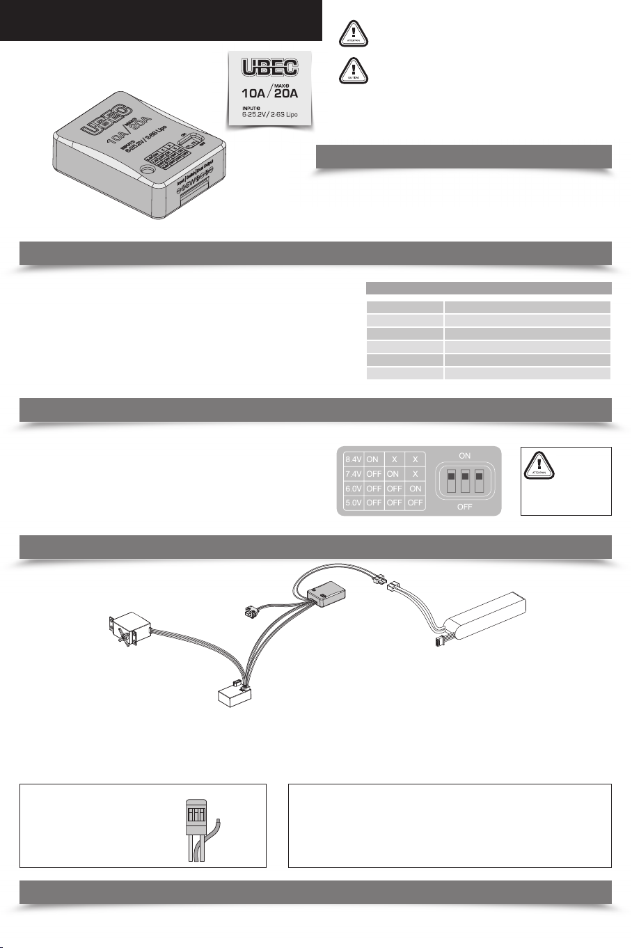
Der UBEC hat 3 Kodierschalter. Der Nutzer kann die Ausgangsspannung wie folgt ändern.
Einstellen auf 5,0V: Kodierschalter #1 = aus, #2 = aus, #3 = aus.
Einstellen auf 6,0V: Kodierschalter #1 = aus, #2 = aus, #3 = an.
Einstellen auf 7,4V: Kodierschalter #1 = aus, #2 = an, #3 = an oder aus (irrelevant).
Einstellen auf 8,4V: Kodierschalter #1 = an, #2 = an oder aus (irrelevant),
#3 = an oder aus (irrelevant).
Anmerkung: In Draufsicht auf das Vorderpanel des UBEC von links nach rechts sind die
Kodierschalter #1, #2, #3.
Vielen Dank, dass Sie dieses Produkt gekauft haben! Mit RC-Modellen
verwendete Geräte können gefährlich sein. Jeglicher nicht-bestimmungsgemäße Gebrauch kann zu Verletzungen und Schäden an
den Geräten führen. Versichern Sie daher, dass Sie diese Anleitung
vor Gebrauch lesen. Da wir keine Kontrolle über den Gebrauch, die
Installation und Wartung dieses Produktes oder ähnlicher Elektronik
haben, übernehmen wir keine Haftung für jegliche Schäden, Verluste
oder Kosten, die aus dem Gebrauch des Produktes entstehen.
Wir übernehmen darüber hinaus keine Verantwortung für jeglichen
Verlust, der durch die unerlaubte Veränderung unseres Produktes
entsteht. Wir behalten uns das Recht vor, unangekündigt Veränderungen am Produktdesign, Aussehen, Eigenschaften und Betriebsanforderungen vorzunehmen.
Specications
Model UBEC-10A
Eingangsspannung 6V–25,2V (2-6S LiPo)
Ausgangsspannung 5,0V/6,0V/7,4V/8,4V
Ausgangsstrom Dauerstrom: 10A, Höchststrom: 20A
Abmessung 43,1 x 32,3 x 12,5 mm
Gewicht 36g
„X“ zeigt an, dass dies Stellung des Kodierschalters in
ON oder OFF OK ist.
04 Anschluss
UBEC 10A
Schalter
Antrieb
Empfänger
1. Elektronische Drehzahlregler ohne eingebauten BEC
Der bürstenlose elektronische Drehzahlregler muss nicht verändert werden; der Nutzer muss nur den Eingang des UBEC mit den Batterieleitungen in Parallelschaltung verbin-
dung und den Ausgang (des UBEC) in einen freien Kanal des Empfängers stecken.
2. Elektronische Drehzahlregler mit eingebauten BEC
der Nutzer muss den eingebuaten BEC-Ausgang vom bürstenlosen elektronischen Drehzahlregler trennen. Das bedeutet, dass der rote Draht im Steuerkabel des elektronischen
Drehzahlkabel (siehe Abbildung unten) abgetrennt werden muss. DAnn muss der Eingang des UBEC in Paralellschaltung mit den Batterieleitungen verbunden werden und der
Ausgang (des UBEC) in einen freien Kanal des Empfängers gesteckt werden.
Tipps:
Sie können eine scharfen Schraubendreher verwenden, um den Pin (mit rotem Draht) aus dem
Steuerkabelstecker (JR-Stecker) des elektronischen Drehzahlreglers zu entfernen. Isolieren Sie
ihn dann mit etwas Isolierband für den weiteren
Gebrauch. Auf diese Weise müssen Sie den roten
Draht im Steuerkabel nicht abschneiden.
Nehmen Sie
den Pin mit
dem roten
Draht heraus
Anmerkung:
1. Da der schalbare Gleichstromregler bei Gebrauch elektronmagnetische Störungen verursachen und einige Empfänger von geringerer Qualität (insbesondere ältere AM/FM-Empfänger) beeinträchtigen kann, halten Sie den UBEC bei Einbau mindestens 5 cm entfernt vom
Emfpänger, um den normalen Betrieb dieser Empfänger sicherzustellen.
2. Die Polariät der Stromversorgung muss am Eingang mit der Polarität des UBEC übereinstimmen; eine inkorrekte Polarität is nicht zulässig. Bitte stellen Sie die korrkete
Verbindung vor dem Gebrauch sicher, andernfalls wird der UBEC stark beschägt.
Batterie
05 Erläuterung der Status-LED
Die rote LED leuchtet auf, wenn de UBEC verbunden ist, und zeigt an, dass die Ausgangsspannung des UBEC normal ist. Wenn die LED nicht aueuchtet, zeigt dies an, dass am
UBEC keine Ausgangsspannung anliegt; überprüfen Sie in diesem Fall bitte, dass alle Eingangsdrähte gut verbunden sind und die Batterie funktioniert.
Page 2
01 Introduction
02 Features
02 Features
• It adopted the advanced DC-DC regulator chip with conversion eciency exceeds 90%.
• 4 options for the output voltage, applicable for all kinds of receivers/gyros/servos, etc.
• It owns BEC shoot-through protection, which prevent the input voltage from directly owing
to the output end and causing damages to receivers, servos and other electronic devices.
• It featured other protections like over-current protection, short-circuit protection (at the
output end) and thermal protection make the use more safe and reliable.
• 2 cables are connected in parallel at the output end of the UBEC, allow larger current to ow
into the receiver.
• It has one status LED, which lights up when the UBEC works normally.
• The external switch can turn on/o the UBEC easily.
• Exquisite aluminum case is helpful for heat dissipation & EMI (Electromagnetic Interference)
reduction.
03 Change the Output Voltage
Change the Output Voltage
There are 3 dip switches on the UBEC. User can change the output voltage in the following
way.
Set to 5.0V: Dip switch #1 = O, #2 = O, #3 = O.
Set to 6.0V: Dip switch #1 = O, #2 = O, #3 = On.
Set to 7.4V: Dip switch #1 = O, #2 = On, #3 = On or O (irrelevant).
Set to 8.4V: Dip switch #1 = On, #2 = On or O (irrelevant), #3 = On or O (irrelevant).
Note: Face to the front panel of the UBEC, from left to right, the dip switches are #1, #2, #3.
Thank you for purchasing this product! Devices used on RC models
can be dangerous, any improper use may cause personal injury and
damage to devices, so please make sure to read through this manual
before use. In that we have no control over the use, installation and
maintenance of this product or other related electronics, no liability
may be assumed nor will be accepted for any damages, losses or
costs resulting from the use of the product.
Besides, we don’t shoulder any responsibility for any losses caused
by unauthorized modications to our product. The last but not
least, we have the right to change the product design, appearance,
features and operating requirements without notice.
The UBEC is an external switching mode DC-DC regulator; it draws
the DC voltage from 2-6S Lipo battery, drops it to a voltage level
that is suitable for receivers and other electronic devices, and keep
providing the stable current output of up to 10Amp. As the UBEC
has such a powerful output capability, so it is particularly applicable
for large helicopters and xed-wing aircrafts.
Specications
Model UBEC-10A
Input Voltage 6V–25.2V (2-6S LiPo)
Output Voltage 5.0V/6.0V/7.4V/8.4V
Output Amperage Continuous Current: 10A, Peak Current: 20A
Dimension 43.1x32.3x12.5mm
Weight 36g
„X“ indicates either the dip
switch is on the position of
ON or OFF is OK.
04 Wiring
UBEC 10A
Switch
Servo
1. When the ESC has no built-in BEC,
there’s no need to make any change to the brushless ESC, user only needs to connect the input end of the UBEC to the battery wires in parallel and plugs the output end (of
the UBEC) into any unoccupied channel onthe receiver.
2. When the ESC has a built-in BEC,
user needs to disconnect the built-in BEC output on the brushless ESC; that means disconnecting the red wire in the ESC control cable (please see the picture below), then
connect the input end of the UBEC to the battery wires in parallel, and plug the output end (of the UBEC) into any unoccupied channel on the receiver.
Tips:
You can use a sharp screwdriver to take the
pin (with red wire) out from the control cable
plug (JR male connector) of the ESC, and
then insulate it with a bit of electrical tape for
further use. By this method, you needn’t cut
the red wire in the control cable.
Receiver
Take the
pin with
red wire out
Note:
1. As the switching mode DC-DC regulator may produces some electromagnetic interference in operation and aects some poor-quality receivers (especially the outdated AM/FM
receivers), so for ensuring the normal operation of those receivers, please keep the UBEC
at least 5cm away from receivers when it’s installed.
2. Polarity of the power supply must be aligned with the polarity of the UBEC at the input
end, incorrect polarity is not permitted. So please ensure the correct connection before
use; otherwise, the UBEC will be seriously damaged.
Battery
05 Explanation for the Status LED
Red LED lights up when the UBEC is connected to the battery indicating the UBEC outputs voltage normally. If the LED doesn’t come on indicating the UBEC doesn’t output
any voltage; in that case, please check if all the input wires are well connected and there’s nothing wrong with the battery pack.
Page 3

01 Introduction
02 Features
02 Caractéristiques
•
Il a adopté la puce du régulateur DC-DC de pointe avec un rendement de conversion supérieur à 90 %.
• 4 options pour la tension de sortie, applicables à tous les types de récepteurs / gyros / servos, etc.
• Il possède une protection BEC contre les courts-circuits, qui empêche la tension d’entrée de circuler
directement à la sortie, ce qui causerait des dommages aux récepteurs, servos et autres appareils
électroniques.
• Il a présenté d’autres protections comme la protection contre les surintensités, la protection contre
les courts-circuits (à la sortie) et la protection thermique, qui rendent l’utilisation plus sûre et able.
• 2 câbles sont connectés en parallèle à la sortie de l’UBEC, et permettent au courant plus puissant de
circuler dans le récepteur.
• Il dispose d’une DEL d’état, qui s’allume lorsque l’UBEC fonctionne normalement.
• Le commutateur externe peut activer / désactiver l’UBEC facilement.
• Le boîtier en excellent aluminium est utile pour la réduction de la dissipation thermique et de l’EMI
(interférences électromagnétiques).
03 Modication de la tension de sortie
Modication de la tension de sortie
3 commutateurs DIP sont présents sur l’UBEC. L’utilisateur peut changer la tension de sortie
de la manière suivante.
Régler à 5,0 V : Commutateur DIP n° 1 = O, n° 2 = O, n° 3 = O.
Régler à 6,0 V : Commutateur DIP n° 1 = O, n° 2 = O, n° 3 = On.
Régler à 7,4V : Commutateur DIP n° 1 = O, n° 2 = On, n° 3 = On ou O (sans importance).
Régler à 8,4V : Commutateur DIP n° 1 = On, n° 2 = On ou O (sans importance),
n° 3 = On ou O (sans importance).
Note : Face au panneau avant de l’UBEC, de gauche à droite, les commutateurs DIP sont
dans l’ordre n° 1, n° 2, n° 3
Merci d’avoir acheté ce produit ! Les dispositifs utilisés sur les
modèles RC peuvent s’avérer dangereux, toute mauvaise utilisation
peut entraîner des blessures et des dommages aux appareils, donc
veuillez vous assurer de lire ce manuel avant utilisation. Puisque nous
n’avons aucun contrôle sur l’utilisation, l’installation et l’entretien
de ce produit ou d’autres appareils électroniques connexes, aucune
responsabilité ne peut être assumée ni ne sera acceptée pour tous
dommages, pertes et coûts résultant de l’utilisation du produit.
De plus, nous n’endossons aucune responsabilité pour les pertes
causées par des modications non autorisées de notre produit. Un
dernier point mais non des moindres, nous avons le droit de modier
la conception, l’apparence, les caractéristiques
L’UBEC est un régulateur commutable DC-DC externe ; il puise la tension
continue de la batterie 2-6S Lipo, et tombe à un niveau de tension
adapté pour les récepteurs et autres appareils électroniques, et fournit
en continu le courant de sortie stable, jusqu’à 10 A. Comme l’UBEC a une
capacité de sortie aussi puissante, il est donc particulièrement applicable
pour de grands hélicoptères et des avions à voilure xe.
Spécications
Model UBEC-10A
Tension d’entrée 6 V–25,2 V (2-6S LiPo)
Tension de sortie 5,0 V / 6,0 V / 7,4 V / 8,4 V
Intensité de sortie Courant continu : 10 A, Courant de crête : 20 A
Dimension 43,1 x 32,3 x 12,5 mm
Poids 36 g
« X » indique si le commutateur DIP est en position ON
ou OFF, d’une façon correcte.
04 Câblage
UBEC 10A
Commutateur
Servo
Récepteur
1. Lorsque l’ESC n’a pas de BEC intégré,
il n’est pas nécessaire de modier l’ESC sans balais, l’utilisateur doit juste relier l’entrée de l’UBEC aux ls de la batterie en parallèle et brancher la sortie (de l’UBEC) dans
n’importe quel canal inoccupé sur le récepteur.
2. Lorsque l’ESC a un BEC intégré,
l’utilisateur doit débrancher la sortie du BEC intégré sur l’ESC sans balais ; cela signie le débranchement du l rouge dans le câble de commande de l’ESC (veuillez consulter le
tableau ci-dessous), puis connectez l’entrée de l’UBEC aux ls de la batterie en parallèle, et branchez la sortie (de l’UBEC) dans n’importe quel canal inoccupé du récepteur.
Astuces :
Vous pouvez utiliser un tournevis pointu pour
sortir la broche (avec l rouge) de la prise du
câble de commande (connecteur mâle JR) de
l’ESC, puis l’isoler avec un peu de ruban élec-
trique pour une utilisation ultérieure. De cette
façon, vous n’avez pas à couper le l rouge
dans le câble de contrôle.
Sortez la
broche
avec le l
rouge
Note :
Comme le régulateur commutable DC-DC peut produire des interférences électromagné-
1.
tiques lors de son fonctionnement et aecte certains récepteurs de mauvaise qualité (en
particulier les récepteurs AM / FM obsolètes), pour s’assurer du fonctionnement normal de
ces récepteurs, veuillez placer l’UBEC à au moins 5 cm des récepteurs, quand il est installé.
2. La polar
ité de l’alimentation doit être alignée avec la polarité de l’UBEC à l’entrée, une
polarité incorrecte n’est pas autorisée. Donc, veuillez vous assurer que la connexion est
correcte avant utilisation ; sinon, l’UBEC sera sérieusement endommagé.
Batterie
05 Explication de l’état de la DE
Une DEL rouge s’allume lorsque l’UBEC est connecté à la batterie indiquant normalement la tension des sorties de l’UBEC. Si la DEL ne s’allume pas, cela signie que l’UBEC ne
produit pas de tension ; dans ce cas, veuillez vérier si tous les ls d’entrée sont bien connectés et que la batterie n’a pas de défauts.
Page 4

01 Inleiding
02 Features
02 Kenmerken
•
Het maakt gebruik van de geavanceerde DC-DC-regelaarchip. Het omzettingsrendement is hoger dan 99%
• 4 opties voor de uitgangsspanning, toepasbaar voor alle soorten ontvangers/gyroscopen/servo‘s, enz.
• Het bezit een BEC-overschrijdingsbeveiliging, die voorkomt dat de ingangsspanning direct naar het
einde van de uitgang stroomt en daar schade veroorzaakt aan ontvangers en overige elektronische
apparaten.
• Het heeft andere beveiligingen zoals overstroombeveiliging, kortsluitingsbeveiliging (op het uitgangseinde) en thermische bescherming om het gebruik veiliger en betrouwbaarder te maken.
• Parallel aan het uitgangseinde van de UBEC worden 2 kabels aangesloten, waardoor er meer stroom
naar de ontvanger kan stromen.
• Het heeft één status-LED, dat gaat branden wanneer de UBEC normaal functioneert.
• De externe schakelaar kan de UBEC gemakkelijk aan-/of uitschakelen.
•
Verjnde aluminium behuizing helpt bij de warmteafvoer & EMI- (elektromagnetische storing) vermindering.
03 Wijzig de uitgangsspanning
Wijzig de uitgangsspanning
De UBEC heeft 3 DIP-schakelaars De gebruiker kan de uitgangsspanning op de volgende
manier wijzigen:
Instellen op 5,0V: Dip -schakelaar #1 = Uit, #2 = Uit, #3 = Uit.
Instellen op 6,0 V: Dip-schakelaar #1 = Uit, #2 = Uit, #3 = Aan.
Instellen op 7,4V: Dip-schakelaar #1 = Uit, #2 = Aan, #3 = Aan of Uit (n.v.t.).
Instellen op 8,4V: Dip-schakelaar #1 = Aan, #2 = Aan of Uit (n.v.t.), #3 = Aan of Uit (n.v.t.).
Opmerking: Bekijk het UBEC-paneel aan de voorzijde, van links naar rechts, de DIP-schakelaars
zijn #1, #2, #3.
Hartelijk dank voor de aankoop van dit product! Apparaten die met
op afstand bestuurbare modellen worden gebruikt kunnen gevaarlijk
zijn. Onjuist gebruik kan persoonlijk letsel en schade aan apparatuur
veroorzaken. Lees daarom deze gebruiksaanwijzing zorgvuldig voorafgaand aan het gebruik. We hebben geen controle over het gebruik,
de installatie en het onderhoud van dit product of overige gerelateerde elektronica. We accepteren geen verantwoordelijkheid voor schade,
verliezen of kosten resulterend uit het gebruik van het product.
We nemen daarnaast geen verantwoordelijkheid voor verliezen die
voortkomen uit niet geautoriseerde aanpassingen aan ons product.
En als laatste hebben we het recht om het productontwerp, uiterlijk,
kenmerken en gebruiksvereisten te wijzigen zonder voorafgaande
melding.
De UBEC is een externe schakelaarmodus DC-DC-regelaar; het ontvangt
de DC-spanning van een 2-6S-LiPo-accu, verlaagt het tot een spannings-
niveau dat geschikt is voor ontvangers en overige elektronische apparaten
en zorgt voor een stabiele stroomuitvoer van max. 10 A. Aangezien de
UBEC een zeer stabiel uitvoervermogen heeft, is het vooral toepasbaar
voor grote helikopters en vliegtuigen met gexeerde vleugel.
.
Gegevens
Model UBEC-10A
Ingangsspanning 6 V–25,2 V (2-6S LiPo)
Uitgangsspanning 5,0 V/6,0 V/7,4 V/8,4 V
Uitgang Ampère Permanente stroom: 10 A, Piekstroom: 20 A
Afmeting 43,1x32,3x12,5 mm
Gewicht 36 g
„X“ geeft „OK“ aan
wanneer de DIP-schakelaar in de aan-stand of
uit-stand AAN of UIT
04 Bedrading
UBEC 10A
Schakelaar
Servo
Ontvanger
1. Als de ESC geen ingebouwde BEC heeft,
is er geen wijziging nodig aan de borstelloze ESC. De gebruiker moet alleen het ingangseinde van de UBEC parallel aansluiten op de accudraden, en het uitgangseinde (van de
UBEC) in een vrij kanaal op de ontvanger steken.
2. Als de ESC een ingebouwde BEC heeft,
moet de gebruiker de ingebouwde BEC-uitgang op de borstelloze ESC onderbreken; dit betekent het onderbreken van de rode draad in de ESC-besturingskabel (zie de onderstaande afbeelding). Verbind daarna het ingangseinde van de UBEC parallel naar de accudraden, en steek het uitgangseinde (van de UBEC) in een vrij kanaal op de ontvanger.
Aanwijzingen:
U kunt een scherpe schroevendraaier gebruiken
om het pennetje (met rode draad) uit de besturingskabelsteker (JR-aansluiting, mannetje) uit de
ESC te halen, om het vervolgens met een stukje
isolatietape te isoleren om het verder te kunnen
gebruiken. Hierdoor hoeft u de rode draad in de
besturingskabel niet door te knippen.
Neem de
pen met
de rode
draad eruit
Opmerking:
1. De schakelaarmodus DC-DC-regelaar kan tijdens gebruik enige elektromagnetische storing
veroorzaken en beïnvloedt enkele minder kwalitatieve ontvangers (vooral de oudere AM/
FM-ontvangers). Zorg ervoor dat de UBEC op minimaal 5 cm afstand staat van de ontvan-
gers tijdens de installatie, om een normale werking te garanderen.
2. De polariteit van de stroomvoorziening moet gelijk zijn aan de polariteit van de UBEC
aan het uitgangseinde. Onjuiste polariteit is niet toegestaan. Zorg daarom voor de juiste
aansluiting voorafgaand aan het gebruik; anders zal de UBEC ernstig beschadigd raken.
Accu
05 Uitleg van de status-LED
De rode LED gaat branden wanneer de UBEC met de accu is verbonden. Het geeft aan dat de UBEC-uitgangsspanning normaal is. Als de rode LED niet gaat branden en dus
weergeeft dat de UBEC geen spanningsuitgang heeft, controleer dan in dat geval of alle ingangsbedrading goed zijn aangesloten en het accupack naar behoren functioneert.
 Loading...