

Page 1

Version 12/06
OPERATING INSTRUCTIONS
Radio smoke detector
„RM 100-2 Uni-S“
Item no. 75 06 66
Page 2

2
Table of contents
Page
1. Introduction ................................................................................................................. 4
2. Prescribed use ............................................................................................................ 5
3. Scope of delivery ........................................................................................................ 6
4. Explanation of icons .................................................................................................. 6
5. Safety instructions ..................................................................................................... 7
6. Notes on batteries and rechargeable batteries ..................................................... 8
7. Features and functions .............................................................................................. 9
8. Selecting the installation location ......................................................................... 10
9. Installation ................................................................................................................. 13
10. Initial operation ......................................................................................................... 14
a) Setting the house code for the smoke detector### ........................................... 14
b) Setting the house code for the ‘FHZ 1000’ ......................................................... 15
c) Switching the ‘HMS 100’ function on and off ...................................................... 16
d) Starting the sensor search on the ‘HMS 100 Z’ ................................................. 17
e) Inserting the batteries into the smoke detector .................................................. 18
f) Starting the sensor search on the ‘HMS 100 Z’ ................................................. 19
g) Locking the smoke detector into its socket ........................................................ 19
11. Function control and operation ............................................................................. 20
a) Control panel & function test ............................................................................... 20
b) Alarm indicator on the ‘HMS 100 Z’ .................................................................... 21
c) Alarm indicator on the ‘FHZ 1000’ ...................................................................... 21
d) Periodic monitoring and error display ................................................................. 21
12. Wired connection of several smoke detectors .................................................... 23
13. Replacing the batteries ............................................................................................ 26
a) General information ............................................................................................. 26
b) Setting the ‘HMS 100 Z’ to the maintenance mode ........................................... 27
c) Replacing the batteries ....................................................................................... 28
d) Quitting the maintenance mode of the ‘HMS 100 Z’ .......................................... 29
Page 3

3
Page
14. Escape plan ................................................................................................................30
15. Information on the radio range ............................................................................... 32
16. Maintenance and cleaning ....................................................................................... 33
17. Disposal ...................................................................................................................... 33
a) General information .............................................................................................. 33
b) Batteries and rechargeable batteries .................................................................. 33
18. The smoke detector’s signal output ....................................................................... 34
19. Declaration of conformity (DOC) ............................................................................. 34
20. Technical specifications ........................................................................................... 35
Page 4

4
1. Introduction
Dear customer,
Thank you for purchasing this product.
This product meets the requirements of both current European and national guidelines.
In order to preserve this condition and ensure the safe operation of the product we kindly ask
you to carefully follow these operating instructions!
Please read the operating instructions completely and observe the safety and operation notes
before using the product!
All company names and product names contained herein are trademarks of the
respective owners. All rights reserved.
Should you have any further questions, please contact our technical advisory service:
Germany: Tel. no.: +49 9604 / 40 88 80
Fax. no.: +49 9604 / 40 88 48
e-mail: tkb@conrad.de
Mon. to Thur. 8.00am to 4.30pm
Fri. 8.00am to 2.00pm
Page 5
5
2. Prescribed use
The ‘RM 100-2 Uni-S’ smoke detector registers smoke emissions (smouldering fire and open
fires with smoke emissions) and sets off an alarm when the smoke concentration reaches a
certain level.
The alarm is carried out via the integrated signal transmitter and a red warning LED. A bright,
white LED is also activated as an emergency light.
The smoke alarm is simultaneously radio-transmitted to the
‘HMS 100 Z’ central unit of the
‘HMS 100’ hazard detection system or the ‘FHZ 1000’ home radio central unit. This ensures
that a fire, which is some distance away (on another floor of the house, for example), can be
responded to in good time.
A smoke alarm can also be relayed by cable when several smoke detectors of this type are
connected by cable.
This allows rooms to be monitored whose current conditions make radio
monitoring technically difficult.
For further information please see section 7.
The radio smoke detector should not be used in environments such as hospitals with lifesupport systems or other similar environments in which the transmission of radio signals may
cause devices to malfunction.
Batteries must be used to power the smoke detector.
The product should only be installed and operated in dry indoor locations. Make sure it does
not get damp or wet.
No part of the device may be modified or adapted. Doing so invalidates the licence (CE) and
the guarantee/warrantee.
The manufacturer does not assume liability for damages caused by the improper use of the
device. All guarantees and guarantee claims will be invalidated in such cases.
The device may only be operated when its casing is fully closed.
All the safety instructions and installation notes in this manual must be
observed without fail.
Page 6
6
3. Scope of delivery
• ‘RM 100-2 Uni-S’ smoke detector
• Spacers for mounting
• User manual
4. Explanation of icons
The icon with a lightning flash in a triangle is used to alert you to potential
personal injury hazards such as electric shock.
The icon with an exclamation mark in a triangle points to important instructions
in this user manual that must be observed.
The ‘hand’ symbol provides special information and advice on operating the
device.
Page 7
7
5. Safety instructions
The product’s guarantee becomes invalid, if the product is damaged as
a result of the failure to observe these operating instructions! We do not
assume any liability for any resulting damages!
Nor do we assume liability for damage to property or personal injury
caused by improper use or failure to observe the safety instructions. In
such cases the product’s guarantee becomes invalid.
• Do not use this product in hospitals or medical institutions. Although the product emits only
relatively weak radio signals, these may cause life-support systems to malfunction. This
may also be the case in other areas.
• If, during mounting, connection or installation you are not sure or have doubts about how
to proceed, contact a skilled technician.
• For safety and licensing (CE) reasons any unauthorised alterations to and/or modification
of the product are not permitted.
• The product is only approved for installation and operation in dry and closed indoor rooms.
Make sure that the product does not get damp or wet. Do not expose the device to direct
sunlight and avoid using it in dusty environments.
• The smoke detector must not be painted or pasted over with wall paper.
• This product is not a toy and should be kept out of the reach of children. The product should
not be stored or used within the reach of children.
• Do not leave packaging material lying around. This may become a dangerous plaything in
the hands of children.
• You should carry out a function test once a month by pressing the test button.
Page 8
8
6. Notes on batteries and rechargeable batteries
For safety reasons, the smoke detector should not be operated using rechargeable batteries.
Due to the its low voltage (rechargeable battery = 1.2V, battery = 1.5V) the
smoke alarm may perceive that the rechargeable battery is low even though it
is fully charged. It then emits a soft signal tone every 48 seconds and the red
LED blinks three times every 48 seconds.
Therefore, please make sure that you only use high-quality alkaline batteries
(Conrad item no. 650117, for example. Order 3 batteries).
• Keep batteries (and rechargeable batteries) out of the reach of children.
• Make sure that the polarity is correct when inserting the batteries.
• Do not leave batteries/rechargeable batteries lying around as they could be swallowed by
children or pets. In such case seek immediate medical care.
• Leaking or damaged batteries/rechargeable batteries may cause acid burns, if they come
into contact with skin. Therefore, please make sure you use suitable protective gloves.
• Make sure that batteries/rechargeable batteries are not short-circuited, taken apart or
thrown into fire. They might explode!
• Conventional batteries must not be recharged. They might explode!
• If the device is not used for a longer period of time (when stored, for example), remove the
inserted batteries. This way, you can prevent the aging batteries from leaking and causing
damage.
For safety reasons, the device’s casing cannot be locked, if no batteries
have been inserted!
Page 9

9
7. Features and functions
The ‘RM 100-2 Uni-S’ smoke detector registers smoke emissions (smouldering fires and open
fires with smoke emissions) optically using the scattered light principle.
When the smoke concentration reaches a specific level, the smoke detector activates the
integrated signal transmitter. A red warning LED is also activated as well as a white LED, which
serves as an emergency light.
A smoke alarm is simultaneously transmitted to an existing ‘HMS 100 Z’ central unit belonging
to the ‘HMS 100’ hazard detection system or the ‘FHZ 1000’ home radio central unit.
This ensures that a fire, which is some distance away (on another floor of the
house, for example), can be responded to in good time.
Furthermore, several smoke detectors in the ‘RM 100’ series can be connected by cable,
allowing the smoke alarm to be relayed by cable.
This allows rooms to be monitored whose current conditions make radio
monitoring technically difficult.
In order to avoid crossovers with other radio services operating on the 868 MHz frequency
band, the system can be coded using a house code. This protects the system from false alarms
caused by other radio transmitters operating in the same frequency range.
Page 10
10
1m
8. Selecting the installation location
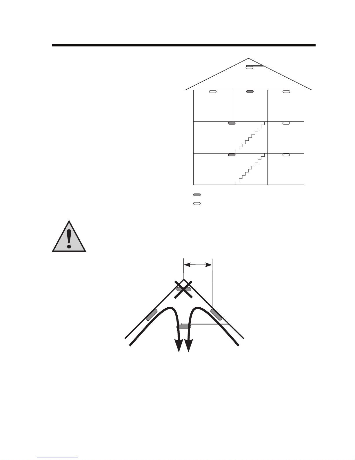
We generally recommend that several smoke
detectors be installed in a building or an
apartment. One smoke detector should definitely be installed on each floor of a multistorey building. This is the only way to ensure that an effective warning is issued in
time when a fire starts.
Smoke detectors should be installed in such
a way that they safeguard a route to the
bedroom (entrance area, hall or stairway).
And, when an alarm sounds, they must also
be audible through a closed bedroom door.
The smoke detector should always be
mounted to the centre of a room’s ceiling.
Bedroom
Hallway
Study Living
room
Children’s
room
Entrance area Kitchen
Minimal protection
Recommended protection
When installed in an attic room with a pointed roof, the smoke detector should
not be attached to the highest point of the room as here there is hardly any
movement of air. An ideal installation location would be a roof beam or an
overhang beam.
Smoke
Air pockets that keep the rising smoke away collect close to the walls, and also in the corners
of rooms and where there are sharp-angled ceilings. This makes the smoke detector take a
lot longer to detect smoke and trigger its alarm.
Page 11

11
In normal rooms, the smoke detector should be installed at least 60
cm away from the corners of the
room.
Radiators, window sills, windows
and even furniture affect the circulation of air.
Ideally you should mount it to the
ceiling in the centre of the room.
60cm60cm
60cm
Smoke
If you select an unsuitable installation location the smoke detector will remain
more or less useless when a fire starts; only triggering an alarm when the
smoke concentration reaches a very high level.
This will significantly reduce the amount of time available for saving yourself
and others from danger or for extinguishing the fire.
Window sills, curtains or furniture strongly influence the circulation of air, and
thus, the movement of smoke. They create a zone of dormant air. This means
that rising smoke does not reach the smoke detector or it reaches it too late!
We generally recommend that the smoke detector be mounted to the ceiling in
the centre of a room. However, you should make sure that you do not install the
device directly under any lights (halogen lamps, for example).
You can check whether the alarm is sufficiently loud enough to wake someone up from its
installation location by setting off a test alarm (see ‘Installation’) while someone is asleep in
the bedroom.
The smoke detector should be loud enough to wake people up! It should
not just be audible!
You should also carry out extensive checks to make sure that the radio signals sent by each
of the smoke detectors from their installation locations will reach the ‘HMS 100 Z’ or ‘FHZ 1000’
central unit.
In general, reception problems are not experienced in most single family
houses. As you can see in section 15 (‘Information on the radio range’),
however, many things can restrict the radio reception.
Page 12

12
For example, reinforced concrete ceilings or electric floor-heating systems can
hinder reception between several floors.
Electric cables, electric devices or metal objects can also reduce the range.
It can be difficult to install the smoke detector in the following rooms and locations:
• Kitchen/bathroom: False alarms due to kitchen steam or high levels of humidity
• Garages: False alarms due to exhaust gases from cars, motorcycles or other combustion
engines
• Living rooms with an open fireplace: False alarms due to escaping smoke
• Dusty and dirty rooms: Dirt on the measurement chamber causes the smoke detector to
become less sensitive so that the alarm is activated later or not at all
• Places with a strong movement of air: Late smoke detection and alarm due to the
proximity of windows, fans, lamps, lamp tubes, halogen transformers, radiators, fireplaces
• Proximity to metal/electric devices: Deterioration of the radio range due to steel beams,
large metal surfaces, metal doors, televisions, power cables and so on
• Smoke from tobacco: False alarms as the smoke detector cannot differentiate between
‘harmless’ tobacco smoke and a real fire
Some smoke detectors have a sensitivity setting. The disadvantage of this,
however, is that the alarm is triggered late when a ‘real’ fire occurs, and this
shortens the response time considerably. The time that is available for
extinguishing the fire, for saving people or for escaping is considerably
reduced!
Page 13

13
9. Installation
Please make sure you read the information on selecting an installation location
provided in section 8.
• Remove the smoke detector’s upper plate by carefully twisting the upper plate and the lower
plate against each other (anticlockwise).
The upper and lower plates can only be locked firmly, once the batteries have
been inserted.
A
B
C
A Mounting holes for installation using an
installation box
B Holder for cable ties
C Alternative installation using spacers
• You can use the two mounting holes to screw the lower plate securely to a wall or a ceiling,
for example.
Depending on the type of surface, you may have to first drill two mounting holes and insert
suitable dowels.
When drilling or screwing be careful not to accidentally damage any
power supply lines, gas or water pipes. Life-threatening danger!
• Alternatively, the lower plate can be mounted using the two spacers (if cables run under the
smoke detector, for example) or via the screws of an installation box.
Page 14

14
0 000
1 001
2 002
3
003
4
004
5
005
6
006
7
007
8
008
9
009
10
010
11
011
12
012
13
013
14
014
15
015
1
2345
ON DIP
1
2345
ON DIP
1
2345
ON DIP
1
2345
ON DIP
1
2345
ON DIP
1
2345
ON DIP
1
2345
ON DIP
1
2345
ON DIP
1
2345
ON DIP
1
2345
ON DIP
1
2345
ON DIP
1
2345
ON DIP
1
2345
ON DIP
1
2345
ON DIP
1
2345
ON DIP
1
2345
ON DIP
1
2345
ON DIP
10. Initial operation
Initial operation varies for the two ‘HMS 100’ and ‘FHZ 1000’ systems. Please
make sure you read the following subsections.
a) Setting the house code for the smoke detector
You only need to set this house code, if the smoke detector is operated as part
of the ‘FHZ 1000’ system!
House code RM100-2 Uni-S FHZ1000
Code on
the display
Use the DIP switches 1 to 4 to set a
house code (freely selectable between
0 and 15).
The same code must also be set for the
‘FHZ 1000’.
This code stops neighbouring radio
smoke detectors from triggering unintentional alarms on the ‘FHZ 1000’.
Page 15

15
b) Setting the house code for the ‘FHZ 1000’
You only need to set this house code, if the smoke detector is operated as part
of the ‘FHZ 1000’ system!
Proceed as follows:
• Press the ‘x’ button on the ‘FHZ 1000’.
• Turn the scroller on the ‘FHZ 1000’ until ‘
Sonderfkt.Sonderfkt.
Sonderfkt.Sonderfkt.
Sonderfkt.’ appears on the display.
• Keep the ‘PROG’ button pressed until ‘
Ext. AlarmExt. Alarm
Ext. AlarmExt. Alarm
Ext. Alarm’ appears on the display of the ‘FHZ
1000’.
• Use the scroller to set the house code that you previously set for the ‘RM 100-2 Uni-S’
smoke detectors.
• Press the ‘PROG’ button. The setting is applied and the menu closes.
• It is not necessary to separately register the smoke detector to the ‘FHZ 1000’. Only the
alarm priority may still need to be set up according to the FHZ 1000’s user manual.
Page 16

16
c) Switching the ‘HMS 100’ function on and off
The ‘RM 100-2 Uni-S’ radio smoke detectors transmit a status signal every 30 minutes
(including, amongst other things, the battery level) to the ‘HMS 100 Z’ central unit.
DIP switch 5 must be in the ‘ON’ position for this function to work.
1
2345
ON DIP
‘HMS 100’ function on
If you do not intend to operate the smoke detector as part of the ‘HMS 100’ system, you can
use DIP switch 5 to switch off the ‘HMS 100’ radio protocol.
This extends the battery life.
1
2345
ON DIP
‘HMS 100’ function off
Alarms are still transmitted to the ‘FHZ 1000’ home radio central unit irrespec-
tive of this setting, provided that the house code matches.
Page 17

17
d) Starting the sensor search on the ‘HMS 100 Z’
You only need to set this, if the smoke detector is operated as part of the
‘HMS 100’ system!
Proceed as follows:
• When the ‘HMS 100 Z’ is in normal operation, press the ‘MENU’ button. ‘
StörungenStörungen
StörungenStörungen
Störungen
bearbeitenbearbeiten
bearbeitenbearbeiten
bearbeiten’ appears on the display.
• Use the scroller or the ‘x’ and ‘w’ buttons to select the ‘
Sensor einstellenSensor einstellen
Sensor einstellenSensor einstellen
Sensor einstellen” menu
item.
• Press the ‘OK’ button.
‘
Sensor hinzufügenSensor hinzufügen
Sensor hinzufügenSensor hinzufügen
Sensor hinzufügen’ appears on the HMS 100 Z’s display.
• Press the ‘OK’ button again.
‘
SensorsucheSensorsuche
SensorsucheSensorsuche
Sensorsuche’ appears on the display.
• Now insert the batteries into the smoke detector, as described in section 10 e).
• Then complete the registration. See section 10 f).
Page 18

18
e) Inserting the batteries into the smoke detector
• Have you already set the ‘HMS 100 Z’ to the sensor search mode?
If you have not done so already, remove the batteries and first follow the instructions
provided on the previous page in section 10 d).
• Insert three new AA batteries (LR06, Conrad item no. 650117, for example) into the three
battery holders, making sure that the polarity is correct. Useful figures are located in the
battery compartments.
As described in chapter 6, we recommend that you use high-quality alkaline
batteries.
• Once the batteries have been inserted, the red control indicator blinks approx. every 48
seconds to signal that the smoke detector is ready to be used.
+
+
+
-
-
-
+
-
+
+
-
-
Page 19

19
f) Completing the sensor search on the ‘HMS 100 Z’
You only need to set this, if the smoke detector is operated as part of the
‘HMS 100’ system!
• Once the central unit has received the signal from the radio smoke detector, ‘
Sensor xxSensor xx
Sensor xxSensor xx
Sensor xx’
(xx = 01-30) appears on the display. The smoke alarm symbol is also displayed.
A cursor appears on the lower display line (entry bar). Here you can enter a name for the
smoke detector in plain text that is up 11 positions long.
• Use the ‘x’ and ‘w’ buttons to select the desired entry position (this also allows you to enter
space characters) and use the scroller to set the character you require (alphabet, umlauts,
digits, space characters) at the cursor position.
• Then select the next position using the ‘x’ and ‘w’ buttons and repeat the procedure until
you have entered the complete name.
You can also use the ‘x’ and ‘w’ buttons and the scroller to subsequently modify the text
you have entered.
You can also delete characters that have been entered using the space character (after ‘9’
or before ‘A’). You can delete the whole name all at once using the ‘Löschen’ button
(= ‘Delete’).
• Once you have entered the name, press ‘OK’.
g) Locking the smoke detector into its socket
Insert the smoke detector into the mounted lower plate by turning it clockwise. The red triangles
fitted in the lower plate and in the smoke detector help you to position it correctly.
Please note:
For safety reasons, the two parts of the casing (lower plate/smoke
detector) cannot be locked, if no batteries have been inserted!
Page 20

20
11. Function control and operation
a) Control panel & function test
• After mounting the smoke detector you should carry out a function test.
A
B
C
A Opening for acoustic signal trans-
mitter
B Test button with LED indicator
C Optical signal transmitter (emer-
gency light) lights up together with
the acoustic signal transmitter
• Blow tobacco smoke, for example, onto the smoke detector. Once the smoke has
penetrated the smoke chamber inside the smoke detector, the alarm is activated, so long
as smoke is still located in the smoke detector’s smoke chamber.
A triggered alarm is signalised by an acoustic and an optical signal (about every second).
• The alarm is automatically terminated after 48 seconds once the smoke alarm’s electronics
in the smoke chamber no longer detect any smoke.
• The red control indicator of the triggering smoke alarm continues to blink for about ten
minutes after the alarm has terminated. This makes it easier to find the triggering alarm
when there is a false alarm, for example.
• Pressing the test button for approx. 2 seconds (press the button up to the pressure point)
causes the acoustic alarm to stop for approx. 10 minutes.
If there is still smoke in the smoke chamber, the LED continues to blink. Otherwise the alarm
stops completely.
Page 21

21
b) Alarm indicator on the ‘HMS 100 Z’
When an alarm is triggered the ‘ ’ symbol should appear on the central unit’s display (select
display type ‘Aktuell’).
The smoke detector transmits a status signal to the control centre every 30
minutes, which serves to control the connection and also includes the battery
level.
c) Alarm indicator on the ‘FHZ 1000’
An acoustic signal is used to audibly indicate that an alarm has been triggered, while an
exclamation mark appears on the lower left of the display to optically indicate that an alarm has
been triggered.
d) Periodic monitoring and error display
You can find an overview of the smoke detector’s optical and acoustic output
in section 18.
You should check that the smoke detector is working once a month. To do this, press the test
button for approx. 2 seconds (press the button to the pressure point).
• If the acoustic signal sounds once and the LED blinks 10 times, then the smoke detector
is working properly.
• If, after pressing the button, only the LED starts to blink, then the smoke detector is faulty
and must be replaced.
• If no signals are emitted, then the batteries are flat. Replace the old batteries with a
complete set of new batteries.
Page 22

22
To replace the batteries make sure you follow the instructions provided in
section 13.
For safety reasons, a particular procedure must be followed when replacing the
batteries,
if the smoke detector is part of a ‘HMS 100’ radio system (the central
unit stores the battery level as a ‘fault’ (= ‘Störung’)).
Note that the ‘HMS 100 Z’ should first be set to the maintenance mode
before its batteries can be replaced!
• If the batteries are in good condition, then the smoke detector is likely to be faulty and must
be replaced.
Page 23

23
12. Wired connection of several smoke detectors
Many installation locations allow no radio reception or only poor reception. This may be due
to how the building is constructed, for example, (reinforced concrete, metal-dampened
insulation glass windows, metal doors and so on). Also see section 15 ‘Information on the radio
range’.
To ensure that an alarm is still triggered when a fire with smoke emissions
starts, the smoke alarms can be connected to each other by cable.
This also allows a smoke detector to relay an alarm over long distances (from neighbouring
buildings, garages and so on). You can also connect any existing ‘RM 100’ smoke detectors
without radio at any time.
A twisted, two-core connecting cable should be used (of the type ‘J-Y(ST)Y2 x 2 x 0.6mm’, for
example, or a similar rigid installation cable). A total cable length of up to 400m is feasible in
the ideal case.
You can connect up to 40 smoke detectors of the type ‘RM 100’ with one
another via cable (in the case of a radio connection you can connect any
number of smoke detectors).
Proceed as follows to connect the cables:
• First of all, remove any batteries that may be inserted in the smoke alarms.
• When the cables are wall-mounted (in a garage or in a neighbouring building, for example)
the smoke detector’s lower plate should be mounted using the supplied spacers so that you
can lay the cables under the smoke detector and then lead them inside the casing.
Otherwise, the cables will get damaged/pinched.
• Guide the cables through the lower plate’s opening and use a cable tie to fix them, at the
length you require, to the lower plate’s holder. Allow for enough additional cable length so
that you have no difficulty in replacing the batteries later.
• Strip the cable ends at a length of approx. 6mm.
Page 24

24
+
-
+
-
-
-
-
+
+
+
+
-
-
-
-
+
+
+
-
-
-
+
+
+
-
-
-
+
+
+
+
-
Observe the correct polarity!
Cable terminal
Installation of cable in the device when using radio modules
Avoid contacting the cable with
the antenna loop on the circuit
board!
Page 25

25
• Pull the cable terminal out slightly and insert the stripped cable ends into the terminals.
When doing so, make sure you observe the correct wiring, see the figure
above! Always connect the positive terminals with one another and then the
negative terminals. Connecting these incorrectly will destroy all the smoke
detectors! Markings illustrating the polarity (+/-) are embossed next to the cable
terminal.
• Reinsert the cable terminal and check once again that the polarity of the wiring is correct.
• Connect the smoke detectors as shown in the figure on the previous page. Always observe
the correct wiring/polarity. Guide the cable from the first smoke detector to the second one
then to the third one and so on.
• Insert batteries into each of the smoke detectors, making sure that the polarity is correct.
• Place the smoke detector onto the lower plate and lock it.
Guide the cables through the opening of the module cover plate and then
outwards. When placing the smoke detector on the lower plate, make sure that
the cables are not clamped while sealing.
Any additional cable length (which is required to help you replace the batteries easily!) can
be stored in the shaft in front of the cable terminal.
Too many cables above the module cover plate can impair the radio range.
• Carry out a function test for each of the mounted smoke detectors as described in section
11.
When carrying out a normal (periodic) function test by pressing the test button
up to the pressure point for approx. 2 seconds only the one smoke detector,
which is being operated/tested, is activated.
Only when a genuine smoke alarm occurs (triggered by tobacco smoke, for
example) are all the cable-connected smoke detectors set off.
However, the red LED only blinks on the smoke detector that set off the alarm.
• If, in the case of a ‘genuine’ smoke alarm, one or several smoke detectors do not trigger an
alarm, please check the wiring (make sure that the polarity is correct!)
Page 26

26
13. Replacing the batteries
a) General information
Stop a moment! Please read the following pages before you replace the
batteries.
When high-quality alkaline batteries are used, the batteries in the smoke detector can last for
longer than 3 years (if no alarm is set off).
When using conventional devices you normally only notice that their batteries are flat when the
devices no longer work (in the case of a radio or a remote control, for example).
When using an important device such as a smoke detector, however, this could
have fatal consequences!
For this reason, the smoke detector emits a short alarm signal (approx. every 48 seconds)
when the capacity of the battery reaches a specific level. In addition, the red LED blinks three
times every 48 seconds.
The smoke detector’s battery level is evaluated, displayed and stored as a fault
by the ‘HMS 100 Z’.
For this reason, a particular procedure must be followed when replacing the
batteries.
To proceed, please follow the instructions provided on the following pages.
Page 27

27
b) Setting the ‘HMS 100 Z’ to the maintenance mode
You only need to set this, if the smoke detector is operated as part of the ‘HMS
100’ system!
• In normal operation press the ‘MENU’ button. ‘
Störungen bearbeitenStörungen bearbeiten
Störungen bearbeitenStörungen bearbeiten
Störungen bearbeiten’ appears
on the display.
• Use the scroller or the ‘x’ or ‘w’ buttons to select the ‘
Sensor einstellenSensor einstellen
Sensor einstellenSensor einstellen
Sensor einstellen’ menu
item.
• Press the ‘OK’ button.
• Use the scroller or the ‘x’ or ‘w’ buttons to select the ‘
Sensor wartenSensor warten
Sensor wartenSensor warten
Sensor warten’ menu item.
• Press the ‘OK’ button.
• Now you can use the ‘x’ or ‘w’ buttons to limit the sensor selection to the ‘Rauchmelder’
(smoke detector) sensor type. The other sensors are then removed from the symbol line.
• Then use the scroller to select the desired sensor/smoke detector.
• Press the ‘OK’ button.
•‘
SensorsucheSensorsuche
SensorsucheSensorsuche
Sensorsuche’ appears with the name of the sensor concerned below it.
• Now replace the batteries in the smoke detector as described in section 13 c).
• Then quit the maintenance mode. See section 13 d).
Page 28

28
d) Replacing the batteries
If you have registered the smoke detector with a ‘HMS 100 Z’, you should first
set the central unit to the maintenance mode. Do not remove the batteries yet!
To do this, please read the instructions provided on the previous page in
section 13 c).
• Turn the smoke detector anticlockwise and remove it from the socket.
• Remove the used batteries from the battery compartments.
Do not throw the used batteries into the household rubbish! Dispose of the
batteries according to the applicable environmental regulations. See the
‘Disposal’ section.
You may be able to use any remaining capacity of the batteries in noncritical
devices such as radios, clocks and so on.
• Insert three new AA batteries (LR06), making sure that the polarity is correct (plus/+ and
minus/-). Useful diagrams are located in the battery compartment. See section 10 e).
For safety reasons, the use of rechargeable batteries is not authorised.
See section 6.
• Once the batteries have been inserted, the red control indicator blinks approx. every 48
seconds to signal that the smoke detector is ready to be used.
• Lock the smoke detector into the socket by turning it clockwise. The red triangles fitted in
the socket and in the smoke detector should help you to position it correctly
.
For safety reasons, the smoke detector cannot be locked to the socket, if no
batteries have been inserted.
Page 29

29
d) Quitting the maintenance mode of the ‘HMS 100 Z’
You only need to set this, if the smoke detector is operated as part of the ‘HMS
100’ system!
• Once the central unit has received the sensor’s new address, it transmits the following
notification ‘
Sensor x, xxSensor x, xx
Sensor x, xxSensor x, xx
Sensor x, xx” (x = old address, for example, ‘01’, xx = old name, for
example, ‘TF’).
• The sensor is now registered again with its available data.
• Now press the ‘MENU’ button. The display returns to normal operation.
Page 30

30
14. Escape plan
Even if, at first glance, you think this seems overcautious: Establish an escape plan for each
room of your house or apartment.
The plan should include the following:
• The fastest and safest way out of the building
• The place where keys are kept so that locked cellar doors, terrace doors, windows and so
on can be opened in case of an emergency
• Location of fire extinguishers or rescue blankets
• Emergency telephone numbers of the fire brigade and emergency doctor
• Telephone numbers of neighbours, other tenants, caretaker and so on so that these can
also be alerted
If there is a fire, do not waste time looking for important documents, papers or
IDs, which could be destroyed by the fire. By doing this you waste the few
seconds or minutes that could save lives.
Simply make copies of important documents (personal ID, driver’s licence and
so on). You can use a conventional copier, digital camera or scanner. Store the
copies in a safe-deposit box, for example.
Consider the following points for each room:
• What are the possible sources of fire? Electrical equipment, for example?
• How can dangers be avoided?
• Is the escape route cut off? How can one still get out?
• How can I get to the keys I need?
• How far is it to the next fire extinguisher?
It is too late to think about these things once a fire has already started.
Although fires in apartments are relatively rare in Europe, there are many
causes for such fires, such as faulty electrical equipment, amateurish electrical
installations, as well as children playing with fire or candles that have been
forgotten about.
Page 31

31
Prefabricated buildings that have a lot of wooden elements are more susceptible
to fire than conventional buildings, which are made of stone. However, the
dangers posed by carpets, wooden ceilings, wooden floors, furniture, curtains
and so on are the same for both types of buildings.
Flames are less dangerous than the toxic smoke that is generated by a
fire.
Even the best escape plan is of little use, if other family members are not familiar with
it or they do not know what they should do when a fire alarm sounds.
• Organise a family meeting in order to discuss the escape plan.
• Explain to each person what they should do in the event of a fire or a smoke alarm.
• Choose a location outside your house where you can meet after you have managed to get
out of the building. This way, you can easily check to see, if anyone is missing.
• Acquaint all family members with the smoke detector’s acoustic signal.
• Every 6 months go over what should be done in the event of a smoke alarm or a fire. Practise
using fire extinguishers or rescue blankets
Page 32

32
15. Information on the radio range
Ranges and interference
• The smoke detector works in the 868 MHz range, which is also used by other radio services.
Therefore devices that operate on the same or neighbouring frequencies may restrict both
its operation and its range.
• The specified range of up to 100m is the so-called free-field range, which means the range
within visual contact between the transmitter and receiver. In practice however, there are
ceilings, walls, garages or adjoining buildings between the transmitter and the receiver that
affect and reduce the range accordingly.
• The actual attainable distance between the transmitter and receiver in normal operation
depends very much on the installation location and the environment.
As a rule – when mounted in a family home, for example – the smoke detector should work
properly and there should be no radio reception problems.
Other causes of reduced ranges:
• All types of high-frequency interference
• Any buildings or vegetation
• Conductive metal parts that are located near the devices or within or near their transmission
path, for example, radiators, metallised insulation glass windows, reinforced concrete
ceilings, etc.
• Influence on the radiation pattern of antennas due to the distance from the transmitter or
receiver to conductive surfaces or objects (also to human bodies or the ground)
• Broadband interference in urban areas that reduces the signal-to-noise ratio; the signal is
no longer recognised due to this ‘noise’
• Interference radiation resulting from insufficiently shielded electronic devices, for example,
operating computers or similar
Page 33

33
16. Maintenance and cleaning
The product requires no servicing except for battery replacement.
Any repairs should be carried out by a skilled technician or professional workshop.
Clean the product with a soft, clean, dry and lint-free cloth.
To remove heavier dirt, use a cloth which is slightly moistened with lukewarm water.
Do not use any solvent-based cleaning agents as these may damage the plastic casing.
Dust can be removed using a longhair brush and a vacuum cleaner.
17. Disposal
a) General information
When the product is no longer usable, dispose of it in accordance with the
applicable statutory regulations.
b) Batteries and rechargeable batteries
As the consumer, you are legally obliged to return all your used batteries and rechargeable
batteries. Do not dispose of your used batteries via the household rubbish!
Batteries/rechargeable batteries containing harmful substances are marked
with the following icons, which alert you to the fact that disposal via the
household rubbish is prohibited. The identifiers for the respective heavy metals
are: Cd=cadmium, Hg=mercury, Pb=lead (identifier is on the battery/rechargeable battery, for example, under the rubbish bin icons on the left).
You can return your used batteries/rechargeable batteries free of charge to any
authorised disposal station in your area, in our stores or in any other store
where batteries/rechargeable batteries are sold.
By doing so you comply with your legal obligations and also make a contribution to environmental protection.
Page 34

34
18. The smoke detector’s signal output
Operating state
Normal operation
Function test OK
Function test
faulty
Local smoke alarm
Smoke alarm from
another detector
Weak battery
optical/red LED
blinks every 48 sec.
blinks 10 times
blinks
every second
blinks
every second
blinks
every 48 seconds
blinks 3 times
every 48 seconds
acoustic/signal tone/
white LED indicator
-
short signal tone
-
3 short tones
every 4 seconds,
white LED indicator
is activated
3 short tones
every 4 seconds,
white LED indicator
is activated
short signal tone
every 48 seconds
19. Declaration of conformity (DOC)
We, Conrad Electronic, Klaus-Conrad-Straße 1, D-92240 Hirschau (Germany), hereby declare
that this product complies with the fundamental requirements and other relevant regulations
of directive 1999/5/EG.
You can find the declaration of conformity for this product at www.conrad.com.
Page 35

35
20. Technical specifications
Frequency: ............................................................... 868MHz
Range: ...................................................................... up to 100m (in free-field)
Power supply: .......................................................... 3 x AA batteries (LR06)
Protection class: ...................................................... IP30
Ambient temperature: .............................................. 0°C to 50°C
Storage temperature: ............................................... -25°C to +70°C
Relative humidity: .................................................... 5% to 93% (non-condensing)
Internal signal transmitter: ....................................... >85dB(A)/3m
Dimensions (dia. x H): ............................................. 120mm x 44mm
Max. cable length for cable connection: ................. 400m (J-Y(St)Y2 x 2 x 0.6mm)
Max. no. of devices for cable connection: .............. 40
You can choose to operate the smoke detector as part of the ‘HMS 100 Z’
system or the ‘FHZ 1000’ system.
For the ‘FHZ 1000’, the house code set for the smoke detectors must also be
used.
Page 36

CONRAD IM INTERNET http://www.conrad.com
http://www.conrad.com
Imprint
These operating instructions are published by Conrad Electronic SE,
Klaus-Conrad-Str. 1, D-92240 Hirschau/Germany.
No reproduction (including translation) is permitted in whole or part e.g.
photocopy, microfilming or storage in electronic data processing equipment,
without the express written consent of the publisher.
The operating instructions reflect the current technical specifications at
time of print.We reserve the right to change the technical or physical
specifications.
© Copyright 2006 by Conrad Electronic SE. Printed in Germany.
100%
recycling
paper.
Bleached
without
chlorine.
 Loading...