

Page 1

OPERATING INSTRUCTIONS
Version 02/16
GSM Remote Switching/Measuring/Alarm
System „GX110“
Item no. 199285
Page 2

Table of Contents
1. Introduction ................................................................................................................................................................................................ 4
2. Intended Use ..............................................................................................................................................................................................4
3. Explanation of Symbols.............................................................................................................................................................................. 5
4. Scope of Delivery .......................................................................................................................................................................................5
5. Safety Information ......................................................................................................................................................................................6
6. Operating conditions .................................................................................................................................................................................. 7
7. Input Function Overview ............................................................................................................................................................................7
8. Output Function Overview.......................................................................................................................................................................... 8
9. GSM Module Connections ......................................................................................................................................................................... 9
10. Required Steps and Information for Commissioning ................................................................................................................................ 11
a) Software Installation ............................................................................................................................................................................ 11
b) SIM Card Configuration....................................................................................................................................................................... 11
c) General Settings of the Control Software ............................................................................................................................................ 12
d) General Information on Text Messages ...............................................................................................................................................12
e) SMS Service ....................................................................................................................................................................................... 12
f) General Information on Email.............................................................................................................................................................. 12
g) Email with SMTP and GPRS...............................................................................................................................................................13
Page
11. Initial Commissioning of the GSM Module (Test Configuration) ............................................................................................................... 14
12. General Information on the „Status“ Button ..............................................................................................................................................18
13. Determination of Phone Numbers ............................................................................................................................................................19
14. Response / Error Message ...................................................................................................................................................................... 20
a) Response ............................................................................................................................................................................................20
b) Error Message..................................................................................................................................................................................... 20
15. Installation and Configuration of the Outputs ........................................................................................................................................... 21
a) „INCALL“ Output .................................................................................................................................................................................21
b) SMS Outputs „SMS1“ to „SMS4“......................................................................................................................................................... 22
c) Temperature Outputs „TMP1“ to „TMP4“............................................................................................................................................. 23
d) Alarm Output „ALA“ .............................................................................................................................................................................25
e) Output „FLS“ ....................................................................................................................................................................................... 25
f) Inverter Output „INV“ ...........................................................................................................................................................................25
g) Delay Output „DEL“ .............................................................................................................................................................................26
h) Logic Output „LOG“ .............................................................................................................................................................................27
16. Installation and Configuration of the Inputs .............................................................................................................................................. 28
a) Inputs „IN1“ and „IN2“ (2 Optocouplers) ..............................................................................................................................................28
b) ADC Input ........................................................................................................................................................................................... 29
17. SMS Service ............................................................................................................................................................................................ 30
18. Final Assembly .........................................................................................................................................................................................31
2
Page 3

Page
19. Troubleshooting ....................................................................................................................................................................................... 32
a) Possible Errors during Communication ............................................................................................................................................... 32
b) Possible Errors during Logon .............................................................................................................................................................. 32
c) Possible Errors during Response ........................................................................................................................................................ 32
d) Possible Errors during „INCALL“ ......................................................................................................................................................... 33
e) Possible Errors of TEMP1-4 ................................................................................................................................................................33
f) Possible Errors of IN1 and IN2 ............................................................................................................................................................ 33
g) Possible Errors of ADC ....................................................................................................................................................................... 33
h) Possible Errors of SMS1 ..................................................................................................................................................................... 34
i) Possible Errors of the SMS Service .................................................................................................................................................... 34
20. Circuit Example ........................................................................................................................................................................................ 35
21. Maintenance and Repair .......................................................................................................................................................................... 35
22. Disposal ................................................................................................................................................................................................... 35
23. Declaration of Conformity (DOC) ............................................................................................................................................................. 35
24. Technical Data .........................................................................................................................................................................................36
3
Page 4
1. Introduction
Dear Customer,
Thank you for purchasing this product. This product complies with the statutory national and European requirements.
These operating instructions are part of this product. They contain important notes on commissioning and handling. Also consider this
if you pass on the product to any third party.
Therefore, retain these operating instructions for reference!
All company names and product names are trademarks of their respective owners. All rights reserved.
If there are any technical questions, contact:
Tel. no.: +49 9604 / 40 88 80
Fax. no.: +49 9604 / 40 88 48
E-mail: tkb@conrad.de
Mon. to Thur. 8.00am to 4.30pm, Fri. 8.00am to 2.00pm
2. Intended Use
This GSM switching module is used for activating/deactivating devices via the GSM network, automatic temperature control, remote request of
the status of all inputs and outputs and the generation of SMS and email messages.
The safety information in these operating instructions always has to be observed!
To take the GSM module into operation properly, the steps indicated in the operating instructions must be performed strictly in the indicated
order. Non-observance may lead to functions not being warranted, configuration being impossible and/or the SIM card being locked by the GSM
module.
This product is not a toy and not suitable for children under 14 years of age.
Observe all safety information in these operating instructions. They contain important information on handling of the product. You
should also heed the additional safety instructions in each chapter of these instructions.
4
Page 5
3. Explanation of Symbols
This symbol is used when your health is at risk, e.g. from an electric shock.
The symbol with the exclamation mark points out particular dangers associated with handling, function or operation.
The „Hand“ symbol indicates special advice and operating information.
4. Scope of Delivery
• GSM module
• Control software
• USB cable
• GSM aerial
• Closing plug
• Operating instructions (on CD)
The following components not included in the delivery of the GSM module are also required for assembly and operation:
• An activated SIM card from any provider
• A mobile phone without Sim lock (to configure the SIM card of the GSM module)
• Power supply 5 - 30 V/DC, 1 A (e.g. solar rechargeable battery or stabilised mains adapter)
• Suitable connection lines for supply voltage and connection of the in- and outputs
• Optionally, depending on use of the in- and outputs, you additionally need up to 12 relays (Conrad item no. 502892) or relay PCBs (Conrad
item no. 585498)
• Optionally, depending on use of the in- and outputs, you need 1 or 2 temperature sensors (e.g. Conrad item no. 198896)
• Optionally, you require an email address with an email provider where you can log in with a password.
5
Page 6
5. Safety Information
This GSM module left the factory in perfect condition in terms of safety engineering. The user must observe the safety instructions and
warnings contained in these operating instructions to preserve this condition and to ensure safe operation.
Please read the operating instructions completely before commissioning. They contain important information for correct operation.
The guarantee/warranty will expire if damage is incurred resulting from non-compliance with the operating instructions! We
do not assume any liability for consequential damage!
We do not assume any liability for property damage and personal injury caused by improper use or non-compliance with the
safety instructions! In such cases the warranty/guarantee is voided.
• The GSM module is equipped with highly integrated components. Electronic components are very sensitive to static electricity
discharge. Only touch the GSM module PCB by the edges and avoid contact with the pins of the components on the circuit board.
• The unauthorized conversion and/or modification of the GSM module control is inadmissible for safety and approval reasons (CE).
• When handling products that may come into contact with electric voltage, observe the valid VDE regulations, especially VDE 0100,
VDE 0550/0551, VDE 0700, VDE 0711 and VDE 0860. Contact an expert if you have any doubts about how the GSM module works
or about how to connect it.
• The GSM module may only be operated after it has been installed scoop-proof in the casing.
• Never remove the SIM card in current operation!
• The power/voltage must be switched off when installing the GSM module. All wiring work must be performed with the voltage/power
switched off.
• Contact with water or moisture must be avoided at all times.
• Do not operate the GSM module in rooms or under unfavourable conditions where combustible gases, vapours or dust are or may
be present. There is a danger of explosion!
• Before taking the GSM module into operation, always check it and its cables for damage. If you find any damage, the product must
not be used.
• Do not switch the GSM module immediately after it has been taken from a cold to a warm environment. The condensation that forms
might destroy your device. Let the device reach ambient temperature before switching it on.
• Do not leave packaging material unattended. It may become a dangerous toy for children.
• In schools, training centres, computer and self-help workshops, handling of technical devices must be supervised by trained personnel
in a responsible manner.
• At industrial sites, the accident prevention regulations of the association of the industrial workers’ societies for electrical equipment
and utilities must be followed.
• Use other than that described above can lead to damage to the product and may involve additional risks such as, for example, short
circuits, fire, electrical shock etc.
• If it can be assumed that safe operation is no longer possible, the GSM module must be turned off and secured against inadvertent
operation. It can be assumed that safe operation is no longer possible if:
- the device shows any visible damage,
- the device no longer functions,
- the device was stored under unfavourable conditions or
- if it was subjected to heavy stress during transport.
6
Page 7
6. Operating conditions
• The GMS module must be operated at direct voltage between 5 - 30 V/DC.
• For operation free of defects, the power source must be able to deliver a current of at least 1000 mA without voltage drop. It is not important
whether supply is provided by a rechargeable battery (e.g. solar rechargeable battery) or a suitable mains adapter with stabilised output.
• When installing the GSM module, ensure a sufficient cable cross-section of the connection lines.
• The GMS module should be installed in an area protected from splashing water. It can be installed in any position.
• Reception for the provider whose SIM card you want to use in the GSM module must be free of interferences at the mounting site of the GSM
module or the GMS aerial; its field strength must be as high as possible.
7. Input Function Overview
This GSM module has 9 inputs. Every input can send an SMS or email as information upon a previously defined input signal.
Observe the maximum input voltage of 2 V at the two temperature inputs (T1, T2), 14 V at the ADC and the maximum input voltage of
12 V/DC at the six optocoupler inputs (IN1, IN2, two LOG, DEL, INV)!
The following inputs are available:
• Two digital inputs „IN1“ and „IN2“ that recognise and indicate pre-defined digital switching conditions („high“ or „low“) at input voltages between
0 - 12 V/DC. These inputs are used, e.g. for smoke detectors, burglary alarms (current loops that are interrupted) or outputs of an alarm
system.
• Two digital inputs „IN1“ and „IN2“ that recognise and indicate pre-defined digital switching conditions („high“ or „low“) at input voltages between
0 - 12 V/DC depending on each other and switch the output „LOG“. Then the two inputs can be logically linked. This link is applied when, e.g.,
a burglary alarm can be activated via a timer.
• A digital input „DEL“ that recognises and indicates digital switching conditions „high“ or „low“ defined in advance at input voltages between
0 - 12 V/DC) and switches the output „DEL“ on or off with a time delay. An activation delay is applied.e.g. to activate an alarm system so that
there is still time to leave the room. Deactivation delays are found, e.g. at fan lag.
• A digital input „INV“ that recognises and indicates digital switching conditions „high“ or „low“ defined in advance at input voltages between
0 - 12 V/DC). and switches the output „INV“. It inverts the output at each rising flank at the input and thus turns each button input into the
ON/OFF function of a switch. This input is used, e.g. for power surges switches with several switches controlling a joint consumer as in the
case of several light buttons in a hallway.
• Two temperature inputs „T1“ and „T2“ are used for temperature measurement and control. One temperature sensor each (e.g. Conrad item no.
198896) can be connected to the two temperature inputs. These inputs are used, e.g. to monitor room temperatures and for targeted control
of heating systems.
• An analogue input („ADC“) can record and indicate measurement results. The input measurement range is 0 - 14 V/DC. If this voltage range
is not sufficient for your applications, voltage separators can be used for corresponding adjustment. For this, observe the additional notes in
chapter „Analogue Input (ADC)“ in these operating instructions. The analogue input is used, e.g. for fill level indicators (with slowly changing
analogue voltages of 0 to 14 V).
7
Page 8

8. Output Function Overview
The GSM module has 14 outputs to which one red LED for status display is connected each. Each output is assigned a specific function or input
signal.
The GSM module has the following outputs:
• The „Incall“ output can be switched via an incoming call. For this, the GSM module already has a relay firmly assigned to this function. The
relay has a potential-free contact (for max. permissible load values see chapter „Technical Data“) and is activated by incoming call. The
switching duration can be set in 12 steps. This output is used, e.g. for garage door openers, house door lighting, ventilation, etc.
• The four SMS outputs are activated by SMS command and can switch devices on or off depending on command. The output „SMS1“ has a
relay already connected (for max. permissible load values, see chapter „Technical Data“). A relay (e.g. Conrad item no. 502892) or the relay
PCB (Conrad item no. 585498) can be directly connected to the remaining outputs. The connection purpose of the outputs can be used
individually according to the „Incall output“.
• The four temperature outputs switch the respective outputs on and off according to pre-set temperature thresholds. You may connect one relay
each (Conrad item no. 502892) or to the relay PCB (Conrad item no. 585498) to these outputs and thus perform switching processes, e.g. a
fan for cooling or a radiator for heating.
• The alarm output „ALA“ is activated when a text message and/or email was sent. It can be triggered from each input. A relay (Conrad item no.
502892) or the relay PCB (Conrad item no. 585498) can be connected to this output and thus control, e.g. an alarm buzzer or flash light.
• The output „FLS“ has no function.
• The output „INV“ is reversed at each rising flank at the input. A relay (e.g. Conrad item no. 502892) or the relay PCB (Conrad item no. 585498)
can be directly connected to the output. This is used, e.g. for power surge switches with several switches controlling a joint consumer as in the
case of several light buttons in a hallway.
• The output „DEL“ can switch on and/or off with a delay when the input is switched. A relay (e.g. Conrad item no. 502892) or the relay PCB
(Conrad item no. 585498) can be directly connected to the output. An activation delay may be used for delayed activation of an alarm system.
A deactivation delays is used, e.g. at a fan lag or in staircase lighting.
• The output „LOG“ can switch depending on both inputs. A relay (e.g. Conrad item no. 502892) or the relay PCB (Conrad item no. 585498) can
be directly connected to the output. The logic output can monitor, e.g., a burglary alarm that is to be activated only via a timer.
8
Page 9
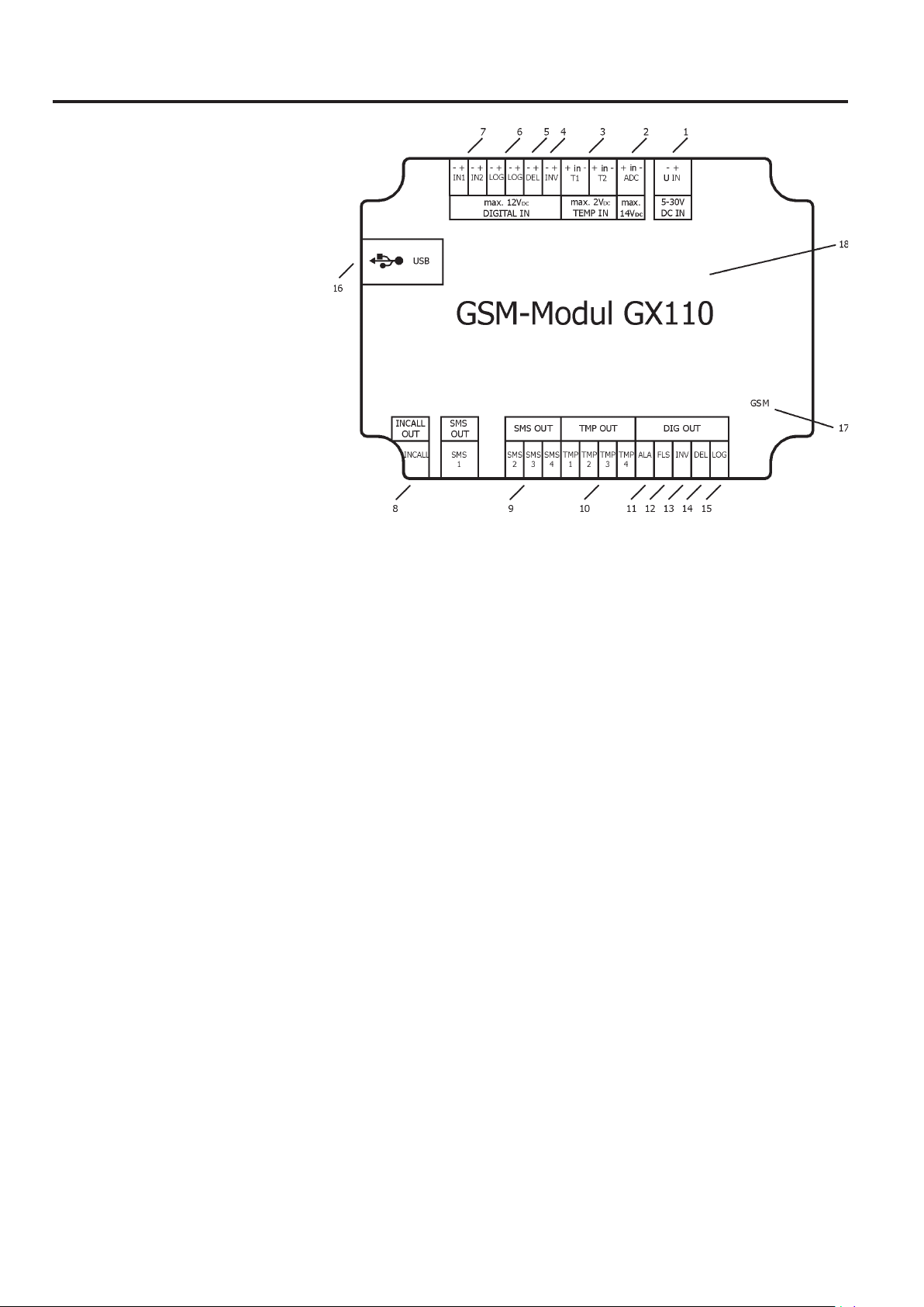
9. GSM Module Connections
1 Operating voltage connection
2 Analogue input „ADC“
3 Temperature sensor input „T1“ and „T2“
4 Digital input „INV“
5 Digital input „DEL“
6 Two digital inputs „LOG“
7 Two digital inputs „IN1“ and „IN2“
8 „Incall“ output
9 „SMS1“ to „SMS4“ output
10 „TMP1“ to „TMP4“ output
11 Output „ALA“
12 Output „FLS“ (no function)
13 Output „INV“
14 Output „DEL“
15 Output „LOG“
16 USB Connection
17 LED-display for GSM function
18 Connection for GSM aerial
Description of the Connections:
1 Connection for the operating voltage of 5 to 30 V/DC. Minus/- is connected to the left screw terminal and Plus/+ to the right terminal. Never
connect a higher voltage and always observe polarity!
2 Connection for the analogue input to measure a voltage of 0 to 14 V/DC. The input signal is connected to the centre screw terminal and the
Minus/- to the right terminal. 4 V/DC are applied to the left terminal.
3 Connection for both temperature sensors (Conrad item no. 198896): Plus/+ (white) is connected to the left screw terminal, the signal (red)
to the centre and Minus/- (black) to the right screw terminal.
Inputs (see figure 1, items 4 to 7):
Minus/- is connected to the left screw terminal and Plus/+ to the right terminal.
Figure 1
Observe the maximum input voltage of 12 V/DC at the optocoupler inputs (as of approx. 2.5 V/DC, the digital input signal is recognised
as „High“).
4 Connection for the digital inverter input („INV“)
5 Connection for the digital delay input („DEL“)
6 Connection for the two digital logic inputs („LOG“)
7 Connection for the two digital optocoupler inputs („IN1“/„IN2")
9
Page 10
Outputs (see figure 1, items 8 to 15):
8 Connection of the „INCALL“ output
9 Connection of the four outputs „SMS1“ to „SMS4“
10 Connection of the four temperature outputs „TMP1“ to „TMP4“
11 Connection of the alarm output „ALA“
12 Output „FLS“ (no function)
13 Connection of the inverter output „INV“
14 Connection of the delay output „DEL“
15 Connection of the logic output „LOG“
16 USB Port: The GSM module is connected to a free USB port of your computer via this connection with the included mini USB cable.
17 LED-display for GSM function: Once the GSM switching module has logged on to the GSM network, this LED flashes briefly about every
A relay is already installed to the „INCALL“ output (see figure 1, item 8) and the output „SMS1“; it can be used to switch 8 A at
250 V/AC or 30 V/DC.
Minus/- is connected to the left screw terminal and Plus/+ to the right terminal.
A relay (Conrad item no. 502892) or the relay PCB (Conrad item no. 585498) can be directly connected to the screw terminals.
Red LEDs are applied to all outputs. The LEDs light up once an output is activated and thus serve as status LEDs.
3 seconds.
18 Connection for GSM aerial
When the module no longer reacts (e.g. at strong EMC impulses, electrostatic discharge, etc.), the module must be disconnected from
the operating voltage and reconnected.
10
Page 11

10. Required Steps and Information for Commissioning
Important!
To take the GSM module into operation properly, the following steps must be performed strictly in the indicated order. Non-observance
may lead to functions not being warranted, configuration being impossible and/or the SIM card being locked by the GSM module.
a) Software Installation
Before taking up any work at the GSM module, you have to install the control software and the required drivers on your computer. To do so
proceed as follows:
• Place the CD in the appropriate drive of your computer. If auto start is activated on your computer, the installation will start from CD automatically
(programme „setup.bat“).
• If auto start is not activated, open the CD’s main directory and start the file „setup.bat“ by double-clicking (but not „setup.exe“).
• Follow the instructions on the screen.
• Once the control software is installed on your computer, the required drivers must be installed.
• To install the COM port driver („CP210xVCPInstaller.exe“), observe the notes on your screen.
The current driver versions are available online at www.silabs.com.
• After successful installation, close the control software again.
b) SIM Card Configuration
Proceed as follows to configure the SIM card:
• Insert the SIM card intended for the GSM module in any SIM lock-free mobile phone.
• Check the SIM card PIN according to the provider information. The PIN must have four digits and no spaces. If necessary, generate a new PIN
• Activate PIN query on the SIM card (PIN query is active if the mobile phone asks for the PIN after activation).
• Save the changes on the SIM card.
• Try out the reception quality with your mobile phone (usually displayed on the mobile phone). Find the best reception quality at the site where
To be able to configure the GSM module via the software later, the intended SIM card must be configured before initial use. For this,
you require a mobile phone without „SIM lock“. For configuration, observe the notes of the SIM card and the operating instructions of
your mobile phone.
and write it down.
the GSM aerial is to be placed and mark this position. The GSM aerial installation site should be as far as possible (within a distance of approx.
2.5 meters) from the installation site of the GSM module and enable interference-free reception with high field strength.
Radio network field strengths like for mobile phones may often be subject to extreme fluctuations due to external influences like
weather or sources of interference. For secure function of the GSM module, we therefore recommend choosing a site with the highest
field strength for the GSM aerial.
• Then remove your SIM card from the mobile phone again.
11
Page 12

c) General Settings of the Control Software
Use the button „D/E“ to switch the program language between German and English in the control software. The help file is opened in the
corresponding language.
Click the button „General Settings“. An interface appears for entering the SIM card’s PIN number, the desired phone numbers (PHONE) and
email addresses (MAIL). Also observe the notes and figures in the chapter „Initial Commissioning of the GSM Module“.
d) General Information on Text Messages
The phone number must be transmitted so that the module can „see“ who called or sent an SMS! Refer to the manual of your mobile phone to
see how to activate this function.
Contact your provider for the current prices and settings.
You may enter up to 12 phone numbers in „Phone“. You need to enter all phone numbers from which the module can be called or receive a text
message and to which the module is to be able to send a text message. The phone numbers should be entered in international format, e.g. as
„+491701234567“.
To check the format in which your phone number arrives, call the module and check the status display in the software. When calling the module
and sending a text message to the GSM module, the phone’s number must be transmitted. Phone numbers are limited to 16 digits. For a better
overview, you may enter any name for the phone number that is then displayed when selecting a phone number in the software.
e) SMS Service
In „Communication“, an SMS can be generated and sent out in the „SMS Service“. For this, the GSM module must be activated and logged on
to the GSM network.
The message text is limited to 160 digits. Umlauts (ä, ö, ü) cannot be entered.
Click „SMS Service“ in „Communication“ and enter the SMS text. The button „Send SMS“ shows how many characters are left of the 160. Enter
your mobile phone number below. Now push the button „Send SMS“ in current operation. The module sends an SMS with this text to your mobile
phone.
If an SMS from the GSM module does not arrive, the reason may be too little credit on your prepaid card or a wrong phone number may be
indicated.
f) General Information on Email
The Email SSL encryption must be deactivated.
GPRS and SMTP must be set up in „General Settings“ for sending out emails.
GPRS also must be released on the SIM card.
GPRS
The email data are sent to your provider via a data connection (not via a text message, etc.). For this, your SIM card establishes a GPRS
connection to your provider that assigns an IP address to the module. The set port can then be opened and SMTP activated.
SMTP
Then the module logs on to your mail provider using your email address and loggs in with your password to send an email for you. You are
generally the dispatcher of this email.
Depending on the provider, the email services may cause additional costs.
Generally, the following rule applies: If your provider or the GSM network does not entirely support the features „Sending an email“, the
services are not available in spite of the configuration settings being activated.
Contact your provider for the current prices and settings.
12
Page 13

g) Email with SMTP and GPRS
For sending emails, you have to indicate the GPRS settings of the provider of the inserted SIM card. If you indicate your provider in „SIM“, the
right GPRS connection and IP address are set automatically. If your desired setting is not among these, enter it at „other providers“.
The SMTP mail outbox must be entered in „SMTP“ (e.g. smtp.web.de). Additionally, the port number must be entered. Most freemail providers
require port number 25 to be entered.
Enter your email address and the associated password of your email address in the lower part of the „SMTP“ area. This password, with which
you log on to your mail provider as well, must not be longer than 15 digits and is only displayed encrypted.
You can enter up to 4 email addresses („MAIL“) in „General Settings“ (e.g. max.mustermann@conrad.de). You have to enter all email addresses
to which the GSM module is supposed to send an email. Email addresses are limited to 35 digits. For a better overview, you may enter any name
for the email address that is then displayed when selecting email addresses in the software.
Attention!
The GSM module is an autonomously working alarm notification device. Wrong settings or connections can cause undesired SMS to
be sent and possibly considerable costs! Also consider that international sending of messages or commands will cause further
additional costs for your mobile phone as well as for the SIM card inserted in the GSM module.
Never enter the phone number that belongs to the SIM card that is inserted in the module in the control software! This may cause the
module to send an SMS to itself during switching. Once this self-sent SMS is received, another answer will be generated, etc.! This
„endless loop“ may cause considerable costs!
Ensure good, operationally safe installation. Avoid loose contacts. Sensible threshold values should be set for sensor input and
control. Temperature thresholds like „switching on the heating at 20 °C and off at 21 °C“ may cause frequent and undesired switching
processes and sending of SMS messages.
Generally, the GSM module can monitor all inputs (sensors) at the same time and indicate their changes. Commands from the outside
can be processed at the same time. The GSM module processes all events in the order in which they occurred.
This GSM module can be used to send a switching command to another GSM module. In this case, the second device (message
receiver) must not have return answer activated! Connect the computer initially, try out the desired function and monitor all messages
in the software’s „STATUS“ display!
13
Page 14

11. Initial Commissioning of the GSM Module (Test Configuration)
First commissioning requires an operating voltage, aerial, USB cable and a SIM card.
Observe the following notes in the order as indicated:
• Open the GSM module’s casing.
• Remove the three screws in the GSM module that attach the PCB.
• Carefully lift the PCB from the casing.
• Connect the connection cable of the supply voltage to the intended clamps
• Install the USB drivers and application software first with the CD.
• Connect the USB cable from the delivery to the GSM module and to a free
At initial commissioning, observe that the removed PCB is not short-circuited by metal or live parts. When connecting the operating
voltage, always ensure correct polarity. Avoid short circuits at the GSM module connections. If this is not observed, the GSM module
will be destroyed. In such cases, any warranty/guarantee will expire!
We recommend the easiest possible configuration for initial commissioning. For this reason, you should initially only enter the PIN and
a device designation. All other input options for your device configuration should only be performed after successful verification of the
basic configuration at a later time.
on the PCB in the correct polarity (see chapter 9, figure 1, item 1).
Important!
Do not switch on the supply voltage yet!
The SIM card must not be installed yet!
port of your running computer.
The computer recognises a new (virtual) COM port.
• Check which COM port was set up in your operating system’s device
manager.
If the COM port number specified for the GSM module is bigger
than 9 (.e.g. „COM10“, „COM11“.....), the COM port must be moved.
For this, open the device manager in your computer’s system
settings in „Properties / Connection Settings / More... / COM-Port
Number“ and determine a free COM port below COM10 for the
control software.
14
Page 15

• Switch on the supply voltage now.
• Start the GSM module control software on your computer. Select the COM port determined in
your operating system’s device manager in the software under „Communication“.
• Then click „Status“ and check whether a connection has been
established. The GSM module has to indicate that the „PINCODE“ is
not correct yet („PINCODE FALSCH! WARTE AUF DATEN“ =
„WRONG PINCODE ! WAITING FOR DATA...“).
• Now enter the „PINCODE“ in the control software under „General Settings“. Here you have to
enter the four-digit PIN of the inserted SIM card. The PIN query on the SIM card must be
activated (meaning when you insert the SIM card in a mobile phone and turn it on, the PIN
query must appear!).
• A device designation of up to 16 characters can be entered for the module. During each SMS,
the module sends out this name at the beginning of the message so that it can be recognised.
15
Page 16

• Send the change to the module in „Communication“ (click the button
„Send“).
• The message „All data transferred!“ must appear.
• Switch off the operating voltage again.
• The saved data is preserved in the module even after switching the
operating voltage off and on again.
• To permanently save the input in the control software on your computer,
click the button „Save“.
• Now insert the SIM card.
For this, push back and open the lock of the SIM card holder on the rear of the PCB.
Insert the SIM card with the contacts pointing down and the cut corner to the top.
Close and lock the holder again. The SIM card contacts must push on the PCB contacts
after folding in.
• Unwind the GSM aerial cable and connect the aerial to the aerial socket on the PCB (figure 1, item 18). The aerial plug must latch audibly.
• Switch on the operating voltage again. The green GSM-LED (figure 1, item 17) starts flashing shortly after this. The module now tries to log on
• Click the button „Status“ in the menu item „Communication“ of the control software to display the inputs and outputs of the GSM module. The
Always ensure that the SIM card folder lid has latched correctly and is thus
securely closed.
to the GSM network.
If the green LED flashes quickly „1 second on / 1 second off“, the GSM module is trying to log on to the GSM network. This flashing is
shown after transfer of new data from the computer to the GSM module as well because this causes a restart to be performed.
After successful logon, the green LED flashes slowly (short flash / approx. 3 seconds break).
GSM module has to log on to the GSM network (if this has not been done already) and indicate the condition of all inputs and outputs. Also
observe the further notes in chapter 12.
• After complete transfer of the new configuration to the GSM module, the GSM module will restart. Once the green GSM LED flashes slowly
(LED on for 1 second, then 3 seconds break), the status of all inputs and outputs can be displayed.
16
Page 17

• You can assign a password with which everyone sending the password can switch. This makes it possible to switch the 4 SMS outputs and
• For sending emails, you have to indicate the provider of the inserted SIM card. GPRS must be activated on the SIM card for sending and
Due to the great number of SIM cards and providers on the market, you may receive the message „Wrong pin code! Waiting for data“
in the status window in spite of the SIM PIN being set correctly and the configuration being transmitted correctly. In this case, take a
different provider’s card, perform the required changes to the configuration according to the instructions and test the GSM module
again.
If this does not work, use the contact information listed in item 1 of these operating instructions.
Attention!
Without inserted SIM card (or in case of a wrong PIN), the GSM module will enter programming mode.
If the PIN is incorrect, the SIM card will be locked after the third failed log-in attempt!
In both cases, the green LED next to the aerial connection will flash quickly (1 second on / 1 second off). A card locked by the GSM
module can only be unlocked in a SIM lock-free mobile phone with the super PIN (see SIM card documentation). Check the device
configuration and the SIM card inserted in the GSM module.
request an SMS response from any mobile phone. The password must not be longer than 8 digits (also see the example in the chapter „4 Text
Message Outputs“).
receiving of emails.
Your provider must support the feature „Sending email“. If this is not the case, this function will not be available even if they are
activated in the configuration settings.
If you indicate your provider here, the correct GPRS address is automatically indicated („internet.gprs“ for T-Mobile, „web.vodafone.de“ for
Vodafone D2, „internet.eplus.de“ for E-Plus and „internet“ for O2) and the IP-address. If your desired address and IP address are not among
these, enter it at „other providers“.
17
Page 18

12. General Information on the „Status“ Button
The module performs a reset and dials into the GSM network once a configuration has
been transferred to the GSM module. Once the green GSM LED flashes slowly (LED on
for 1 second, then 3 seconds break), the status of all inputs and outputs can be displayed
in „Communication“.
• For this, set the COM interface recognised in the device manager.
• Click the button „Status“ in the control software.
• Then a display similar to a response SMS appears (see chapter „Response“), which is
updated every second.
• If the GSM module has sent a message, the message „SMS sent“ or „EMAIL sent“
appears.
• If no reception is possible, „NO NET!“ is displayed.
In this case, check the receiver quality at the location of the GSM aerial with a mobile
phone. Also note that the GSM aerial should be attached as far away from the GSM
module as possible.
• If the GSM module is presently being called, „Call detected“ and the phone number
appear and the green GSM LED is permanently lit.
• If the GSM module has received an SMS, „SMS received“ appears: and the SMS content
is displayed for approx. one minute.
Important!
Generally, the GSM module only recognises changes that are pending for at least 250 milliseconds at the six digital inputs (IN1, IN2,
LOG, LOG, DEL, INV) or that are pending for at least one second at the analogue inputs (ADC, T1, T2).
If you have sent a new configuration to the GSM module, the GSM module will restart automatically. The GSM module takes about one
minute after restart before it can perform any changes to the sensors or commands. You have about one minute after restart to apply
a voltage without sending a text message and/or email.
The following information is displayed at the status request:
Display Control Software Meaning
T1 = 0C The temperature at temperature sensor 1 is 0 °C
T2 = 0C The temperature at temperature sensor 2 is 0 °C
TMP1-4 = L,L,L,L The control outputs „TMP1“ to „TMP4“ are off (L = low)
IN1-2 = L,L The control outputs „IN1“ to „IN2“ are open (L = low)
ADC = 75 mV 75 mV were measured at input „ADC“
INCALL = L The control input „INCALL“ is not active (L = low)
SMS1-4 = L,L,L,L The control outputs „SMS1“ to „SMS4“ are off (L = low)
LOGIC = L,L=L The control input „LOG“ is off (L = low)
DELAY = L The control input „DEL“ is off (L = low)
INVERT = L The control input „INV“ is off (L = low)
ALARM = L The control input „ALA“ is off (L = low)
BILDER = 0 No function/no meaning
PEGEL = 80% The reception level in the GSM network is 80 percent
18
The status request values indicated in the chapter are only examples to display the indicated values and may deviate depending on
progress of your configuration.
Page 19

The following values apply for the „Level“ display value:
Status indicator Bar display control software Meaning
0% 5 red bars no reception or not logged in
1 to 20% 1 red bar no reception
21 to 36% 1-2 green bars bad reception
37 to 56% 3 green bars minimum permissible reception strength
57 to 76% 4 green bars good reception
77 to 100% 5 green bars good to very good reception
13. Determination of Phone Numbers
You can store up to 12 phone numbers in the control software under „Phone“ in „General Settings“.
You need to enter all phone numbers from which the module can be called or receive a text
message and to which the module is to be able to send a text message.
The phone numbers should be entered in international format (e.g. +491701234567). Phone
numbers are limited to 16 digits.
• Enter the phone number of your mobile phone with which you want to call the GSM module or
be informed by the GSM module by SMS in the top line of the left column for test purposes.
• Now save all settings of the control software by pushing the button „Save“.
• Send the data to the GSM module by clicking the button „Send“. The message „All data has
been transmitted!“ must appear.
• Basic configuration is now complete. For further configuration and installation, we recommend
testing all functions before final assembly.
When calling the GSM module and sending an SMS to the GSM module, the mobile phone’s number must be transmitted.
The GSM module can inform up to 4 email addresses in addition to the phone number saved. They are input after selection of the
button „Mail“ according to the „Phone“ input.
The information stored in the column „Name“ serves only assignment of phone numbers in the control software. The names entered
can only be read on your computer and are not transmitted in GSM module messages.
19
Page 20

14. Response / Error Message
a) Response
The GSM module can send a response SMS stating the conditions of all inputs and outputs
(status display -> also see chapter „Status Button“).
For this, an SMS with the „text message text“ saved in the GSM module is sent to the GSM
module. The GSM module response is sent to the number that sent the SMS.
The message text must contain no more than 8 characters. Also observe capitalisation.
• Enter „Reply“ as message text in the control software at „Response / Error“.
• Select the phone number of your mobile phone (also see following chapter „Determination of
the Phone Numbers“).
• Send the new configuration back to the GSM module by clicking the button „Send“. The message
„All data has been transmitted!“ must appear.
• Send an SMS with the text „Reply“ to the GSM module after a status message is provided.
• The status window must display the incoming SMS with text and phone number.
• The response of the GSM module also must arrive on your mobile phone as an SMS in which
the status of all inputs and outputs is displayed (similar to the status window in the control
software).
Example:
You are sending an SMS to the GSM module with the text that is stored in the GSM module as „Response / Error Message“ (e.g. „Reply“). The
GSM module responds with, e.g.:
CONRAD GX110 T1=23C, T2=27C, TMP1-4=L,L,L,L, IN1-2=L,L, ADC=0mV, INCALL=L, SMS1-4=H,L,L,L, LOG=L, DEL=L, INV=L, ALARM=H,
BILDER=0, PEGEL=60% -ENDE-
The above message means that the temperature sensor has measured 23 °C at connection „T1“ and the sensor at connection „T2“ has
measured a temperature of 27 °C and that none of the 4 temperature outputs „TMP1“ to „TMP4“ has switched on.
Both optocoupler inputs „IN1“ and „IN2“ are „Low“, the input „ADC“ measures 0 mV, the output „INCALL“ has not been activated, the output
„SMS1“ is switched on and the outputs „SMS2“ to „SMS4“ are inactive.
The output „LOG“ is „Low“, the delay output „DEL“ is „Low“, the output „INV“ is „Low“, the output „ALA“ is active and the reception level is at 60%
(i.e. reception is good). The Message „BILDER=0“ has no function/meaning.
The status request values indicated in the chapter are only examples to display the indicated values and may deviate depending on
progress of your configuration or the measured values of the sensors connected.
b) Error Message
The GSM module can return an error message with a defined message text if it receives an unknown or wrong command (e.g. „ERROR“). This
makes sense for the fast detection of wrong input (e.g. in case of a typing error). The response is sent to the phone number that sent the SMS.
Example:
You send an SMS to the GSM module with the unknown command (e.g. RRRR). The GSM module responds with:
ERROR
20
Page 21
15. Installation and Configuration of the Outputs
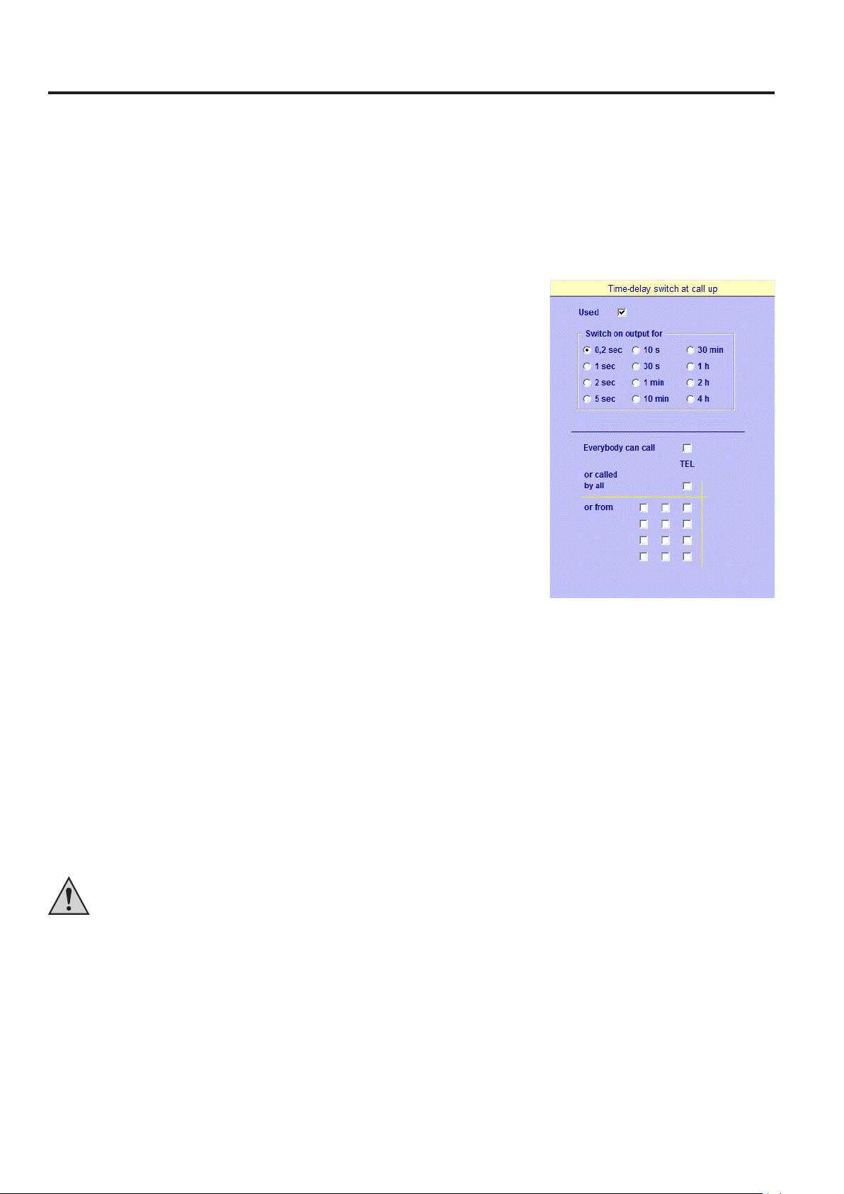
a) „INCALL“ Output
The „INCALL“ output switches on for a defined time when the GSM module is called. Because the GSM module does not pick up, this is free of
charge!
Just call the GSM module and let it ring a few times. Then the „INCALL“ output switches on for the time set in the control software and then off
again automatically.
This is ideal, e.g., for a garage door opener or front door light. The activation time can be set in 12 stages from 0.2 seconds to 4 hours.
Proceed as follows to use the „INCALL“ output:
• Enter the phone number of the phone with which you want to call in the top line of „Phone“ in
„General Settings“.
• The phone number must be entered in international format.
Wrong: 01701234567
Correct: +491701234567
• Click the checkbox „Used“ in „1 Incall Output“ so that the checkmark appears. The „INCALL“
output can now be configured.
• Click the switching duration „10 sec“ in „1 Incall output“.
• For a selection of phone numbers, choose one of the following options:
„Everyone can call“: The „INCALL“ output switches the connected relay for any call received.
„or called by all“: In this configuration, the GSM module can be controlled by any phone number
stored in the control software in „Phone“.
„or from“ (recommended for initial commissioning): The GSM module can only be controlled by
phone numbers selected by clicking them.
The boxes in the first, left column correspond to phone numbers 1 to 4 from top down; those in the second, medium column, correspond to
phone numbers 5 to 8 and those in the right column to phone numbers 9 to 12 as they were stored in the chapter „Determination of Phone
Numbers“.
• Finally, send the change to the GSM module again in „Communication“ (click button „Send“). The message „All data has been transferred!“
must appear.
• Now call the phone number of the SIM card inserted in the GSM module with your mobile phone. Let the phone ring a few times.
• The relay for the „INCALL“ output (figure 1, item 8) now has to activate and a red indicator LED has to show this.
• The relay must deactivate again after approx. 10 seconds, and the control LED goes out.
If the „INCALL“ output function was correct, this function can be freely used from now on. To control a function, connect a device to the
„INCALL“ relay contacts. For this, observe the maximum permissible voltages and currents in the technical data and the diagram note for
connection of a consumer by relay at the end of the operating instructions.
Attention!
If the control software is configured to „Everybody can call“, this output will activate at every call. This applies irrespective of whether
the phone number is included in the phone list or not.
Everyone who knows the phone number of the SIM card in the GSM module or calls it by accident (e.g. because he dials the wrong
number) will be able to control the GSM module! The module activates even if no phone number is transmitted. Therefore, we
recommend that you only select those phone numbers from your list that are allowed to activate this output.
21
Page 22

b) SMS Outputs „SMS1“ to „SMS4“
The outputs „SMS1“ to „SMS4“ can be activated or deactivated by sending an SMS to the GSM module. A relay is already connected to the
output „SMS1“. A relay (Conrad item no. 502892, not included in the delivery) or a relay PCB (Conrad item no. 585498, not included in the
delivery) can be directly connected to the remaining outputs. Every SMS output has its own indicator LED that visually displays the activation
process.
The relay switching contacts can be used to close or open electrical circuits. A separate message text can be entered for each of the 4 outputs.
For switching, send an SMS with the message text for the respective output with the appendix „=1“ for activation or „=0“ for deactivation (without
quotes).
Proceed as follows to configure the SMS outputs:
• Check „Assigned“ for „SMS1“ in the control software, „4 SMS Outputs“ for the output „SMS1“
• Enter the message text „Output1“.
• Select a phone number. The following options are available:
When sending SMS, always observe that the „Command texts“ from the mobile phone correspond precisely to the texts stored in the
control software or the GSM module. Capitalisation must be observed here. The message text must contain no more than 8 characters.
The command text must be followed by the command without any space (e.g. „=1“ for activate).
to be switched on.
Every output must be assigned its own „message or command text“ (e.g. „Output1“, „Output2“,
etc.). Selection of the desired phone numbers is determined in output 1 and is valid for all four
outputs.
„Sent from everyone“: The „SMS output“ switches the targeted output for any SMS received.
Attention!
Configuration „Sent from everyone“ in the control software means that the selected output will switch for any SMS with the correct
message text. This applies irrespective of whether the phone number is included in the phone list or not.
Everyone who knows the phone number of the SIM card in the GSM module or selects it by accident and sends the correct message
text, may control the GSM module! The module activates even if no phone number is transmitted. Therefore, we recommend that you
only select those phone numbers from your list that are allowed to activate this output.
„or sent from all“: In this configuration, the GSM module can be controlled by any phone number stored in the control software in „Phone“.
„or from“ (recommended for initial commissioning): The GSM module can only be controlled by phone numbers selected by clicking them. The
boxes in the first, left column correspond to phone numbers 1 to 4 from top down; those in the second, medium column, correspond to phone
numbers 5 to 8 and those in the right column to phone numbers 9 to 12.
• Finally, send the change to the module again in „Communication“ (click button „Send“). The message „All data has been transferred!“ must
appear.
• Now send an SMS to the phone number of the SIM card inserted in the GSM module with your mobile phone. Use the „message or command
text“ with the annex „=1“ that was previously entered in the control software or GSM module.
• Selecting „switch always if password sent“ means that the GSM module will always switch if the password in the text message is correct (and
the command text is sent along). You can save a password in the control software in „Communication“ (also see chapter 11, Initial Commissioning
of the GSM module)
22
Page 23

A response by SMS is only given to the phone numbers that have sent a correct command and are stored in the control software.
Example:
Test=1
The relay for SMS output 1 (figure 1, item 9) is switched on after receipt of the SMS. The indicator LED lights up.
This condition remains active until the SMS output 1 is deactivated again with a new SMS. For this, send an SMS with the following text:
Test=0
The relay for SMS output 1 (figure 1, item 9) is switched off after receipt of the SMS. The indicator LED goes out.
If the „SMS output 1“ function was correct, this function can be freely used from now on. To control a function, connect a device to the „SMS
output 1“ relay contacts. For this, observe the maximum permissible voltages and currents in the technical data and the diagram note for
connection of a consumer by relay at the end of the operating instructions.
A relay is already connected to the output „SMS1“.
The SMS outputs 2 to 4 (figure 1, item 9) work according to SMS output 1. No relays are connected to these outputs. At your own discretion,
the control voltage (approx. 4 V, max. 100 mA) can also directly affect other electronic circuits when the output is active. However, a relay
(Conrad item no. 502892) or the relay PCB (Conrad item no. 585498) can also be be directly connected to these outputs.
c) Temperature Outputs „TMP1“ to „TMP4“
Two temperature sensors (Conrad item no. 198896, not included in the delivery) can be connected
to the two temperature inputs „T1“ and „T2“ (figure 1, item 3). Plus/+ (white) is connected to the
left terminal, the signal (red) to the centre and Minus/- (black) to the right terminal. The sensor’s
temperature level can range between -40 °C to +125 °C.
If only a single temperature sensor is used, the input „T1“ must be selected.
If no sensor is connected, the middle input should be connected to the minus connection
(-), for 0 °C to be measured by it and issued.
The outputs „TMP1“ to „TMP4“ (figure 1, item 10) are logically linked with the temperature control.
A relay (Conrad item no. 502892, not included in the delivery) or a relay PCB (Conrad item no.
585498, not included in the delivery) can be directly connected to each of these outputs.
There are two different operating modes: Area measurement and differential measurement.
Area measurement:
You can set a MAX, MIN and a TARGET temperature value for both temperature sensors. The
TARGET value is the defined temperature for the control: If the MAX value is exceeded, output
„TMP1“ (for sensor „T1“) or „TMP3“ (for sensor „T2“) is activated automatically (e.g. for a ventilator)
until the temperature undercuts the TARGET value again.
If the MIN value is undercut, the output „TMP2“ (for sensor „T1“) or „TMP4“ (for sensor „T2“) is activated (e.g. for a heater) until the TARGET
value is exceeded again.
This generates a hysteresis that prevents the outputs from switching on and off in turn all the time.
Example:
If you set the temperature value „MIN“ to 10 °C, the „TARGET“ temperature value to 20 °C and the „MAX“ temperature value to 25 °C), the
output „TMP1“ is switched on when exceeding the MAX value (26 °C) and switched off when reaching the TARGET value (20 °C). When the
temperature drops below the MIN value (9 °C), the output „TMP2“ is switched on and only switched off again when the target temperature
(20 °C) is reached.
23
Page 24

Differential measurement:
In this case, only the temperature difference is controlled (e.g. forward/backward flow of a heater), meaning there is no TARGET temperature.
Once the difference (T2-T1) exceeds the MAX value, the output „TMP1“ activates; if the difference (T2-T1) undercuts the MIN value, the output
„TMP2“ activates. „TMP1“ and „TMP2“ are switched off once the temperature difference is again within the MIN and MAX range. „TMP3“ and
„TMP4“ are not switched.
Example:
Input „Min = 20 °C“ means that the output „TMP2“ is activated if there is a difference of less/equal to 20 °C between the sensor „T2“ and „T1“.
Input „Max = 50 °C“ means that the output „TMP1“ is activated if there is a difference of more/equal to 50 °C between the sensor „T2“ and „T1“.
If a temperature of +65 °C is measured at sensor T2 and +15 °C at sensor T1, the output „TMP1“ switches on.
If a temperature of +65 °C is measured at sensor T2 and +45 °C at sensor T1, the output „TMP2“ switches on.
Between the two corner values +15 to +45 °C, the outputs „TMP1“ and „TMP2“ remain inactive.
Difference measurement means that the outputs „TMP3“ and „TMP4“ are not switched.
This temperature control can additionally return a message: When exceeding the MAX temperature or undercutting the MIN temperature, the
GSM module can return an automatically generated SMS of an email with the message text „ALARM TEMP“.
Important!
Generally, the GSM module only indicates changes that persist for at least one second or undercut/exceed the threshold value.
If you have sent a new configuration to the GSM module, the GSM module will restart automatically. The GSM module takes only one
minute after restart before it can perform any changes to the sensors or commands. This waiting time must be strictly observed! You
have about one minute after restart to apply a voltage without sending a text message and/or email.
To verify the temperature outputs, proceed as follows:
Apply direct voltage between 1 and 2 V (e.g. a 1.5 V dry battery) to input „T1“.
Never apply any voltage exceeding 2 V!
Observe correct polarity. Connect the battery’s minus pole to the
right terminal „-“ and the plus pole to the middle terminal „T1“.
• The control software status window must display a temperature in excess of 50 °C and the message „SMS sent“ must appear; the message
text „Alarm Temp1 = xxC“ must be sent to the mobile phone by SMS.
• Choose the features applicable for your configuration in the control software under „4 temperature outputs“.
• Determine who is to be informed how in case of a message as described in the previous examples (e.g. „output INCALL“).
• Send the new configuration to the GSM module by clicking the button „Send“.
To control devices (e.g. a ventilator), connect the respective temperature outputs of the GSM module to the external devices. For this,
connect the temperature outputs under your own discretion (observe permissible operating voltages, see „Technical Data“) or install
additional relays (Conrad item no. 502892) or relay PCBs (Conrad item no. 585498). Also observe the notes in these operating
instructions, chapter 14 „Temperature Inputs T1 and T2“.
If only a single temperature sensor is connected, this sensor must be connected to input „T1“. If two temperature sensors are connected,
the threshold value excesses of „T1“ and „T2“ are indicated by SMS.
24
Page 25

d) Alarm Output „ALA“
The alarm output „ALA“ (figure 1, item 11) can be activated from any input, i.e. the output is
always switched on when a text message or email was sent. It can therefore be triggered by the
temperature control, the optocouplers, the ADC, the logic, the delay and the inverter.
A relay (Conrad item no. 502892, not included in the delivery) or a relay PCB (Conrad item no.
585498, not included in the delivery) can be directly connected to the output. The output has an
indicator LED that visually displays the switching process.
• Click the checkbox „Used“ in „1 Alarm Output“ and select, e.g., 1 minute under „Activate on
for“.
• If a signal sends a text message or email to an activated input now, this output is switched on
for one minute and automatically switched off again after one minute.
The alarm output „ALA“ is, e.g., intended for an alarm buzzer or flash light lamp with a duration
adjustable from 0.2 seconds to 4 hours (in 12 steps).
e) Output „FLS“
This output has no function.
f) Inverter Output „INV“
The output „INV“ (figure 1, item 13) is inverted at every pulse at the input „INV“ (figure 1, item 4).
When switching the output on and/or off because of such an impulse, a text message or email
can be sent.
A relay (Conrad item no. 502892, not included in the delivery) or a relay PCB (Conrad item no.
585498, not included in the delivery) can be directly connected to the output. The output has an
indicator LED that visually displays the switching process.
A direct voltage from 0 to 12 V/DC can be connected to the input „INV“ (figure 1, item 4). The
minus pole is connected to the mark on the left; the plus pole is connected to the right of it. As of
about 2.5 V, „HIGH“ is logically recognised, below 1 V, „LOW“ is logically recognised.
This inverter turns every button input into the on/off function of a switch by inverting the output
„INV“ at every rising flank at the input.
• Click the checkbox „Used“ in „1 Inverter Output“. The inverter is activated.
• If you not activate „Alarm at switching on“ additionally, for example, an additional text message
and/or email is sent each time you switch on the output „INV“ by an impulse at the input.
This principle is used in power source switches that are used when several switches control a
joint consumer as in the case of several light buttons in a hallway.
25
Page 26

g) Delay Output „DEL“
The output „DEL“ (figure 1, item 14) can switch on and/or off with an input „DEL“ (figure 1, item
5) when the input is switched. Additionally, a text message and an email can be sent when the
input signal changes and the switching delay is activated.
A relay (Conrad item no. 502892, not included in the delivery) or a relay PCB (Conrad item no.
585498, not included in the delivery) can be directly connected to the output. The output has an
indicator LED that visually displays the switching process.
A direct voltage from 0 to 12 V/DC can be connected to the input „DEL“ (figure 1, item 5). The
minus pole is connected to the mark on the left; the plus pole is connected to the right of it. As of
about 2.5 V, „HIGH“ is logically recognised, below 1 V, „LOW“ is logically recognised.
• Click the checkbox „Used“ in „1 Delay Output“.
• Now select the period in „Switching on delay“ after which the output is to be activated or
deactivated.
• Select the Activation and/or deactivation delay. The switching delay is now active.
• If you now select a text message and/or email in „Message“, a text message and/or email is
sent additionally every time the input switches.
Example:
Only activation delay is activated and set to one hour.
If the associated input is „HIGH“ now, a text message is sent at once and you have one hour’s time to remove the „error“ (e.g. to reactivate the
alarm system again).
If the „error“ is not removed (i.e. if the input is not set to „LOW“ again within the set time), the output to which, e.g, a buzzer is connected, is
activated after one hour.
When switching off the input, the output is switched at once in this example without sending any text message or email.
An activation delay may be used for delayed activation of alarm system (so that there is still time to leave the room).
Deactivation delays are found, e.g. at fan lag. This deactivation delay may also be used, e.g., for staircase lighting: it switches on right after the
button is pushed, and off again after an adjustable time (for this, a button must be connected to the input that turns „HIGH“ when the button is
pushed and „LOW“ again when it is released).
The activation and deactivation delays can also be activated at the same time. Then activation and deactivation both is done with a delay.
If a text message is sent only after delayed switching, a voltage may be switched through with this output and connected to one of the two
optocouple inputs „IN1“ or „IN2“.
26
Page 27

h) Logic Output „LOG“
This is the output „LOG“ (figure 1, item 15) that can be logically linked to the two inputs AND,
NAND, OR, NOR or EXOR for activation and deactivation.
A relay (Conrad item no. 502892, not included in the delivery) or a relay PCB (Conrad item no.
585498, not included in the delivery) can be directly connected to the output. The output has an
indicator LED that visually displays the switching process.
A direct voltage from 0 to 12 V/DC can be connected to both inputs „LOG“ (figure 1, item 6). The
minus pole is connected to the mark on the left; the plus pole is connected to the right of them. As
of about 2.5 V, „HIGH“ is logically recognised, below 1 V, „LOW“ is logically recognised.
• Click the checkbox „Used“ in „1 Logic Output“.
• Now select the link of the two inputs under „Input logic“. This activates the logic circuit.
• If you now select a text message and/or email in „Message“, a text message and/or email is
sent additionally every time the output activates.
Input AND NAND OR NOR EXOR
00 01010
01 01101
10 01101
11 10100
Example:
The AND link is selected.
The output only becomes „HIGH“ when a level is applied to the two inputs.
Additionally, a text message or an email can be sent when switching on the output.
27
Page 28

16. Installation and Configuration of the Inputs
Note:
There is a separate 10-minute-lockout for each of the inputs: If a text message has been delivered because of a signal at the input,
then this input is blocked for 10 minutes. This is regardless of what happens at this input - it is sent no text message before the end of
10 minutes!
Each input has its own 10-minute-lockout. That means, when an alarm occurs on another input, you will receive a text message.
a) Inputs „IN1“ and „IN2“ (2 Optocouplers)
The inputs „IN1“ and „IN2“ (figure 1, item 7) can send a text message and/or email in case of a signal change. The SMS text can be determined
in the configuration software.
If there is no external voltage at the inputs „IN1“ and „IN2“, e.g. supplied by a smoke detector, the inputs are in the switching condition „LOW“. If
an external voltage between 3 - 12 V/DC is connected, the inputs are set to the switching condition „HIGH“.
The devices connected to inputs „IN1“ and „IN2“ (e.g. a smoke detector) must deliver a „signal voltage“ of 3 - 12 V/DC in case of alarm.
Otherwise, the devices must be connected to an „auxiliary voltage“.
No output can be switched, but only the alarm output. The input signal change must be present for at least 250 milliseconds before it
is recognised.
Since the GSM module will only check all changes after approx. one minute after restart, you have to delay verification of correct
function of this circuit by this time. If, e.g., motion detectors are connected to the inputs as a test, we recommend connecting the
devices again only after one minute.
Proceed as follows for configuration:
• Check „Assigned“ for „Input 1“ in the control software under „2 Optocouplers inputs“ for the
input to be switched on.
• Enter a designation for the input 1 in „Message“ (e.g. „DIGITAL1“).
• Activate „Message if input is high“.
• Select (as described in detail in the previous chapters) the phone number of your mobile
phone.
• Send the input to the GSM module in „Communication“ (click button „Send“).
• The message „All data has been transferred!“ must appear.
• If you want to permanently keep these changes, save them in the control software as well
(button „Save“).
• Click the „Status“ in the control software under „Communication“.
• The GSM module has to log on to the network and indicate the condition of all inputs and
outputs.
• Connect a direct voltage between 3 and 12 V/DC after a waiting time of at least
1 minute at the „IN1“ (minus at the left terminal and the plus pole at the right
terminal).
• Once the voltage was applied, the control software must recognise „IN1“ as
„HIGH“.
• Then the output „SMS sent“ must appear and the SMS with the entered message
text (alarm IN1: „DIGITAL1“) must be received by your mobile phone.
Only one text message/email is sent. Only when the input was „LOW“ again and then becomes „HIGH“ again, another text message is sent. This
applies accordingly for the reverse case in which „Message if input is low“ hasbeen set.
28
Page 29

b) ADC Input
The ADC input can measure voltages from 0 to 14 V/DC.
The voltage to be measured is connected to the middle input (ADC) and the right input (minus).
An auxiliary voltage of +4 V/DC is output at the left terminal (+).
The GSM module can trigger a message by SMS above and below a voltage set. The threshold
value is entered in millivolt (mV).
Proceed as follows for configuration:
• Open the control software.
• Enter a message text in „1 ADC input“.
• Determine the threshold value, e.g. 1.0 V (1.0 V = 1000 mV).
• Check „is higher“.
• Select (as already described several times) the phone number of your mobile phone (check).
• Send the changes to the GSM module under „Communication“ by clicking the button „Send“.
• Wait for at least one minute, then apply a voltage between 1 and 14 V/DC to the
ADC input terminals (figure 1, item 2) (e.g. from a 1.5 V dry battery).
• Now you can trace the status in the control software under „Communication“.
• The display must change to the voltage value applied to the input behind „ADC“.
• Once the voltage exceeds 1.0 V (value above „1000“), the message „SMS sent“ must appear; the entered message text must be sent to the
Always observe correct polarity. Never apply any voltage exceeding
14 Volt!
mobile phone by SMS.
This ADC is meant,e.g. for an analogue fill level indicator; the module can then issue a warning message before the supply container becomes
empty or flows over. You may top up the container to the desired volume for threshold value determination, read the output value in the status
and enter it into the software as a threshold.
Important!
Generally, the GSM module only indicates changes that persist for at least one second or undercut/exceed the threshold value.
If you have sent a new configuration to the GSM module, the GSM module will restart automatically. The GSM module takes about one
minute after restart before it can perform any changes to the sensors or commands. This waiting time must be strictly observed! You
have about one minute after restart to apply a voltage without sending a text message and/or email.
29
Page 30

17. SMS Service
With this GSM module, you can easily write and send an SMS as on a
mobile phone.
The SMS is then sent by the GSM module via the inserted SIM card.
Therefore, also observe the costs resulting from sending SMS.
Once the GSM module has dialled into the GSM network, you can generate an SMS text with the button „SMS Service“ in „Communication“.
The SMS may have up to 160 characters. The button „Send SMS“ shows
the remaining number of possible characters.
Use the button „Send SMS“ to send the SMS to the phone number
previously entered in „Phone Number“.
Important!
Umlauts (ä, ö, ü) cannot be entered.
30
Page 31

18. Final Assembly
To install the GSM aerial, remove the protective foil from
the GSM aerial. Glue the aerial to the assembly site you
have already tested for good, interference-free reception
as described in chapter „Configuration of the SIM-Card“.
Place and attach the aerial cable to the place where the
GMS module is to be installed (e.g. with cable ties).
Install the empty GSM module casing with suitable screws
(not included in the delivery) to the holes already present
(where the lid is screwed on).
Before final assembly, first get familiar with all
functions and try out the device in all applications
you want to install.
Attention!
Before drilling, make sure that there are no building installations at the drill sites. Damage to gas, electricity, water and wastewater
pipes may lead to mortal danger or property damage!
Do not install the device right next to radiators or devices that may cause interferences (e.g. motors, switching cabinets, etc.). Outdoor installation
must be performed at a site protected from splashing water and protected from solar irradiation all day
Break the required holes for the cable infeed for operating voltage, sensors and devices to be connected to the GSM module out of the casing.
Install the GSM module PCB in the casing and attach all cables of the operating voltage, sensors and devices to be connected to the GSM
module. Observe the required connection polarity and firm seat of the cables.
Now install the cables for the supply voltage and the cables of the devices or sensors to be connected to the GSM module. The connection
cables are guided through the closing plugs. The closing plugs are then installed in the casing.
Place the cables with suitable cable ties or cable clamps (not included in the delivery) to prevent inadvertent pulling out from the connection
casing.
After installation of all cables, you can take the GSM module into operation and try out all functions. If everything works correctly, close the casing
with the lid.
Observe suitable cable cross-sections and a cable type that matches the application case (in particular if the mains voltage (230 V/AC)
is to be switched).
The module may only be commissioned after it has been installed contact-free in a casing. Prior to commissioning the assembly,
check whether it is suited to the intended application!
In case of doubt, you must contact an expert or the manufacturer!
31
Page 32

19. Troubleshooting
a) Possible Errors during Communication
Drivers not installed:
• Re-install „CP210xVCPInstaller.exe“ on the CD in directory „MCU“
Drivers not installed correctly:
• Uninstall and reinstall drivers
COM-Port above COM10:
• Move COM port: Go to Properties / Connection Settings / More... / COM port number in the device manager and find a free COM-port below
COM10
Software message „ERROR: No answer received from module!“:
• Check USB connection between the module and PC or check operating voltage
• Select correct COM port in the software and click „Status“ again
• Operating voltage missing or too low
b) Possible Errors during Logon
SIM card locked:
• Insert SIM card in a mobile phone and unlock with the PUK
No four-digit PIN code:
• Insert SIM card in a mobile phone, activate PIN query and set a four-digit code
Display „Level = 0“ and signal strength only shows red bars:
• Not logged on to the GSM network yet; wait until the GSM module has logged on.
• Move the aerial if required.
c) Possible Errors during Response
No phone number displayed in the status:
• Activate caller ID transmission in the mobile phone
SMS arrives but response is not sent:
• Enter wrong phone number
• Caller ID transmission deactivated
• SMS sent from another mobile phone or configuration not transmitted
• Capitalisation not observed
• Not enough credit on the prepaid card
32
Page 33

d) Possible Errors during „INCALL“
Message „Participant not available“
• Module has not logged on to the GSM network yet: Wait briefly until the module has logged on or move the aerial to another place
No phone number displayed in the status
• Activate caller ID transmission in the mobile phone
Message „No caller authorisation“
• Enter wrong phone number
• Caller ID transmission deactivated
• Called from another mobile phone or configuration not transmitted
e) Possible Errors of TEMP1-4
Signal is not recognised
• Duration too short: Signal must be present for at least about one second before it is recognised.
Signal is recognised, status also indicates, e.g. T1=86C, but does not send SMS
• Signal was applied right after switching on: The module will only check for changes at the inputs after approx. one minute. Therefore disconnect
the signal, wait for a moment and connect it again.
• Not enough credit on the prepaid card
f) Possible Errors of IN1 and IN2
Signal is not recognised, status does not indicate IN1,IN2=H,L
• Wrong voltage: The signal must be a direct voltage of at least 3 V and most 12 V/DC
• Duration too short: Signal must be present for at least about one second before it is recognised.
• Signal incorrectly connected: Connect minus to mark „-“ and plus to the right
SMS is only sent after the voltage is removed again
• „Message when input LOW“ is active in the software.
Signal is recognised, status also indicates IN1,IN2=H,L, but does not send SMS
• Signal was applied right after switching on: The module will only check for changes at the inputs after approx. one minute. Therefore disconnect
the signal, wait for a moment and connect it again.
• Not enough credit on the prepaid card
g) Possible Errors of ADC
Signal is not recognised
• Duration too short: Signal must be present for at least about one second before it is recognised.
Signal is recognised, status also indicates, e.g. ADC = 1,500 mV, but does not send SMS
• Signal was applied right after switching on: The module will only check for changes at the inputs after approx. one minute. Therefore disconnect
the signal, wait for a moment and connect it again.
• Not enough credit on the prepaid card
33
Page 34

h) Possible Errors of SMS1
No phone number displayed in the status
• Activate caller ID transmission in the mobile phone
SMS arrives but SMS1 is not switched
• Wrong phone number entered
• Caller ID transmission deactivated
• Called from another mobile phone or configuration not transmitted
• Capitalisation not observed
i) Possible Errors of the SMS Service
SMS does not arrive
• Not enough credit on the prepaid card
• Wrong phone number entered
34
Page 35

20. Circuit Example
1 Relay contacts (e.g. „INCALL“ output)
2 Supply voltage (e.g. solar battery)
3 Consumers (e.g. lighting)
21. Maintenance and Repair
The GSM module is maintenance- and care-free. Connect the manufacturer if any repairs are necessary.
22. Disposal
Electronic devices are recyclable waste and must not be disposed of in the household waste!
At the end of its service life, dispose of the product according to the relevant statutory regulations.
23. Declaration of Conformity (DOC)
We, Conrad Electronic SE, Klaus-Conrad-Straße 1, D-92240 Hirschau, hereby declare that this product complies with the fundamental requirements
and the other relevant regulations of the directive 1999/5/EC.
The declaration of conformity for this product is available at www.conrad.com.
35
Page 36

24. Technical Data
GSM
Quad GSM-Band......................................................... 850, 900, 1800 1900 MHz
SIM card type .............................................................. 3 V SIM card
GSM module
Operating voltage ........................................................ 5 to 30 V/DC
Required power supply................................................ min. 1,000 mA
Power consumption (at 12 V) ...................................... stand-by: max. 30 mA; with 14 relays: max. 1,000 mA
Input Values
IN1, IN2, LOG, DEL, INV ............................................ 0 - 12 V, logical L at 0 V, logical H at approx. 2.5 V to 12 V, approx. 5 mA at 12 V
ADC ............................................................................ 0 - 14 V, resolution 14 mV; supply voltage 4 V
T1 and T2 .................................................................... 0 - 2 V, supply voltage 4 V, temperature sensor TC1047A
Output Values
SMS2 to LOG .............................................................. 4 V, max. 50 mA
Relay INCALL and SMS1
Rated voltage of the relay coil ..................................... 5 V
Switching current ......................................................... max. 10 A
Switching voltage ........................................................ max. 150 V/DC, 400 V/AC
Rated load ................................................................... 30 V/DC, 5 A or 250 V/AC, 3 A
Casing
Protection type ............................................................ IP54
Temperature range ...................................................... -20 °C to +75 °C
Dimensions
Circuit board (L x W x H ) ............................................ 120 x 72 x 17 mm
Casing (L x W x H ) ..................................................... 130 x 94 x 57 mm
Total weight ................................................................. approx. 300 g
Accessories (not part of the delivery, can be ordered separately)
Matching relay for all outputs ........................................................... Conrad item no. 502892
Matching relay PCB for all outputs ...................................................Conrad item no. 585498
Matching temperature sensor for the inputs T1 and T2 .................... Conrad item no. 198896
Matching replacement aerial ............................................................ Conrad item no. 199399
36
Page 37

373839
Page 38

Page 39

Page 40

http://www.conrad.com
Legal Notice
This is a publication by Conrad Electronic SE, Klaus-Conrad-Str. 1, D-92240 Hirschau (www.conrad.com).
All rights including translation reserved. Reproduction by any method, e.g. photocopy, microfilming, or the capture in electronic data processing
systems require the prior written approval by the editor. Reprinting, also in part, is prohibited. This publication represent the technical status
at the time of printing.
© Copyright 2016 by Conrad Electronic SE. V2_0216_01_DT
 Loading...