

Page 1

Version 01/07
FAZ 3000-TF-2
Wireless door/window
detector
Item no. 75 03 35
OPERATING INSTRUCTIONS
This user manual belongs to this product. It contains important information
specific to its operation and handling. Please bear this in mind when
passing on the product to a third party.
Therefore keep this user manual for future reference!
A contents list can be found in the table of contents on page 2.
http://www.conrad.com
Imprint
These operating instructions are published by Conrad Electronic SE, Klaus-ConradStr. 1, D-92240 Hirschau/Germany.
All rights reserved.
No reproduction (including translation) is permitted in whole or part e.g. photocopying,
microfilming or storage in electronic data processing equipment, without the express
written consent of the publisher.
The operating instructions reflect the current technical specifications at the time of
print. We reserve the right to change the technical or physical specifications.
© Copyright 2007 by Conrad Electronic SE. Printed in Germany.
100%
recycled
paper.
Bleached
without
chlorine.
Page 2

2
Table of contents
Page
1. Introduction .......................................................................................... 3
2. Prescribed use ..................................................................................... 4
3. Scope of delivery ................................................................................ 4
4. Explanation of icons ............................................................................ 5
5. Safety instructions .............................................................................. 5
a) General information ....................................................................... 5
b) Batteries and rechargeable batteries ............................................ 6
6. Features and functions ....................................................................... 7
7. Installation ............................................................................................ 8
a) Installation notes ............................................................................ 8
b) Installing the door/window detector ............................................. 11
8. Registering the door/window detector with the alarm base station .. 14
9. Open the door/window detector’s casing, replacing the batteries .... 19
10. Explanation of ‘Internal/external sensor’ and ‘closure group’ .......... 21
a) Internal/external sensor ............................................................... 21
b) Closure group ............................................................................... 22
11. Maintenance and cleaning ................................................................. 23
12. Disposal ............................................................................................. 23
a) General information ..................................................................... 23
b) Batteries and rechargeable batteries .......................................... 23
13. Information on the range ................................................................... 24
14. Technical specifications .................................................................... 25
15. Brief instructions ............................................................................... 26
a) Registering the door/window detector with the alarm base
station .......................................................................................... 26
b) Further connection of external NC/NO contacts ....................... 26
c) Opening the casing, replacing the batteries ............................... 27
16. Declaration of conformity (DOC) ..................................................... 27
Page 3

3
1. Introduction
Dear customer,
Thank you for purchasing this product.
This product meets the requirements of both current national and
European guidelines.
In order to ensure continued fulfilment of legal requirements and safe operation
of this product, we kindly ask you to carefully follow the instructions in this
user manual!
Please read the user manual completely and observe the safety and operation
instructions before using the product!
All company and product names contained herein are trademarks of their
respective owners. All rights reserved.
Should you have any further questions, please contact our technical
service:
Germany: Tel. no.: +49 9604 / 40 88 80
Fax. no.: +49 9604 / 40 88 48
Email: tkb@conrad.de
Mon. to Thur. 8.00am to 4.30pm
Fri. 8.00am to 2.00pm
Page 4
4
2. Prescribed use
The wireless door/window detector ‘FAZ 3000-TF-2’ is only suitable for use with
the ‘FAZ 3000’ wireless alarm system.
The door/window detector has a magnet contact. A signal is transmitted to the
alarm base station when it is triggered.
Inside the door/window detector there is an option to connect wired NC and/
or NO contacts.
The door/window detector features an internal sabotage contact that immediately sets off an alarm at the alarm base station if a meddler opens the casing
of the device.
Batteries must be used for the power supply.
Installation and operation of the wireless door/window detector is only suitable
for dry indoor areas. Make sure that the device does not get damp or wet!
Any use other than the one described above may damage the product and can
also increase the risk of short-circuit, fire, electric shock, etc.
No part of the product may be modified or adapted. The device may only be
operated when its casing is fully closed.
All the safety instructions and installation notes in this user
manual must be observed without fail.
3. Scope of delivery
• ‘FAZ 3000-TF-2’ radio door/window detector
• Magnet
• Assembly material
• User manual
Page 5
5
4. Explanation of icons
The icon with a lightning flash in a triangle is used to alert you to
potential personal injury hazards such as electric shock.
The icon with an exclamation mark in a triangle points to important
information in this user manual that must be observed.
The ‘hand’ symbol indicates special tips and information on operation.
5. Safety instructions
The product’s guarantee becomes invalid, if the product is
damaged as a result of the failure to observe these operating
instructions! We do not assume any liability for any resulting damages!
We do not assume liability for damage to property or personal injury caused by improper use or failure to observe
the safety instructions. In such cases the product’s guarantee becomes invalid.
Dear customer, the following safety instructions are intended to protect
you as well as the device. Please take time to read through the following
points:
a) General information
• If you are not sure how to assemble, connect and install the device or if
you have doubts about its mode of operation, contact a skilled technician.
• For safety and licensing (CE) reasons any unauthorised alterations to and/
or modification of the product are not permitted.
Page 6

6
• The product is only approved for installation and operation in dry and closed
indoor rooms. Make sure that the product does not get damp or wet.
• This product is not a toy and should be kept out of the reach of children.
• Do not leave packaging material lying around. This may become a dangerous plaything in the hands of children.
• Handle the product with care; knocks, blows or even a fall from a low height
can damage it.
b) Batteries and rechargeable batteries
• Keep batteries/rechargeable batteries out of the reach of children.
• When inserting the batteries/rechargeable batteries make sure that the polarity
is correct.
• Do not leave batteries/rechargeable batteries lying around as they could
be swallowed by children or pets. In such case seek immediate medical care.
• Leaking or damaged batteries/rechargeable batteries may cause acid burns,
if they come into contact with skin. Therefore, please make sure you use
suitable protective gloves.
• Make sure that batteries/rechargeable batteries are not short-circuited or
thrown into a fire. They might explode!
• Never take batteries/rechargeable batteries apart!
• Conventional batteries must not be recharged. They might explode!
• If the device is not used for a longer period of time (for example, when stored),
remove the inserted batteries/rechargeable batteries to prevent them from
leaking and causing damage.
It is possible to operate the door/window detector with rechargeable batteries. However, due to the lower voltage (rechargeable
battery= 1.2V, battery = 1.5V) and the lower capacity, the period
of operation and the range are reduced. In some instances powering
with rechargeable batteries may not be possible when the door/
window detector sends a ‘battery empty’ message to the alarm
base station even when the batteries are full, therefore immediately generating a disturbance message.
Therefore, to ensure safe operation, only use high-quality alkaline
batteries.
Page 7

7
6. Features and functions
• Monitoring of doors and windows via the supplied magnets (can be mounted
to the left or to the right of the detector)
• Can be mounted to a door or window, for example
• Monitoring of objects that need to be protected against unauthorised removal
(pictures, works of art and so on)
• Option to connect additional external NC contacts (NC =
normally closed)
and NO contacts (NO = normally open)
• The connection for NO contacts is
always activated, irrespective as to whether
the alarm base station is set to ‘disarmed’, ‘internally armed’ or ‘externally
armed’.
This is ideal, when NO model glass break sensors are used. If the
glass breaks an alarm is immediately set off by the alarm base
station!
• Battery operation: 2 x AAA batteries
(additionally 1 x micro (AAA) and 3 x button cells (LR44) when NO contacts
are connected, for example for NO model glass break sensors)
• Sabotage contact
• Test function
Page 8
8
7. Installation
a) Installation notes
• Magnetic sensors (reed switch) are located inside the ‘FAZ 3000-TF-2’ door/
window detector on the left and on the right side.
This means that you can mount the supplied magnet either on the left or
on the right side.
A two-sided installation of 2 magnets (one on the left and one on
the right of the door/window detector) is not possible!
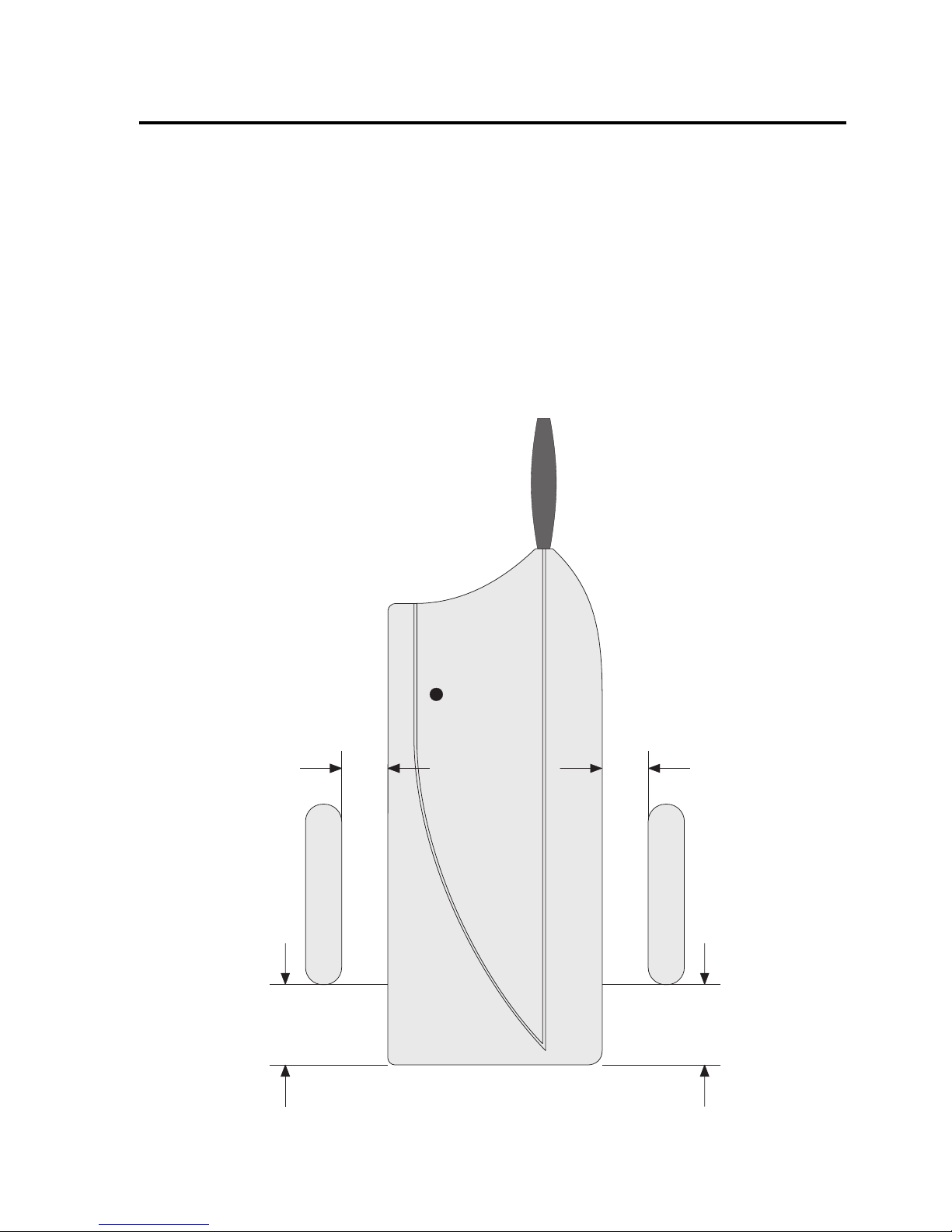
Figure 1
max. 25 mm max. 25 mm
20 mm
20 mm
Page 9

9
• Make absolutely sure that the lower edge of the magnet is 20mm away from
the lower edge of the door/window detector.
Mounting the magnet higher or lower reduces the magnetic range; the magnet
must be installed closer to the door/window detector!
The horizontal distance between the magnet and the door/window detector
should not exceed 25mm. The ideal distance is approx. 10-15mm.
Tip:
Before using screws to mount the device, you should first check
that it is working properly so as to avoid drilling any unattractive
holes in the ‘wrong’ location.
• The
internal magnet contact (the magnet sensor/reed switch in the door/
window detector) is normally switched off. It is activated when closed
for the first time via a magnet, and hereafter signals its state to the
alarm base station.
Due to this factory default setting, the door/window detector may
also be operated exclusively with external magnet sensors (without the supplied magnets).
A deactivation of the internal magnet contact (if activated) is only possible
by briefly removing the batteries (replacing the batteries) or by deleting and
re-registering the sensor.
• In addition to the internal magnet sensor you can attach several external
sensors to the door/window detector, such as when you have a wide window
bank with several windows/doors.
This refers only to NC contacts that must use the ‘KL2’ connection, see
page 12, figure 5.
When connecting several
external NC contacts, they
must be connected in series
(figure 2).
Do
not connect terminating
resistors!
Figure 2
NC-Kontakte
123
NC contacts
Page 10

10
• NO contacts on the door/window detector may also be used to complete
the monitoring, (use connection ‘KL1’, see page 12, figure 5).
They must have a potential-free/currentless switching output.
When connecting several NO contacts, they must be connected in
parallel (figure 3).
Do
not connect terminating resis-
tors here either!
Figure 3
Please note:
The ‘KL1’ connection for NO contacts is
always active, irrespective as to whether ‘disarmed’, ‘internally armed’ or ‘externally armed’
is set. This is ideal, if glass break sensors with NO contacts are
used. An alarm is set off immediately when a pane of glass is
smashed!
• The maximum attainable wiring length per alarm loop greatly depends on the
cable used and the transfer resistance of the magnet and/or glass break
sensors. Under ideal circumstances 100m or more is possible.
• When installing the door/window detector and magnet on metal doors or windows
the wireless range may be reduced.
• As a rule, the magnet is mounted on the moving part (window, door panel,
picture, for example) and the door/window detector ‘FAZ-TF’ is attached to
the static part (for example, window frame, door frame or wall). Please refer
to figure 1 on page 8 for the correct distance between magnet to door/window
detector.
• The magnet and the ‘FAZ-TF’ door/window detector may be attached with
commonly available double-sided tape.
You can use suitable screws to mount both components to the
surface and thus prevent them from being sabotaged. However,
you should first check that they are working properly so as to avoid
drilling any unattractive holes in the ‘wrong’ location.
NO-Kontakte
123
NO contacts
Page 11

11
b) Installing the door/window detector
• Open the casing; the two casing halves are secured by two catches (‘A’ in
figure 4 below).
Using a fingernail or a flat screwdriver carefully push the two catches approx.
1 millimetre inwards until the casing opens.
First press one catch inwards and pull the casing approx. 1-2 millimetres
apart at this location. Then press the other catch inwards; the casing now
opens.
• The hole ‘B’ is used for mounting the device with screws. The two openings
labelled ‘C’ are available to feed a cable into the door/window detector (for
hard-wired external sensors).
• Before installing the door/window detector ‘FAZ-TF’ in the desired location (see
following page), the cables of the external sensors (NC or NO contacts, if
available) must be inserted.
There are 2 openings (‘C’) on the back
side of the door/window detector,
through which the cables can be lead
inwards.
Later when installing the door/window
detector, make sure not to bend or pinch
the cables.
Figure 4
A
A
B
C
§
§
Page 12

12
In the door/window detector itself, the
cables are fed under the battery compartment for the LR44 button cells to
the screw terminal strips (otherwise the
LR44 button cells cannot be inserted
properly), see figure 5.
KL1:
The connection for external NO contacts is
always active, irrespective as
to whether ‘disarmed’, ‘internally armed’
or ‘externally armed’ is set; the alarm
base station sets off an alarm immediately upon a connection between the
two screw terminals!
KL2:
For external NC contacts (if using KL2,
the jumper in the terminal must be
re-
moved!)
• Attach the door/window detector using
the enclosed double-sided tape.
Alternatively you can attach it with a
screw through the opening ‘B’, see figure 4 on page 11. This also prevents it
from being easily removed from the wall
(sabotage protection).
The screw is also indicated in figure 5
to the right.
Figure 5
When drilling or fastening screws be careful not to accidentally damage any power supply lines, gas or water pipes as
this could pose a life-threatening danger!
•Do
not insert the batteries yet. The casing should initially remain open.
TA1
KL2KL1
D1
NO-Kontakt
NC-Kontakt
-
+
+
+
-
-
+
-
+
-
NC contacts
NO contacts
Page 13

13
• If you use the supplied magnet, attach it using the enclosed double-sided
tape (please note the recommended distances, see figure 1 on page 8).
Alternatively, you can use 2 screws to attach the magnet. Remove the
magnet’s casing using a flat screwdriver and screw in suitable screws.
Afterwards, replace the casing.
Page 14

14
8. Registering the door/window detector
‘FAZ 3000-TF-2’ with the base station
To register the sensors the alarm base station must first be set
to receive radio signals. Make sure that you also read the user
manual of the ‘FAZ 3000-Z’ alarm base station.
Carry out the following steps on the ‘FAZ 3000-Z’ alarm base station:
Description of procedure Display on LCD
• The alarm base station must be in the top level. The
LCD should appear as on the right, for example, with
the time and the date.
• Briefly press the ‘Menü a/A’ button on the control
unit of the ‘FAZ-Z’ alarm base station.
• Use the ‘y’ and ‘z’ buttons to select the ‘
sensorssensors
sensorssensors
sensors’
menu.
• Confirm your selection by briefly pressing the ‘OK’
button. ‘
sensors addsensors add
sensors addsensors add
sensors add’ appears on the LCD.
• Press the ‘OK’ button again.
The ‘
XX
XX
X’ character here stands for the number of
sensors that have already been registered
plus one.
Now the alarm base station is ready to receive the registration of
the ‘FAZ 3000-TF-2’ door/window detector.
• Go to the door/window detector that you wish to register with the alarm base
station.
sensors
disarm
16:30 14.12
troubles
sensors
add
sensor X
clear
Page 15

15
After installing of the door/window detector as described in section
7. b) on pages 11 to 13, the casing of the device is still open and
the batteries are not yet inserted.
• If you want to connect additional NC contacts to the ‘KL2’ connector, first
remove the jumper from the KL2 connector. When connecting several external
NC contacts, they must be connected in series. Do not connect terminating
resistors.
Please refer to figure 2 on page 9 for
connecting NC contacts.
• Insert 3 AAA batteries into the 3 battery
holders making sure polarity is correct. See
figure 6.
• The door/window detector contacts the
alarm base station by sending a radio signal.
The LED of the door/window detector
briefly lights up and the alarm base station
emits a short signal tone to confirm signal
reception.
• If the internal magnet contact is to be used
(with the supplied magnets), close the
window that the magnet is attached to.
This activates the internal magnet.
You may need to open and close the
windows again to ensure that a radio
signal is sent to the alarm base station.
Figure 6
TA1
KL2KL1
D1
+
-
+
-
+
-
+
-
Page 16

16
• If you have connected additional NO contacts to the ‘KL1’ connector (see
figure 3 on page 10), please insert 3 type ‘LR44’ button cells observing correct
polarity into the battery compartment, see figure 7.
The 3 button cells must be positioned such that each ‘plus’ (‘+’) points upwards
(please note the ‘+’ symbol on the circuit board in the battery compartment;
the lettering on the button cells).
Please note:
The ‘KL1’ connection for NO contacts is
always
active, irrespective as to whether ‘disarmed’,
‘internally armed’ or ‘externally armed’ is set.
This is ideal, if glass break sensors with NO
contacts are used. An alarm is set off immediately when a pane of glass is smashed!
If the glass break detector has a polarity specification, attach the ‘plus’ contact to the left KL1 screw terminal (see
figure 5).
• Close the door/window detector’s casing, so that the two locking hooks audibly click in.
Figure 7
TA1
KL2KL1
D1
+
-
+
-
+
-
+
-
+
+
+
-
Page 17

17
• Return to the alarm base station. The LCD’s display has changed. See the figure on the right. The
number ‘
33
33
3’ is the continuous sensor number (and
not ‘the third door/window detector’). The appropriate number is displayed, depending on the
number of sensors you already have registered
with the alarm base station.
• Use the buttons on the alarm base station to enter
the name of the sensor, for example, ‘
livingrlivingr
livingrlivingr
livingr
W1W1
W1W1
W1’ for ‘living room, window 1’.
f To enter the letters use the 2-9 buttons, each
of which represents several letters (click
through as with a mobile phone by repeatedly and quickly pressing the same button).
f Numbers and umlauts can also be found on
the buttons.
f Use the ‘0’ button to enter a space character.
f Special characters can be entered using the
‘y’ and ‘z’ buttons.
f You can use the ‘Menü a/A’ button to switch
between lower and upper case.
f The cursor automatically jumps to the next
position approx. one second after the last
button was pressed.
f You can use the ‘w C’ button to delete a
character you entered incorrectly by mistake.
• Once you have entered the name you require,
press the ‘OK’ button. The LCD has the display
shown on the right.
contact 3
_
contact 3
livingr W1
close : N
intern: N
Page 18

18
• Use the ‘x’ button to set the door/window detector
as an internal sensor (‘
intern: Yintern: Y
intern: Yintern: Y
intern: Y’) or an exter-
nal sensor (‘
intern:Nintern:N
intern:Nintern:N
intern:N’).
‘
intern: Nintern: N
intern: Nintern: N
intern: N’ External sensor; alarm set
off for ‘internally armed’
and ‘externally armed’
‘
intern: Yintern: Y
intern: Yintern: Y
intern: Y’ Internal sensor; alarm set
off only for ‘externally armed’
More information on this can be found in section
10 on page 21 (or in the user manual of the alarm
base station).
• By pressing the ‘y ’ button you can access the
closure group settings (the ‘
NN
NN
N’ in the upper line is
now underlined).
• Using the ‘x’ button you can select whether the
door/window detector belongs to the closure group
(‘
YY
YY
Y’), or not (‘
NN
NN
N’).
You can find further information on this in section
10, page 21 (or in the alarm base station’s user
manual).
• By pressing the ‘OK’ button, you access the
registration function for the next sensor.
The ‘
XX
XX
X’ on the right in the figure stands for the
number of the next free sensor memory location.
Now another door/window detector (or a PIR
motion detector or smoke detector) can be registered.
• Press the ‘wC’ button three times to exit the alarm
base station’s registration mode. You are in the
normal display mode again (top level) of the alarm
base station.
close : N
intern: Y
close : N
intern: Y
sensor X
clear
disarm
16:45 14.12
Page 19

19
9. Opening the door/window detector’s
casing, replacing the batteries
Before the casing of the door/window detector may be opened,
the alarm base station must be set to maintenance mode. Otherwise the alarm base station immediately sets off the sabotage
alarm when the casing is opened.
Proceed as follows:
• The alarm base station must be in the top level.
The LCD should appear as on the right, for example, with the time and the date.
• Briefly press the ‘Menü a/A’ button on the control
unit of the ‘FAZ-Z’ alarm base station.
• Use the ‘y’ and ‘z’ buttons to select the
‘
serviceservice
serviceservice
service’ menu. See the figure on the right.
• Confirm your selection by briefly pressing the ‘OK’
button.
The first sensor that was registered with the alarm
base station is displayed.
• Use the ‘y’ and ‘z’ buttons to select the sensor
that you wish to open (to replace the batteries or
to change the wiring, for instance).
Other devices may be selected with the ‘x’ button (siren control, activation switch, alarm dialler,
PC interface and/or alarm base station).
• Confirm your selection by briefly pressing the ‘OK’
button.
You can now open the casing of the selected
sensor without setting off a sabotage alarm, in order
to replace the batteries, for example. No data is
lost and the sensor or the device does not need
to be registered again afterwards.
service
troubles
disarm
17:25 20.03
contact 1
livingr W1
contact 4
- service -
contact 4
bedr W1
Page 20

20
Once the new batteries have been inserted the
sensor’s LED briefly blinks once. The radio connection to the alarm base station has been established and checked.
For instance, instead of replacing batteries, the
wiring of the door/window detector can be changed,
to connect additional external sensors, for example.
• Once you have finished replacing the batteries
or made changes to the wiring, close the sensor’s
casing again.
• Briefly press the ‘OK’ button on the alarm base
station to end the maintenance. You are now in
the sensor list again. You can use the ‘y’ and ‘z’
buttons to select another sensor (or select a device
using the ‘x’ button).
• You can exit the ‘service’ mode by pressing the
‘wC’ button three times. This returns you to the
normal display mode (top level) of the alarm base
station.
Please note:
If the internal magnet contact of the door/window detector is used
(with the supplied magnets, either mounted on the left or the right),
the contact must be triggered one time after battery replacement in order to reactivate the internal magnet contact.
After replacing the batteries, open and close the window or
door to which the magnet is attached 1 time.
disarm
17:47 20.03
contact 4
bedr W1
Page 21

21
10. Explanation of ‘Internal/external
sensor’ and ‘closure group’
a) Internal/external sensor
By assigning a sensor as an internal or an external sensor, you
can determine how each sensor responds:
Intern: NIntern: N
Intern: NIntern: N
Intern: N External sensor; alarm is set off for
‘internally armed’ and
‘externally armed’
Intern: YIntern: Y
Intern: YIntern: Y
Intern: Y Internal sensor; alarm is only set off for
‘externally armed’
The alarm base station has two activation options:
1. ‘Internally armed’
The ‘internally armed’ function provides protection to the exterior of a building,
such as, when you are in your house at night, for instance.
Only sensors that are involved in protecting the exterior of the building are
allowed to respond. These include door/window detectors in an apartment
or PIR motion detectors that are mounted
externally.
PIR motion detectors located
inside the apartment are not allowed to respond
and must therefore be set to ‘
Intern: YIntern: Y
Intern: YIntern: Y
Intern: Y’.
2. ‘Externally armed’
The ‘externally armed’ function is used to monitor an unoccupied building
such as a house, when no one is at home, for instance.
The exterior shell of the building is monitored (using door/window detectors,
for example) as well as the indoor areas (provided that internal PIR motion
detectors are installed).
All the sensors set off the alarm, irrespective of how they are assigned.
Page 22

22
b) Closure group
All sensors that directly protect external doors such as door/window detectors and PIR motion detectors that are mounted outside
should be assigned to the so-called ‘closure group’.
When the alarm system is activated and in the case of an alarm the sensors
in the ‘closure group’ initially only set off the internal siren of the ‘FAZ 3000Z’ alarm base station (the default setting for the alarm duration is 30 seconds,
which you can adjust).
Only afterwards is the ‘normal’ alarm set off (for example, externally via a
siren and a strobe light).
Advantage:
If you forget to deactivate the alarm system when you enter your
house, initially only the internal siren is set off.
You then have 30 seconds in which you can deactivate the alarm
system, before the external siren (and the alarm dialler or PC
interface, for example) signal the alarm outside the building.
Disadvantage:
When there is a ‘real’ break-in, this also forewarns the intruder.
The intruder could then attempt to destroy the alarm system or
parts of the alarm system, if these devices are easily accessible
and are not protected against force.
To avoid this problem it makes sense to use the ‘FAZ 3000-SE’ radio
activation switch with a bolt switching contact.
This device deactivates the alarm system when the house door is opened
properly, and consequently prevents false alarms. At the same time the alarm
is set off without a delay, if one of the sensors activates.
Page 23

23
11. Maintenance and cleaning
The product requires no servicing except for battery replacement. Any repairs
should be carried out by a skilled technician or a professional workshop.
Clean the product with a soft, clean, dry and lint-free cloth. To remove heavier
dirt, use a cloth which is slightly moistened with lukewarm water.
Do not use any solvent-based cleaning agents as these may damage the plastic
casing.
12. Disposal
a) General information
When the product is no longer usable, dispose of it in accordance
with the applicable statutory regulations.
b) Batteries and rechargeable batteries
As the consumer, you are legally obliged to return all your used batteries and
rechargeable batteries. Do not dispose of your used batteries via the
household rubbish!
Batteries/rechargeable batteries containing harmful substances
are marked with the following icons, which alert you to the fact
that disposal via the household rubbish is prohibited. The identifiers for the respective heavy metals are: Cd=cadmium,
Hg=mercury, Pb=lead (identifier is on the battery/rechargeable
battery, for example, under the rubbish bin icons on the left).
You can return your used batteries/rechargeable batteries free of
charge to any authorised disposal station in your area, in our stores
or in any other store where batteries/rechargeable batteries are
sold.
By doing so you comply with your legal obligations and also make a contribution
to environmental protection.
Page 24

24
13. Information on the range
Ranges and interference
• The door/window detector operates in the 868MHz range, which is also used
by other radio services. Therefore devices that operate on the same or
neighbouring frequencies may restrict both its operation and its range.
• The specified range of 300m is the free-field range, which means the range
with visual contact between the transmitter and receiver. In practice, however, ceilings, walls, garages or neighbouring buildings between the transmitter and the receiver may affect and reduce the range accordingly.
• The range also depends on the version of the available alarm base station.
Earlier versions of the alarm base station had a range of up to 100m; for
others, an external antenna (‘FAZ-HF’) permitted larger ranges.
• The actual attainable distance between the transmitter and the receiver in
normal operation greatly depends on the installation location and the surroundings.
As a rule – when mounted in a family home, for example – all the components
should work properly and there should be no radio reception problems.
Other causes of reduced ranges:
• All types of high-frequency interference
• Any buildings or vegetation
• Conductive metal parts that are located near the devices or within or near
their transmission path, for example, radiators, metallised insulation glass
windows, reinforced concrete ceilings and so on.
• Influence on the radiation pattern of antennas due to the distance from the
transmitter or receiver to conductive surfaces or objects (also to human
bodies or the ground)
• Broadband interference in urban areas that reduces the signal-to-noise ratio;
the signal is no longer recognised due to this ‘noise’
• Interference radiation resulting from insufficiently shielded electronic devices,
for example, operating computers or similar
Page 25

25
14. Technical specifications
• Option to connect additional external NC and NO contacts
• Installation with supplied magnets possible on left or right
• Batteries: .................................... 3 x AAA batteries
(additionally 3 x button cells LR44, when NO contacts are connected, for
example for NO model glass break sensors)
• Dimensions: ............................... 53mm x 163mm x 24mm (W x H x D)
• Frequency: ................................. 868.35MHz
• Range: ........................................ up to 300m in free-field (*)
(*) The range depends on the version of the ‘FAZ 3000-Z’ alarm base station
that is used. Earlier versions only permitted a range of up to 100m. Please
also see section 13.
Page 26

26
15. Brief instructions
a) Registering the door/window detector with the
alarm base station
• Install the door/window detector, but do not insert batteries yet
• Set the alarm base station to the sensor search mode
• Insert batteries into the door/window detector
• The alarm base station should now recognise the door/window detector
• Enter a name for the door/window detector
• Set properties for the door/window detector (closure group and internal/external
sensors)
• Return to the top level of the alarm base station (press the ‘wC’ three times)
• If the internal magnet sensor is to be used (in connection with the supplied
magnets), open and close the window 1 time, in order to activate the magnet
sensor
b) Further connection of external NC/NO contacts
• Set the door/window detector on the alarm base station to the maintenance
mode
• Open the door/window detector’s casing
• Lay or change wiring
• If NO contacts are to be attached to the ‘KL1’ terminal, 3 additional type
LR44 button cells must be inserted
• If NC contacts are to be connected to the ‘KL2’ terminal, the jumper (factory
installed) on the ‘KL2’ terminal must first be removed.
• Close the casing
• Exit the maintenance mode of the alarm base station
• If the internal magnet sensor is to be used (in connection with the supplied
magnets), open and close the window 1 time, in order to activate the magnet
sensor again
The door/window detector may also be operated exclusively with
external NC/NO contacts, the internal magnet contact is always
automatically deactivated after batteries have been replaced.
Page 27

27
c) Opening the casing, replacing the batteries
• Set the door/window detector on the alarm base station to the maintenance
mode
• Open the door/window detector’s casing
• Replacing the batteries
• Close the casing
• Exit the maintenance mode
• If the internal magnet sensor is to be used (in connection with the supplied
magnets), open and close the window 1 time, in order to activate the internal
magnet sensor
16. Declaration of conformity (DOC)
We, Conrad Electronic, Klaus-Conrad-Straße 1, 92240 Hirschau (Germany),
hereby declare that this product complies with the fundamental requirements
and other relevant regulations of directive 1999/5/EC.
You can find the declaration of conformity for this product at
www.conrad.com
 Loading...