

Page 1

Car Alarm System „GKA100“
Item No. 841086
Version 02/14
OPERATING INSTRUCTIONS
Page 2

2
Table of Contents
Page
1. Introduction ...................................................................................................................... 4
2. Intended Use.................................................................................................................... 5
3. Scope of Delivery ............................................................................................................ 5
4. Explanation of Symbols ...................................................................................................6
5. Safety Information ............................................................................................................ 6
6. General Notes on Rechargeable Batteries .................................................................... 8
7. Product Description .........................................................................................................9
8. Connections and LEDs..................................................................................................10
8.1 Casing Overview ................................................................................................. 11
8.2 Description of the Connections .......................................................................... 13
8.3 Notes on the Installation ..................................................................................... 17
8.4 Notes on the Electrical Connection .................................................................... 19
9. Commissioning - First Steps ......................................................................................... 20
9.1 Operating Voltage ............................................................................................... 20
9.2 Changing the PIN Code to „1513“ ......................................................................20
9.3 SIM Card Insertion .............................................................................................. 21
10. General Descriptions ..................................................................................................... 22
10.1 Product Status and Mode ................................................................................... 22
10.2 Wireless Remote Control ....................................................................................24
10.2.1 Product Control with the Wireless Remote Control .............................24
10.2.2 Wireless Remote Control Battery Change ...........................................25
10.2.3 Coupling of a Remote Control to the Device ........................................25
11. Configuration via Text Message ....................................................................................26
11.1 Introduction to the Command Format ................................................................ 26
11.2 Special Commands ............................................................................................. 29
12. Functional Descriptions ................................................................................................. 30
12.1 General Configuration Commands .................................................................... 30
12.1.1 Setting Time and Date (TIME, DATE) ...................................................30
12.1.2 Administration of Phone Book (TEL, TEL1,…) ..................................... 31
12.1.3 Changing the Device Name (Name) ..................................................... 33
Page 3

3
Page
12.1.4 Changing the PIN Code (PIN) ............................................................... 34
12.1.5 Changing the Calling Sound and Volume Settings (AUDIO)............... 34
12.2 In- and Outputs ................................................................................................... 36
12.2.1 Relay Outputs (OUT1, OUT2) ............................................................... 36
12.2.2 Switching Inputs (IN1, IN2).................................................................... 38
12.2.3 Operating Voltage Monitoring (VOLTAGE) ........................................... 40
12.2.4 Vibration Alarm (SHOCK) ...................................................................... 41
12.3 Additional Functions ...........................................................................................42
12.3.1 Time Limitation Alarm (HOLDALARM) ................................................. 42
12.3.2 Wireless Remote Control and its Function (RFBUTTON) ...................44
12.3.3 Reaction at Call (INCALL) .....................................................................46
12.4 Position Determination........................................................................................ 48
12.4.1 GSM Cell Location (CELL) ....................................................................48
12.4.2 General GPS Localisation (GPS) ......................................................... 49
12.4.3 Submission of a Web Link with GPS Position (GPSMAP) .................. 50
12.4.4 Automatic Submission (GPS, GPSMAP, Special Function) ................ 51
12.4.5 Energy Savings Mode (GPSSAVE) ...................................................... 52
12.4.6 Programming the „GPSZONE“ ..............................................................53
12.5 System Functions................................................................................................ 56
12.5.1 Time between Two Alarm Messages (IDLEALARM)............................ 56
12.5.2 Voltage Hysteresis (HYSVOLT) ............................................................58
12.5.3 Resetting to Basic Setting (RESET SETUP) ........................................59
13. Restoring Default Settings ............................................................................................ 59
14. Disposal ......................................................................................................................... 60
14.1 Product ................................................................................................................ 60
14.2 Batteries and Rechargeable Batteries ...............................................................60
15. Maintenance ..................................................................................................................60
16. Declaration of Conformity (DOC) .................................................................................. 61
17. Fuse Replacement ........................................................................................................ 61
18. Technical Data ............................................................................................................... 62
Page 4

4
1. Introduction
Dear Customer,
Thank you for purchasing this product.
This product complies with the statutory national and European requirements. To maintain this
status and to ensure safe operation, you as the user must observe these operating instructions!
Read the complete operating instructions before taking the product into
operation; observe all operating notes and safety information.
All company names and product names are trademarks of their respective owners. All rights
reserved.
If there are any technical questions, contact:
Germany: Tel. no.: +49 9604 / 40 88 80
Fax. no.: +49 9604 / 40 88 48
E-mail: tkb@conrad.de
Mon. to Thur. 8.00am to 4.30pm, Fri. 8.00am to 2.00pm
Please note:
These operating instructions describe the function and operation at the time of print
(see date on the top right of the title page).
Changes that serve product improvement can be performed at any time. The most
current operating instructions are offered on our websites in the download area for
the respective product on our websites in a timely manner.
Page 5

5
2. Intended Use
The product serves to monitor an object. For this, sensors like vibration, switching inputs (up
to 32 V/DC) and the GPS signal are available. The product must only be installed in the driver
space, splash-water protection is required.
Two switching relays for 30 V/DC, 2 A can be switched remote-controlledly by consumers or
automatically. Switching the consumer must not influence the safety and operational readiness
of the vehicle.
An external microphone and a speaker permit phone calls. Interior monitoring must be
according to the statutory provisions.
Any other use than described before is not intended and may cause loss of warranty/
guarantee.
The customer is responsible for application of the product in accordance with the law. Conrad
Electronic does not assume any responsibility/liability exceeding application of the product as
described here.
No part of this product must be modified or converted.
Read these operating instructions thoroughly and carefully, they contain a lot of important
information for assembly, commissioning and operation. Observe all safety information in
these operating instructions!
3. Scope of Delivery
• Car alarm system
• Remote Control
• Microphone
• Speakers
• Light diode
• Mains cable
• Various connection wires
• Operating instructions
Page 6

6
4. Explanation of Symbols
An exclamation mark in a triangle indicates important notes in these operating
instructions that must be strictly observed.
The „hand“ symbol indicates special information and advice on operation.
5. Safety Information
The guarantee/warranty will expire if damage is incurred resulting from noncompliance with the operating instructions! We do not assume any liability
for consequential damage!
We do not assume any liability for damage to property or personal injury
caused by improper use or the failure to observe the safety instructions! In
such cases the guarantee/warranty will expire!
• For safety and licensing reasons (CE), unauthorised conversion and/or
modification of the system is not permitted.
• The system only serves to trigger alarms but does not relieve the user from his
diligence obligation.
• Setting when the relay switches and what effects this has is subject to the area
of responsibility of the customer. The manufacturer does not assume any liability
for damage that occurs in this case.
• The GPS functions only serve to monitor property. The customer is personally
responsible for compliance with the statutory requirements for further monitoring.
• During installation and operation, observe the applicable approval provisions
and the road traffic ordinance (Straßenverkehrsordnung).
• Ensure proper commissioning of the system. Observe the operating instructions
for it.
• Avoid strong mechanical strain on the system components.
• Do not expose the device to any high temperatures, dripping or splashing water,
strong vibrations or heavy mechanical stress.
• Consult an expert when in doubt as to the operation, the safety or the connection
of the system.
Page 7

7
• Do not leave the packaging material lying around carelessly since such materials
can become dangerous toys in the hands of children.
• Keep the device out of reach of children. It is not a toy.
• Also observe the additional safety information in the individual chapters of these
instructions.
• If you are not sure about the correct connection or if questions arise which are not
covered by the operating instructions, please do not hesitate to contact us or
another specialist.
Page 8

8
6. General Notes on Rechargeable Batteries
• Keep the rechargeable battery out of reach of children.
• Leaking or damaged batteries/rechargeable batteries can cause chemical burns to skin
when touched without the use of adequate protective gloves.
• The rechargeable battery must never be short-circuited or thrown into fire. There is a risk of
fire and explosion!
• Never open or disassemble the rechargeable battery!
• If the rechargeable battery heats up strongly when charging, interrupt the charging process!
• Never charge the battery unobserved.
• For reasons of safety, only charge the rechargeable battery on a heat-resistant surface.
• If the rechargeable battery shows any deformation, holes or other obvious defects, no longer
use the rechargeable battery and do not try to charge it.
• Dispose of the rechargeable battery environmentally compatibly.
Page 9

9
7. Product Description
The car alarm system can be used to monitor a vehicle. The primary task is not in frightening
the thief away via the speaker but via live transmission of an alarm message to up to 6 phone
numbers by text message.
If the sensors and external electronics (connected to the switching inputs) recognise any
impermissible interaction, various actions like alarm via text message or switching consumers
may be triggered.
The customer may at any time perform other actions by sending text message from his mobile
phone, e.g. determine the current GPS position (coordination or web link), request the status,
switch the relay, check the switching inputs or perform a „silent call“ to hear what is currently
taking place inside the vehicle.
The microphone or speaker can be used to accept calls and call pre-set phone numbers.
Many transverse functions (switching relays when deactivating the alarm, the call causes an
answering text message with the current GPS position, etc) can be used by the customer to
configure the product as desired.
The GPS receiver is used to determine and monitor GPS zones (Area, GeoFence), i.e. places
where the product may be present.
The USB-interface, which is not mandatory for operation or configuration can be used by the
customer for firmware updates to receive further functions.
The product is secured against manipulation with an internal battery.
Page 10
10
8. Connections and LEDs
The product is explained step by step in the following chapters.
To ensure that the device is set up correctly, make sure to read these operating
instructions, including the safety instructions, completely and attentively before
use.
Assembly and electrical connection of the system must be performed by a specialist.
Page 11

11
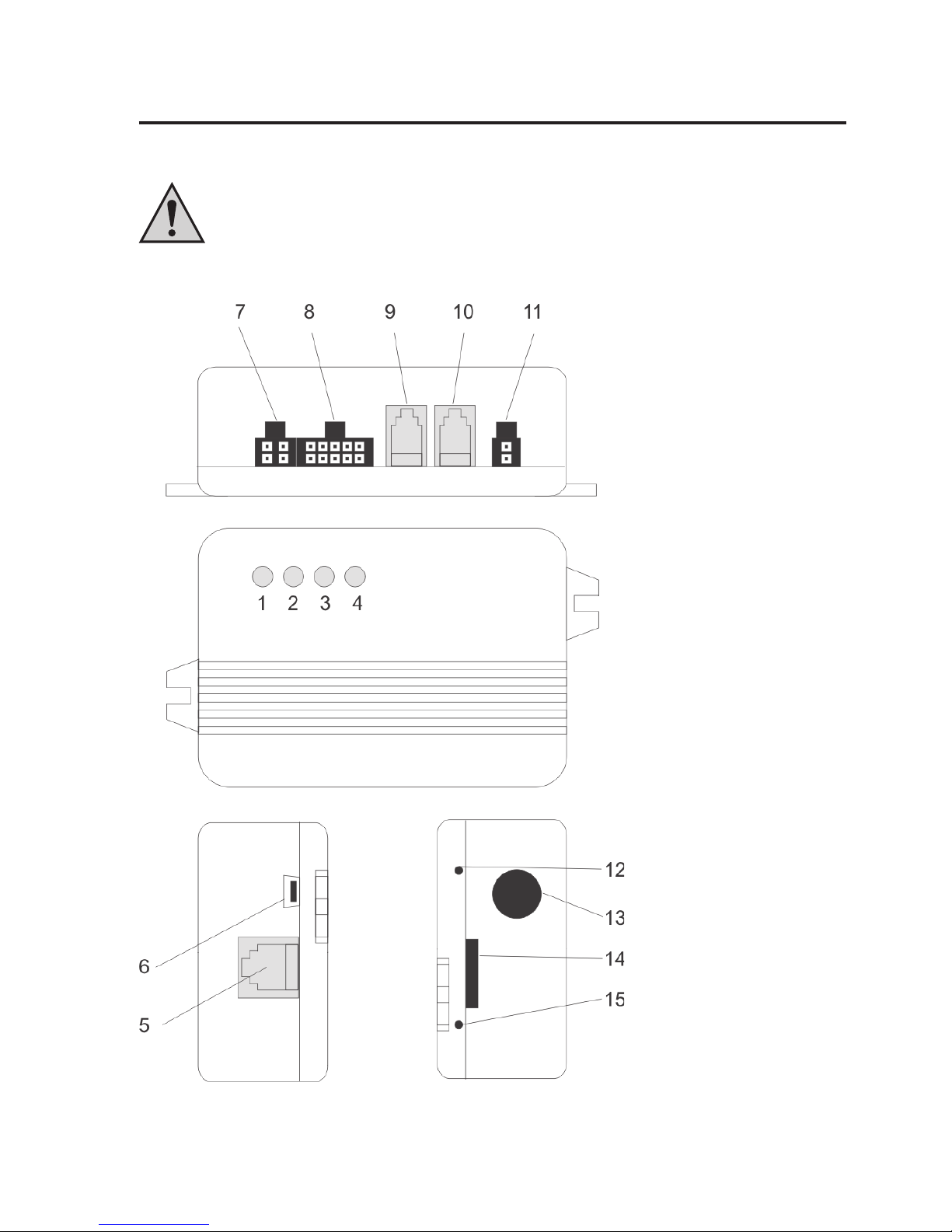
8.1 Casing Overview
1. GSM status LED
2. Battery status LED
3. GPS status LED
4. RF status LED (remote control)
5. Expansion port
6. Mini-USB
7. External alarm LED and switching plus input
8. Switching inputs and relay connections
9. Microphone/ speaker connection
10. Microphone/ speaker connection
11. External power supply
12. Programming switch (RF)
13. Opening GPS cable
14. SIM card holder
15. RESET
Page 12
12
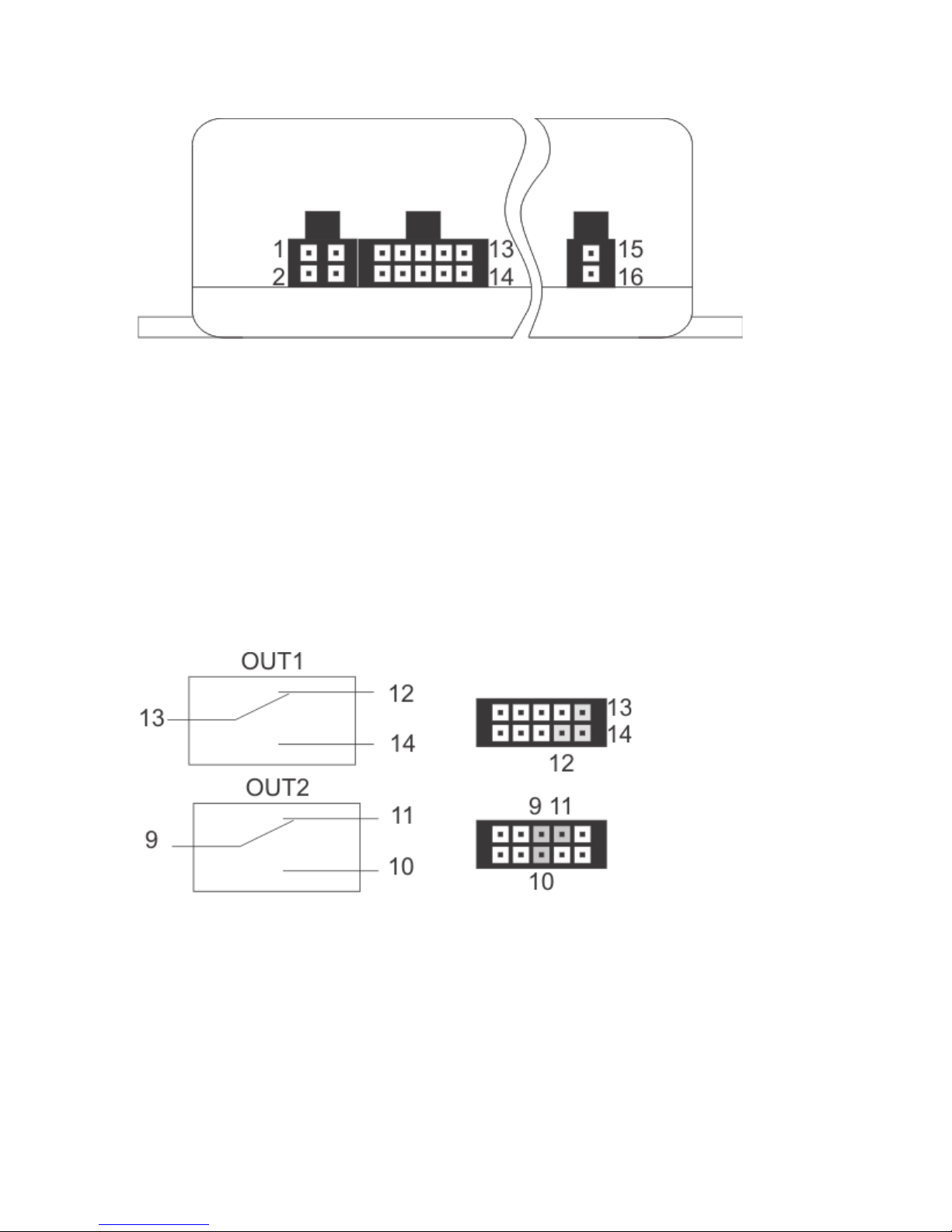
In the following, the PIN assignments are described.
9. OUT2 relay output common
10. OUT2 relay output closer
11. OUT2 relay output opener
12. OUT1 relay output opener
13. OUT1 relay output common
14. OUT1 relay output closer
15. VCC voltage supply plus/+
16. GND voltage supply minus/-
1. LED + external alarm LED
2. LED – external alarm LED
3. P+ switching plus
4. Not assigned
5. IN1 switching input a
6. IN1 switching input b
7. IN2 switching input a
8. IN2 switching input b
All relays are in the condition „OFF/RESET“.
The PIN assignment of the product is printed on the reverse of the device.
However, observe that the PIN assignment printed on for the connection “OUT2” is,
unfortunately, incorrect in the first series. The above assignment is correct.
Page 13

13
8.2 Description of the Connections
GSM status LED (1):
This LED shows the current GSM status. For this, the LED has the following presentation
options:
• LED is lit green: Searching for GSM network
• LED flashes green (every 1 s): Device registered in the network
• LED flashes green (every 1/2 s): Call / phone connection
• LED flashes red: No network connection / PIN error / invalid SIM card / PUK / …
• LED off: No power supply present / device defective if voltage supply and SIM card are
present
Battery status LED (2):
The internal battery is charged and managed via a separate hardware. Thus, the battery can
also be charged when no SIM card is inserted and the entire GSM hardware is deactivated.
It is unimportant of whether the battery is charged via the external voltage supply (on-board
voltage) or via USB.
This LED provides the following information:
• LED is lit red: The battery is being charged
• LED is lit green: The battery is charged
• LED is lit red and green: An error was recognised (e.g. no battery present)
• LED off: No external voltage supply present
GPS status LED (3):
This LED is used to recognise the activity and status of the external GPS receiver.
The following display options are available for this:
• LED flashes blue: Current GPS position determined
• LED is lit blue: GPS position not determined / determinable
• LED off: GPS module is in sleeper mode / switched off / not present
Page 14

14
RF status LED (4):
This LED shows whether the RF recipient of the wireless remote control has received a signal
from a valid remote control.
Observe that only correctly coupled remote controls are recognised and displayed. How to
couple a remote control can be taken from the corresponding chapter.
The LED has the following display information accordingly:
• LED flashes red: Signal received by valid remote control
• LED off: Waiting for signal
RF button:
You can reach the RF button with a pointed object through the corresponding opening. This
is required to couple a new / different wireless remote control with the product. For more on
this, see the corresponding chapter.
Reset button:
The device can be reset to factory settings with a pointed object. For more on this, see the
corresponding chapter.
Feedthrough GPS receiver:
The GPS receiver is delivered pre-assembled. The GPS receiver must be placed so that a sight
connection to the sky is present with as few obstacles as possible. Particularly observe panes
that are applied with film or vaporised because they interfere with or even block the GPS signal.
The same applies for front or rear window heatings.
External power supply:
Use pins 15 and 16 to supply the device with the vehicle’s battery voltage (permanent plus).
The voltage range is between 6 and 32 V/DC and thus matches nearly any important vehicle
voltage.
The current load may be up to 700 mA (peak) at bad GSM reception, active switching relays
and active GPS.
Page 15

15
Two connections for speaker / microphone:
Either the included microphone or the speaker can be connected to the two RJ12 sockets. Both
sockets are assigned in precisely the same manner and switched in parallel.
The PIN assignment corresponds to that of a standard phone handset. Function
cannot be guaranteed for every phone handset.
External LED connection:
Pins 1 and 2 are intended for connection of the external LED. Please use recommended
accessories only (see www.conrad.com)
P+ switching plus recognition:
Connect a switching plus signal to pin 3 and 4. Functionally, however, this input only serves
to directly trigger an alarm because the switching plus refers to an impermissible action in the
„ALARM ENABLE“ mode.
The reference potential is GND from the external power supply (16). No voltage above 32 V
must be present here.
To avoid unintended short circuit for wiring, only the „P+“ pin (3) is assigned. The
other pin was not connected. Therefore, if no reaction appears when the switching
plus is activated, this pin may have been connected.
Switching inputs IN1 / IN2:
The pins 5 and 6 for „IN1“, as well as 7 and 8 for „IN2“ serve to recognise various switching
conditions in the vehicle. These lines can be directly connected, e.g. to lamps, door contacts
or other switchable consumers. An integrated rectifier and optocoupler protects the device
from polarity reversal and short circuit.
It must only be ensured that a voltage difference of at least 4 V and no more than 32 V is pending
between the two pins (no matter the polarity) and the respective switching input is recognised
as „HIGH“. A voltage of less than 2.5 V is securely interpreted as „LOW“. The area between
serves to prevent multiple alarming and can only be assigned to a level under specific
circumstances. For more on this, see the corresponding chapter.
Page 16

16
Relay switching outputs OUT1 / OUT2:
The device has two relays with alternate contract that are intended for a voltage of 30 V and
a current of 2 A.
When a higher power is to be switched, the corresponding relays must be
connected externally.
The relays are not bistable and accordingly return to „OFF“ or „RESET“ when all voltage
supplies (battery, USB, external voltage) drop or a system reset is performed.
Observe that the device for the relays has no extra fuse installed. Therefore,
provide an external fuse if required (depending on application case).
Improper wiring and switching of impermissible consumers (buzzer, ignition plus)
may cause a risk of short circuit, fire and loss of the general operating permit.
Expansion port:
This port was intended for possible expansions. This is possibly available on our website
www.conrad.com as accessory for order number 841086).
USB connection:
You may use this USB connection to update the product firmware to the latest version. For this,
the corresponding update programmes may be provided on the product side at www.conrad.com.
The software version currently installed on the product can be taken from every answer text
message.
Page 17

17
8.3 Notes on the Installation
• It can be installed in any position.
• Observe that there is enough space for cables when choosing the installation position.
Strongly bent cables (particularly right behind the plug) increase the risk of cable breaks and
may cause contact problems in the plug. The PCB is under a strong mechanical strain due
to this.
• To warrant the device function, choose a mounting site where the GMS network reception
is as good as possible.
• The application site should be protected against overheating of the device, excessive
moisture and dust.
• The product should be taken to a site where vehicle vibration can be measured.
• The product must not be subject to continuous strong vibrations (vibrating machines, direct
motor/chassis contact, etc.).
• The product is not protected against weather and therefore must be installed inside the
vehicle.
• Observe that the SIM card holder position was placed close to the casing holder on purpose.
You may use a corresponding screw to secure the SIM card against impermissible removal.
Replacing the battery:
If the battery must be replaced, observe the following instructions:
1. All removal cable connections must be removed from the device; separate it from the
power supply under all circumstances
2. Remove the SIM card.
3. Loosen the 4 screws on the product bottom; turn it out.
4. Now the casing may be used carefully; do not apply any force!
Observe the GPS receiver! It may be necessary to loosen the screws at the GPS
cables for relief.
5. The battery is connected to the main PCB via a plug secured against polarity reversal;
carefully disconnect the battery.
Page 18

18
Any changes in the vehicle that become necessary for the installation of the alarm
system or other components must be carried out in such a way that neither traffic
security nor the constructional and functional stability of the car are affected.
The operation permit may lapse even when sawing out the sheet part.
No parts must be installed in the airbag trigger area because this may cause injury
to the vehicle passengers in case of accident.
Never loosen the plugs for an airbag, which may cause unintended triggering of the
airbag or functional impairment.
If there are any doubts regarding selection of the installation site, inquire for
information from your car vendor.
Before drilling the bores, make sure that no electric cables, brake lines, the fuel tank
or similar are damaged.
When using tools to install your alarm system, observe the tool manufacturer’s
safety information.
When installing the product, take into consideration the risk of accident which can
arise from devices being torn away in the case of an accident. Therefore, you should
secure every component in a place where it cannot be dangerous to passengers.
In doubt, installation must be performed by a specialist.
Page 19

19
8.4 Notes on the Electrical Connection
• The maximum load resilience in the relays must not be exceeded. If required, they must be
protected from overload with additional external fuses.
• The external cables must be kept as short as possible and remaining line lengths must not
be coiled.
• Too-strong temperature fluctuations may lead to temporary impairment and require manual
reset in extreme cases.
• The product is not intended for the „Safety“ area and therefore does not correspond to any
SIL/ASIL level.
The electrical connection must be made by a specialist.
To avoid short circuits and resulting damage to the device, the negative pole (GND/
earth) must be disconnected during connection.
Only connect the negative pole of the vehicle battery when you have completely
connected the device and checked the connections.
Observe the notes of the vehicle manufacturer so that the stored data of the vehicle
are not lost (e.g. radio code).
You should only use a voltmeter or a diode test lamp for checking the voltage on
the on-board cables as normal test lamps consume excessive currents and can
thus damage the electronic system of the car.
When laying the cables, make sure that they are not squeezed or scoured on sharp
edges. Use rubber grommets for the feed-though points.
When placing the sensor lines in the trunk, use rubber sleeves or something similar
to avoid impairing tightness of the vehicle interior.
When placing the lines in door pillars, etc., ensure that you do not impair any safetyrelevant devices (e.g. side airbags). The lines must not be placed in the airbag
trigger area.
Page 20

20
9. Commissioning - First Steps
Prior to commissioning the product, check whether it is suited for the intended application!
In case of doubt, always contact a specialist, expert or the manufacturer of the products used!
The following is needed for operation and configuration of the device:
• A common mobile phone with SIM card for configuration of the device.
• An additional SIM card (prepaid or contract) for the device.
• A voltage source (USB port or direct voltage source)
9.1 Operating Voltage
The product may be supplied with power via USB as well for testing. The battery LED shows
whether the operating voltage was connected correctly, no matter the device status:
• LED off = no external voltage supply
• LED green/red = external voltage supply present
9.2 Changing the PIN Code to „1513“
Every SIM card has a PIN code. Because the car alarm system uses its own PIN processing,
the SIM card PIN code must be changed to that of the product.
The following steps are required for this:
1. The SIM card intended for the car alarm system must be inserted in a mobile phone.
2. According to the operating instructions of the mobile phone, the PIN code must be
changed to 1513.
3. The SIM card with the changed PIN code must be removed from the mobile phone.
4. The SIM card with the changed PIN code can now be inserted in the intended device slot.
The SIM card slot for this is on the short device side.
Page 21

21
9.3 SIM Card Insertion
The SIM card with the PIN number „1513“ must be
inserted in the device as shown in the figure on the
right.
After insertion of the SIM card, the device switches on
automatically; this is signalled by the green flashing
GSM status LED (1).
First, the LED1 remains lit green (network search);
after a few seconds, the LED1 should start flashing
(network found, device ready for operation).
If the green LED does not start to flash, there is no
connection to the GSM network. In this case, the
network quality and function of the SIM card must be
inspected at the product site with a separate mobile
phone.
If the LED1 flashes red, there is an error when connecting to the GSM provider or the PIN
number is incorrect. In this case, the device must be reset to factory settings. Furthermore, the
SIM card (PIN/PUK/activation) must be inspected and the receiver quality at the device
position must be verified with a separate mobile phone.
If the device used to be used with another SIM card, there is the option of the PIN
number in the product being changed and no longer matching the PIN number of
the SIM card. In this case, reset the device to factory settings (section „Factory
Reset“) and manually set the SIM card PIN in your mobile phone to PIN „1513“.
The SIM card may have been locked in the meantime and must be unlocked with
the PUK.
Page 22

22
10. General Descriptions
This product is not a common alarm system. The GSM/GPS function increase the functional
scope and thus also complexity. In the following, the most important items that you should
know and observe when using the product are noted.
• These instructions assume the functional scope at the time of initial delivery. The option of
the firmware update may add new functions via the USB interface.
• All text message answer examples are to be understood symbolically. Actual implementation
may vary. The examples should only show the information to be expected, their format and
writing.
10.1 Product Status and Mode
The alarm system functions of the product have only two operating modes:
„ALARM ENABLE“ (alarm activated)
To get to this mode, use the right button on the remote control, the text message command
„ALARM ENABLE“ and, depending on configuration, e.g. a call.
Whether or not the alarm is active can be seen by the external ALARM LED at the latest. If it
neither flashes nor is lit, the product cannot be in the alarm state.
Only in this mode can the product send text messages independently and without any
customer interaction, and perform a recall depending on configuration.
This only takes place when an activated alarm source recognises an alarm incident (vibration,
too-low external voltage, switching inputs, etc.). Only in this case, all phone numbers in the
device phonebook (not that of the SIM card) will receive the corresponding alarm text
message.
The phone number for a recall must be configured separately in the corresponding command.
Transfer to this mode is signalled with the following sound signal using the external speaker:
1/4 s sound low —> 1/4 s sound high
Page 23

23
„ALARM DISABLE“ (alarm deactivated)
In this mode, GSM costs may only arise when customer interaction triggers it. The product only
sends text messages if a text message with the correct PIN or a call from a phone number in
the phone book has been received, depending on configuration.
The device will only call on direct command anymore (text message, button, call, etc.) from the
customer. The product then also cannot trigger an alarm.
Transfer to this mode is signalled with the following sound signal using the external speaker:
1/4 s sound high —> 1/4 s sound low
Switching plus (P+)
If the switching plus should be activated (12 V) while the alarm is active, this is recognised as
an alarm situation and an alarm is triggered. Deactivation of the switching plus in case of alarm
has no effect.
When the switching plus is active, no alarm sound can be output via the speaker. This has been
chosen for safety reasons to prevent the driver from being annoyed or surprised by the sudden
alarm, which may cause an accident.
Call (incoming)
A call from an unknown phone number will be rejected at once when the alarm is active
(„ALARM ENABLE“). For known phone numbers, the campaign depends on the settings for the
„INCALL“ command.
Page 24

24
10.2 Wireless Remote Control
The product has a wireless remote control included that triggers both the alarm mode and a
configuration-dependent action.
1 LED
2 Right button: Activate/deactivate alarm
Use this button to switch the alarm system on and off. As documentation, a sound
sequence is emitted at every change of the alarm mode to indicate the current status.
3 Left button: Action button, configuration-dependent function
This button can be freely programmed by you for certain functions. This button has no
function in the works settings.
10.2.1 Product Control with the Wireless Remote Control
The primary button function was described in the main chapter or is configuration-dependent.
However, the button functions change under certain conditions, such as a call.
All special cases are listed in the following:
Situation: Call (incoming)
Right button: Reject call
Left button: Accept call
Situation: Call (outgoing, e.g. by configuration of the left button)
Right button: Hang up
Left button: No function
Page 25

25
10.2.2 Wireless Remote Control Battery Change
If a battery change of the remote control is necessary, you need one 27A type battery and a
matching screwdriver.
Remove the screws on the back of the remote control to change the batteries.
10.2.3 Coupling of a Remote Control to the Device
Deletion of the current and coupling of a new remote control is possible as follows:
Delete the old wireless remote control:
When a remote control is lost, the entire stored encryption must be deleted.
• Press the programme switch (see figure in chapter 8, item 12) with a pointed object and keep
it pressed for approx. 10 seconds
• The red RF status LED (see figure in chapter 8, item 4) flashes 2x.
• Push the programming switch (12) briefly again.
The remote controls stored can only be deleted together. Deletion of a single
remote control is not possible.
Teaching in one or several remote controls:
• Press the programme switch (see figure in chapter 8, item 12) with a pointed object and keep
it pressed for approx. 3 seconds.
• The red RF status LED (see figure in chapter 8, item 4) will flash briefly.
• Now push any key of the remote control.
• After the first push, the red LED will light up briefly; after the second one, it will remain lit
longer. This signals that the remote control is stored now.
Up to 7 remote controls can be coupled with the product.
Page 26

26
11. Configuration via Text Message
To receive the full functional scope of the product, it must be configured first. Configuration is
performed by simple text message commands you send to the device (the phone number of
the SIM card in the device) from your mobile phone.
This method makes it possible to activate, deactivate or change the settings of your device
from anywhere.
To protect from unauthorised access, the product generally reacts to authenticated
messages only.
In a text message, you authenticate yourself by including the correct PIN number
(not the one of the mobile phone from which the text message was written). When
calling, the conveyed phone number must correspond to a phone number in the
phone book.
For your own safety, the PIN number must be changed under all circumstances
after commissioning of the product. This is described in more detail in the chapter
corresponding to the command.
11.1 Introduction to the Command Format
The text message to programme the device is set up according to the following chart:
<ACTION> <FUNCTION> <PARAMETER1> <…> <#PIN>
Examples (function explanation in brackets):
SET TEL1 +49177556644221 #1513 (phone book)
RESET OUT1 #1513 (relay off)
TEST IN1 #1513 (request IN1)
Important!
Every text message sent to the device must end with the PIN set as protection.
Without „#PIN“ at the end of the text message, it is discarded and no answering text
message will be generated!
The individual words and parameters must be separated by a space each.
Page 27

27
ACTION:
The following action can be determined:
SET = switch on/activate/configure
RESET = switch off/deactivate/reset default settings
TEST = test/check/request
FUNCTION:
This is used to select the function you want to change or perform:
OUT1 = Output 1 (relay)
OUT2 = Output 2 (relay)
IN1 = Input 1
IN2 = Input 2
PARAMETER:
Both the presence and the number of parameters depend on the function and action used.
Therefore, most „RESET“ actions have no parameters while „SET“ actions without any
parameters are rather rare.
A parameter may be the following:
1. List: The customer may choose a parameter from a pre-defined list.
Example: DE, EN, LH, HL, LHL,…
2. Number: An integer without decimal digits, optionally with prefix.
Example: 5 (= time in seconds), SET IN1 LH 5 #1513
Examples for setting parameters (assuming the device PIN is 1513):
SET OUT1 #1513 Switch on output 1
SET IN1 LHL #1513 Switching input 1 alarms at every condition change (L->H, H->L)
Page 28

28
Note on the RESET command:
If a function is to be switched off or reset due to an error, the corresponding „RESET“ action
must be used with the corresponding function word! This action is universally applicable for
all functions/text message commands and resets the corresponding function to the default
settings.
Example:
RESET OUT1 #1513Switch off output 1
General Notes:
• Capitalisation is not relevant; you may use capital and small letters as you wish.
• Every new command of the same function (2nd word) will overwrite the previous settings.
• After every text message command, the device will return a test message answer to confirm
the programming (if the PIN in the text message command was correct and the phone
number is conveyed).
Page 29

29
11.2 Special Commands
There are commands that are so important that they deviate from the command format from
the previous chapter on purpose. These commands are:
ALARM ENABLE #1513
ALARM ENABLE #1513
This command is used to switch the alarm mode on or off. The effects this has on the product
behaviour were already described in the corresponding chapter on the subject of „Product
Status and Mode“.
STATUS #1513
This command returns a summary of the most important settings and conditions of the device.
An example for this is presented in the following (deviations possible depending on firmware
version).
Answer:
GKA100 1.xx Product name, firmware version
…………………..
12:47 08.09.11 hour/minute and date
Alarm: off „off“ = Alarm deactivated (DISABLE)
GSM: 63% GSM signal strength
Batt: 100% Battery status
Area: off Area/zone monitoring off
Receiv.: 5/1 Motion sensor sensitivity 5 - 10
Volt.: 12.2 V Voltage of the power supply
(when display below 5 V, then in battery mode!)
Hold Alarm: off Hold alarm is switched off
IN1: low Condition at input IN1: Low level
IN2: high Condition at input IN2: High level
OUT1: off Output OUT1 off (relay)
OUT2: on Output OUT2 on (relay)
Page 30

30
12. Functional Descriptions
In the following examples, it is assumed that the PIN of the SIM card in the device is „1513“.
12.1 General Configuration Commands
This sub-chapter describes all general configuration commands.
12.1.1. Setting Time and Date (TIME, DATE)
The product offers time and date settings. When time and date are set, the day of the week is
calculated automatically. This way, the precise time and date at which the text message was
generated is stored in the text message, independently of when the text message was sent
or received. Various functions also require the current time and date.
SET TIME <hh mm> #1513 = time
SET DATE <hh mm dd mm yy> #1513 = time and date
The following values are possible:
Hour Minute Day Month Year
(00-23) (00-60) (01-31) (01-12) (00-95)
Example 13:24 hours, 28.09.2011:
SET DATE 13 24 28 09 11 #1513
Single digit values always must be preceded by „0“. Instead of „9“, write „09“.
Example of a text message response:
GKA100 1.xx
……………….
Time: 13:24
Date: 28:09:11
Weekday: Monday
Status report time:
Idle.alarm/time:
Page 31

31
To verify the desired settings, use the following command:
TEST TIME #1513
or:
TEST DATE #1513
12.1.2 Administration of Phone Book (TEL, TEL1,…)
Up to 6 phone numbers can be programmed into the device. In case of alarm, a notification text
message is sent to each of these phone numbers. Additionally, only these phone numbers are
accepted for the INCALL function.
If the same number is in the list several times, it will receive the same text message as many
times.
The car alarm system generally can only process phone numbers in the international format.
Example: 0177/12131415 -> The following would be correct: +4917712131415
Sending text message commands to the car alarm system:
SET TEL1 +49111… #1513
SET TEL2 +49222… #1513
…
SET TEL6 +49666… #1513
There is the option of programming several phone numbers in a single command, e.g. 3 phone
numbers (TEL1 to TEL3):
SET TEL1 +49111… +49222… + 49333… #1513
After sending the command „SET TEL....“, a text message answer with a list of saved phone
numbers is generated:
GKA100 1.xx
—————TEL1
+49111…
TEL2
+49222…
….. etc. ……
Page 32

32
Phone areas (only affects function INCALL):
There is the option of defining phone number ranges that are permitted for the INCALL
function. Use the normal „SET TEL“ command with the placeholders; see the following
example.
The following numbers are to be released for INCALL:
+491555512345
+491555523456
+491555534567
Programme the following phone number:
+4915555*****
The asterisk ( * ) is a placeholder for any digit.
The corresponding number of placeholders ( * ) must be inserted. The calling phone
number is compared to these place holders. If the calling number is longer or shorter
than placeholders available, the number will be rejected.
Please observe that all other phone number combinations are permitted! You
accept this risk when using this function.
Deleting the phone numbers saved
To delete a phone number, you need the following commands:
Example: Deleting the 1st and 3rd number
RESET TEL1 #1513
RESET TEL3 #1513
To delete all phone numbers:
RESET TELALL #1513
After sending the command „RESET TEL....“, you will receive a text message answer.
Page 33

33
Testing phone number
You may use the following command to verify the phone number stored in the car alarm system:
TEST TEL #1513
Always enter the complete phone number in international format (including country
code), e.g. +49… for Germany. The text message commands (TEL1, TEL2,
TEL3,…) change only the phone number of the corresponding memory. The
numbers of the other memory are retained.
12.1.3 Changing the Device Name (Name)
If several products are operated at the same time, it is recommended to assign a different name
to each device. This makes it possible to assign alarm messages to the correct device.
To change the name at your device, send the following text message command:
SET NAME <new name> #1513
Example: Renaming the car alarm system to „NEWNAME“:
SET NAME NEWNAME #1513
The confirmation text message looks as follows:
NEWNAME 1.xx
…………………..
…
…
The device name has a maximum length of 16 characters.
Resetting to factory settings is possible with the following command:
RESET NAME #1513
Page 34

34
12.1.4 Changing the PIN Code (PIN)
To secure the product from unauthorised access, the standard PIN „1513“ may be set to any
other value.
Change the PIN code as follows:
SET PIN <new PIN> #<old PIN>
Example: Changing old PIN 1513 to new PIN 1234:
SET PIN 1234 #1513
For every new text message command, the new PIN code now has to be appended preceded
by a (#) sign (space before the #). If the wrong PIN code is entered or the PIN code is not sent,
you will not receive an answering text message.
Changing of the PIN code will change both the settings of the car alarm system and
the PIN code of the SIM card! The PIN code always has 4 figures.
When the PIN code is lost (lost or forgotten), the product can be reset to factory settings /see
chapter „Factory Settings“).
Your programming will be lost when resetting!
Then you have to programme the device again as described in the chapter „Programming
(Setting) of the Device“.
Resetting the device to factory settings will not affect the SIM card. The SIM card PIN is
retained.
12.1.5 Changing the Calling Sound and Volume Settings (AUDIO)
The car alarm system has different audio components like speakers, microphone and remote
control. The audio settings are set in the default settings on level 5.
The set value can be selected from 0 to 9; „0“ is the lowest and „9“ the highest level. Use the
following command for setting:
SET AUDIO <1.> <2.> <3.> <4.> <5.> <6.> #PIN
1. Parameters: Speaker volume [0-9]
2. Parameters: Microphone sensitivity [0-9]
3. Parameters: Call sound melody [0-9]
4. Parameters: Call sound volume [0-9]
5. Parameters: Alarm volume [0-9]
6. Parameters: Remote control volume [0-9]
Page 35

35
There are the following call sound melodies:
0 = Grieg (Peer Gynt)
1 = Beethoven (Ode to Joy)
2 = Beethoven (For Elize)
3 = Mozart
4 = Bizet (Carmen)
5 = Rossini (Wilhelm Tell)
6 = Quick buzzing
7 = Standard sound
8 = Short buzz 1
9 = Short buzz 2
Reset to factory settings:
RESET AUDIO #1513
Checking settings:
TEST AUDIO #1513
Page 36

36
12.2 In- and Outputs
This is an autonomously working alarm reporting device. Incorrect settings or
connections may cause undesired text messages to be sent!
Never enter the phone number that belongs to the SIM card that is inserted in the
module! Also never enter any phone numbers from any other car alarm systems or
reporting devices.
12.2.1 Relay Outputs (OUT1, OUT2)
The two outputs OUT1 and OUT2 can be switched on or off via a text message command to
the car alarm system. Every output is put on a relay with alternate contact.
The following commands can be used to switch the outputs on or off.
To switch on output 1 (OUT1), use the command:
SET OUT1 #1513
To switch off output 1 (OUT1), use the command:
RESET OUT1 #1513
To switch on output 2 (OUT2), use the command:
SET OUT2 #1513
To switch off output 2 (OUT2), use the command:
RESET OUT2 #1513
Never use any higher voltage than 30 V/DC and no current load above 2 A.
Larger consumers require corresponding external relays.
The relays, cables and PCB must be secured externally against overload. If
required, an external fuse must be used.
Special functions wireless remote control (RF) / ALARM:
The relays may be additionally instructed to react to certain events. The following SET
commands are available for this.
SET OUT1/OUT2 RF <time> [ENABLE/DISABLE] #1513
SET OUT1/OUT2 ALARM <time> #1513
Page 37

37
The parameter „time“ represents the activation duration:
Value 1.....253: Time in seconds
Value 254: 0.25 seconds
Value 255: 0.5 seconds
RF:
With the RF parameter, the corresponding switching output will react to the event „Remote
control“ (RF).
With the parameter „Time“, which is mandatory, the time is indicated for which the output is to
be activated after the RF signal. With the optional third parameter („ENABLE“/„DISABLE“), you
may select whether only the event for „ENABLE“ or „DISABLE“ should trigger a reaction.
Example:
With the two following commands…
SET OUT1 RF 255 ENABLE #1513
SET OUT2 RF 1 DISABLE #1513
...alarm activation (= „ENABLE“) will switch output OUT1 for 1/2 s and alarm deactivation (=
„DISABLE“) will switch output OUT2 for 1 s.
All „ALARM ENABLE/DISABLE“ events are used for switching the relay, not only
from the RF wireless remote control. This is also possible, e.g via text message and
INCALL (where configured accordingly).
ALARM:
In the ALARM mode, the relay output is switched for the corresponding amount of time.
Example:
Use the following command to switch the 2nd relay for 3 s in case of alarm:
SET OUT2 ALARM 3 #1513
The alarm output reacts to all ALARM events, no matter whether „SILENT“ or „NOISE“
operating mode. The relay only switches 1 x in case of alarm.
Page 38

38
Deactivation:
Deletion of the set configuration without changing the current relay status uses the following
command:
RESET OUT1/OUT2 CONFIG #1513
Observe that the command RESET OUT1 or RESET OUT2 only switches the relay
to „OFF“ but will not delete the configuration.
12.2.2 Switching Inputs (IN1, IN2)
Inputs IN1 and IN2 serve recognition of switching events that may cause an alarm depending
on configuration. Activation of internal lighting or activation of the motor may be used as
switching input. These inputs can also be used to request external sensors like position
sensors, door/motor hood contacts, fill level sensors, etc.
The inputs are far-range digital inputs that can only recognise LOW or HIGH.
Voltage of less than 2.5 V is securely recognised as LOW level; voltage above 4.0 V up to the
maximum voltage resistance of 32 V is recognised as HIGH level.
The rectifier means that the input polarity is inessential, i.e. PINs IN1a and IN1b may also be
connected reversed. Any voltage difference between the two pins is required.
The galvanic separation prevents short-circuiting with any other pins. The voltage range
between 2.5 V and 4 V is not securely defined and depends on the current condition (LOW/
HIGH level).
You can select when an alarm report is to be sent by text message command. By default,
triggering will only cause text message alarm. You may use an optional parameter to
additionally choose that an alarm sound will be output as well in case of alarm. In both cases,
the alarm only reacts to „ALARM ENABLE“.
Alarm report when changing from LOW=L to HIGH=H
SET IN1 LH #1513
Alarm report when changing from HIGH=H to LOW=L
SET IN1 HL #1513
Alarm report at any level change:
SET IN1 LHL #1513
Deactivate alarm via IN1:
SET IN1 OFF #1513
Page 39

39
Reset to factory settings (LH):
RESET IN1 #1513
Settings for the input (IN1) can be requested via the following command:
TEST IN1 #1513
Timer function:
An optional second parameter can be used to set how long a signal must be pending without
interruption before an alarm is triggered.
SET IN1 <LH/HL/LHL> <time> #1513
The parameter „Time“ indicates the time in seconds before an alarm is triggered.
0 = Off (basic position)
1....90 seconds)
Observe that not using a 2nd parameter will not change the time.
SET IN1 LH 5 #1513 Activation of alarm at HIGH after 5 s
SET IN1 HL #1513 Activation of alarm at LOW and continued at 5 s
The time is displayed in the status text message. The internal time measurement
may be delayed by up to 1 second, so that a set time of 30 s may take up to 31 s
to activate.
Active alarm:
An optional parameter „NOISE“ will output an alarm sound via the speaker if activated.
SET IN1 LHL NOISE #1513
This activates the alarm with additional alarm sound output at any change at the input IN1.
Page 40

40
12.2.3 Operating Voltage Monitoring (VOLTAGE)
The device may verify the power supply voltage (car battery) and inform (i.e. send an alarm
text message) when the voltage is too low or fails entirely (e.g. by manipulation at the vehicle).
The device is equipped with an internal Li-Ion battery to ensure the device’s function for a
certain time and thus to enable continuation, e.g. of the GPS function.
Command to set the min. voltage:
SET VOLTAGE <Voltage> #1513
The parameter „Voltage“ can be set from 600 (= 6 V) to 3200 (= 32 V).
If the voltage is set to 600 (lower threshold), the alarm is switched off.
The alarm text message will include a summary of the current voltage as well as the current
battery charge condition.
GKA100 1.xx
………………..
ALARM
Power low
Accu 100%
Voltage 11.0 V
To verify the desired settings, use the command:
TEST VOLTAGE #1513
Send the following command to reset the factory settings (basic position is „off“):
RESET VOLTAGE #1513
Page 41

41
12.2.4 Vibration Alarm (SHOCK)
The product has an internal vibration sensor to recognise mechanical manipulation (parking
impact, broken windows, etc.).
The best sensitivity settings depend on many factors such as installation site, car body
connection, vehicle size, etc. and must be found individually by testing.
Sensitivity can be set from 0-10; the following applies:
0 = Off
10 = maximum sensitivity
Example:
Sensitivity should be set so that heavy vehicles driving by (e.g. truck) do not trigger alarm.
Configuration command:
SET SHOCK <sensitivity> #1513
Resetting to default settings (level 5):
RESET SHOCK #1513
Determined current settings:
TEST SHOCK #1513
Page 42

42
12.3 Additional Functions
Special functions can put the product in a new „Special mode“ in which not all of the functions
and behaviours described above apply. In this case, all changes are listed explicitly.
12.3.1 Time Limitation Alarm (HOLDALARM)
The product has the option of interrupting alarm mode at certain times. This corresponds to
automatic change to mode „ALARM ENABLE“ or „ALARM DISABLE“. Use the following
command:
SET HOLDALARM
<Start_hh> <Start_mm> <Stop_hh> <Stop_mm> <Day(s)> #1513
The parameter „Day(s)“ represents the week day/s:
mo = Monday
tu = Tuesday
we = Wednesday
th = Thursday
fr = Friday
sa = Saturday
so = Sunday
all = daily
The parameters „Start_hh“ and „Start_mm“ represent the starting time as of which the alarm
mode is to be interrupted. Single-digit values are prefixed with a „0“ (i.e. enter „09“ instead of
„9“).
The parameters „Stop_hh“ and „Stop_mm“ represent the end time until when alarm mode is
to be interrupted. Single-digit values are prefixed with a „0“ again (i.e. enter „09“ instead of „9“).
When using different times for each day, several commands are necessary.
Page 43

43
Example for deactivation of the alarm mode on Monday and Thursday, 16:10 hours to
23:30 hours:
SET HOLDALARM 16 10 23 30 mo th #1513
The following confirmation text message shows when a time limitation is valid:
Su: off
Mo: 16:10 - 23:30
Tu: off
We: off
Th: 16:10 - 23:30
Fr: off
Sa: off
Observe:
• The schedule remains stored in any case until the list is deleted with the RESET command.
• You may have a status report sent via the current settings at any time with the following text
message command:
TEST HOLDALARM #1513
All settings can be reset again with the following command:
RESET HOLDALARM #1513
Only the entire configuration can be deleted.
Page 44

44
12.3.2 Wireless Remote Control and its Function (RFBUTTON)
The left button of the remote control can be programmed for various functions as described
below:
Switch relay:
When the left remote control button is to switch a specified relay for a specified time, use the
following command:
SET RFBUTTON <out1/out2> <time> [SILENT] #1513
The parameter „time“ represents the function or activation duration:
Value 0: switch 1x
Value 1.....253: Time in seconds (1.....253 seconds)
Value 254: 1/4 second
Value 255: 1/2 second
After pushing a button, the selected relay is activated for the set (parameter „time“) and
signalled with a short sound signal on the speakers.
If no sound signal is desired, this may be deactivated with the optional parameter „SILENT“.
Call phone number:
You need the following special function when a specific phone number is to be called:
SET RFBUTTON CALL +49123456789 #1513
Trigger alarm (panic alarm):
The 2nd button on the remote control may be used to trigger alarm manually:
SET RFBUTTON ALERT [NOISE] [CALL] #1513
After configuration, the left button may be used to trigger alarm. In this case, all phone numbers
in the phone book will receive the corresponding alarm message.
The optional parameter „NOISE“ will also output an alarm sound via the speaker to be noticed.
The optional parameter „CALL“ instructs the product to call the 1st number in the phone book
(TEL1) after sending all text messages.
This is the only way to trigger alarm even in „ALARM DISABLE“ mode.
This is also the only way to trigger a sound signal while the alarm sound is blocked
due to P+ = HIGH level (switching plus is active).
Page 45

45
Attention!
Never store any public emergency numbers as phone number 1, since accidental
dialling may be considered misuse!
Checking the settings:
TEST RFBUTTON #1513
Send the following command to reset to the factory settings:
RESET RFBUTTON #1513
Page 46

46
12.3.3 Reaction at Call (INCALL)
Any call with a phone number matching the one from the phone book may trigger this INCALL
function. This specifically refers to the number ranges that are introduced for this purpose.
This function can only work with active caller ID transmission.
If there are any problems with recognition of a phone number, use another mobile
phone to check which phone number is transmitted. In some countries, the country
code is not transmitted. In this exception, the function should be tested using the
number displayed on the test phone.
A frequent mistake is programming the car alarm system’s own phone number into
the phone book instead of the phone number of the mobile phone to be permitted.
The INCALL event can trigger the following actions:
Switch relay:
Use this parameter if calling in is to switch a specific relay:
SET INCALL <OUT1/OUT2> <time> [ALL] #1513
The parameter „time“ represents the function or activation duration:
Value 0: switch 1x
Value 1.....253: Time in seconds (1.....253 seconds)
Value 254: 1/4 second
Value 255: 1/2 second
After a call, the corresponding relay is switched for the set period (parameter „Time“). Use the
optional parameter „ALL“ to instruct switching accordingly at every call.
Return GPS/ GPSMAP position:
To save costs, use the INCALL function to return the current GPS position to the calling
number.
SET INCALL <GPS/GPSMAP> [ALL] #1513
Here, either the GPS coordinates or a link are returned to the caller by text message after a
call, if the phone number is in the phone book. For the optional parameter „ALL“, the phone
number is returned to all callers.
Page 47

47
Call activation:
In the default setting, any call is rejected so that the driver is not distracted when driving and
that the vehicle does not draw notice when parking.
For the GSM unit to be useable as a regular phone for calls, use the following command:
SET INCALL <CALL/CALLSILENT> [ALL] #1513
After activating this function, any call will be forwarded to the speakers if its phone number
matches the phone book.
After the ringtone sounds via the speaker, the right button can be used to reject the talk or the
left one to accept it.
Use the optional parameter „ALL“ to forward any call to the speakers.
Use the alternative parameter „CALLSILENT“ to make changes:
• Any permitted call is accepted at once without notification.
• The external speaker is deactivated during the call.
This permits listening to what happens inside.
Listening to and eavesdropping on persons is forbidden. This function must only be
used with the consent of the driver or in case of theft.
Change alarm mode:
Use this INCALL function to change the current condition of the car alarm system (functions
„ALARM ENABLE/DISABLE“).
SET INCALL ALERT #1513
Now any authorised phone number from the phone book will cause the alarm system condition
to change (ENABLE/DISABLE).
The current status is indicated by the sound signal and the external LEDs after the change.
Attention!
Use of phone number ranges may permit people with similar phone numbers to
switch off the product. Using the „INCALL ALERT“ function with stored phone
numbers that include placeholders (asterisks) therefore must be done with the
corresponding care!
Page 48

48
12.4 Position Determination
The GPS receiver can be used to determine the current GPS position. Furthermore, the user
is able to be informed when the product leaves a pre-defined (permitted) area. All functions in
connection with position determination are explained below. First a few technical notes:
• Depending on GPS receiver position, sight connection to the sky and the current weather
situation, it may take up to 5 minutes until a GPS localisation can be performed.
• The time until the first position is recognised may be reduced by optimised receiver position.
• Within the first 30 minutes after position determination, the GPS position data may have a
higher deviation. This is connected with the GPS signal that requires correction data for high
accuracy. They are overlain with the GPS signal and are usually transmitted once every
30 minutes.
12.4.1 GSM Cell Location (CELL)
When the device cannot find any GPS site, there is the option of determining the position using
the GSM cells nearby. However, this is an emergency solution only when actual location
determination via GPS is not (no longer) possible.
Use the following text message command for this:
TEST CELL #1513
• To break down the radio cell codes, contact your mobile phone provider.
• Observe that the query about the current site is not supported by all providers.
Page 49

49
Example: Text message report
GKA100 1.xx
………………..
Batt: 90%
GSM: 50 %
Zone: 3F7A
Time: 1
Cell info:
Hirschau
Adjacent cells:
AD3E
25AD
12.4.2 General GPS Localisation (GPS)
The following command requests the current GPS coordinates and returns them in an
answering text message without assessment. With this command, you need to assess the
coordinates, e.g. by entering the coordinates in a route planner or a website with maps.
The command for this is:
TEST GPS #1513
Return answer example:
GKA100 1.xx Device name, software version
TIME 22:57:44 Time: UTC of the last position
Speed: 0 km/h Speed in km/h
Latitude: 52.235381N Latitude in degrees/minutes
Longitude: 021.12073E Longitude in degrees/minutes
Altitude: 179,8 Absolute altitude in metres
Sat. in used 08 Number of satellites found
Page 50

50
12.4.3 Submission of a Web Link with GPS Position (GPSMAP)
If you have a mobile phone with internet connection, you may also have the current GPS
coordinates displayed via a web link to a settable map material provider. This can directly
display the current position.
The command for this function is:
TEST GPSMAP #1513
Return answer example:
GKA100 1.xx Device name, software version
TIME: 12:22:34 Time: UTC of the last position
See map:
<link to map> Map link
After clicking the link, the display of your mobile phone will show where the car alarm
system is located.
Change zoom and map provider:
Two map providers are available, and a specific zoom mode can be set as well. The following
command is needed for changing:
SET GPSMAP <NR> #1513
The parameter „NR“ has the following meaning:
0 OSM map, standard zoom (default)
1-6 OSM map with different zoom values
100 GoogleMaps with updated link format
101-106 GoogleMaps with different zoom values
Your answer will be a text message with a new link.
For GoogleMaps, only the map image is displayed, but no control options. This
makes it possible to display this page on older mobile phones as well.
The linked-to OpenStreetMap.org website requires a current browser to display
and control the map material. Therefore, a current Smartphone is needed.
Both versions require an internet connection from your mobile phone.
Page 51

51
12.4.4 Automatic Submission (GPS, GPSMAP, Special Function)
There is the option of having several GPS coordinates or map links sent automatically. This
permits displaying the vehicle’s motion course.
Use the following command.
TEST GPS <Time> <Quantity> #1513
or:
TEST GPSMAP <Time> <Quantity> #1513
The parameter „Time“ has the following meaning:
1-249: Time in minutes between the messages
250: 30 seconds
251: 15 seconds
The parameter „Quantity“ represents the maximum number of text messages to be sent (range
to be set between 1-1000).
Example:
TEST GPS 2 3 #1513
The device sends three text message messages with the current GPS position at an interval
of two minutes.
TEST GPSMAP 2 3 #1513
The device sends three text message messages at an interval of two minutes with entry of the
position of your vehicle in a map.
If automatic transmission of the GPS data is to be terminated, send the following command to
the device:
RESET GPS #1513
or:
RESET GPSMAP #1513
Page 52

52
12.4.5 Energy Savings Mode (GPSSAVE)
If the device is connected to an external voltage source, the current location is checked every
second.
To save power in battery operation, the GPS receiver will switch off automatically and only be
activated 1x per hour. If the product changes position (change of the GSM radio cell BTS) or
the device receives a command „TEST GPS“, the current GPS location is updated at once.
The user is able to change the interval between the automatic updates in energy savings
mode:
SET GPSSAVE <Time> #1513
The parameter „Time“ represents the time in minutes (1.....250). The setting „0“ means that the
GPS receiver is not switched off.
The battery runtime is strongly influenced by these settings. For example, if GPS
receiver deactivation is switched off (GPSSAVE = 0), the battery runtime will be
reduced to just a few hours.
Reset to factory settings:
Send the following command to reset to factory settings (60 minutes):
RESET GPSSAVE #1513
Checking settings:
The settings made may be reviewed with the following command.
TEST GPSSAVE #1513
Page 53

53
12.4.6 Programming the „GPSZONE“
The product may be used for zone monitoring. After programming of the permitted zone(s)
(max. 10) and after activation of the alarm mode („ENABLE“), every time the permitted zone(s)
are exceeded will cause an alarm message with the current GPS coordinate to be sent to all
phone numbers stored.
Use the following command to programme the zones:
SET GPSZONE <Latitude 1> <Longitude 1>
<Latitude 2> <Longitude 2> #1513
Latitude 1 = upper threshold (towards North)
Latitude 2 = upper threshold (towards South)
Longitude 1 = left threshold (towards West)
Longitude 2 = right threshold (towards East)
The following example shows the data input format:
Latitude – gg.gggggg N (degrees)
e.g.: 49° 59,5058’ N = 49.991763 N
Longitude – ggg.gggggg E (degrees)
e.g.: 11° 57.0399’ E = 011.950665 E
Page 54

54
Observe that missing digits are filled in with „0“.
Example: 3° 3.23’ E = 003.032300 E
The GPS coordinates are indicated in degrees and minutes with six decimal digits
in the car alarm system. Data input is possible in the range of xx.000000° to
xx.999999°.
Example:
The command for zone monitoring must be entered as follows.
SET GPSZONE 49.549680N 011924780E 49.537480N 011.957910E #1513
The following text message is returned for confirmation:
GKA100 1.xx
GPS zone: 1/1 < ——Zone number
Latitude:
49.549680N to 49.537480N
Longitude:
011.924780E – 01.957910E
Observe that every command „SET GPSZONE“ will add a new zone. If the storage
limit is reached, an error message will be returned:
Deleting all saved zones:
The following command deletes all saved zones:
RESET GPSZONE ALL #1513
Deleting one zone:
The following command deletes a single zone:
RESET GPSZONE <Zone no.> #1513
Page 55

55
Checking a programmed zone:
To check the programmed zones in the specified location, use the following command:
TEST GPSZONE <Location no.> #1513
Values from 1 to 10 are permissible for „Location no.“.
Example:
TEST GPSZONE 3 #1513
The following text message is returned for confirmation:
GKA100 1.xx
GPS zone: 3/7
Latitude
49.549680N to 49.537480N
Longitude
011.924780E – 011.957910E
You may combine several zones to one corridor. The zone thresholds are along the
indicated longitudes and latitudes. Diagonal zones cannot be indicated. The zones
must overlap if they belong to one corridor.
Page 56

56
12.5 System Functions
This chapter describes technically sophisticated functions. The default settings are already set
for most application areas. Therefore, we recommend only adjusting these parameters in the
respective application cases.
If the product has any malfunctions, activate the default settings again first.
If you need to contact our hotline, ensure that the device is back in its standard configuration.
12.5.1 Time between Two Alarm Messages (IDLEALARM)
In case of alarm, the product will send an alarm message. Further messages of the same type
are only sent if the corresponding alarm situation was left for a specified period (factory
settings: 5 minutes). This period can be changed.
Use the following text message command for this:
SET IDLEALARM <Time> #1513
The parameter „Time“ can be set between 1 and 240 minutes.
Example:
SET IDLEALARM 15 #1513
The period between alarm messages is now 15 minutes.
Attention!
In this period, you will not receive any new messages on alarm situation changes.
Within this period, however, every user is able to check his parameters.
Reset to factory settings:
The following command resets the settings to factory settings (5 minutes):
RESET IDLEALARM #1513
Checking settings
The settings made may be reviewed with the following command:
TEST IDLEALARM #1513
Page 57

57
Example:
The switching input was configured to trigger an alarm at HIGH level. The IDLE countdown
starts when the input IN1 has reached the LOW condition.
If the alarm condition of input IN1 is reached again during the IDLE time (HIGH level), the
countdown is reset but no alarm is triggered (IDLE time did not elapse). Only when the input
IN1 has retained the LOW condition without interruption for at least the set IDLE time will IN1
be able to trigger an alarm text message again.
Reason: This function protects you from unnecessarily high text message costs.
Page 58

58
Analogue value
Upper threshold
Measured value
Lower threshold
Alarm with
hysteresis
Hysteresis
Hysteresis
Time
Time
Alarm without hysteresis
12.5.2. Voltage Hysteresis (HYSVOLT)
The default settings were already chosen to be suitable for most applications. Changes are
only necessary in exceptions.
The hysteresis function was programmed to prevent undesired alarms. Hysteresis will cause
the alarm threshold to change after the hysteresis value is exceeded. This requires the
analogue value to enter the permitted area further before the alarm condition is reset.
These hysteresis values are set independently of the alarm value with the following commands:
SET HYSVOLT <Value> #1513
The parameter „Value“ represents the voltage:
0 … 99 1 = 0.1 V (Default setting: 0.1 V)
The value „0“ deactivates this function.
Reset to factory settings:
The following command resets the settings to factory settings:
RESET HYSVOLT #1513
Checking settings
The settings made may be reviewed with the following command:
TEST HYSVOLT #1513
Page 59

59
12.5.3 Resetting to Basic Setting (RESET SETUP)
If you want to reset the product to the default settings at delivery, use the following command:
RESET SETUP 12345678 #1513
All previously made settings are lost and are deleted definitely.
The PIN number of the SIM card is not changed when resetting to default. After
restart, the product therefore is unable to register again (SIM card = last PIN set,
product = 1513).
Alternatively, the product may also be manually reset. This is described in a
separate chapter.
13. Restoring Default Settings
If...
...the device no longer reacts
...the PIN number in the device was forgotten
...the product does not behave as configured
...the configuration is set to impossible values
the device can be manually reset to the factory settings.
Proceed as follows:
1. Remove the SIM card (the device switches off).
2. Insert the SIM card while pushing the „RESET“ button until LED1 flashes red.
3. When LED1 flashes red, remove the SIM card and insert it again as usual (without pushing
any buttons)..
It is decisive that the button „RESET“ is pushed at product initialisation after SIM
card insertion. In this case, the factory settings will be loaded. This is indicated by
the flashing red GSM-LED.
Page 60

60
14. Disposal
14.1 Product
Dispose of the product according to the applicable statutory provisions at the end
of its service life.
14.2 Batteries and Rechargeable Batteries
You as the end user are required by law (Battery Ordinance) to return all used batteries/
rechargeable batteries. Disposing of them in the household waste is prohibited!
Batteries and rechargeable batteries containing hazardous substances are marked
with adjacent symbol to indicate that disposal in the household waste is prohibited.
The descriptions for the respective heavy metal are:
Cd=cadmium, Hg=mercury, Pb=lead (the names are indicated on the battery/
rechargeable battery e.g. below the rubbish bin symbol shown to the left).
You may return used batteries/rechargeable batteries free of charge at the official collection
points of your community, in our stores, or wherever batteries/rechargeable batteries are sold.
You thus fulfil your statutory obligations and contribute to the protection of the environment.
15. Maintenance
Regularly inspect technical safety of the system, e.g. for damage to the connection lines and
sensors.
If it can be assumed that safe operation is no longer possible, the device must be turned off
and precautions are to be taken to ensure that it is not used unintentionally. Disconnect it from
the car on-board power!
It can be assumed that safe operation is no longer possible if:
• part of the system has visible damage
• the system does not work anymore or
• severe mechanical strain has occurred
Function must be verified at regular intervals, and the sensors may have to be cleaned.
Page 61

61
Contaminated sensors or exhaust residue may impair system function.
It is recommended to clean the sensors with a dry and clean cloth. In case of stronger
contamination, use a cloth moistened with lukewarm water.
16. Declaration of Conformity (DOC)
We, Conrad Electronic, Klaus-Conrad-Straße 1, D-92240 Hirschau, hereby declare that this
product complies with the fundamental requirements and the other relevant regulations of the
directive 1999/5/EC.
The declaration of conformity for this product is available at www.conrad.com.
17. Fuse Replacement
The power cable for socket 15/16 is protected against overload with a separate miniature fuse.
A fuse replacement is required if the battery LED is off (no external voltage).
Proceed as follows for fuse replacement:
• Open the fuse holder, twist it out carefully.
• Replace the defective miniature fuse with a new one of the same type and the same rated
current (miniature fuse 5 x 20 mm, 0.63 A, 250 V, slow-acting trigger).
A defective fuse must never be bridged. Also never use a fuse with a higher rated
current!
• Screw on the fuse holder after inserting the new fuse.
Page 62

62
18. Technical Data
Temperature range ................... -40 °C to +85 °C
Weight ....................................... 750 g (with integrated rechargeable battery and GPS-receiver)
Dimensions ............................... 100 x 63 x 32 mm
Operating voltage ..................... 6 - 32 V/DC (nominal 6/12/24/32 V/DC)
Charge cycle ............................. approx. 3 h (after fully discharged rechargeable battery)
Standby time ............................. up to 120 h (without active outputs, no GPS)
up to 60 h (without active outputs, with GPS)
GSM module ............................. Wavecom Q2400
Rechargeable Battery ............... Li-Ion 1100 mAh, 3.7 V
SIM card .................................... 3 V
Frequency bands ...................... EGSM 900 (880 MHz to 960 MHz)
DCS 1800 (1710 MHz to 1880 MHz)
GSM classes ............................. class 4 (2 Watt) at EGSM 900
class 1 (1 Watt) at DCS 1800
Date service .............................. text message
Switching output OUT1/2 ......... 30 V/DC, 2 A
Input IN1/2 ................................. logical L at 0 V - 2.5 V, logical H at 4.0 V to max. 32 V,
3 mA at 10 V/DC
Input P+ ..................................... max. 32 V/DC
GPS module:
Receiver type ............................ URANUS-625R
Sensitivity .................................. -165 dBm tracking and navigation
channels 68 and GPS 21 C/A Code
Starting duration ....................... hot start 1 s, warm start 28 s, cold start 29 s
Accuracy.................................... 2.5 m CEP
Remote Control ......................... radio frequency 433.92 MHz
Fuse type .................................. Miniature fuse 5 x 20 mm, 250 V, 0,63 A, slow-acting
trigger (e.g. Conrad item no. 533475)
Battery remote control .............. 1 x type „27A“ (e.g. Conrad item no. 650639)
Page 63

63
Page 64

www.conrad.com
Legal Notice
These operating instructions are a publication by Conrad Electronic SE, Klaus-Conrad-Str. 1, D-92240 Hirschau (www.conrad.com).
All rights including translation reserved. Reproduction by any method, e.g. photocopy, microfilming, or the capture in electronic
data processing systems require the prior written approval by the editor. Reprinting, also in part, is prohibited.
These operating instructions represent the technical status at the time of printing. Changes in technology and equipment reserved.
© Copyright 2014 by Conrad Electronic SE. V5_0214_01
 Loading...