

Page 1

Version 07/12
쮕
2,4 GHz Digital-Funk
DVR Set RT
Seite 3 - 47
2.4 GHz Digital Radio
DVR Set RT
Page 48 - 93
Set RT DVR numérique
sans fil 2,4 GHz
Page 94 - 139
2,4 GHz draadloze digitale
DVR-set RT
Pagina 140 - 185
Best.-Nr. / Item no. / N° de commande / Bestelnr.: 75 42 70
쮕
BEDIENUNGSANLEITUNG
OPERATING INSTRUCTIONS
NOTICE D’EMPLOI
GEBRUIKSAANWIJZING
Page 2

2
Inhaltsverzeichnis
쮕
Seite
1. Einführung . . . . . . . . . . . . . . . . . . . . . . . . . . . . . . . . . . . . . . . . . . . . . . . . . . . . . . . . . . . . . . . . . . . . 4
2. Bestimmungsgemäße Verwendung . . . . . . . . . . . . . . . . . . . . . . . . . . . . . . . . . . . . . . . . . . . . . . . . . 5
3. Lieferumfang. . . . . . . . . . . . . . . . . . . . . . . . . . . . . . . . . . . . . . . . . . . . . . . . . . . . . . . . . . . . . . . . . . . 5
4. Symbol-Erklärung . . . . . . . . . . . . . . . . . . . . . . . . . . . . . . . . . . . . . . . . . . . . . . . . . . . . . . . . . . . . . . . 6
5. Sicherheitshinweise . . . . . . . . . . . . . . . . . . . . . . . . . . . . . . . . . . . . . . . . . . . . . . . . . . . . . . . . . . . . . 6
6. Die optimale Anordnung von Kameras, Inneneinheit und Monitor . . . . . . . . . . . . . . . . . . . . . . . . . . 7
7. Installation. . . . . . . . . . . . . . . . . . . . . . . . . . . . . . . . . . . . . . . . . . . . . . . . . . . . . . . . . . . . . . . . . . . . . 8
a) Hinweise . . . . . . . . . . . . . . . . . . . . . . . . . . . . . . . . . . . . . . . . . . . . . . . . . . . . . . . . . . . . . . . . . . . 8
b) Positionierung der Überwachungskamera . . . . . . . . . . . . . . . . . . . . . . . . . . . . . . . . . . . . . . . . . 8
c) Nachtsicht-Funktion. . . . . . . . . . . . . . . . . . . . . . . . . . . . . . . . . . . . . . . . . . . . . . . . . . . . . . . . . . . 8
d) Installation der Überwachungskamera(s) . . . . . . . . . . . . . . . . . . . . . . . . . . . . . . . . . . . . . . . . . . 8
e) Kabelverbindungen . . . . . . . . . . . . . . . . . . . . . . . . . . . . . . . . . . . . . . . . . . . . . . . . . . . . . . . . . . 10
f) Inbetriebnahme des Systems . . . . . . . . . . . . . . . . . . . . . . . . . . . . . . . . . . . . . . . . . . . . . . . . . . 11
g) Einstellen des Überwachungskamera-Kanals (optional). . . . . . . . . . . . . . . . . . . . . . . . . . . . . . 11
8. Bedienelemente der Inneneinheit (DVR/Empfänger) und der Infrarot-Fernbedienung. . . . . . . . . . 12
9. Systemfunktionen . . . . . . . . . . . . . . . . . . . . . . . . . . . . . . . . . . . . . . . . . . . . . . . . . . . . . . . . . . . . . . 13
a) Die Bedeutung der Symbole auf dem Display. . . . . . . . . . . . . . . . . . . . . . . . . . . . . . . . . . . . . . 13
b) Menüstruktur der Inneneinheit. . . . . . . . . . . . . . . . . . . . . . . . . . . . . . . . . . . . . . . . . . . . . . . . . . 15
10. Bedienung des Systems. . . . . . . . . . . . . . . . . . . . . . . . . . . . . . . . . . . . . . . . . . . . . . . . . . . . . . . . . 16
a) System-Menü . . . . . . . . . . . . . . . . . . . . . . . . . . . . . . . . . . . . . . . . . . . . . . . . . . . . . . . . . . . . . . 16
b) „CAMERA SETUP“ (Überwachungskamera-Setup) . . . . . . . . . . . . . . . . . . . . . . . . . . . . . . . . . 17
„PAIRING“ (Verbinden einer Überwachungskamera mit der Inneneinheit) . . . . . . . . . . . . . . . . 18
„BRIGHTNESS“ (Einstellen der Überwachungskamera-Helligkeit). . . . . . . . . . . . . . . . . . . . . . 19
„ACTIVATE OR DEACTIVATE“ (Aktivierung/Deaktivierung einer Überwachungskamera) . . . . 19
c) „RECORDER SETUP“ (Videorekorder-Setup) . . . . . . . . . . . . . . . . . . . . . . . . . . . . . . . . . . . . . 20
„RECORD SCHEDULE“ (Aufzeichnungszeitplan). . . . . . . . . . . . . . . . . . . . . . . . . . . . . . . . . . . 20
„MOTION DETECTION SENSITIVITY“ (Einstellung der
Empfindlichkeit für die Bewegungserkennung) . . . . . . . . . . . . . . . . . . . . . . . . . . . . . . . . . . . . . 21
„FORMAT STORAGE“ (Speicherkarte formatieren) . . . . . . . . . . . . . . . . . . . . . . . . . . . . . . . . . 22
„SETUP MASKING AREA“ („Masken“-Bereich festlegen). . . . . . . . . . . . . . . . . . . . . . . . . . . . . 22
„RECORD TIME“ (Einstellung der Aufzeichnungsdauer) . . . . . . . . . . . . . . . . . . . . . . . . . . . . . 23
d) „EVENT LIST“ (Event-Liste) . . . . . . . . . . . . . . . . . . . . . . . . . . . . . . . . . . . . . . . . . . . . . . . . . . . 24
Page 3

3
Seite
e) „SYSTEM SETUP“ (System-Setup) . . . . . . . . . . . . . . . . . . . . . . . . . . . . . . . . . . . . . . . . . . . . . 27
„DATE AND TIME“ (Datum und Uhrzeit) . . . . . . . . . . . . . . . . . . . . . . . . . . . . . . . . . . . . . . . . . . 27
„TV OUTPUT” (TV-Ausgang: NTSC/PAL) . . . . . . . . . . . . . . . . . . . . . . . . . . . . . . . . . . . . . . . . . 28
„POWER SAVING“ (Energiespar-Modus). . . . . . . . . . . . . . . . . . . . . . . . . . . . . . . . . . . . . . . . . 29
„MULTI CHANNELS IDLE DISPLAY“ . . . . . . . . . . . . . . . . . . . . . . . . . . . . . . . . . . . . . . . . . . . . 31
„DEFAULT“ (Standardeinstellungen wiederherstellen) . . . . . . . . . . . . . . . . . . . . . . . . . . . . . . . 34
f) „ALARM BUZZER“ (Akustischer Alarm) . . . . . . . . . . . . . . . . . . . . . . . . . . . . . . . . . . . . . . . . . . 35
g) „PAN TILT ZOOM“. . . . . . . . . . . . . . . . . . . . . . . . . . . . . . . . . . . . . . . . . . . . . . . . . . . . . . . . . . . 36
h) „SCAN ACTIVATED CAMERAS“ („SCAN“-Modus). . . . . . . . . . . . . . . . . . . . . . . . . . . . . . . . . . 37
i) „MEMORY CARD OVERWRITE“ (Speicherkarte überschreiben). . . . . . . . . . . . . . . . . . . . . . . 38
11. Wiedergabe-Software: Sec24 Media Player. . . . . . . . . . . . . . . . . . . . . . . . . . . . . . . . . . . . . . . . . . 39
a) Die Bedienelemente des Sec24 Media Player . . . . . . . . . . . . . . . . . . . . . . . . . . . . . . . . . . . . . 39
b) Installation des Sec24 Media Players (MS Windows). . . . . . . . . . . . . . . . . . . . . . . . . . . . . . . . 40
c) Datei(en) mit Videoaufzeichnungen auf dem PC wiedergeben. . . . . . . . . . . . . . . . . . . . . . . . . 42
d) Kanäle aktivieren und deaktivieren . . . . . . . . . . . . . . . . . . . . . . . . . . . . . . . . . . . . . . . . . . . . . . 44
12. Konformitätserklärung (DOC) . . . . . . . . . . . . . . . . . . . . . . . . . . . . . . . . . . . . . . . . . . . . . . . . . . . . . 45
13. Wartung und Reinigung . . . . . . . . . . . . . . . . . . . . . . . . . . . . . . . . . . . . . . . . . . . . . . . . . . . . . . . . . 45
14. Beseitigung von Störungen. . . . . . . . . . . . . . . . . . . . . . . . . . . . . . . . . . . . . . . . . . . . . . . . . . . . . . . 45
15. Entsorgung . . . . . . . . . . . . . . . . . . . . . . . . . . . . . . . . . . . . . . . . . . . . . . . . . . . . . . . . . . . . . . . . . . . 46
a) Produkt . . . . . . . . . . . . . . . . . . . . . . . . . . . . . . . . . . . . . . . . . . . . . . . . . . . . . . . . . . . . . . . . . . . 46
b) Batterien und Akkus . . . . . . . . . . . . . . . . . . . . . . . . . . . . . . . . . . . . . . . . . . . . . . . . . . . . . . . . . 46
16. Technische Daten . . . . . . . . . . . . . . . . . . . . . . . . . . . . . . . . . . . . . . . . . . . . . . . . . . . . . . . . . . . . . . 46
a) Überwachungskamera . . . . . . . . . . . . . . . . . . . . . . . . . . . . . . . . . . . . . . . . . . . . . . . . . . . . . . . 46
b) DVR Inneneinheit . . . . . . . . . . . . . . . . . . . . . . . . . . . . . . . . . . . . . . . . . . . . . . . . . . . . . . . . . . . 47
c) Steckernetzteil. . . . . . . . . . . . . . . . . . . . . . . . . . . . . . . . . . . . . . . . . . . . . . . . . . . . . . . . . . . . . . 47
d) Aufzeichnungskapazität von Speicherkarten (max. 32 GB) . . . . . . . . . . . . . . . . . . . . . . . . . . . 47
Page 4

4
1. Einführung
Sehr geehrte Kundin, sehr geehrter Kunde,
wir bedanken uns für den Kauf dieses Produkts. Dieses Produkt entspricht den gesetzlichen, nationalen
und europäischen Anforderungen. Um diesen Zustand zu erhalten und einen gefahrlosen Betrieb sicherzustellen, müssen Sie als Anwender diese Bedienungsanleitung beachten!
Diese Bedienungsanleitung gehört zu diesem Produkt. Sie enthält wichtige Hinweise
zur Inbetriebnahme und Handhabung. Achten Sie hierauf, auch wenn Sie dieses Produkt an Dritte weitergeben. Heben Sie deshalb diese Bedienungsanleitung zum
Nachlesen auf!
Alle enthaltenen Firmennamen und Produktbezeichnungen sind Warenzeichen der jeweiligen Inhaber.
Alle Rechte vorbehalten.
Bei technischen Fragen wenden Sie sich bitte an:
Deutschland: Tel. 0180 / 5 31 21 11
Fax 0180 / 5 31 21 10
E-mail: Bitte verwenden Sie unser Formular im Internet,
www.conrad.de, unter der Rubrik „Kontakt“
Mo. - Fr. 8.00 - 18.00 Uhr
Österreich: www.conrad.at oder www.business.conrad.at
Schweiz: Tel. 0848 / 80 12 88
Fax 0848 / 80 12 89
E-mail: support@conrad.ch
Mo. - Fr. 8.00 - 12.00 Uhr, 13.00 - 17.00 Uhr
Page 5

5
2. Bestimmungsgemäße Verwendung
Das Videoüberwachungssystem mit Bewegungserkennung und Tag-/Nachtsicht-Funktion ist für die
Überwachung z. B. von Hauseingängen, Hofeinfahrten usw. geeignet. Die Überwachungskamera überträgt das Bild- und Tonsignal drahtlos per Funk zur Inneneinheit (DVR). Dort kann eine Aufzeichnung
auf einer microSD- oder microSDHC-Speicherkarte erfolgen.
Die Stromversorgung von Überwachungskamera und Inneneinheit erfolgt über je ein mitgeliefertes Steckernetzteil.
Die Inneneinheit und die beiden Steckernetzteile sind ausschließlich zum Betrieb in trockenen,
geschlossenen Innenräumen geeignet. Die Überwachungskamera kann im Außenbereich montiert und
betrieben werden (IP66).
Bitte beachten Sie, dass Sie sich strafbar machen, wenn Sie fremde Personen ohne deren Wissen und
Einverständnis mit dieser Überwachungskamera beobachten. Beachten Sie die Bestimmungen und Vorschriften des Landes, in dem Sie die Überwachungskamera einsetzen.
Lesen Sie sich diese Bedienungsanleitung vollständig und aufmerksam durch, sie enthält viele wichtige
Informationen für Montage, Inbetriebnahme und Bedienung. Beachten Sie alle Sicherheitshinweise!
Eine andere Verwendung als zuvor beschrieben führt zu Beschädigungen dieses Produkts, außerdem
ist dies mit Gefahren wie z. B. Kurzschluss, Brand, elektrischer Schlag etc. verbunden. Das gesamte
Produkt darf nicht geändert bzw. umgebaut werden!
3. Lieferumfang
• Inneneinheit (DVR)
• Infrarot-Fernbedienung (incl. Batterie vom Typ CR2025)
• Überwachungskamera
• Antenne für Überwachungskamera
• Montagehalterung für Überwachungskamera
• 2 x Steckernetzteil
• Montagematerial
• AV-Kabel für Monitor-/TV-Ausgang
• CD mit PC-Software für Videowiedergabe (Windows)
• Bedienungsanleitung
Page 6
6
4. Symbol-Erklärung
Ꮨ
Das Symbol mit dem Blitz im Dreieck wird verwendet, wenn Gefahr für Ihre Gesundheit
besteht, z. B. durch elektrischen Schlag.
Das Symbol mit dem Ausrufezeichen im Dreieck weist a
uf wichtige Hinweise in dieser
Bedienungsanleitung hin, die unbedingt zu beachten sind.
☞
Das „Hand“-Symbol wird eingesetzt, wenn Ihnen besondere Tipps und Hinweise zur Bedienung gegeben werden sollen.
5. Sicherheitshinweise
Ꮨ
Bei Schäden, die durch Nichtbeachten dieser Bedienungsanleitung verursacht werden, erlischt die Gewährleistung/Garantie! Für Folgeschäden übernehmen wir keine
Haftung!
Bei Sach- oder Personenschäden, die durch unsachgemäße Handhabung oder
Nichtbeachten der Sicherheitshinweise verursacht werden, übernehmen wir keine
Haftung! In solchen Fällen erlischt die Gewährleistung/Garantie!
• Aus Sicherheits- und Zulassungsgründen (CE) ist das eigenmächtige Umbauen und/oder
Verändern des Produkts nicht gestattet.
• Das Produkt ist kein Spielzeug. Kinder können die Gefahren, die im Umgang mit elektrischen Geräten bestehen, nicht einschätzen.
• Die Überwachungskamera ist zur Montage und zum Betrieb im Außenbereich geeignet
(IP66). Das zugehörige Steckernetzteil darf nur im Innenbereich verwendet werden.
• Die Inneneinheit (DVR) und die Steckernetzteile sind nur zur Montage und Betrieb in
geschlossenen, trockenen Innenräumen geeignet und dürfen nicht feucht oder nass werden. Fassen Sie die Steckernetzteile niemals mit feuchten oder nassen Händen an! Es
besteht Lebensgefahr durch einen elektrischen Schlag!
• Wenn das Produkt von einem kalten in einen warmen Raum gebracht wird (z. B. bei
Transport), kann Kondenswasser entstehen. Dadurch besteht bei den Steckernetzteilen
Lebensgefahr durch einen elektrischen Schlag! Lassen Sie deshalb das Produkt zuerst
auf Raumtemperatur kommen, bevor Sie es montieren und in Betrieb nehmen.
• Die Montage und der Anschluss dürfen nur in spannungsfreiem Zustand erfolgen.
• Die Steckernetzteile sind in Schutzklasse II aufgebaut und nur für den Betrieb an der
Netzspannung des öffentlichen Versorgungsnetzes vorgesehen (siehe „Technische
Daten“).
• Betreiben Sie das Produkt nur über die mitgelieferten Steckernetzteile, verwenden Sie
keine andere Stromversorgung.
• Ziehen Sie ein Steckernetzteil niemals am Kabel aus der Netzsteckdose.
Page 7

7
Ꮨ
• Wenn ein Steckernetzteil Beschädigungen aufweist, so fassen Sie es nicht an, es besteht
Lebensgefahr durch einen elektrischen Schlag!
• Schalten Sie zuerst die Netzspannung für die Netzsteckdose ab, an der das Steckernetzteil angeschlossen ist (z. B. zugehörigen Sicherungsautomat abschalten bzw. Sicherung
herausdrehen, zugehörigen FI-Schutzschalter abschalten, so dass die Netzsteckdose allpolig von der Netzspannung getrennt ist). Ziehen Sie erst danach das Steckernetzteil aus
der Netzsteckdose. Entsorgen Sie das beschädigte Steckernetzteil umweltgerecht, verwenden Sie es nicht mehr. Tauschen Sie es gegen ein neues Steckernetzteil mit gleichen
Spezifikationen aus.
• Es besteht Explosionsgefahr, wenn die Batterie unsachgemäß in die Infrarot-Fernbedienung
eingesetzt wird. Die mitgelieferte Batterie darf nur durch eine Batterie desselben Typs oder
ein gleichartiges Produkt ersetzt werden. Setzen Sie die Batterie nicht großer Hitze aus.
• Betreiben Sie das Produkt nur in gemäßigtem Klima, nicht in tropischem Klima.
• In gewerblichen Einrichtungen sind die Unfallverhütungsvorschriften des Verbandes der
gewerblichen Berufsgenossenschaft für elektrische Anlagen und Betriebsmittel zu beachten.
• Lassen Sie das Verpackungsmaterial nicht achtlos liegen, dieses könnte für Kinder zu
einem gefährlichen Spielzeug werden.
• Gehen Sie vorsichtig mit dem Produkt um, durch Stöße, Schläge oder den Fall aus
bereits geringer Höhe wird es beschädigt.
6. Die optimale Anordnung von Kameras,
Inneneinheit und Monitor
☞
In einer offenen Umgebung ohne Hindernisse wie z. B. Wände hat das Funksignal der
Überwachungskamera eine Reichweite von bis zu 150 Metern.
Die Entfernung zwischen Überwachungskamera und Stromanschluss sollte die
Länge des Überwachungskamera-Netzteilkabels nicht überschreiten. Verwenden Sie kein Verlängerungskabel.
Wandloch mit 15 mm Durchmesser
zum Einführen von Kamerakabel und
-stecker in den Innenbereich.
Max. 5 mMax. 5 m
Eingangstür
TV/Monitor
Inneneinheit
(DVR/Montor)
Überwachungskamera 2
Überwachungskamera 1
Page 8

8
7. Installation
a) Hinweise
• Setzen Sie die Geräte und die Batterie der Infrarot-Fernbedienung nicht hohen Temperaturen aus.
Installieren Sie die Inneneinheit nicht in der Nähe von Heizkörpern.
• Inneneinheit und Steckernetzteile dürfen nur in trockenen Innenräumen betrieben werden.
• Die Überwachungskamera kann auch im Außenbereich betrieben werden. Sie darf aber nicht in oder
unter Wasser verwendet werden.
• Vermeiden Sie bei der Überwachungskamera direkte Sonneneinstrahlung.
• Vermeiden Sie Vibrationen.
• Installieren Sie Überwachungskamera und Inneneinheit in gut belüfteter Umgebung.
• Überwachungskamera und Inneneinheit dürfen nicht geöffnet werden.
• Die mitgelieferte 2 GB MicroSD-Speicherkarte kann bei Bedarf durch eine microSDHC-Speicherkarte
mit einer Kapazität von bis zu 32 GB ersetzt werden.
b) Positionierung der Überwachungskamera
Richten Sie die Überwachungskamera(s) nicht direkt zur Sonne hin aus oder auf Bäume, Büsche und
Äste, die sich im Wind bewegen und so ungewollt über die Bewegungserkennung eine Videoaufzeichnung auslösen könnten.
Das System bietet eine „Masken“-Funktion, mit der sich bestimmte Bereiche des von der Überwachungskamera erfassten Bildes von der Bewegungserkennung ausschließen lassen.
c) Nachtsicht-Funktion
Die Überwachungskamera verfügt über eingebaute Infrarot-LEDs und erlaubt so auch eine Überwachung in der Nacht. Die Infrarot-LEDs schalten sich bei Dunkelheit automatisch ein. Das Bild auf der
Inneneinheit wechselt dann von der Farb- zur Schwarzweißdarstellung. Die Reichweite der IR-LEDs
beträgt 5 – 8 m.
d) Installation der Überwachungskamera(s)
Schrauben Sie die beiliegende Antenne an der Rückseite der Überwachungskamera fest und richten Sie
sie für eine optimale Verbindungsqualität möglichst senkrecht nach oben aus.
Ꮨ
Prüfen Sie, ob an der Stelle, an der Sie die Überwachungskamera anbringen möchten, in
der Wand Strom- oder Wasserleitungen verlaufen, um Schäden beim Bohren der erforderlichen Löcher zu vermeiden.
Page 9
9
Bohren Sie an der Stelle, an der Sie die Überwachungskamera an der Außenwand fixieren wollen, ein
Loch mit einem Durchmesser von 15 mm, durch das Sie das Kabel für die Stromversorgung in den
Innenraum führen können.
Ꮨ
Das Kabel für die Stromversorgung der Überwachungskamera MUSS in den Innenraum
geführt werden, weil das Steckernetzteil nur in trockenen Innenräumen genutzt werden
darf. Der Stecker ist nicht vor Feuchtigkeit geschützt!
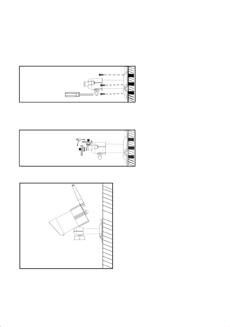
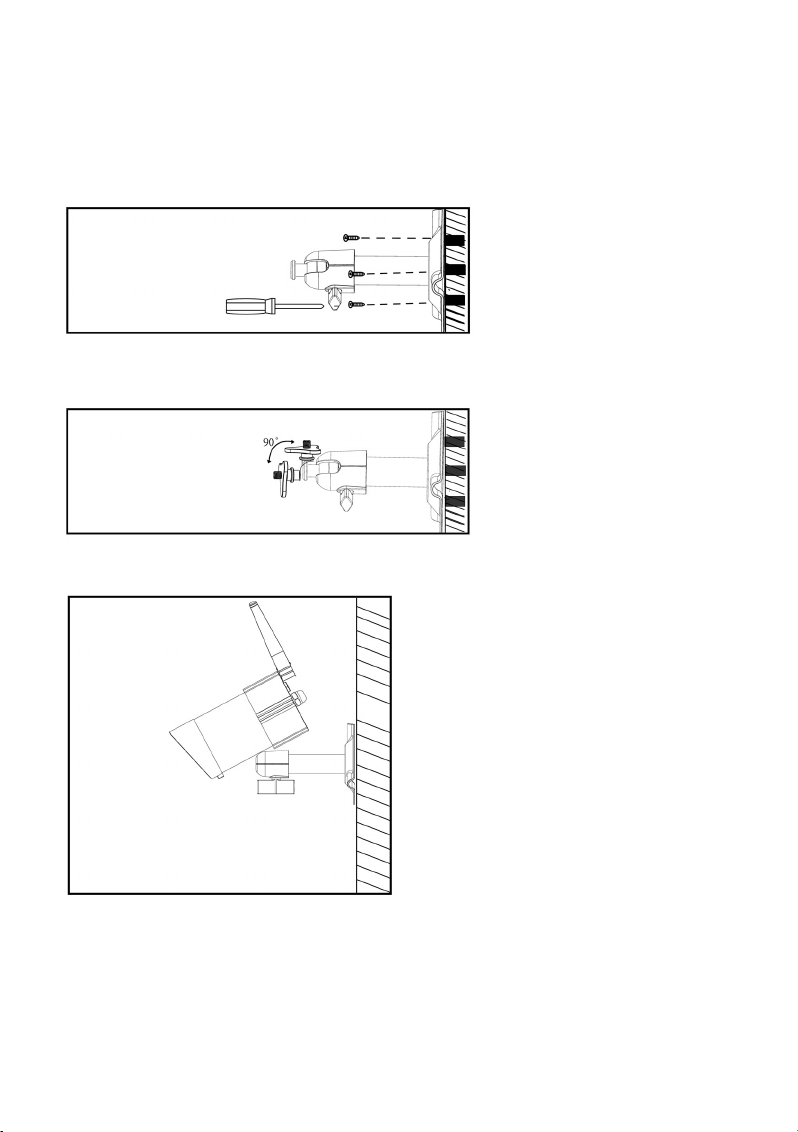
Fixieren Sie die Halterung für die
Überwachungskamera mit den
beigefügten Schrauben so an der
Wand, dass Sie das Kabel für die
Stromversorgung der Überwachungskamera durch das Wandloch ziehen können.
Es empfiehlt sich, alle Kabel im Außenbereich durch eine Kabelführung gegen Manipulationen
durch Unbefugte zu schützen.
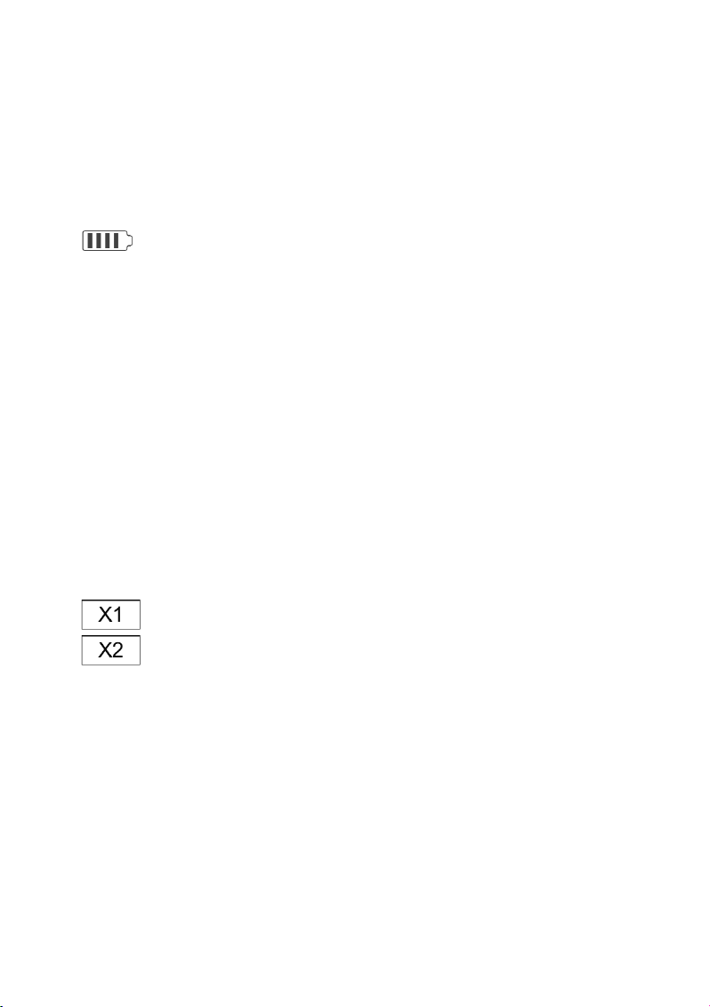
Lockern Sie an der Kamerahalterung die Fingerschraube, bis Sie
das Gewinde, an dem die Überwachungskamera fixiert wird, frei
bewegen können.
Schrauben Sie die Überwachungskamera mit dem Gewinde an der Unterseite an der Halterung fest.
Bringen Sie die Überwachungskamera in die
gewünschte Position und drehen Sie anschließend die Fingerschraube wieder fest, um die
Überwachungskamera in dieser Stellung zu
fixieren.
Page 10
10
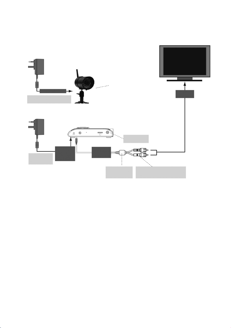
e) Kabelverbindungen
Achten Sie darauf, das Netzteil nicht versehentlich an die TV/Monitor-Ausgangsbuchse
der Inneneinheit anzuschließen!
TV/MONITOR
Zur Überwachungskamera
ÜBERWACHUNGSKAMERA
Schrauben Sie die Halterung im
Uhrzeigersinn an der Unterseite
der Überwachungskamera fest.
Eingang für
Videosignal
Hier Stromversorgung
einschalten
INNENEINHEIT (DVR/EMPFÄNGER)
Steckernetzteil zur Stromversorgung
der Überwachungskamera
Steckernetzteil für
die Stromversorgung
der Inneneinheit
Über die DC 5 V/
1 A Buchse mit
der Inneneinheit
verbinden
Über die 3,5 mm
Klinkenbuchse mit
der Inneneinheit
verbinden
Verbindungskabel
von der Inneneinheit
zum TV/Monitor
Verbinden Sie den gelben Stecker mit dem
Videoeingang und den weißen mit dem
Audio-Eingang des TV-Geräts/Monitors
Page 11
11
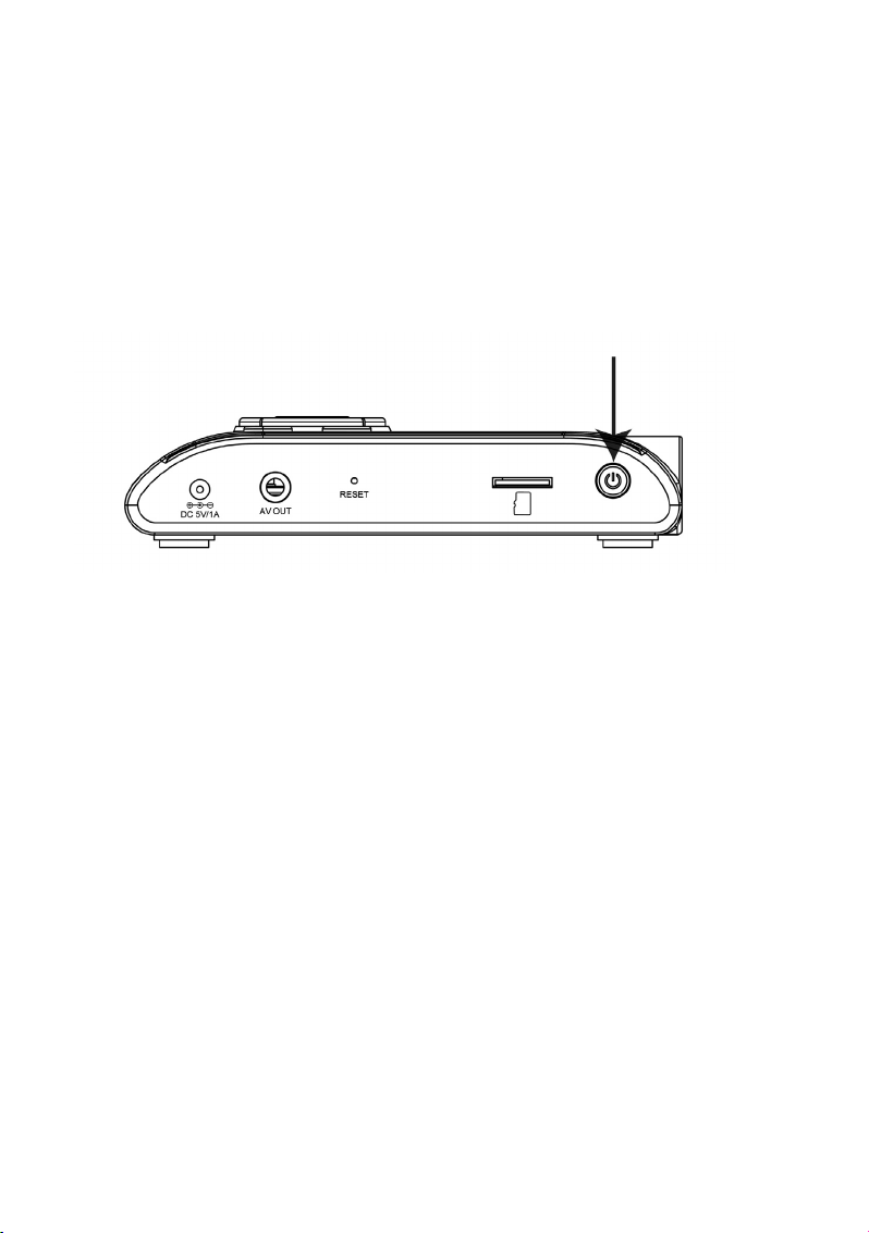
f) Inbetriebnahme des Systems
Schieben Sie die beliegende MicroSD-Speicherkarte in den dafür vorgesehenen Einschub auf der rechten Seite der Inneneinheit.
Drücken und halten Sie den Einschaltknopf am oberen Rand der Inneneinheit für etwa eine Sekunde,
um das System einzuschalten.
Drücken und halten Sie den Einschaltknopf zwei Sekunden lang, um das System auszuschalten.
Nachdem Sie das System aktiviert und auf der Inneneinheit das von der Überwachungskamera gelie-
ferte Bild geprüft haben, können Sie – falls erforderlich – die Ausrichtung der Überwachungskamera
optimieren.
g) Einstellen des Überwachungskamera-Kanals (optional)
Alle drahtlosen Überwachungskameras für dieses System sind ab Werk auf Kanal 1 voreingestellt.
☞
Falls Sie neben der beiliegenden Überwachungskamera weitere Überwachungskameras
mit der Inneneinheit dieses Sets verbinden möchten („Pairing“), stellen Sie bitte sicher,
dass jedes dieser Geräte einen anderen Kanal nutzt als die bereits installierte(n) Überwachungskamera(s).
Mit der Inneneinheit können bis zu vier drahtlose Überwachungskameras betrieben werden. Gehen Sie
vor wie in Kapitel „CAMERA SETUP“ (Überwachungskamera-Setup) beschrieben, um den MonitorKanal einer Überwachungskamera neu einzustellen.
Page 12
12
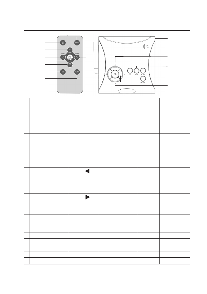
8. Bedienelemente an IR-Fernbedienung und DVR
Funktion im Display- Funktion im Playback REC-Modus Sonstiges
Modus Bildschirmmenü (Wiedergabe von
(Wiedergabe von Bildern aufgezeichneten
und Ton von der/den Daten auf der
Überwachungskamera(s) Speicherkarte)
auf dem an der Inneneinheit
angeschlossenen Monitor
1 Funk-Verbindungs-
anzeige
2 Stromversor-
gungsanzeige
3 Überwachungskamera- Pfeiltaste Vorspulen
Kanal wechseln NACH OBEN
4 LAUTSTÄRKE Pfeiltaste LAUTSTÄRKE
verringern (VOL) verringern (VOL),
Zwischen ÜberwachungskameraKanälen wechseln (CH)
5 LAUTSTÄRKE Pfeiltaste LAUTSTÄRKE
erhöhen (VOL) erhöhen (VOL)
Zwischen Kanälen
wechseln (CH)
6 MENU OK/ENTER ABSPIELEN/PAUSE
7 Kanal wechseln Pfeiltaste Zurückspulen
NACH UNTEN
8 ESC EXIT Zurück
9 REC/STOP Weiter STOP
10 ZOOM
11 ALARM
12 Einschaltknopf
Infrarot-
Fernbedienung
Inneneinheit
1
4
10
5
9
3
4
6
7
8
11
6
5
2
3
8
10
11
9
7
12
Page 13
13
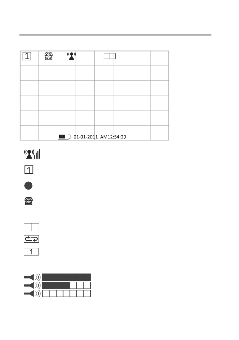
9. Systemfunktionen
a) Die Bedeutung der Symbole
1. Anzeige der Stärke des Funksignals
2. Anzeige des gewählten Überwachungskamera-Kanals
3. Anzeige für den aktivierten Aufnahme-Modus
4. Anzeige Audio-Kanal
5. Display-Modus
QUAD Display (4 Kameras gleichzeitig)
SCAN Display (Anzeige der Bilder der angeschlossenen Kameras in regelmäßigem Wechsel)
SINGLE Display (nur das Bild EINER Überwachungskamera wird angezeigt)
6. Audio-Lautstärke (7 Stufen)
= volle Lautstärke
= halbe Lautstärke
= Stummschaltung
Page 14
14
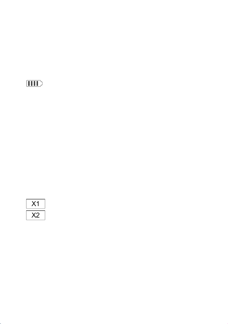
7. Inneneinheit – Stromversorgungsanzeige
Die Stromversorgungsanzeige zeigt 100 % an, wenn die Inneneinheit über das Steckernetzteil mit dem
Stromnetz verbunden oder der integrierte Akku voll aufgeladen ist.
Die Stromversorgungsanzeige stellt die verbleibende Energie durch die Anzahl der Blöcke im Batterie-
symbol dar.
Wird nur noch ein Block angezeigt, ist es notwendig, den Akku durch Anschließen des Steckernetzteils
ans Stromnetz neu aufzuladen.
Das System schaltet sich von selbst ab, wenn nicht mehr genügend Energie zur Verfügung steht.
|||| = Akku 100 % geladen bzw. Steckernetzteil angeschlossen
||| = Akku zu 70 % geladen
|| = Akku zu 50 % geladen
| = Akku zu 20 % geladen
8. Systemzeit: MM DD YYYY AM hh:mm:ss
MM = Monat (z. B. „01“ für Januar)
DD = Kalendertag (z. B. „16“)
YYYY = Jahr (z. B. „2012“)
AM = Zeitraum von 0:00 Uhr nachts bis 12:00 Uhr mittags (z. B. AM 2:25:39 = 2:25:39 Uhr früh)
PM = Zeitraum von 12:00 Uhr mittags bis 0:00 Uhr nachts (z. B. PM 2:25:39 = 14:25:39 nachmittags)
hh = aktuelle Uhrzeit: Stunde (z. B. „12“)
mm = aktuelle Uhrzeit: Minute (z. B. „25“)
ss = aktuelle Uhrzeit: Sekunde (z. B. „39“)
9. ZOOM-Anzeige
Zoom-Faktor 1
Zoom-Faktor 2
Page 15
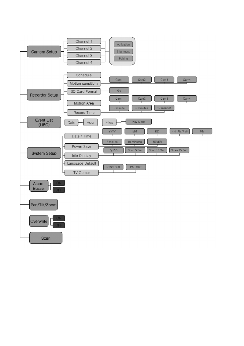
15
b) Menüstruktur der Inneneinheit
Page 16
16
10. Bedienung des Systems
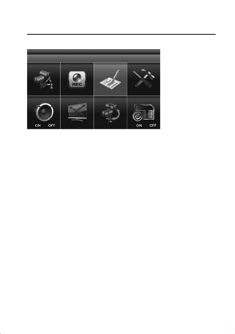
a) System-Menü (Hauptmenü)
Drücken Sie auf der Inneneinheit oder auf der Infrarot-Fernbedienung die „MENU“-Taste (6), um das
Hauptmenü aufzurufen.
Im Hauptmenü ist zunächst standardmäßig die Funktion „EVENT LIST“ markiert. Falls Sie keine weiteren Eingaben vornehmen, zeigt das System nun 2 Minuten lang das Hauptmenü an und wechselt dann
wieder zur Anzeige des Kamerabilds.
Page 17
17
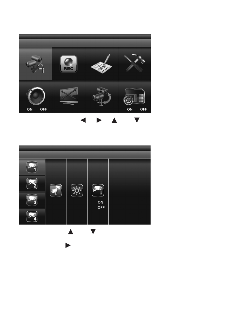
b) „CAMERA SETUP“ (Überwachungskamera-Setup)
Markieren Sie mit den Pfeiltasten (4), (5), (3) und (7) die Funktion „CAMERA SETUP“
und drücken Sie erneut die „MENU“-Taste (6), um in das Untermenü des Überwachungskamera-Setups
zu gelangen.
Nutzen Sie die Pfeiltasten (3) und (7), um die Überwachungskamera (1 – 4) auszuwählen, die
Sie konfigurieren möchten.
Nutzen Sie die Pfeiltaste (5), um die folgenden Einstellungen auszuwählen:
- „PAIRING“ (Überwachungskamera anmelden)
- „BRIGHTNESS“ (Helligkeitseinstellung für das Kamerabild)
- „CAMERA ON/OFF“ (Überwachungskamera-Kanal aktivieren/deaktivieren)
Page 18
18
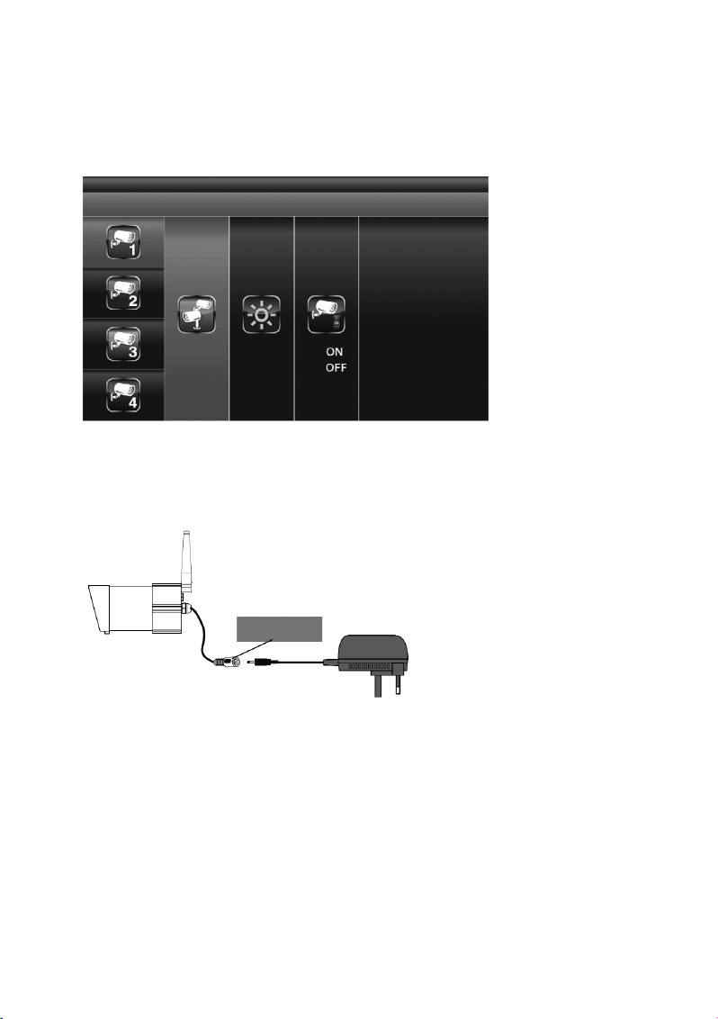
„PAIRING“ (Verbinden einer Überwachungskamera mit der Inneneinheit)
Falls Sie neben der beiliegenden Überwachungskamera weitere Überwachungskameras mit der Inneneinheit dieses Sets verbinden möchten („Pairing“), stellen Sie bitte sicher, dass jedes dieser Geräte
einen anderen Kanal nutzt als die bereits installierte(n) Überwachungskamera(s). Mit der Inneneinheit
können bis zu vier Überwachungskameras betrieben werden.
Ist „PAIRING“ markiert, drücken Sie einmal die „MENU“-Taste (6), um den Verbindungsprozess zwischen Überwachungskamera und Inneneinheit (Pairing) zu starten.
Drücken Sie anschließend die Pairing-Taste am Ende des Kamerakabels. Diese befindet sich auf dem
Verbindungsstück zum Steckernetzteil.
Dabei blinkt die Pair-LED an der Überwachungskamera einmal auf. Ein dauerhaftes Blinken der LED
signalisiert, dass eine Datenübertragung im Gange ist.
Das System bestätigt die erfolgreiche Verbindung zwischen Überwachungskamera und Inneneinheit,
indem es auf dem Bildschirm der Inneneinheit das Wort „PAIRED“ anzeigt.
Scheitert die Verbindung zwischen Überwachungskamera und Inneneinheit, zeigt das System auf dem
Bildschirm die Meldung „PAIRING FAIL“ an.
Drücken Sie die Taste „ESC“ (8), um das Menü zu verlassen.
Pairing-Taste
Page 19
19
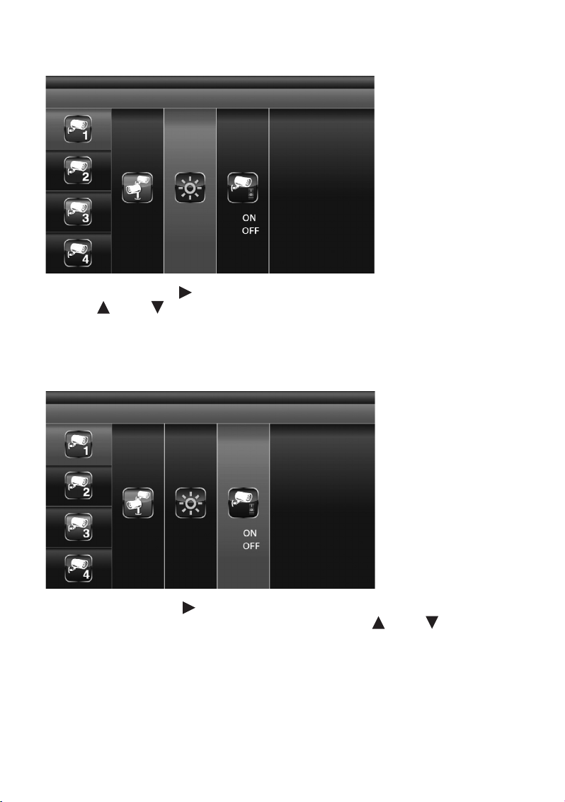
„BRIGHTNESS“ (Einstellen der Überwachungskamera-Helligkeit)
Wählen Sie mit der Pfeiltaste (5) die Funktion „BRIGHTNESS“ (Helligkeitseinstellung) aus. Mit den
Pfeiltasten (3) und (7) kann nun die Helligkeit für die Darstellung des Kamerabildes verändert
werden.
Drücken Sie die Taste „ESC“ (8), um das Menü zu verlassen.
„ACTIVATE OR DEACTIVATE“ (Aktivierung/Deaktivierung einer Überwachungskamera)
Markieren Sie mit der Pfeiltaste (5) den Menüpunkt „ACTIVATE OR DEACTIVATE“ zum Aktivieren oder
Deaktivieren der ausgewählten Überwachungskamera. Mit den Pfeiltasten (3) und (7) aktivieren
(„ON“) oder deaktivieren („OFF“) Sie die gewählte Überwachungskamera.
Drücken Sie die Taste „ESC“ (8), um das Menü zu verlassen.
☞
Das Aktivieren und Deaktivieren einer Überwachungskamera ist nur dann möglich, wenn
diese an der Inneneinheit korrekt angemeldet ist. Weitere Hinweise hierzu entnehmen Sie
dem Kapitel „PAIRING“.
Page 20
20
c) „RECORDER SETUP“ (Videorekorder-Setup)
Markieren Sie mit den Pfeiltasten (4), (5), (3) und (7) die Funktion „REC“ und drücken
Sie die „MENU“-Taste (6), um in das Untermenü des „RECORDER SETUP“ (Videorekorder-Setup) zu
gelangen.
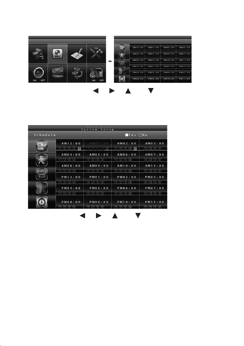
„RECORD SCHEDULE“ (Aufzeichnungszeitplan)
Nutzen Sie die Pfeiltasten (4), (5), (3) und (7), um einen Zeitpunkt für den Start einer
Videoaufzeichnung auszuwählen. Drücken Sie die „MENU“-Taste (6), um die Einstellungen des Aufzeichnungszeitplans zu verändern.
Sie haben die Wahl zwischen drei verschiedenen Aufzeichnungsvarianten. Markieren Sie zunächst den
Zeitpunkt für den Start der Videoaufzeichnung und drücken Sie anschließend einmal oder mehrmals die
„MENU“-Taste (6), um die Aufzeichnungsoptionen durchzuschalten:
M: „MOTION“ (Aufzeichnung wird nur gestartet, wenn das System eine Bewegung registriert)
S: „SCHEDULE“ (planmäßige, kontinuierliche Aufzeichnung)
C: „MANUAL“ (manuelle Aufzeichnung)
In allen drei Modi zeichnet das System Videos von allen vier Überwachungskamera-Kanälen gleichzei-
tig auf. Für den ersten der vier Kanäle ist auch eine Audio-Aufzeichnung möglich. Ein Audio-Kanal ist
jeweils im QUAD-Modus (standardmäßig ist Kanal 1 bzw. der nächste verfügbare Kanal mit einer angeschlossenen und gekoppelten Überwachungskamera (Pairing) voreingestellt), im Einzelkanal-Vollbildmodus oder im „MOTION“-Modus (Bewegungserkennung) verfügbar.
Page 21
21
Im „MOTION“-Modus wird die Tonaufzeichnung automatisch zugeschaltet, sobald das System ein sich
bewegendes Objekt wahrnimmt.
Um eine Aufzeichnung im „MANUAL“-Modus zu starten, drücken Sie einmal die Taste „REC/DEL“ (9).
Die Aufzeichnung kann frühestens 30 Sekunden nach Aufnahmestart wieder gestoppt werden. Um eine
Aufzeichnung zu beenden, drücken Sie einmal die Taste „REC/DEL“ (9).
Ꮨ
Wenn Sie die Speicherkarte aus der Inneneinheit entfernen möchten, schalten Sie das
System unbedingt vorher aus!
Im „SCHEDULE“-Modus wird das System 60 Sekunden, nachdem die Aufnahme manuell gestoppt wurde,
die Aufzeichnung automatisch wieder fortsetzen.
Im „MOTION“-Modus startet die Bewegungserkennung erneut nach 60 Sekunden, wenn die Aufzeichnung manuell beendet wurde.
Die Aufzeichnung muss beendet werden, bevor Sie das Hauptmenü aufrufen können. Erfolgt 2 Minuten
lang keine weitere Eingabe, wechselt das System automatisch in den „QUAD“-Modus zurück.
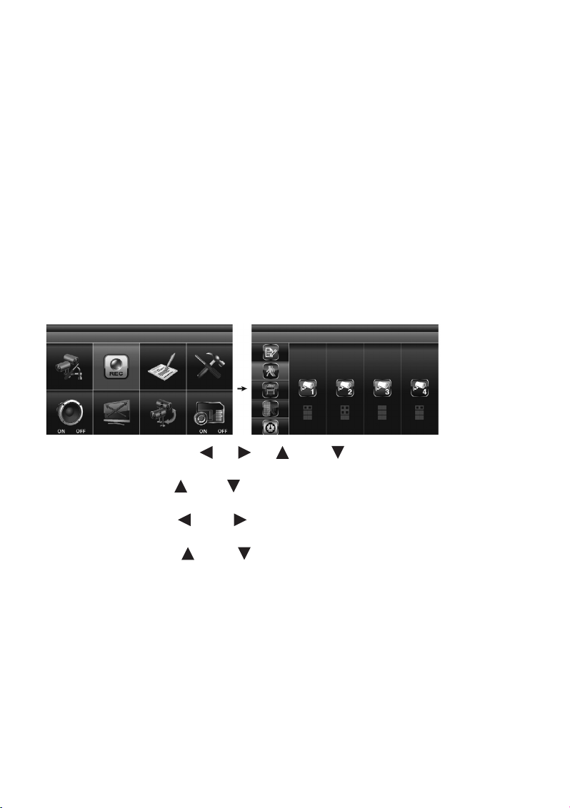
„MOTION DETECTION SENSITIVITY“ (Einstellung der Empfindlichkeit für die Bewegungserkennung)
Markieren Sie mit den Pfeiltasten (4), (5), (3) und (7) das „RECORDER SETUP“ und
drücken Sie die „MENU“-Taste (5).
Benutzen Sie die Pfeiltasten (3) und (7), um am linken Rand den Menüpunkt „MOTION DETECTION SENSITIVITY“ zur Einstellung der Empfindlichkeit für die Bewegungserkennung anzuwählen.
Benutzen Sie die Pfeiltasten (4) und (5), um in den rechten Feldern die gewünschte Überwachungskamera (1 – 4) zu markieren.
Benutzen Sie die Pfeiltasten (3) und (7), um die Empfindlichkeitsstufe anzupassen: „OFF“ /
„LV1“ / „LV2“ / „LV3“ („LV3“ ist die empfindlichste Einstellung).
Drücken Sie die „ESC“-Taste (8), um die Einstellungen zu speichern und das Menü zu verlassen.
Page 22
22
„FORMAT STORAGE“ (Speicherkarte formatieren)
Markieren Sie mit den Pfeiltasten (4), (5), (3) und (7) im Hauptmenü das „RECORDER
SETUP“ und drücken Sie die „MENU“-Taste (6).
Benutzen Sie die Pfeiltasten (3) und (7), um am linken Rand den Menüpunkt „MENU: START
FORMAT“ zur Formatierung der Speicherkarte anzuwählen.
Drücken Sie nochmals die „MENU“-Taste (6), um Ihre Eingabe zu bestätigen und mit der Formatierung
der Speicherkarte zu beginnen.
Drücken Sie die Taste „ESC“ (8), um das Menü zu verlassen.
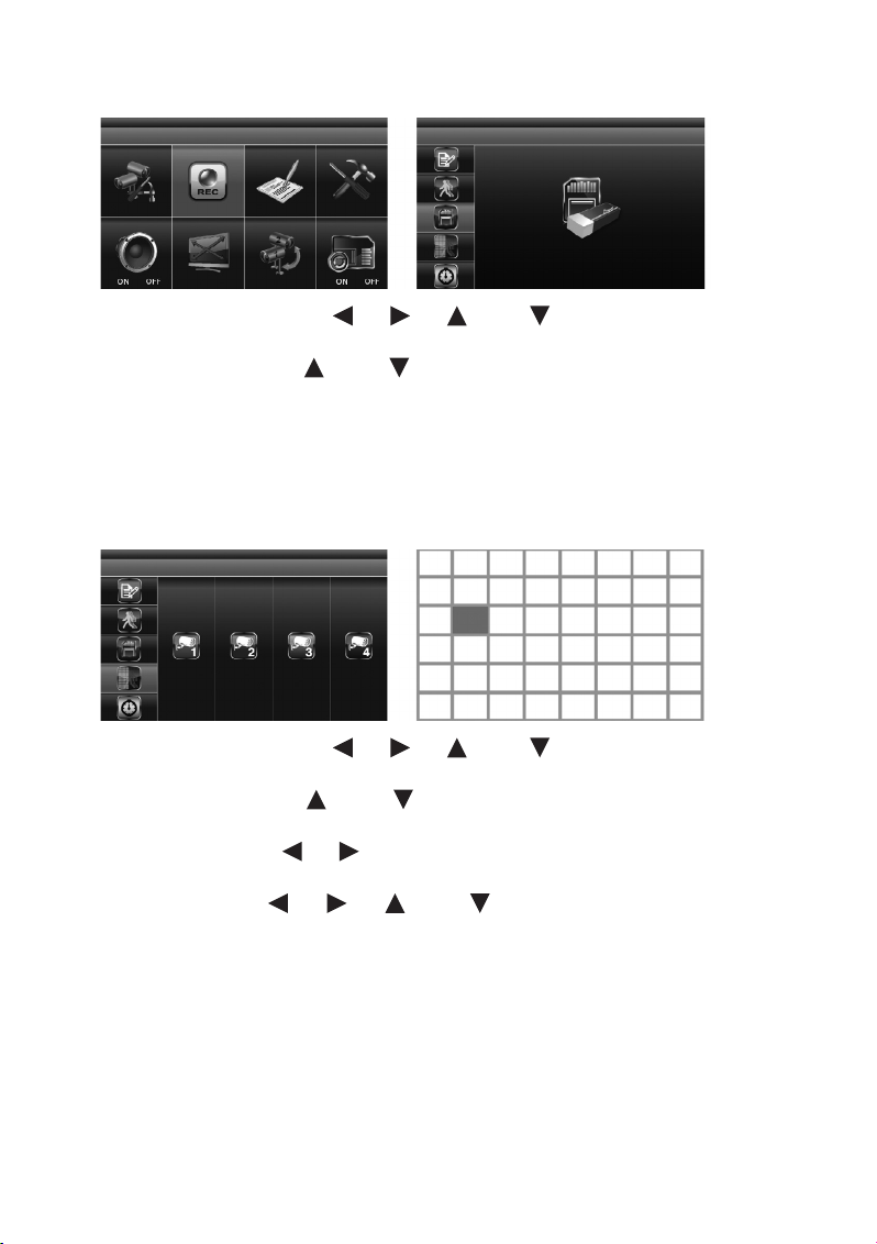
„SETUP MASKING AREA“ („Masken“-Bereich festlegen)
Markieren Sie mit den Pfeiltasten (4), (5), (3) und (7) im Hauptmenü das „RECORDER
SETUP“ und drücken Sie die „MENU“-Taste (6).
Benutzen Sie die Pfeiltasten (3) und (7), um am linken Rand den Menüpunkt „SETUP MASKING AREA“ für die Festlegung des Masken-Bereichs anzuwählen.
Nutzen Sie die Pfeiltasten (4), (5), um die gewünschte Überwachungskamera zu markieren und
drücken Sie die „MENU“-Taste (6), um Ihre Auswahl zu bestätigen.
Mit Hilfe der Pfeiltasten (4), (5), (3) und (7) wählen Sie die Bereiche des Gitternetzes
an, in denen die Bewegungserkennung nicht wirksam sein soll. Drücken Sie die „MENU“-Taste (6), um
ein Segment im Gitternetz zu maskieren oder die Maskierung aufzuheben.
☞
Bewegungen, die in den maskierten Bereichen stattfinden, werden vom System ignoriert
und lösen im „MOTION“-Modus keine Videoaufzeichnung aus.
Drücken Sie die „ESC“-Taste (8), um die Einstellungen zu speichern und das Menü zu verlassen.
Page 23
23
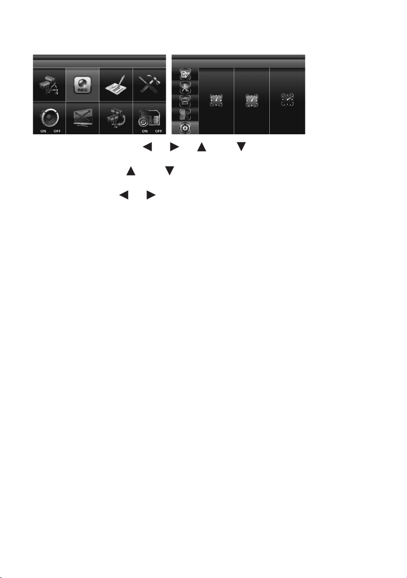
„RECORD TIME“ (Einstellung der Aufzeichnungsdauer)
Markieren Sie mit den Pfeiltasten (4), (5), (3) und (7) das „RECORDER SETUP“ und
drücken Sie die „MENU“-Taste (6).
Benutzen Sie die Pfeiltasten (3) und (7), um am linken Rand den Menüpunkt „RECORD TIME“
für die Festlegung der Dauer einer Videoaufzeichnung anzuwählen.
Nutzen Sie die Pfeiltasten (4), (5), um die gewünschte Aufzeichnungsdauer pro gespeicherter
Datei zu markieren: „2 MINUTES PER FILE“ / „5 MINUTES PER FILE“ / „10 MINUTES PER FILE“ (2, 5
oder 10 Minuten pro Datei). Drücken Sie anschließend die „MENU“-Taste (6), um Ihre Auswahl zu bestätigen.
Drücken Sie die „ESC“-Taste (8), um die Einstellungen zu speichern und das Menü zu verlassen.
Page 24
24
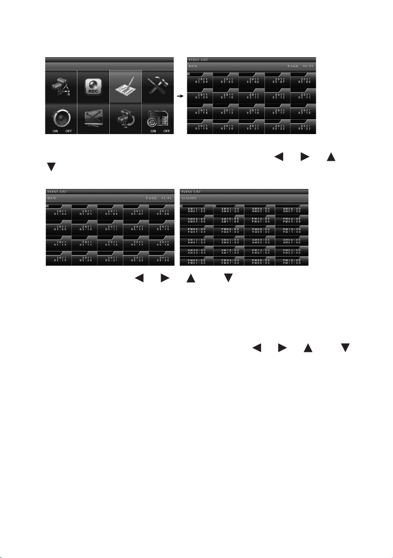
d) „EVENT LIST“ (Event-Liste)
Beim Aufrufen des Hauptmenüs mit der „MENU“-Taste (5) ist der Menüpunkt „EVENT LIST“ bereits automatisch markiert. Ist dies nicht der Fall, markieren Sie mit den Pfeiltasten (4), (5), (3) und
(7) den Menüpunkt „EVENT LIST“ und drücken erneut die „MENU“-Taste (5), um in die Event-Liste
zu gelangen.
Benutzen Sie die Pfeiltasten (4), (5), (3) und (7), um aus der Liste „DATE“ den Ordner
mit dem gewünschten Aufzeichnungsdatum anzuwählen, von dem Sie sich die gespeicherten Videoaufnahmen ansehen wollen. Das Datum wird auf den Ordnern wie folgt dargestellt:
[Jahr]
[Monat – Tag]
Drücken Sie die „MENU“-Taste (6), um Ihre Auswahl zu bestätigen und den ausgewählten Ordner zu öff-
nen. Wählen Sie aus der nun angezeigten Liste mit den Pfeiltasten (4), (5), (3) und (7)
den Ordner mit der gewünschten Stunde aus (jeder Unterordner steht für eine Stunde) und drücken Sie
die „MENU“-Taste (6) zur Bestätigung.
Jeder Ordner mit einer Videoaufzeichnung zeigt Informationen zu Aufzeichnungsbeginn und -ende
sowie zu den gewählten Überwachungskamera-Kanälen und zum Aufzeichnungsmodus an.
Page 25
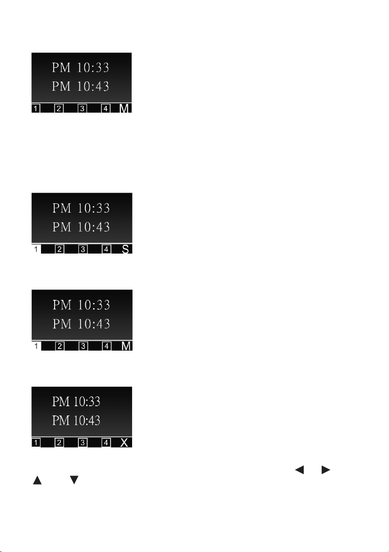
25
1. Beginn und Ende der Aufzeichnung
Start: 10:33 pm (22:33 Uhr)
Ende: 10:43 pm (22:43 Uhr)
Je nach gewähltem Wert im Menü „RECORD TIME“ enthält eine einzelne Datei eine Videoaufzeichnung
von einer Länge von 2, 5 oder 10 Minuten.
2. Aufzeichnungsmodus
Die Aufzeichnung von Überwachungskamera-Kanal 1 ist im „SCHEDULE“-Modus (S) (planmäßige, kontinuierliche Aufzeichnung) aufgenommen worden.
Die Aufzeichnung von Überwachungskamera-Kanal 1 ist im „MOTION“-Modus (M) (Bewegungserkennung) erstellt worden.
Die Aufzeichnung der Kanäle 1, 2, 3 und 4 ist im MANUELLEN Modus (X) vorgenommen worden.
Um die aufgezeichnete Datei wiederzugeben, markieren Sie diese mit den Pfeiltasten (4), (5),
(3) und (7) und drücken anschließend die „MENU“-Taste (5).
Page 26
26
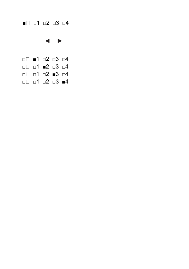
= Wiedergabe aller Überwachungskamera-Kanäle
Wenn Sie die Aufzeichnung eines einzelnen Überwachungskamera-Kanals betrachten möchten,
drücken Sie kurz nach Beginn der Wiedergabe die „MENU“-Taste (5) für PAUSE. Wählen Sie nun mit
den Pfeiltasten (4), (5) den gewünschten Überwachungskamera-Kanal aus und bestätigen Sie
Ihre Auswahl mit der „MENU“-Taste (6).
Die Kanalanzeige am linken unteren Bildschirmrand informiert Sie, welcher Kanal gerade aktiv ist:
= Kanal 1 in Vollbildanzeige
= Kanal 2 in Vollbildanzeige
= Kanal 3 in Vollbildanzeige
= Kanal 4 in Vollbildanzeige
Auf der beiliegenden CD-ROM ist die Software Sec24 Media Player enthalten, mit der Sie
die aufgezeichneten Dateien auf Ihrem Windows-PC wiedergeben können.
☞
Page 27

27
e) „SYSTEM SETUP“ (System-Setup)
Markieren Sie mit den Pfeiltasten (4), (5), (3) und (7) die Funktion „SYSTEM SETUP“
und drücken Sie erneut die „MENU“-Taste (6), um in das Untermenü „DATE AND TIME“ zu gelangen.
„DATE AND TIME“ (Datum und Uhrzeit)
Mit den Pfeiltasten (3) und (7) markieren Sie im Auswahlmenü am linken Bildschirmrand „DATE
AND TIME“ (Datum und Uhrzeit) und drücken die „MENU“-Taste (6).
Wählen Sie mit den Pfeiltasten (4), (5) nacheinander die Einstellungen für „YYYY“ (Jahr), „MM“
(Monat), „DD“ (Tag), „PM“ bzw. „AM“ (Uhrzeit/Stunde) und „MM“ (Uhrzeit/Minuten) an und stellen Sie mit
den Pfeiltasten (3) und (7) die korrekten Werte ein. Haben Sie einen Wert richtig eingestellt,
bestätigen Sie die Eingabe jeweils mit der „MENU“-Taste (6).
Drücken Sie die „ESC“-Taste (8), um die Einstellungen zu speichern und das Menü zu verlassen.
Page 28
28
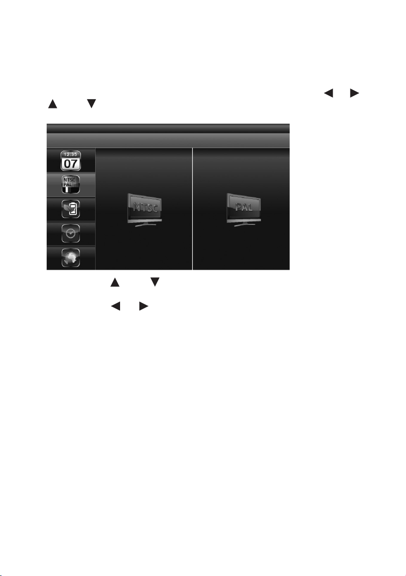
„TV OUTPUT“ (TV-Ausgang: NTSC/PAL)
☞
Benutzen Sie das beiliegende A/V-Kabel, um das System bei Bedarf an einen Monitor oder
an ein TV-Gerät anzuschließen. Beachten Sie hierbei die Hinweise in Abschnitt 7e („Installation/Kabelverbindungen“).
Drücken Sie die „MENU“-Taste (6) und markieren Sie im Hauptmenü mit den Pfeiltasten (4), (5),
(3) und (7) den Menüpunkt „SYSTEM SETUP“ (rechts oben). Drücken Sie erneut die „MENU“-
Taste (6), um Ihre Auswahl zu bestätigen.
Mit den Pfeiltasten (3) und (7) markieren Sie im Auswahlmenü am linken Bildschirmrand „TV
OUTPUT“ und drücken die „MENU“-Taste (6).
Mit den Pfeiltasten (4), (5) markieren Sie je nach System NTSC oder PAL und drücken die
„MENU“-Taste (6) zur Bestätigung Ihrer Eingabe.
Drücken Sie die „ESC“-Taste (8), um die Einstellungen zu speichern und das Menü zu verlassen.
☞
Durch einen Wechsel des TV-Systems kann sich die Bildschirmdarstellung verändern.
Page 29
29
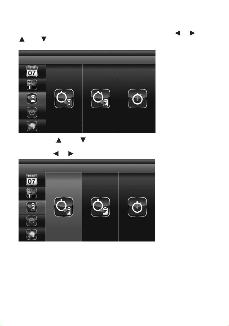
„POWER SAVING“ (Energiespar-Modus)
Drücken Sie die „MENU“-Taste (5) und markieren Sie im Hauptmenü mit den Pfeiltasten (4), (5),
(3) und (7) den Menüpunkt „SYSTEM SETUP“ (rechts oben). Drücken Sie erneut die „MENU“-
Taste (6), um Ihre Auswahl zu bestätigen.
Mit den Pfeiltasten (3) und (7) markieren Sie im Auswahlmenü am linken Bildschirmrand
„POWER SAVING“ und drücken die „MENU“-Taste (6).
Mit den Pfeiltasten (4), (5) markieren Sie eine der folgenden Optionen:
Die Bildschirmanzeige schaltet sich aus, wenn 5 Minuten lang keine Eingabe erfolgt ist.
Page 30

30
Die Bildschirmanzeige schaltet sich aus, wenn 10 Minuten lang keine Eingabe erfolgt ist.
Der Bildschirm bleibt dauernd aktiviert.
Drücken die „MENU“-Taste (6) zur Bestätigung Ihrer Eingabe.
Drücken Sie die „ESC“-Taste (8), um die Einstellungen zu speichern und das Menü zu verlassen.
Page 31

31
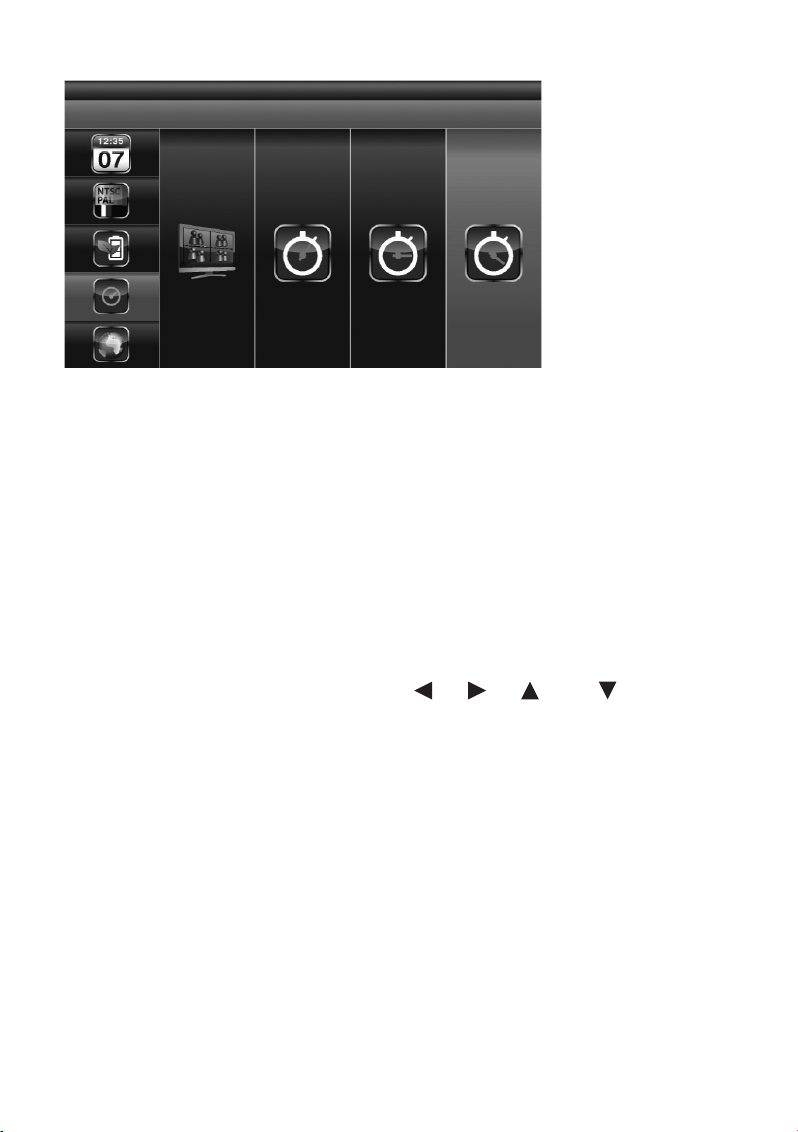
„MULTI CHANNELS IDLE DISPLAY“ (Bildschirmdarstellung in Phasen, in denen weder Videoaufzeichnungen noch Benutzereingaben stattfinden)
Über diese Option legen Sie für jeden Überwachungskamera-Kanal den Betriebsmodus für den Fall fest,
dass Sie für längere Zeit keine Eingaben machen und gerade keine Videoaufzeichnung aktiv ist.
Drücken Sie die „MENU“-Taste (6) und markieren Sie im Hauptmenü mit den Pfeiltasten (4), (5),
(3) und (7) den Menüpunkt „SYSTEM SETUP“ (rechts oben). Drücken Sie erneut die „MENU“-
Taste (5), um Ihre Auswahl zu bestätigen.
Mit den Pfeiltasten (3) und (7) markieren Sie im Auswahlmenü am linken Bildschirmrand
„MULTI CHANNELS IDLE DISPLAY“ und drücken die „MENU“-Taste (6).
Wählen Sie mit den Pfeiltasten (4), (5) zwischen folgenden Optionen:
QUAD-Modus: Der vierfach geteilte Bildschirm stellt die Bilder aus allen vier ÜberwachungskameraKanälen gleichzeitig dar.
Page 32

32
Auf dem Monitor werden die Bilder der angeschlossenen Überwachungskameras im „SCAN“-Modus
nacheinander immer wieder im Wechsel jeweils 5 Sekunden lang dargestellt.
Auf dem Monitor werden die Bilder der angeschlossenen Überwachungskameras im „SCAN“-Modus
nacheinander immer wieder im Wechsel jeweils 10 Sekunden lang dargestellt.
Page 33
33
Auf dem Monitor werden die Bilder der angeschlossenen Überwachungskameras im „SCAN“-Modus
nacheinander immer wieder im Wechsel jeweils 15 Sekunden lang dargestellt.
Bestätigen Sie Ihre Eingabe durch Drücken der „MENU“-Taste (6).
Drücken Sie die „ESC“-Taste (8), um die Einstellungen zu speichern und das Menü zu verlassen.
☞
Die Aktivierung und Deaktivierung von Kameras im „CAMERA SETUP“ (Überwachungskamera-Setup, siehe Kapitel 10b) beeinflusst, von welchen Kanälen im Ruhezustand Bilder
auf dem Monitor dargestellt werden.
Ein Audio-Kanal ist jeweils im QUAD-Modus (standardmäßig ist Kanal 1 bzw. der nächste verfügbare Kanal mit einer angeschlossenen und gekoppelten Überwachungskamera (Pairing)
voreingestellt), im Einzelkanal-Vollbildmodus oder im „MOTION“-Modus (Bewegungserkennung) verfügbar.
Der Audio-Kanal bleibt so lange verbunden, bis der Kanal gewechselt wird.
Sind für die Funktion „MULTI CHANNELS IDLE DISPLAY“ 5/10/15-Sekunden-Intervalle
eingestellt, wählen Sie mit den Pfeiltasten (4), (5), (3) und (7) im Hauptmenü die Option „SCAN ACTIVATED CAMERAS“, um diesen Darstellungsmodus zu aktivieren.
Page 34
34
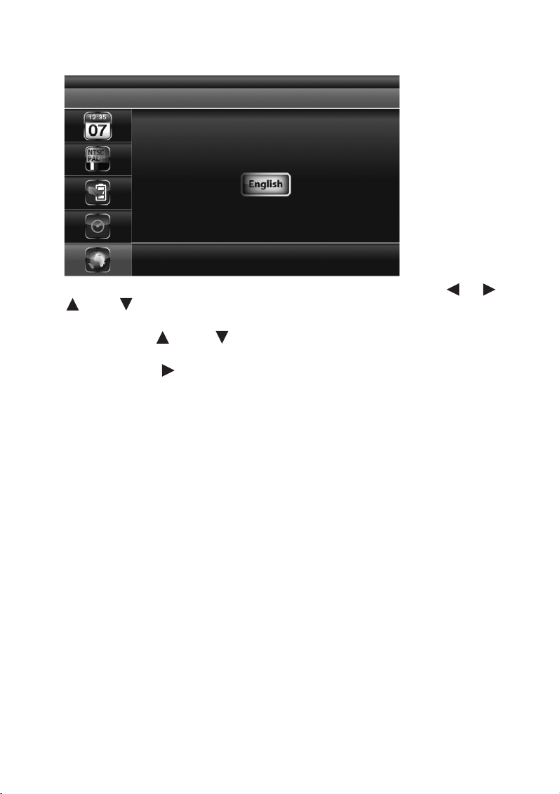
„DEFAULT“ (Standardeinstellungen wiederherstellen)
Drücken Sie die „MENU“-Taste (6) und markieren Sie im Hauptmenü mit den Pfeiltasten (4), (5),
(3) und (7) den Menüpunkt „SYSTEM SETUP“ (rechts oben). Drücken Sie erneut die „MENU“-
Taste (6), um Ihre Auswahl zu bestätigen.
Mit den Pfeiltasten (3) und (7) markieren Sie im Auswahlmenü am linken Bildschirmrand
„DEFAULT“ und drücken die „MENU“-Taste (6).
Mit Hilfe der Pfeiltaste (5) wählen Sie die Spracheinstellung für die Systemwiederherstellung, drücken
die „MENU“-Taste (6) und starten so die Wiederherstellung der werksseitigen Standardeinstellungen.
Page 35

35
f) „ALARM BUZZER“ (Akustischer Alarm)
Drücken Sie die „MENU“-Taste (6) und markieren Sie im Hauptmenü mit den Pfeiltasten (4), (5),
(3) und (7) den Menüpunkt „ALARM BUZZER“ (links unten).
Registriert die Überwachungskamera ein sich bewegendes Objekt, wird vom Monitor standardmäßig ein
Alarmton ausgegeben. Durch Drücken der „MENU“-Taste (5) lässt sich der Alarm einschalten („ON“) und
ausschalten („OFF“).
Page 36

36
g) PAN TILT ZOOM“ (Auf dem Monitor dargestellten Bildausschnitt der
Überwachungskamera schwenken, kippen oder zoomen)
Drücken Sie die „MENU“-Taste (6) und markieren Sie im Hauptmenü mit den Pfeiltasten (4), (5),
(3) und (7) die Funktion „PAN TILT ZOOM“ und drücken Sie erneut die „MENU“-Taste (5), um in
den „PAN TILT ZOOM“-Modus zu gelangen.
☞
Die Überwachungskamera selbst kann nicht geschwenkt werden. Über die Funktion „PAN
TILT ZOOM“ lässt sich lediglich der auf dem Display der Inneneinheit dargestellte Bildausschnitt verändern.
Drücken Sie im „PAN TILT ZOOM“-Modus erneut die „MENU“-Taste (6), um für das Bild der gewählten
Überwachungskamera die zweite Zoom-Stufe zu aktivieren. Durch mehrmaliges Drücken der Pfeiltasten
(4), (5), (3) und (7) lässt sich anschließend der angezeigte Bildausschnitt in kleinen
Schritten nach links, rechts, oben oder unten verändern.
Drücken Sie erneut die „MENU“-Taste (6), um wieder herauszuzoomen.
In Zoom-Stufe 1 können Sie mit den Pfeiltasten (3) und (7) zwischen den einzelnen Überwa-
chungskamera-Kanälen hin- und herschalten.
Drücken Sie die „ESC“-Taste (8), um den „ZOOM“-Modus zu beenden.
Page 37

37
h) „SCAN ACTIVATED CAMERAS“ („SCAN“-Modus)
Drücken Sie die „MENU“-Taste (6) und markieren Sie im Hauptmenü mit den Pfeiltasten (4), (5),
(3) und (7) die Funktion „SCAN ACTIVATED CAMERAS“ und drücken Sie erneut die „MENU“Taste (6), um in den „SCAN“-Modus für die aktivierten Überwachungskameras einzuschalten. Im
„SCAN“-Modus wechselt das System auf dem Display der Inneneinheit in regelmäßigen Zeitintervallen
die aktuellen Bilder der aktivierten Überwachungskameras durch.
☞
Die „ON“/“OFF“-Einstellungen, mit denen Sie im „CAMERA SETUP“ des Hauptmenüs die
angeschlossenen Überwachungskameras aktiviert oder deaktiviert haben, beeinflussen,
welche Bilder im Ruhezustand des Monitors von welchen Überwachungskameras dargestellt werden („SCAN ACTIVATED CAMERAS“).
Im Kapitel „MULTI CHANNELS IDLE DISPLAY“ finden Sie Hinweise, wie Sie die Zeitintervalle für die Bildschirmdarstellung im „SCAN“-Modus anpassen können.
Während einer Videoaufzeichnung aktiviert das System automatisch den „QUAD“-Modus.
Page 38

38
i) „MEMORY CARD OVERWRITE“ (Speicherkarte überschreiben)
Durch Aktivieren der Funktion „MEMORY CARD OVERWRITE“ ist es möglich, die ältesten Dateien mit
den neuesten Aufzeichnungen zu überschreiben, falls die Speicherkarte über nicht mehr ausreichend
Speicherplatz für neue Aufnahmen verfügt.
Markieren Sie im Hauptmenü mit den Pfeiltasten (4), (5), (3) und (7) die Funktion
„MEMORY CARD OVERWRITE“ und drücken Sie erneut die „MENU“-Taste (6), um das Überschreiben der
Daten auf der Speicherkarte einzuschalten („ON“) oder auszuschalten („OFF“).
Bei eingelegter Speicherkarte wird der verbleibende Speicherplatz angezeigt, z. B. „1.89 GB
space available on memory card“.
Fehlt die Speicherkarte, ist sie schreibgeschützt oder beschädigt, zeigt das System statt
des verbleibenden Speicherplatzes eine ERROR-Meldung aus.
Ist die Speicherkarte voll, gibt das System die Meldung „MEMORY FULL PLEASE FORMAT“ aus, falls „MEMORY CARD OVERWRITE“ im Hauptmenü nicht aktiviert ist („OFF“).
☞
Page 39

39
11. Wiedergabe-Software: Sec24 Media Player
Der Sec24 Media Player ist eigens dafür entwickelt worden, die Aufzeichnungen des Videoüberwachungssystems mit 2,4 GHz Digital-Funk-Farbkamera und Funkempfänger auf dem PC wiederzugeben.
Andere Anwender können Ihre Aufzeichnungen nicht ohne den Sec24 Media Player wiedergeben – dies
ist eine Vorsichtsmaßnahme, die dazu beiträgt, Ihre Daten und Ihre Privatsphäre zu schützen.
a) Die Bedienelemente des Sec24 Media Player
1. Überwachungskamera-Kanal 1 Wiedergabebereich
2. Überwachungskamera-Kanal 2 Wiedergabebereich
3. Überwachungskamera-Kanal 3 Wiedergabebereich
4. Überwachungskamera-Kanal 4 Wiedergabebereich
5. Wiedergabefortschritts-Balken
6. Wiedergabe
7. Pause
8. Stop
9. Schneller Rücklauf
10. Schneller Vorlauf
11. „Load“: Datei mit Videoaufzeichnung laden
12. Letzte Datei erneut wiedergeben
13. „Channel“: Kamerakanäle aktivieren/deaktivieren
Page 40

40
b) Installation des Sec24 Media Players (MS Windows)
Legen Sie die mit dem 2,4 GHz Digital-Funk-DVR-Monitor-Set ausgelieferte CD-ROM in das CD-ROM-
Laufwerk Ihres PCs ein.
Klicken Sie doppelt auf das Symbol „Computer“ auf Ihrem Desktop und anschließend auf das Symbol
Ihres CD-ROM-Laufwerks, um den entsprechenden Ordner zu öffnen. Sie finden dort eine Installations-
datei mit der Bezeichnung „Sec24 Media Player“. (Möglicherweise ist im Dateinamen auch die aktuelle
Versionsnummer des Programms mit enthalten.)
Folgen Sie nun den Anweisungen auf dem Bildschirm, um die Installation durchzuführen.
A. Führen Sie einen Doppelklick auf das Dateisymbol aus, um die Installation zu starten.
1. Falls Sie das Betriebssystem Windows 7 auf Ihrem Rechner installiert haben, klicken Sie
bitte mit der rechten Maustaste auf das Symbol der Datei mit dem Namen „Sec24 Media
Player“ und wählen mit einem Klick auf die linke Maustaste den Menüpunkt „Als Administrator ausführen“, um die Installation des Sec24 Media Players zu starten.
2. Falls Sie die Installation ohne Administratorrechte starten, erscheint möglicherweise die folgende
Fehlermeldung:
Page 41

41
Bei einem erfolgreichen Start der Installation erscheint folgende Meldung auf dem Bildschirm:
B. Klicken Sie auf „Next“ bzw. „Weiter“, um den Installationsprozess fortzusetzen.
Page 42
42
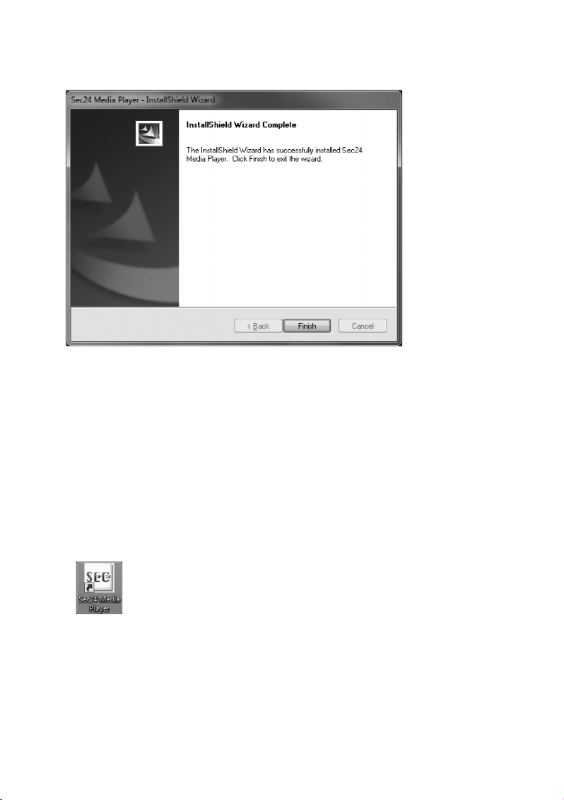
C. Sobald die Installation abgeschlossen ist, erscheint die folgende Bildschirmmeldung. Klicken Sie auf
„Finish“ bzw. „Beenden“, um das Fenster zu schließen.
c) Datei(en) mit Videoaufzeichnungen auf dem PC wiedergeben
1. Entnehmen Sie die MicroSD-Speicherkarte aus dem Einschub der Inneneinheit Ihres Videoüberwachungssystems und stecken Sie die Speicherkarte in einen entsprechenden Kartenleser Ihres PCs.
Sollte Ihr PC über keinen MicroSD-Einschub verfügen, schieben Sie die MicroSD-Speicherkarte bitte in den mitgelieferten SD-Adapter und stecken diesen anschließend in den
entsprechenden Kartenleser Ihres PCs.
Ihr PC erkennt die Speicherkarte automatisch, weist ihr einen Laufwerksbuchstaben (z. B. „E:“) zu
und zeigt sie unter in Windows in der Laufwerksliste als Wechseldatenträger an.
2. Klicken Sie mit der linken Maustaste doppelt auf das Sec24-Symbol auf Ihrem Windows-Desktop, um
die Media-Player-Software zu starten.
Page 43

43
3. Klicken Sie anschließend auf „Load“, um Videoaufzeichnungen zu laden.
4. Wählen Sie aus der nun angezeigten Laufwerksliste zunächst die Speicherkarte (z. B. Wechseldatenträger E:) aus und klicken Sie doppelt auf das Symbol, um sich die gespeicherten Video-Dateien (mit
der Endung „.SNX“) anzeigen zu lassen. Markieren Sie die gewünschte .SNX-Datei mit einem Mausklick und klicken Sie dann auf „Open“ bzw. „Öffnen“, um die Wiedergabe zu starten.
Page 44

44
d) Kanäle aktivieren und deaktivieren
Bei der Wiedergabe sind standardmäßig alle vier Überwachungskamera-Kanäle und der Audiokanal
aktiv. Bei Bedarf können Sie einzelne Kanäle gezielt manuell deaktivieren:
Entfernen Sie dazu jeweils mit einem Linksklick die Häkchen aus den entsprechenden Kästchen für:
• Audio
• 1: Video-Kanal 1
• 2: Video-Kanal 2
• 3. Video-Kanal 3
• 4. Video-Kanal 4
Page 45

45
12. Konformitätserklärung (DOC)
Hiermit erklären wir, Conrad Electronic, Klaus-Conrad-Straße 1, D-92240 Hirschau, dass sich dieses
Produkt in Übereinstimmung mit den grundlegenden Anforderungen und den anderen relevanten Vorschriften der Richtlinie 1999/5/EG befindet.
☞
Die Konformitätserklärung (DOC) zu diesem Produkt finden Sie unter www.conrad.com.
13. Wartung und Reinigung
Das Produkt ist für Sie wartungsfrei, zerlegen Sie es niemals. Für eine Reinigung genügt ein trockenes,
sauberes und weiches Tuch; trennen Sie das Produkt vor einer Reinigung von der Stromversorgung,
ziehen Sie das Steckernetzteil aus der Netzsteckdose. Reinigen Sie die Linse sehr vorsichtig, damit
keine Kratzspuren auftreten. Verwenden Sie keine aggressiven Reinigungsmittel, dadurch kommt es zu
Verfärbungen des Gehäuses. Drücken Sie nicht zu stark auf das Display der Inneneinheit, da es andernfalls zu Kratzspuren oder zu einer Beschädigung des Displays kommen kann.
14. Beseitigung von Störungen
Problem Lösung
Die Überwachungskamera Das Steckernetzteil der Inneneinheit oder der Überwachungsliefert kein Bild. kamera(s) ist nicht an die Stromversorgung angeschlossen. Die
Überwachungskamera ist außerhalb der Funk-Reichweite der
Inneneinheit installiert. Verringern Sie die Entfernung zwischen
Überwachungskamera und Inneneinheit.
Schlechte Bildqualität. Säubern Sie die Linse der Überwachungskamera.
Nachts wird nur ein weißes Die Infrarot-LEDs der Überwachungskamera zeigen sonst
Bild angezeigt. unsichtbares Licht an, das von Oberflächen wie Glas reflektiert
wird. Platzieren Sie die Überwachungskamera vor dem Fenster
oder an einer anderen Stelle.
Page 46

46
15. Entsorgung
a) Produkt
Elektronische Geräte sind Wertstoffe und dürfen nicht in den Hausmüll! Entsorgen Sie das
Produkt am Ende seiner Lebensdauer gemäß den geltenden gesetzlichen Bestimmungen.
Entnehmen Sie eine evtl. eingelegte Batterie und entsorgen Sie diese getrennt vom Produkt.
b) Batterien und Akkus
Sie als Endverbraucher sind gesetzlich (Batterieverordnung) zur Rückgabe aller gebrauchten Batterien
und Akkus verpflichtet; eine Entsorgung über den Hausmüll ist untersagt!
Schadstoffhaltige Batterien/Akkus sind mit dem nebenstehenden Symbol gekennzeichnet,
das auf das Verbot der Entsorgung über den Hausmüll hinweist.
Die Bezeichnungen für das ausschlaggebende Schwermetall sind: Cd = Cadmium, Hg =
Quecksilber, Pb = Blei (Bezeichnung steht auf den Batterien/Akkus z. B. unter dem links
abgebildeten Mülltonnen-Symbol).
Ihre verbrauchten Batterien/Akkus können Sie unentgeltlich bei den Sammelstellen Ihrer Gemeinde,
unseren Filialen oder überall dort abgeben, wo Batterien/Akkus verkauft werden! Sie erfüllen damit die
gesetzlichen Verpflichtungen und leisten Ihren Beitrag zum Umweltschutz.
16. Technische Daten
a) Überwachungskamera
Max. Anzahl Kanäle. . . . . . . . . . . . . . . . . . . . . . 1
Reichweite drahtlose Datenübertragung. . . . . . 150 m im freien Raum
Kameraauflösung . . . . . . . . . . . . . . . . . . . . . . . 640 x 480
Sendefrequenz . . . . . . . . . . . . . . . . . . . . . . . . . 2,4 GHz
Betriebstemperatur . . . . . . . . . . . . . . . . . . . . . . -10 °C ~ +50 °C
Betriebsspannung . . . . . . . . . . . . . . . . . . . . . . . 5 V/ DC, 1 A
Stromverbrauch. . . . . . . . . . . . . . . . . . . . . . . . . IR OFF: 165±20 mA
IR ON: 465±20 mA
Nachtsicht Reichweite (IR-LEDs) . . . . . . . . . . . 5 – 8 m
Schutzart . . . . . . . . . . . . . . . . . . . . . . . . . . . . . . IP66 (für den Außenbereich geeignet)
Abmessungen . . . . . . . . . . . . . . . . . . . . . . . . . . 124 x 61 x 67 mm
Page 47

47
b) DVR/Monitor Inneneinheit
Max. Anzahl Kanäle. . . . . . . . . . . . . . . . . . . . . . 4
Reichweite drahtlose Datenübertragung. . . . . . 150 m im freien Raum
Bildschirmauflösung . . . . . . . . . . . . . . . . . . . . . 320 x 240
Aufzeichnungsdauer . . . . . . . . . . . . . . . . . . . . . 2 Min., 5 Min., 10 Min.
Mindestaufzeichnungszeit. . . . . . . . . . . . . . . . . 30 Sek.
Dateiformat Aufzeichnungen. . . . . . . . . . . . . . . MP4, Dateiformat .SNX
Betriebstemperatur . . . . . . . . . . . . . . . . . . . . . . 0 °C bis +40 °C
Betriebsspannung . . . . . . . . . . . . . . . . . . . . . . . 5 V/DC, 1 A
Stromverbrauch. . . . . . . . . . . . . . . . . . . . . . . . . 220±20 mA
Integrierter Kartenleser . . . . . . . . . . . . . . . . . . . microSD, microSDHC, max. 32 GB
Eingebauter Akku . . . . . . . . . . . . . . . . . . . . . . . N/A
Abmessungen . . . . . . . . . . . . . . . . . . . . . . . . . . 113 x 113 x 26 mm
c) Steckernetzteil
Stromversorgung. . . . . . . . . . . . . . . . . . . . . . . . 100 - 240 V/AC, 50/60 Hz
Ausgang . . . . . . . . . . . . . . . . . . . . . . . . . . . . . . 5 V/DC, 1 A
d) Aufzeichnungskapazität von Speicherkarten (max. 32 GB)
☞
Die angegebenen Aufzeichnungskapazitäten sind abhängig von der Komprimierbarkeit der
Bilddaten und können deshalb in der Praxis abweichen.
1 GB microSD . . . . . . . . . . . . . . . . . . . . . . . . . . 60 min
2 GB microSD . . . . . . . . . . . . . . . . . . . . . . . . . . 110 min
8 GB microSDHC . . . . . . . . . . . . . . . . . . . . . . . 400 min
16 GB microSDHC . . . . . . . . . . . . . . . . . . . . . . 950 min
32 GB microSDHC . . . . . . . . . . . . . . . . . . . . . . 1.880 min
Page 48

48
Table of Contents
Page
1. Introduction. . . . . . . . . . . . . . . . . . . . . . . . . . . . . . . . . . . . . . . . . . . . . . . . . . . . . . . . . . . . . . . . . . . 50
2. Intended Use . . . . . . . . . . . . . . . . . . . . . . . . . . . . . . . . . . . . . . . . . . . . . . . . . . . . . . . . . . . . . . . . . 51
3. Scope of Delivery . . . . . . . . . . . . . . . . . . . . . . . . . . . . . . . . . . . . . . . . . . . . . . . . . . . . . . . . . . . . . . 51
4. Explanation of Symbols . . . . . . . . . . . . . . . . . . . . . . . . . . . . . . . . . . . . . . . . . . . . . . . . . . . . . . . . . 52
5. Safety Information. . . . . . . . . . . . . . . . . . . . . . . . . . . . . . . . . . . . . . . . . . . . . . . . . . . . . . . . . . . . . . 52
6. Best Placement of Cameras, Indoor Unit and Monitor . . . . . . . . . . . . . . . . . . . . . . . . . . . . . . . . . . 53
7. Installation. . . . . . . . . . . . . . . . . . . . . . . . . . . . . . . . . . . . . . . . . . . . . . . . . . . . . . . . . . . . . . . . . . . . 54
a) Notes. . . . . . . . . . . . . . . . . . . . . . . . . . . . . . . . . . . . . . . . . . . . . . . . . . . . . . . . . . . . . . . . . . . . . 54
b) Position of the Surveillance Camera . . . . . . . . . . . . . . . . . . . . . . . . . . . . . . . . . . . . . . . . . . . . . 54
c) Night-View Function . . . . . . . . . . . . . . . . . . . . . . . . . . . . . . . . . . . . . . . . . . . . . . . . . . . . . . . . . 54
d) Installation of the Surveillance Camera(s). . . . . . . . . . . . . . . . . . . . . . . . . . . . . . . . . . . . . . . . . 54
e) Cable Connections . . . . . . . . . . . . . . . . . . . . . . . . . . . . . . . . . . . . . . . . . . . . . . . . . . . . . . . . . . 56
f) System Commissioning. . . . . . . . . . . . . . . . . . . . . . . . . . . . . . . . . . . . . . . . . . . . . . . . . . . . . . . 57
g) Setting of the Surveillance Camera Channel (Optional) . . . . . . . . . . . . . . . . . . . . . . . . . . . . . . 57
8. Operating Elements of the Indoor Unit (DVR/Monitor) and the Infrared Remote Control. . . . . . . . 58
9. System Functions . . . . . . . . . . . . . . . . . . . . . . . . . . . . . . . . . . . . . . . . . . . . . . . . . . . . . . . . . . . . . . 59
a) Meaning of the Icons on the Display . . . . . . . . . . . . . . . . . . . . . . . . . . . . . . . . . . . . . . . . . . . . . 59
b) Menu Structure of the Indoor Unit . . . . . . . . . . . . . . . . . . . . . . . . . . . . . . . . . . . . . . . . . . . . . . . 61
10. System Operation. . . . . . . . . . . . . . . . . . . . . . . . . . . . . . . . . . . . . . . . . . . . . . . . . . . . . . . . . . . . . . 62
a) System Menu . . . . . . . . . . . . . . . . . . . . . . . . . . . . . . . . . . . . . . . . . . . . . . . . . . . . . . . . . . . . . . 62
b) "CAMERA SETUP" (Surveillance Camera Setup). . . . . . . . . . . . . . . . . . . . . . . . . . . . . . . . . . . 63
"PAIRING" (Connecting a Surveillance Camera to the Indoor Unit) . . . . . . . . . . . . . . . . . . . . . 64
"BRIGHTNESS" (Setting the Surveillance Camera Brightness) . . . . . . . . . . . . . . . . . . . . . . . . 65
"ACTIVATE OR DEACTIVATE" (Activating/Deactivating a Surveillance Camera) . . . . . . . . . . 65
c) "RECORDER SETUP" (Video Recorder Setup) . . . . . . . . . . . . . . . . . . . . . . . . . . . . . . . . . . . . 66
"RECORD SCHEDULE" (Recording Schedule) . . . . . . . . . . . . . . . . . . . . . . . . . . . . . . . . . . . . 66
"MOTION DETECTION SENSITIVITY" (Setting the Sensitivity for Motion Detection) . . . . . . . 67
"FORMAT STORAGE" (Format Memory Card). . . . . . . . . . . . . . . . . . . . . . . . . . . . . . . . . . . . . 68
"SETUP MASKING AREA" (Setting "Masking" Area) . . . . . . . . . . . . . . . . . . . . . . . . . . . . . . . . 68
"RECORD TIME" (Setting the Recording Duration) . . . . . . . . . . . . . . . . . . . . . . . . . . . . . . . . . 69
d) "EVENT LIST" . . . . . . . . . . . . . . . . . . . . . . . . . . . . . . . . . . . . . . . . . . . . . . . . . . . . . . . . . . . . . . 70
Page 49

49
Page
e) "SYSTEM SETUP" . . . . . . . . . . . . . . . . . . . . . . . . . . . . . . . . . . . . . . . . . . . . . . . . . . . . . . . . . . 73
"DATE AND TIME" . . . . . . . . . . . . . . . . . . . . . . . . . . . . . . . . . . . . . . . . . . . . . . . . . . . . . . . . . . 73
"TV OUTPUT" (TV-Output: NTSC/PAL) . . . . . . . . . . . . . . . . . . . . . . . . . . . . . . . . . . . . . . . . . . 74
"POWER SAVING" (Power-Saving Mode) . . . . . . . . . . . . . . . . . . . . . . . . . . . . . . . . . . . . . . . . 75
"MULTI CHANNELS IDLE DISPLAY" . . . . . . . . . . . . . . . . . . . . . . . . . . . . . . . . . . . . . . . . . . . . 77
"DEFAULT" (Restore Standard Settings) . . . . . . . . . . . . . . . . . . . . . . . . . . . . . . . . . . . . . . . . . 80
f) "ALARM BUZZER" (Acoustic Alarm). . . . . . . . . . . . . . . . . . . . . . . . . . . . . . . . . . . . . . . . . . . . . 81
g) "PAN TILT ZOOM". . . . . . . . . . . . . . . . . . . . . . . . . . . . . . . . . . . . . . . . . . . . . . . . . . . . . . . . . . . 82
h) "SCAN ACTIVATED CAMERAS" ("SCAN"-Mode). . . . . . . . . . . . . . . . . . . . . . . . . . . . . . . . . . . 83
i) "MEMORY CARD OVERWRITE" (Overwrite Memory Card) . . . . . . . . . . . . . . . . . . . . . . . . . . 84
11. Playback Software: Sec24 Media Player . . . . . . . . . . . . . . . . . . . . . . . . . . . . . . . . . . . . . . . . . . . . 85
a) The Operating Elements of the Sec24 Media Player . . . . . . . . . . . . . . . . . . . . . . . . . . . . . . . . 85
b) Installation of the Sec24 Media Player (MS Windows) . . . . . . . . . . . . . . . . . . . . . . . . . . . . . . . 86
c) Play Back File(s) with Video Recordings on the PC . . . . . . . . . . . . . . . . . . . . . . . . . . . . . . . . . 88
d) Activate and Deactivate Channels . . . . . . . . . . . . . . . . . . . . . . . . . . . . . . . . . . . . . . . . . . . . . . 90
12. Declaration of Conformity (DOC) . . . . . . . . . . . . . . . . . . . . . . . . . . . . . . . . . . . . . . . . . . . . . . . . . . 91
13. Maintenance and Cleaning . . . . . . . . . . . . . . . . . . . . . . . . . . . . . . . . . . . . . . . . . . . . . . . . . . . . . . . 91
14. Troubleshooting . . . . . . . . . . . . . . . . . . . . . . . . . . . . . . . . . . . . . . . . . . . . . . . . . . . . . . . . . . . . . . . 91
15. Disposal . . . . . . . . . . . . . . . . . . . . . . . . . . . . . . . . . . . . . . . . . . . . . . . . . . . . . . . . . . . . . . . . . . . . . 92
a) Product . . . . . . . . . . . . . . . . . . . . . . . . . . . . . . . . . . . . . . . . . . . . . . . . . . . . . . . . . . . . . . . . . . . 92
b) Batteries and Rechargeable Batteries. . . . . . . . . . . . . . . . . . . . . . . . . . . . . . . . . . . . . . . . . . . . 92
16. Technical Data . . . . . . . . . . . . . . . . . . . . . . . . . . . . . . . . . . . . . . . . . . . . . . . . . . . . . . . . . . . . . . . . 92
a) Surveillance camera . . . . . . . . . . . . . . . . . . . . . . . . . . . . . . . . . . . . . . . . . . . . . . . . . . . . . . . . . 92
b) DVR Indoor Unit . . . . . . . . . . . . . . . . . . . . . . . . . . . . . . . . . . . . . . . . . . . . . . . . . . . . . . . . . . . . 93
c) Mains adapter . . . . . . . . . . . . . . . . . . . . . . . . . . . . . . . . . . . . . . . . . . . . . . . . . . . . . . . . . . . . . . 93
d) Recording Capacity of Memory Cards (max. 32 GB) . . . . . . . . . . . . . . . . . . . . . . . . . . . . . . . . 93
Page 50

50
1. Introduction
Dear Customer,
Thank you for purchasing this product. This product complies with the statutory national and European
requirements. To maintain this status and to ensure safe operation, you as the user must observe these
operating instructions!
These operating instructions are part of this product. They contain important notes
on commissioning and handling. Also consider this if you pass on the product to any
third party. Therefore, retain these operating instructions for reference!
All company names and product names are trademarks of their respective owners. All rights reserved.
For a fast response of your technical enquiries please contact or consult our
Technical Advisory Service:
Germany: Tel. + 49 9604 / 40 88 80
Fax + 49 9604 / 40 88 48
E-mail: tkb@conrad.de
Mon to Thurs 8.00am to 4.30pm
Fri 8.00am to 2.00pm
Page 51

51
2. Intended Use
The video monitoring system with motion detection and day/night-view function is suitable for surveillance
of, e.g., house entries, access roars, etc. The surveillance camera transmits the image and sound signal
wirelessly to the indoor unit by radio (DVR). Recording on a microSD- or microSDHC-memory card is possible there.
The power supply of the surveillance camera and indoor unit takes place by one included plug-in mains
adapter each.
The indoor unit and the two mains adapters are intended for dry indoor use only. The surveillance camera
can be installed and operated in an outdoor area (IP66).
Please note that you incur a penalty if you observe strangers with this surveillance camera without their
knowing and consent. Observe the provisions and regulations of the country in which you use the surveillance camera.
Read these operating instructions thoroughly and carefully, they contain a lot of important information for
assembly, commissioning and operation. Always observe the safety information!
Any use other than that described above damages the product. Moreover, this is linked to dangers such
as short circuit, fire, electric shock, etc. No part of the product must be modified or converted!
3. Scope of Delivery
• Indoor Unit (DVR)
• IR remote control (incl. battery type CR2025)
• Surveillance camera
• Aerial for surveillance camera
• Mounting holder for surveillance camera
• 2 x plug-in mains adapter
• Assembly material
• AV-cable for monitor-/TV-output
• CD with PC-software for video playback (Windows)
• Operating instructions
Page 52

52
4. Explanation of Symbols
Ꮨ
A lightning-bolt symbol in a triangle indicates a health hazard, e.g. danger of an electrical
shock.
An exclamation mark in a triangle indicates
important notes in these operating instructions
that must be strictly observed.
☞
The "hand" symbol informs you that there are special tips and hints concerning the operation.
5. Safety Information
Ꮨ
The guarantee will expire if damage is incurred resulting from non-compliance with
these operating instructions! We do not assume any liability for consequential
damage!
We do not assume any liability for personal injury or damage to property caused by
incorrect handling or non-observance of the safety instructions! In such cases the
guarantee/warranty will expire!
• The unauthorized conversion and/or modification of the product is inadmissible for safety
and approval reasons (CE).
• The product is not a toy. Children cannot judge the dangers involved when handling electrical devices.
• The surveillance camera is suitable for installation and operation in an outdoor area
(IP66). The associated plug-in mains adapter must only be used indoors.
• The indoor unit (DVR) and the plug-in mains adapters are only intended for the installation and use in dry indoors; they must not become damp or wet. Never touch the plug-in
mains adapters with wet or damp hands! There is danger to life from electric shock!
• If the product is brought from a cold into a warm room (e.g. in transport), it is possible that
condensation develops. This causes danger to life from electric shock by the plug-in
mains adapters! Therefore, allow the product to reach room temperature before installing
and operating it.
• Installation and connection must only take place in powered-down condition.
• The mains adapters are built as protection class II. They are only intended for operation
under the mains voltage of the public grid (see "Technical Data").
• Operate the product only via the included mains adapters. Do not use any other power
supply.
• Do not pull the mains adapter from the mains socket by pulling the cable.
Page 53

53
Ꮨ
• If a mains adapter is damaged, do not touch it. Danger to life from electric shock!
• First switch off the mains voltage for the mains socket to which the mains adapter is connected (e.g. switch off the corresponding circuit breaker or turn out the fuse, switch off the
associated FI protection switch so that the mains socket is separated from the mains voltage on all poles). Then unplug the mains adapter from the mains socket. Dispose of the
damaged mains adapter in an environmentally compatible way. Do not use it anymore.
Replace it with a new mains adapter of the same specifications.
• There is a danger of explosion when the battery is inserted into the infrared remote control
improperly. The included battery must only be replaced by a battery of the same type or an
equal product. Never subject the devices to high temperatures.
• The product is only suitable for use in temperate, not tropical, climates.
• In commercial institutions, the accident prevention regulations of the Employer’s Liability
Insurance Association for Electrical Systems and Operating Materials are to be observed.
• Do not leave packaging material unattended. It may become a dangerous toy for children.
• Handle the product with care. It can be damaged by impact, blows or when dropped even
from a low height.
6. Best Placement of Cameras, Indoor Unit and
Monitor
☞
In an open environment without obstacles, such as walls, the radio signal of the surveillance
camera has a range of up to 150 metres.
The distance between surveillance camera and power supply should not
exceed the length of the surveillance camera mains adapter cable. Do not use
any extension.
Wall hole with 15 mm diameter to
insert camera cable and plug into the
indoor area.
Max. 5 mMax. 5 m
Entrance door
TV/Monitor
Indoor unit
(DVR/Monitor)
Surveillance
camera 2
Surveillance
camera 1
Page 54

54
7. Installation
a) Notes
• Never subject the devices and the battery of the infrared remote control to high temperatures. Do not
install the indoor unit close to radiators.
• Indoor unit and plug-in mains adapters must only be operated in dry rooms.
• The surveillance camera may be operated in an outdoor area as well. It must not be operated in or
under water, however.
• Also avoid direct sunlight on the surveillance camera.
• Avoid vibrations.
• Install the surveillance camera and indoor unit in a well-ventilated environment.
• The surveillance camera and indoor unit must not be opened.
• The included 2 GB MicroSD memory card can be replaced by a microSDHC memory card with a capacity of up to 32 GB on demand.
b) Position of the Surveillance Camera
Do not point the surveillance camera(s) directly at the son or at trees, bushes and branches that move in
the wind and may trigger video recording unintentionally via the motion detection.
The system offers a "masking" function that permits excluding certain areas of the image recorded by the
surveillance camera from motion detection.
c) Night-View Function
The surveillance camera has integrated infrared LEDs and permits night-time monitoring. The infrared
LEDs are switched on automatically in the dark. The image of the indoor unit then switches from colour
to black and white. The range of the IR-LEDs is 5 - 8 m.
d) Installation of the Surveillance Camera(s)
Screw the included aerial to the back of the surveillance camera and align it as vertically upward as possible for best connection quality.
Ꮨ
Check whether there are any power or water lines in the wall where you want to install the
surveillance camera to avoid damage when drilling the required holes.
Page 55
55
Drill a hole in the with a diameter of 15 mm where you want to attach the surveillance camera to the outdoor wall through which you can guide the power supply inside.
Ꮨ
The power supply cable of the surveillance camera MUST be placed inside because the
plug-in mains adapter must only be used in dry indoor rooms. The plug is protected from
moisture!
Fasten the holder for the surveillance camera. to the wall with the
included screws so that you can
pull the power supply cable of the
surveillance camera through the
hole in the wall.
It is recommended that you protect all cables in the outdoor area against manipulation by
unauthorised persons by a cable duct.
Loosen the thumb screw at the
camera holder until you can freely
move the thread to which the surveillance camera is attached.
Screw the surveillance camera to the bottom of the holder with the thread.
Put the surveillance camera in the desired
position and then tighten the thumb screw
again to fasten the surveillance camera in this
position.
Page 56

56
e) Cable Connections
Ensure that the mains adapter is not accidentally connected to the TV/monitor output
socket of the indoor unit!
TV/MONITOR
To the surveillance camera
SURVEILLANCE CAMERA
Screw the holder clockwise onto
the bottom of the surveillance
camera.
Input for
video signal
Switch on power
supply here
INDOOR UNIT (DVR/RECEIVER)
Plug-in mains adapter for power
supply of the surveillance camera
Plug-in mains adapter for power supply
to the indoor unit
Connect to the
indoor unit with
the DC 5 V/ 1 A
socket
Connect to the
indoor unit with the
3.5 mm jack plug
Connection cable
from the indoor unit
to the TV/monitor
Connect the yellow plug to the video input
and the white one to the audio input of the
TV/monitor
Page 57

57
f) System Commissioning
Push the included MicroSD memory card into the intended slot on the right side of the indoor unit.
Push and hold the activation button at the upper edge of the indoor unit for about one second to switch
on the system.
Push and hold the activation button for two seconds to switch off the system.
After activating the system and checking the image delivered by the surveillance camera on the indoor
unit, optimise the alignment of the surveillance camera, if required.
g) Setting of the Surveillance Camera Channel (Optional)
All wireless surveillance cameras for this system are pre-set to channel 1 ex works.
☞
If you want to connect other surveillance cameras in addition to the included one to the
indoor unit of this set ("Pairing"), ensure that each of these devices uses another channel
than the surveillance camera(s) already installed.
The indoor unit can be used to operate up to four wireless surveillance cameras. Proceed as described
in the chapter "CAMERA SETUP" (Surveillance Camera Setup) to set the monitor channel for a surveillance camera.
Page 58

58
8. Operating Elements at the IR Remote Control
and DVR
Display mode function Screen menu Playback REC mode Miscellaneous
(Playback of pictures function (Playback of data
and sound from the recorded on the
surveillance camera(s) memory card)
on the screen of the screen
connected to the indoor
unit)
1 Radio connection
display
2 Power supply
display
3 Surveillance camera Arrow button Fast forward
Switch channel UP
4 Reduce VOLUME (VOL) Arrow Reduce VOLUME (VOL)
Switch between
surveillance camera
channels (CH)
5 Increase VOLUME (VOL) Arrow Increase VOLUME
(VOL), Switch between
channels (CH)
6 MENU OK/ENTER PLAY/PAUSE
7 Switch channel Arrow button Rewind
DOWN
8 ESC EXIT Back
9 REC/STOP Forward STOP
10 ZOOM
11 ALARM
12 Activation button
1
4
10
5
9
3
4
6
7
8
11
6
5
2
3
8
10
11
9
7
12
IR remote control
Indoor unit
Page 59

59
9. System Functions
a) Meaning of the Icons
1. Display of the radio signal strength
2. Display of the surveillance camera channel selected
3. Display for the activated recording mode
4. Display audio channel
5. Display mode
QUAD display (4 cameras at once)
SCAN display (display of the pictures of the connected cameras changes at intervals)
SINGLE display (only the picture of ONE surveillance camera is displayed)
6. Audio volume (7 steps)
= full volume
= half volume
= muting
Page 60
60
7. Indoor unit - power supply display
The power supply display shows 100 % when the indoor unit is connected to the mains with the plug-in
mains adapter or the integrated rechargeable battery has been fully charged.
The power supply display shows the remaining energy by the number of blocks in the battery icon.
If only one block is displayed, the battery must be charged again by connected the plug-in mains adap-
ter to the mains.
The system switches off on its own if there is no longer enough energy available.
|||| = Rechargeable battery 100 % charged or plug-in mains adapter connected
||| = Battery charged at 70 %
|| = Battery charged at 50 %
| = Battery charged at 20 %
8. System time: MM DD YYYY AM hh:mm:ss
MM = month (e.g. "01" for January)
DD = calendar day (e.g. "16")
YYYY = year (e.g. "2012")
AM = time from 0:00 AM to 12:00 PM (e.g. AM 2:25:39 = 2:25:39 hours in the morning)
PM = time from 12:00 PM to 0:00 AM (e.g. PM 2:25:39 = 14:25:39 hours in the afternoon)
hh = current time: hour (e.g. "12")
mm = current time: minute (e.g. "25")
ss = current time: second (e.g. "39")
9. ZOOM Display
Zoom factor 1
Zoom factor 2
Page 61

61
b) Menu Structure of the Indoor Unit
Page 62

62
10. System Operation
a) System Menu (Main Menu)
Push the "MENU" button (6) on the indoor unit or the infrared remote control to call the main menu.
The function "EVENT LIST" is highlighted by default in the main menu. If you do not make any other
input, the system will now show the main menu for 2 minutes and switch to the camera picture display
then.
Page 63

63
b) "CAMERA SETUP" (Surveillance Camera Setup)
Use the arrows (4), (5), (3) and (7) to select the function "CAMERA SETUP" and push
the "MENU" button (6) again to get to the submenu of the surveillance camera setup.
Use the arrows (3) and (7) to select the surveillance camera (1 - 4) you want to configure.
Use the arrow (5) to select the following settings:
- "PAIRING" (register surveillance camera)
- "BRIGHTNESS" (brightness settings for the camera picture)
- "CAMERA ON/OFF" (activate/deactivate surveillance camera channel)
Page 64
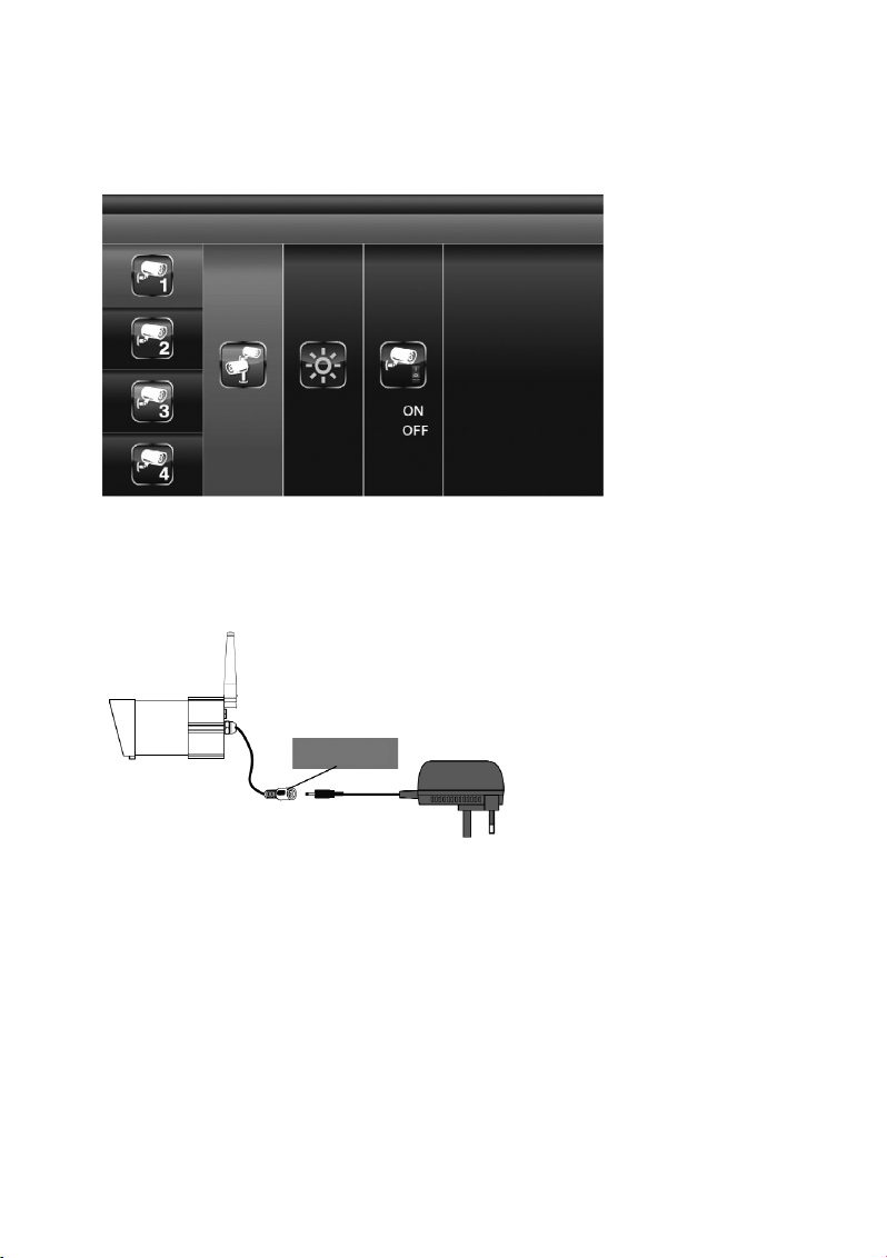
64
"PAIRING" (Connecting a Surveillance Camera to the Indoor Unit)
If you want to connect other surveillance cameras in addition to the included one to the indoor unit of this
set ("Pairing"), ensure that each of these devices uses another channel than the surveillance camera(s)
already installed. The indoor unit can be used to operate up to four surveillance cameras.
When "PAIRING" is highlighted, push the "MENU" button (6) once to start pairing between the surveillance camera and the indoor unit.
Then push the pairing button at the end of the camera cable. It is on the connection piece to the plug-in
mains adapter.
The pair LED on the surveillance camera will flash once. Continuous flashing of the LED signals that
data transmission is underway.
The system confirms successful connection between surveillance camera and indoor unit by displaying
the word "PAIRED" on the indoor unit.
If connection between surveillance camera and indoor unit fails, the system shows the screen message
"PAIRING FAIL".
Push the button "ESC" (8) to leave the menu.
Pairing key
Page 65

65
"BRIGHTNESS" (Setting the Surveillance Camera Brightness)
Use the arrow (5) to select the function "BRIGHTNESS". Use the arrows (3) and (7) to
adjust the brightness for display of the camera picture.
Push the button "ESC" (8) to leave the menu.
"ACTIVATE OR DEACTIVATE" (Activating/Deactivating a Surveillance Camera)
Use the arrow (5) to select the menu item "ACTIVATE OR DEACTIVATE" to activate or deactivate the
selected surveillance camera. Use the arrows (3) and (7) to activate ("ON") or deactivate ("OFF")
the selected surveillance camera.
Push the button "ESC" (8) to leave the menu.
☞
Activation and deactivation of a surveillance camera is only possible when it is correctly
registered at the indoor unit. For more information on this, see the chapter "PAIRING".
Page 66
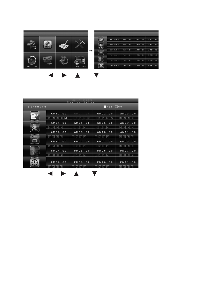
66
c) "RECORDER SETUP" (Video Recorder Setup)
Use the arrows (4), (5), (3) and (7) to select the function "REC" and push the "MENU"
button (6) again to get to the submenu of the "RECORDER SETUP".
"RECORD SCHEDULE" (Recording Schedule)
Use the arrows (4), (5), (3) and (7) to select the time for starting a video recording. Push
the "MENU" (6) button to change the settings of the recording schedule.
You may choose between three different recording versions. Select the time for start of the video recording first and then push the "MENU" button (6) once or repeatedly to switch through the recording options:
M: "MOTION" (recording is only started when the system registers movement)
S: "SCHEDULE" (planned continuous recording)
C: "MANUAL" (manual recording)
In all three modes the system will record videos from all four surveillance camera channels at once. For
the first one of the four channels, audio can be recorded as well. An audio channel is available in QUAD
mode (by default, channel 1 or the next available channel with a connected and coupled surveillance
camera (pairing) is pre-set), in single channel full-screen mode or "MOTION" mode (motion detection).
In "MOTION" mode, sound recording is activated automatically once the system registers a moving
object.
Page 67

67
To start a recording in "MANUAL" mode, push the button "REC/DEL" (9) once.
The record can be sopped again no earlier than 30 seconds after starting the recording. To stop a recor-
ding, push the button "REC/DEL" (9) once.
Ꮨ
Always switch off the system before removing the memory card from the indoor unit!
In "SCHEDULE"-mode, the system will automatically continue 60 seconds after the recording was
manually terminated.
In "MOTION" mode, the motion detection will start again after 60 seconds if the recording was manually
terminated.
The recording must be stopped before you can call the main menu. If no other input is made for 2 minutes,
the system automatically switches back to "QUAD" mode.
"MOTION DETECTION SENSITIVITY" (Setting the Sensitivity for Motion Detection)
Use the arrows (4), (5), (3) and (7) to select the function "RECORDER SETUP" and
push the "MENU" button (5).
Use the arrows (3) and (7) to select the menu item "MOTION DETEC-TION SENSITIVITY" to set
the sensitivity for motion detection at the left edge.
Use the arrows (4) and (5) to select the desired surveillance camera (1 - 4) in the right fields.
Use the arrows (3) and (7) to adjust sensitivity: "OFF" / "LV1" / "LV2" / "LV3" ("LV3" is the most
sensitive setting).
Push the "ESC" button (8) to save the settings and leave the menu.
Page 68

68
"FORMAT STORAGE" (Format Memory Card)
Use the arrows (4), (5), (3) and (7) to select the function "RECORDER SETUP" in the
main menu and push the "MENU" button (6).
Use the arrows (3) and (7) to select the menu item "MENU: START FORMAT" to format the
memory card at the left edge.
Push the "MENU" button (6) again to confirm your input and commence formatting of the memory card.
Push the button "ESC" (8) to leave the menu.
"SETUP MASKING AREA" (Setting "Masking" Area)
Use the arrows (4), (5), (3) and (7) to select the function "RECORDER SETUP" in the
main menu and push the "MENU" button (6).
Use the arrows (3) and (7) to select the menu item "SETUP MASKING AREA" at the left edge to
determine the masking area.
Use the arrows (4), (5) to select the desired surveillance camera and push the "MENU" button
(6) to confirm your selection.
Use the arrows (4), (5), (3) and (7) to select the areas of the grid in which your motion
detection is not to be effective. Push the "MENU"-button (6) to mask a segment in the grid or to remove
masking.
☞
Motions in the masked areas are ignored by the system and will not trigger recording in
"MOTION" mode.
Push the "ESC" button (8) to save the settings and leave the menu.
Page 69

69
"RECORD TIME" (Setting the Recording Duration)
Use the arrows (4), (5), (3) and (7) to select the function "RECORDER SETUP" and
push the "MENU" button (6).
Use the arrows (3) and (7) to select the menu item "RECORD TIMEAREA" at the left edge to
determine duration of a video recording.
Use the arrows (4), (5) select the desired recording duration per file saved: "2 MINUTES PER
FILE" / "5 MINUTES PER FILE" / "10 MINUTES PER FILE". Then push the "MENU" button (6) to confirm
your selection.
Push the "ESC" button (8) to save the settings and leave the menu.
Page 70
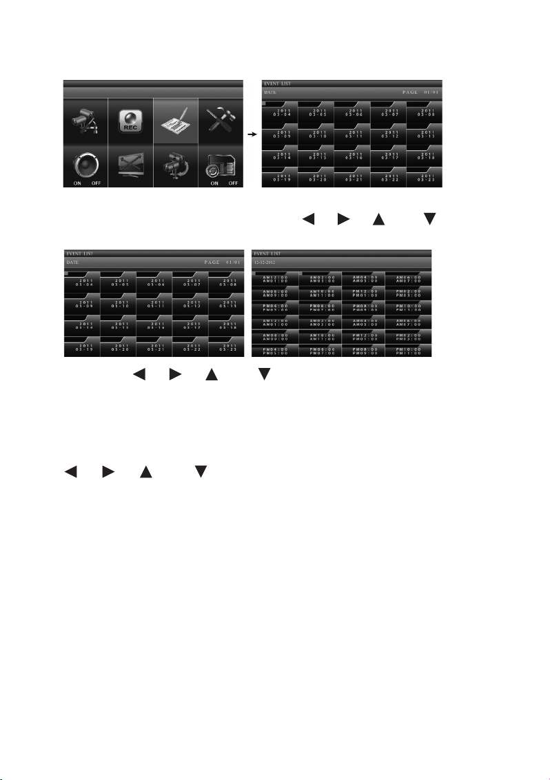
70
d) "EVENT LIST"
When calling the main menu with the "MENU" button (5), the menu item "EVENT LIST" is already automatically selected. If this is not the case, use the arrows (4), (5), (3) and (7) to select the
menu item "EVENT LIST" and push the "MENU" button (5) again to get to the event list.
Use the arrows (4), (5), (3) and (7) to select the folder with the desired recording date
for which you want to view saved video recordings from the list "DATE". The date is presented as follows
in the folders:
[year]
[month - day]
Push the "MENU" button (6) to confirm your selection and open the selected folder. Now use the arrows
(4), (5), (3) and (7) to select the folder with the desired hour from the displayed list
(every subfolder represents one hour) and push the "MENU" button (6) for confirmation.
Each folder with a video recording shows information on record start and end and on the selected sur-
veillance camera channels and the recording mode.
Page 71

71
1. Start and end of the recording
Start: 10:33 pm (22:33 hours)
End: 10:43 pm (22:43 hours)
Depending on the value selected in the menu "RECORD TIME", a single file contains a video recording
of 2, 5 or 10 minutes.
2. Recording mode
The recorded video of surveillance camera channel 1 was recorded in the "SCHEDULE" mode (S) (planned,
continuous recording).
The recorded video of surveillance camera channel 1 was recorded in the "MOTION" mode (M) (motion
detection).
The recorded videos of channels 1, 2, 3 and 4 were recorded in MANUAL mode (X).
Use the arrows (4), (5), (3) and (7) and then push the "MENU" button (5).
Page 72

72
= playback of all surveillance camera channels
If you want to view the recording of a single surveillance camera channel, push the "MENU" button (5)
for PAUSE briefly after starting playback. Use the arrows (4), (5) now to select the desired surveillance camera channel and confirm the selection with the "MENU" button (6).
The channel display at the lower left screen edge tells you which channel is currently active:
= Channel 1 in full-screen display
= Channel 2 in full-screen display
= Channel 3 in full-screen display
= Channel 4 in full-screen display
The included CD-ROM contains the software Sec24 Media Player, with which you can play
back the recorded files on your Windows-PC.
☞
Page 73
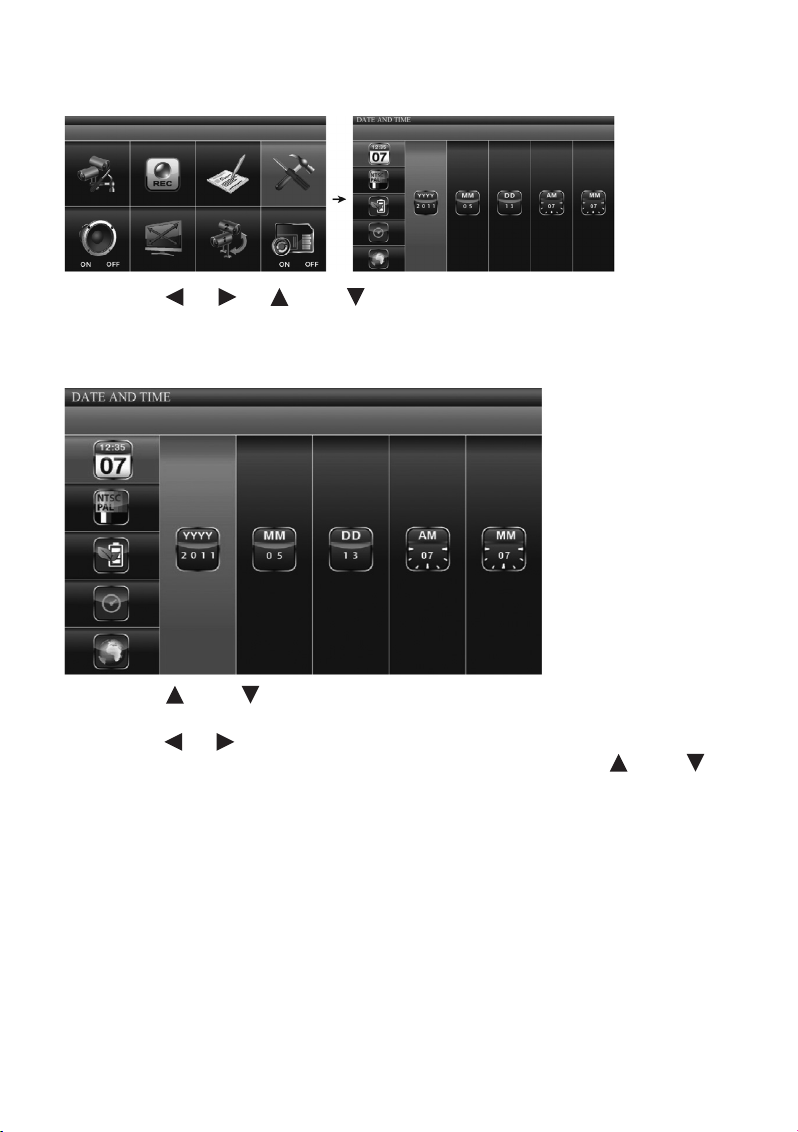
73
e) "SYSTEM SETUP"
Use the arrows (4), (5), (3) and (7) to select the function "SYSTEM SETUP" and push
the "MENU" button (6) again to get to the submenu "DATE AND TIME".
"DATE AND TIME"
Use the arrows (3) and (7) to select "DATE AND TIME" on the left edge of the screen and push
the "MENU" button (6).
Use the arrows (4), (5) to select the settings for "YYYY" (year), "MM" (month), "DD" (day), "PM"
or "AM" (time/hour) and "MM" (time/minute) and set the correct values with the arrows (3) and
(7). When the value is set correctly, confirm input with the "MENU" button (6).
Push the "ESC" button (8) to save the settings and leave the menu.
Page 74

74
"TV OUTPUT" (TV-Output: NTSC/PAL)
☞
Use the included A/V cable to connect the system to a screen or TV if required. Observe the
notes in section 7e ("Installation/Cable Connections").
Push the "MENU" button (6) and select the menu item "SYSTEM SETUP" (upper right) in the main menu
with the arrows (4), (5), (3) and (7). Push the "MENU" button (6) again to confirm your
selection.
Use the arrows (3) and (7) to select "TV OUTPUT" in the selection menu at the left edge of the
screen and push the "MENU" button (6).
Use the arrows (4), (5) to select NTSC or PAL, depending on system, and push the "MENU" button (6) to confirm your input.
Push the "ESC" button (8) to save the settings and leave the menu.
☞
Switching the TV system may change the screen display.
Page 75

75
"POWER SAVING" (Power-Saving Mode)
Push the "MENU" button (5) and select the menu item "SYSTEM SETUP" (upper right) in the main menu
with the arrows (4), (5), (3) and (7). Push the "MENU" button (6) again to confirm your
selection.
Use the arrows (3) and (7) to select "POWER SAVING" in the selection menu at the left edge of
the screen and push the "MENU" button (6).
Use the arrows (4), (5) to select one of the following options:
The screen is deactivated if no input was made for 5 minutes.
Page 76
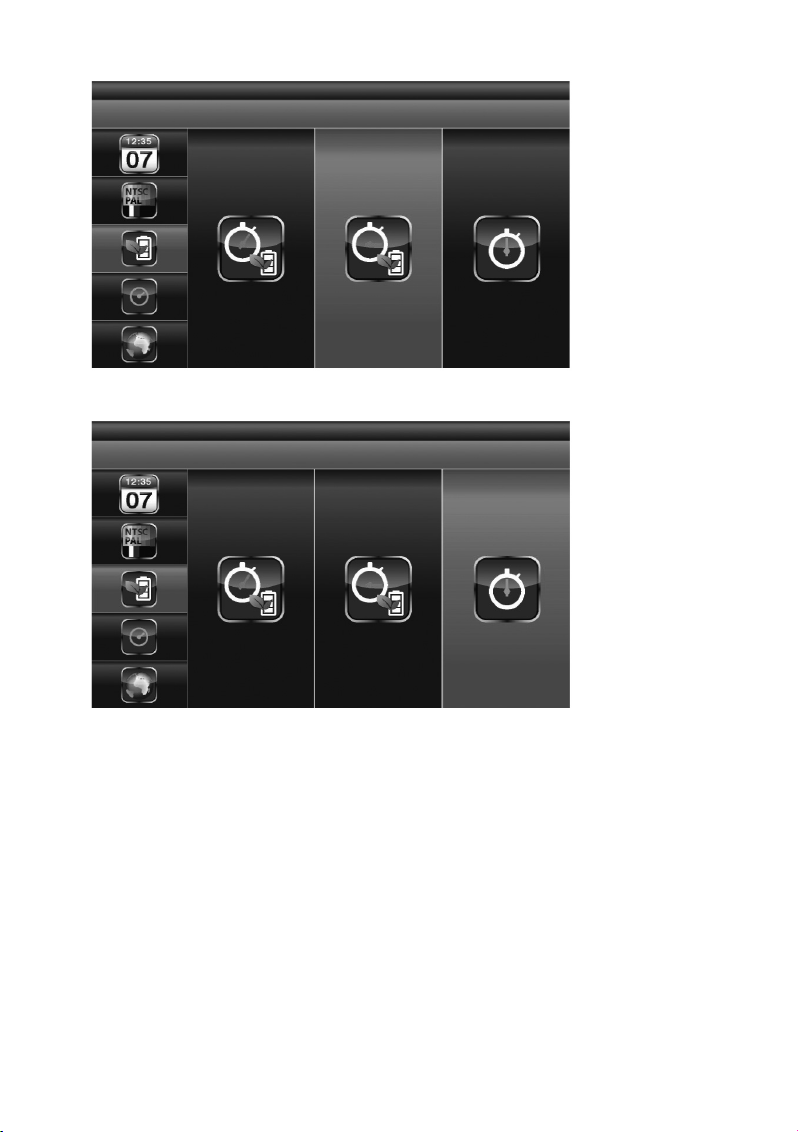
76
The screen is deactivated if no input was made for 10 minutes.
The screen remains active at all times.
Press the MENU (6) button to confirm your input.
Push the "ESC" button (8) to save the settings and leave the menu.
Page 77

77
"MULTI CHANNELS IDLE DISPLAY" (screen display in phases in which no video recording or
user input takes place)
this option specifies the operating mode for each surveillance camera channel for the case that you do
not make any input for an extended period and that no video recording is currently active.
Push the "MENU" button (6) and select the menu item "SYSTEM SETUP" (upper right) in the main menu
with the arrows (4), (5), (3) and (7). Push the "MENU" button (5) again to confirm your
selection.
Use the arrows (3) and (7) to select "MULTI CHANNELS IDLE DISPLAY " in the selection menu
at the left edge of the screen and push the "MENU" button (6).
Use the arrows (4), (5) to select one of the following options:
QUAD mode: The fourfold divided screen shows pictures from all for surveillance camera channels at
once.
Page 78

78
The pictures of the connected surveillance cameras are displayed for 5 seconds each alternatingly in
"SCAN" mode.
The pictures of the connected surveillance cameras are displayed for 10 seconds each alternatingly in
"SCAN" mode.
Page 79

79
The pictures of the connected surveillance cameras are displayed for 15 seconds each alternatingly in
"SCAN" mode.
Confirm your input by pushing the "MENU" button (6).
Push the "ESC" button (8) to save the settings and leave the menu.
☞
Activation and deactivation of cameras in the "CAMERA SETUP" (surveillance camera
setup, see chapter 10b) determines the channels for which pictures are shown on the
screen in idle mode.
An audio channel is available in QUAD mode (by default, channel 1 or the next available
channel with a connected and coupled surveillance camera (pairing) is pre-set), in single
channel full-screen mode or "MOTION" mode (motion detection).
The audio channel remains connected until the channel is switched.
If 5/10/15 second intervals are set for "MULTI CHANNELS IDLE DISPLAY", use the arrows
(4), (5), (3) and (7) to select the option "SCAN ACTIVATED CAMERAS" in
the main menu to activate this display mode.
Page 80

80
"DEFAULT" (Restore Standard Settings)
Push the "MENU" button (6) and select the menu item "SYSTEM SETUP" (upper right) in the main menu
with the arrows (4), (5), (3) and (7). Push the "MENU" button (6) again to confirm your
selection.
Use the arrows (3) and (7) to select "DEFAULT" in the selection menu at the left edge of the
screen and push the "MENU" button (6).
Use the arrow (5) to select the language settings for system recovery, push the "MENU" button (6)
and start recovery of the works standard settings.
Page 81

81
f) "ALARM BUZZER" (Acoustic Alarm)
Push the "MENU" button (6) and select the menu item "ALARM BUZZER" (lower left) in the main menu
with the arrows (4), (5), (3) and (7).
When the surveillance camera registers a moving object, the monitor will emit an alarm by default. Pushing
the "MENU" button (5) activates ("ON") and deactivates ("OFF") the alarm.
Page 82

82
g) PAN TILT ZOOM" (pan, tilt or zoom the picture section displayed on
the screen)
Pus the "MENU" button (5) and use the arrows (4), (5), (3) and (7) in the main menu to
select the function "PAN TILT ZOOM" and push the "MENU" button (6) again to get to the submenu "PAN
TILT ZOOM".
☞
The surveillance camera as such cannot be panned. The function "PAN TILT ZOOM" only
changes the picture section displayed on the indoor unit.
Push the "MENU" button (6) again in "PAN TILT ZOOM" mode to activate the second zoom stage for the
picture of the selected monitoring camera. Push the arrows (4), (5), (3) and (7) repeatedly to then adjust the displayed section to the left, right, up or down in small steps.
Push the MENU (6) button again to zoom out again.
In zoom level 1, use the arrows (3) and (7) to switch between the individual surveillance came-
ra channels.
Push the "ESC" button (8) to terminate the "ZOOM" mode.
Page 83

83
h) "SCAN ACTIVATED CAMERAS" ("SCAN"-Mode)
Pus the "MENU" button (6) and use the arrows (4), (5), (3) and (7) in the main menu to
select the function "SCAN ACTIVATED CAMERAS" and push the "MENU" button (5) again to activate
"SCAN" mode for the activated surveillance cameras. In "SCAN" mode, the system switches through the
current pictures of the activated surveillance cameras at regular intervals on the indoor unit's display.
☞
The "ON"/"OFF"-settings with which you have activated or deactivated the connected surveillance cameras in the main menu's "CAMERA SETUP" determine the pictures to be displayed by the individual surveillance cameras when the screen is idling ("SCAN ACTIVATED
CAMERAS").
Chapter "MULTI CHANNELS IDLE DISPLAY" shows how to set the time intervals for the
screen display in "SCAN" mode.
During video recording, the system automatically activates "QUAD" mode.
Page 84

84
i) "MEMORY CARD OVERWRITE" (Overwrite Memory Card)
Activating the function "MEMORY CARD OVERWRITE" permits overwriting the oldest files with the
latest recordings if the memory card has no memory left for new recordings.
Use the arrows (4), (5), (3) and (7) to select the function "MEMORY CARD OVERWRITE"
in the main menu and push the "MENU" button (6) again to activate ("ON") or deactivate ("OFF) the data on
the memory card.
With the memory card inserted, the remaining memory space is displayed, e.g. "1.89 GB space
available on memory card".
If no memory card is inserted, if it is overwrite protected or damaged, the system will show
an ERROR message instead.
If the memory card is full, the system outputs the message "MEMORY FULL PLEASE FORMAT" if "MEMORY CARD OVERWRITE" is not activated in the main menu ("OFF").
☞
Page 85

85
11. Playback Software: Sec24 Media Player
The Sec24 Media Player has been developed specifically for playing back the recordings of the video
surveillance system with 2.4 GHz digital radio colour camera and radio receiver on a PC. Other users
cannot play your recordings without the Sec24 Media Player– this is a cautionary method to protect
your data and privacy.
a) The Operating Elements of the Sec24 Media Player
1. Surveillance camera channel 1 playback area
2. Surveillance camera channel 2 playback area
3. Surveillance camera channel 3 playback area
4. Surveillance camera channel 4 playback area
5. Playback progress bar
6. Playback
7. Pause
8. Stop
9. Rewind
10. Fast forward
11. "Load": Load file with video recordings
12. Replay last file
13. "Channel": Activate/deactivate camera channels
Page 86

86
b) Installation of the Sec24 Media Player (MS Windows)
Insert the CD-ROM included in the delivery of this 2.4 GHz digital radio DVR monitor set in the CD-ROM
drive of your PC.
Double-click the icon "Computer" on your desktop and then the icon of your CD-ROM drive to open the
corresponding folder. You will find an installation file there that is called "Sec24 Media Player". (The file
name may also include the current version number of the programme.)
Follow the instructions on the screen for installation.
A. Double-click the file icon to start installation.
1. If you have the operating system Windows 7 on your computer, right-click the icon of the
file called "Sec24 Media Player" and left-click the menu item "Execute as administrator"
to start installation of the Sec24 Media Player.
2. If you start the installation without administrator rights, you may be shown the following error message:
Page 87

87
If the installation starts successfully, the following message is displayed:
B. Click "Next" or "Weiter" to continue installation.
Page 88
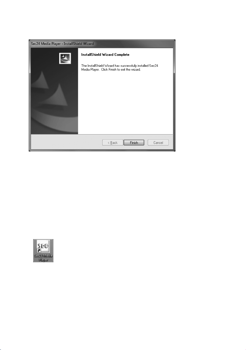
88
C. Once installation has been completed, the following message appears on the screen. Click "Finish" or
"Beenden" to close the window.
c) Play Back File(s) with Video Recordings on the PC
1. Take the MicroSD memory card from the slot of the indoor unit of your video surveillance system and
insert the memory card in the corresponding card reader of your PC.
If your PC has no MicroSD slot, insert the MicroSD memory card in the concluded SD
adapter and then push it into the corresponding card reader of your PC.
Your PC recognises the memory card automatically and assigns it a drive letter (e.g. "E") and shows
it as removable medium in the drive list in Windows.
2. Double-click the Sec24-icon on your Windows Desktop with the left mouse button to start the MediaPlayer software.
Page 89
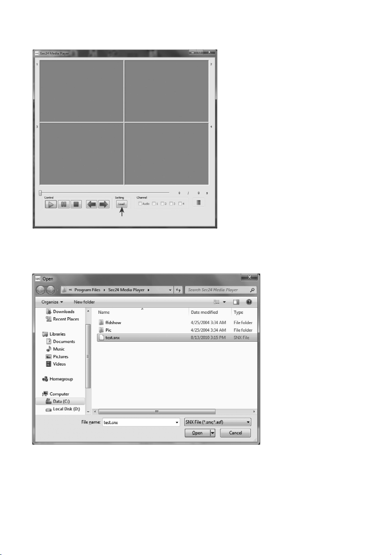
89
3. Then click "Load" to load video recordings.
4. Select the memory card (e.g. removable medium E:) from the displayed drive list and double-click the
icon to display the saved video files (extension".SNX"). Select the desired .SNX-file with a mouse-click
and click "Open" or "Öffnen" to start playback.
Page 90

90
d) Activate and Deactivate Channels
All four surveillance camera channels and the audio channel are active by default for playback. On
demand, individual channels can be deactivated manually:
Remove the checkmark from the corresponding box by left-clicking:
• Audio
• 1: Video channel 1
• 2: Video channel 2
• 3. Video channel 3
• 4. Video channel 4
Page 91

91
12. Declaration of Conformity (DOC)
We, Conrad Electronic, Klaus-Conrad-Straße 1, D-92240 Hirschau, hereby declare that this product
complies with the fundamental requirements and the other relevant regulations of the directive
1999/5/EC.
☞
The compliance statement for this product is available at www.conrad.com.
13. Maintenance and Cleaning
The product does not require any maintenance, never take it apart. Cleaning with a dry, clean and soft
cloth is sufficient; disconnect the product from the power source before cleaning it, pull the plug-in mains
adapter from the mains socket. Clean the lens very carefully to avoid scratches. Do not use aggressive
detergents as these will cause discoloration of the casing. Do not push too hard on the display of the
indoor unit. This may cause scratches and damage the display.
14. Troubleshooting
Problem Solution
The surveillance camera The plug-in mains adapter of the indoor unit or the surveillance
does not show any picture. camera(s) is not connected to the power supply. The surveillance
camera is installed outside of radio reach of the indoor unit. Reduce
the distance between surveillance camera and indoor unit.
Poor image quality. Clean the lens of the surveillance camera.
Only a white picture is shown The infrared LEDs of the surveillance camera show otherwise
at night. invisible light that is reflected from surfaces like glass. Place the
surveillance camera in front of the window or at another position.
Page 92

92
15. Disposal
a) Product
Electronic devices are recyclable waste and must not be disposed of in the household waste! Dispose of the product according to the applicable statutory provisions at the end of its
service life.
Remove any inserted battery and dispose of them separately from the product.
b) Batteries and Rechargeable Batteries
You as the end user are required by law (Battery Ordinance) to return all used batteries/rechargeable
batteries. Disposing of them in the household waste is prohibited!
Batteries/rechargeable batteries that contain any hazardous substances are labelled with
the adjacent icon to indicate that disposal in domestic waste is forbidden.
The descriptions for the respective heavy metal are: Cd=cadmium, Hg=mercury, Pb=lead
(the names are indicated on the battery/rechargeable battery e.g. below the rubbish bin
symbol shown to the left).
You may return used batteries/rechargeable batteries free of charge at the official collection points of
your community, in our stores, or wherever batteries/rechargeable batteries are sold! You thus fulfil your
statutory obligations and contribute to the protection of the environment.
16. Technical Data
a) Surveillance Camera
Max. number of channels . . . . . . . . . . . . . . . . . 1
Range of wireless data transmission. . . . . . . . . 150 m in the free field
Camera resolution. . . . . . . . . . . . . . . . . . . . . . . 640 x 480
Transmission frequency . . . . . . . . . . . . . . . . . . 2.4 GHz
Operating temperature . . . . . . . . . . . . . . . . . . . -10 °C ~ +50 °C
Operating voltage . . . . . . . . . . . . . . . . . . . . . . . 5 V/DC, 1 A
Current consumption. . . . . . . . . . . . . . . . . . . . . IR OFF: 165±20 mA
IR ON: 465±20 mA
Night-view range (IR-LEDs). . . . . . . . . . . . . . . . 5 - 8 m
Protection type . . . . . . . . . . . . . . . . . . . . . . . . . IP66 (suitable for the outdoor area)
Dimensions . . . . . . . . . . . . . . . . . . . . . . . . . . . . 124 x 61 x 67 mm
Page 93

93
b) DVR/Monitor Indoor Unit
Max. number of channels . . . . . . . . . . . . . . . . . 4
Range of wireless data transmission. . . . . . . . . 150 m in the free field
Screen resolution . . . . . . . . . . . . . . . . . . . . . . . 320 x 240
Recording time . . . . . . . . . . . . . . . . . . . . . . . . . 2 Min., 5 Min., 10 Min.
Minimum recording time . . . . . . . . . . . . . . . . . . 30 sec.
File format recordings . . . . . . . . . . . . . . . . . . . . MP4, file format .SNX
Operating temperature . . . . . . . . . . . . . . . . . . . 0 °C to +40 °C
Operating voltage . . . . . . . . . . . . . . . . . . . . . . . 5 V/DC, 1 A
Current consumption. . . . . . . . . . . . . . . . . . . . . 220±20 mA
Integrated card reader. . . . . . . . . . . . . . . . . . . . microSD, microSDHC, max. 32 GB
Integrated rechargeable battery . . . . . . . . . . . . N/A
Dimensions . . . . . . . . . . . . . . . . . . . . . . . . . . . . 113 x 113 x 26 mm
c) Mains Adapter
Power supply. . . . . . . . . . . . . . . . . . . . . . . . . . . 100 - 240 V/AC, 50/60 Hz
Output . . . . . . . . . . . . . . . . . . . . . . . . . . . . . . . . 5 V/DC, 1 A
d) Recording Capacity of Memory Cards (max. 32 GB)
☞
The recording capacities indicated depend on the compressing capacity of the picture data
and can therefore deviate in practice.
1 GB microSD . . . . . . . . . . . . . . . . . . . . . . . . . . 60 min
2 GB microSD . . . . . . . . . . . . . . . . . . . . . . . . . . 110 min
8 GB microSDHC . . . . . . . . . . . . . . . . . . . . . . . 400 min
16 GB microSDHC . . . . . . . . . . . . . . . . . . . . . . 950 min
32 GB microSDHC . . . . . . . . . . . . . . . . . . . . . . 1,880 min
Page 94

94
Table des matières
Page
1. Introduction. . . . . . . . . . . . . . . . . . . . . . . . . . . . . . . . . . . . . . . . . . . . . . . . . . . . . . . . . . . . . . . . . . . 96
2. Utilisation conforme . . . . . . . . . . . . . . . . . . . . . . . . . . . . . . . . . . . . . . . . . . . . . . . . . . . . . . . . . . . . 97
3. Étendue de la livraison . . . . . . . . . . . . . . . . . . . . . . . . . . . . . . . . . . . . . . . . . . . . . . . . . . . . . . . . . . 97
4. Explication des symboles . . . . . . . . . . . . . . . . . . . . . . . . . . . . . . . . . . . . . . . . . . . . . . . . . . . . . . . . 98
5. Consignes de sécurité . . . . . . . . . . . . . . . . . . . . . . . . . . . . . . . . . . . . . . . . . . . . . . . . . . . . . . . . . . 98
6. Disposition optimale des caméras, de l’unité intérieure et du moniteur . . . . . . . . . . . . . . . . . . . . . 99
7. Installation. . . . . . . . . . . . . . . . . . . . . . . . . . . . . . . . . . . . . . . . . . . . . . . . . . . . . . . . . . . . . . . . . . . 100
a) Remarques . . . . . . . . . . . . . . . . . . . . . . . . . . . . . . . . . . . . . . . . . . . . . . . . . . . . . . . . . . . . . . . 100
b) Positionnement de la caméra de surveillance. . . . . . . . . . . . . . . . . . . . . . . . . . . . . . . . . . . . . 100
c) Fonction de vision nocturne . . . . . . . . . . . . . . . . . . . . . . . . . . . . . . . . . . . . . . . . . . . . . . . . . . 100
d) Installation de la (ou des) caméra(s) de surveillance . . . . . . . . . . . . . . . . . . . . . . . . . . . . . . . 100
e) Raccordements . . . . . . . . . . . . . . . . . . . . . . . . . . . . . . . . . . . . . . . . . . . . . . . . . . . . . . . . . . . . 102
f) Mise en service du système . . . . . . . . . . . . . . . . . . . . . . . . . . . . . . . . . . . . . . . . . . . . . . . . . . 103
g) Réglage du canal de la caméra de surveillance (en option) . . . . . . . . . . . . . . . . . . . . . . . . . . 103
8. Éléments de commande de l’unité intérieure (DVR / récepteur) et de
la télécommande à infrarouge . . . . . . . . . . . . . . . . . . . . . . . . . . . . . . . . . . . . . . . . . . . . . . . . . . . 104
9. Fonctions système . . . . . . . . . . . . . . . . . . . . . . . . . . . . . . . . . . . . . . . . . . . . . . . . . . . . . . . . . . . . 105
a) La signification des symboles sur l’écran . . . . . . . . . . . . . . . . . . . . . . . . . . . . . . . . . . . . . . . . 105
b) Structure du menu de l’unité intérieure . . . . . . . . . . . . . . . . . . . . . . . . . . . . . . . . . . . . . . . . . . 107
10. Utilisation du système. . . . . . . . . . . . . . . . . . . . . . . . . . . . . . . . . . . . . . . . . . . . . . . . . . . . . . . . . . 108
a) Menu du système . . . . . . . . . . . . . . . . . . . . . . . . . . . . . . . . . . . . . . . . . . . . . . . . . . . . . . . . . . 108
b) CAMERA SETUP » (setup de la caméra de surveillance). . . . . . . . . . . . . . . . . . . . . . . . . . . 109
« PAIRING » (connexion d’une caméra de surveillance à l’unité intérieure). . . . . . . . . . . . . 110
« BRIGHTNESS » (réglage de la luminosité de la caméra de surveillance). . . . . . . . . . . . . 111
« ACTIVATE OR DEACTIVATE » (activation / désactivation de la caméra de surveillance) 111
c) « RECORDER SETUP » (setup du magnétoscope). . . . . . . . . . . . . . . . . . . . . . . . . . . . . . . 112
« RECORD SCHEDULE » (calendrier des enregistrements) . . . . . . . . . . . . . . . . . . . . . . . . 112
« MOTION DETECTION SENSITIVITY » (réglage de la sensibilité pour
la détection des mouvements). . . . . . . . . . . . . . . . . . . . . . . . . . . . . . . . . . . . . . . . . . . . . . . . . 113
« FORMAT STORAGE » (formatage de la carte mémoire). . . . . . . . . . . . . . . . . . . . . . . . . . 114
« SETUP MASKING AREA » (définition de la plage des « Camouflages ») . . . . . . . . . . . 114
« RECORD TIME » (réglage de la durée d’enregistrement) . . . . . . . . . . . . . . . . . . . . . . . . . 115
d) « EVENT LIST » (liste des événements). . . . . . . . . . . . . . . . . . . . . . . . . . . . . . . . . . . . . . . . 116
Page 95

95
Page
e) « SYSTEM SETUP » (setup du système). . . . . . . . . . . . . . . . . . . . . . . . . . . . . . . . . . . . . . . 119
« DATE AND TIME » (date et heure) . . . . . . . . . . . . . . . . . . . . . . . . . . . . . . . . . . . . . . . . . . 119
« TV OUTPUT » (sortie TV : NTSC/PAL) . . . . . . . . . . . . . . . . . . . . . . . . . . . . . . . . . . . . . . 120
« POWER SAVING » (mode d’économie d’énergie). . . . . . . . . . . . . . . . . . . . . . . . . . . . . . . 121
« MULTI CHANNELS IDLE DISPLAY » . . . . . . . . . . . . . . . . . . . . . . . . . . . . . . . . . . . . . . . . 123
« DEFAULT » (restauration des réglages par défaut). . . . . . . . . . . . . . . . . . . . . . . . . . . . . . 126
f) « ALARM BUZZER » (alarme sonore) . . . . . . . . . . . . . . . . . . . . . . . . . . . . . . . . . . . . . . . . . 127
g) « PAN TILT ZOOM » . . . . . . . . . . . . . . . . . . . . . . . . . . . . . . . . . . . . . . . . . . . . . . . . . . . . . . . 128
h) « SCAN ACTIVATED CAMERAS » (mode « SCAN »). . . . . . . . . . . . . . . . . . . . . . . . . . . . 129
i) « MEMORY CARD OVERWRITE » (écrasement de la carte mémoire). . . . . . . . . . . . . . . . 130
11. Logiciel de lecture : lecteur multimédia Sec24 . . . . . . . . . . . . . . . . . . . . . . . . . . . . . . . . . . . . . . 131
a) Les éléments de commande du lecteur multimédia Sec24. . . . . . . . . . . . . . . . . . . . . . . . . . . 131
b) Installation du lecteur multimédia Sec24 (MS Windows) . . . . . . . . . . . . . . . . . . . . . . . . . . . . 132
c) Lecture des fichiers d’enregistrement vidéo sur l’ordinateur . . . . . . . . . . . . . . . . . . . . . . . . . . 134
d) Activation et désactivation des canaux . . . . . . . . . . . . . . . . . . . . . . . . . . . . . . . . . . . . . . . . . . 136
12. Déclaration de conformité (DOC) . . . . . . . . . . . . . . . . . . . . . . . . . . . . . . . . . . . . . . . . . . . . . . . . . 137
13. Entretien et nettoyage. . . . . . . . . . . . . . . . . . . . . . . . . . . . . . . . . . . . . . . . . . . . . . . . . . . . . . . . . . 137
14. Dépannage . . . . . . . . . . . . . . . . . . . . . . . . . . . . . . . . . . . . . . . . . . . . . . . . . . . . . . . . . . . . . . . . . . 137
15. Élimination . . . . . . . . . . . . . . . . . . . . . . . . . . . . . . . . . . . . . . . . . . . . . . . . . . . . . . . . . . . . . . . . . . 138
a) Produit. . . . . . . . . . . . . . . . . . . . . . . . . . . . . . . . . . . . . . . . . . . . . . . . . . . . . . . . . . . . . . . . . . . 138
b) Piles et batteries . . . . . . . . . . . . . . . . . . . . . . . . . . . . . . . . . . . . . . . . . . . . . . . . . . . . . . . . . . . 138
16. Caractéristiques techniques . . . . . . . . . . . . . . . . . . . . . . . . . . . . . . . . . . . . . . . . . . . . . . . . . . . . . 138
a) Caméra de surveillance. . . . . . . . . . . . . . . . . . . . . . . . . . . . . . . . . . . . . . . . . . . . . . . . . . . . . . 138
b) Unité intérieure DVR . . . . . . . . . . . . . . . . . . . . . . . . . . . . . . . . . . . . . . . . . . . . . . . . . . . . . . . . 139
c) Bloc d’alimentation . . . . . . . . . . . . . . . . . . . . . . . . . . . . . . . . . . . . . . . . . . . . . . . . . . . . . . . . . 139
d) Durée d’enregistrement des cartes mémoire (max. 32 Go) . . . . . . . . . . . . . . . . . . . . . . . . . . 139
Page 96

96
1. Introduction
Chère cliente, cher client,
Nous vous remercions pour l’achat du présent produit. Ce produit est conforme aux exigences légales
des directives européennes et nationales en vigueur. Afin de maintenir l’appareil en bon état et d’en
assurer un fonctionnement sans danger, l’utilisateur doit impérativement respecter le présent mode
d’emploi !
Le présent mode d’emploi fait partie intégrante du produit. Il contient des remarques
importantes pour la mise en service et la manipulation du produit. Tenez compte de
ces remarques, même en cas de cession de ce produit à un tiers. Conservez le présent mode d’emploi afin de pouvoir le consulter à tout moment !
Tous les noms d’entreprises et appellations de produits contenus dans ce mode d’emploi sont des marques déposées des propriétaires respectifs. Tous droits réservés.
En cas de questions ou de problèmes, adressez-vous à notre service d’assistance technique:
France: Tél. 0892 897 777
Fax 0892 896 002
du lundi au vendredi de 8h00 à 18h00
le samedi de 8h00 à 12h00
Suisse: Tél 0848 / 80 12 88
Fax 0848 / 80 12 89
e-mail:support@conrad.ch
du lundi à vendredi de 8h00 à 12h00, 13h00 à 1
7h00
Page 97

97
2. Utilisation conforme
Le système de surveillance vidéo avec détection des mouvements et fonction de vision diurne / nocturne a été conçu pour la surveillance, par ex. des entrées, entrées de cour, etc. La caméra de surveillance retransmet le signal vidéo et le signal audio sans fil à l’unité intérieure (DVR). Les signaux peuvent
y être enregistrés sur une carte microSD ou microSDHC.
L’alimentation électrique de la caméra de surveillance et de l’unité intérieure est respectivement assurée par
le bloc d’alimentation fourni.
L’unité intérieure et les deux blocs d’alimentation conviennent uniquement pour une utilisation en intérieur, dans les locaux fermés et non humides. La caméra de surveillance peut être montée et utilisée à
l’extérieur (IP66).
En cas d’observation de personnes étrangères sans qu’elles ne le sachent et sans leur consentement,
vous pouvez faire l’objet de poursuites en justice. Observez les dispositions et consignes en vigueur
dans le pays d’utilisation de la caméra de surveillance.
Lisez intégralement et attentivement le présent mode d’emploi. Il contient des informations importantes
relatives au montage, à la mise en service et au fonctionnement de l’appareil. Observez toutes les consignes de sécurité !
Toute utilisation autre que celle décrite précédemment peut provoquer l’endommagement du produit.
Une telle utilisation s’accompagne également de dangers tels que courts-circuits, incendies, électrocutions, etc. Il est interdit de modifier ou transformer l’intégralité du produit !
3. Étendue de la livraison
• Unité intérieure (DVR)
• Télécommande à infrarouge (fournie avec pile du type CR2025)
• Caméra de surveillance
• Antenne pour la caméra de surveillance
• Support de montage pour la caméra de surveillance
• 2 blocs d’alimentation
• Matériel de montage
• Câble AV pour la sortie moniteur / TV
• Cédérom avec logiciel de l’ordinateur pour la lecture vidéo (Windows)
• Mode d’emploi
Page 98

98
4. Explication des symboles
Ꮨ
Le symbole de l’éclair dans le triangle signale un danger pour votre santé, par ex. par
électrocution.
Le symbole avec le point d’exclamation placé dans u
n triangle signale les informations
importantes du présent mode d’emploi qui doivent impérativement être respectées.
☞
Le symbole de la « main » précède les recommandations et indications d’utilisation particulières.
5. Consignes de sécurité
Ꮨ
Tout dommage résultant d’un non-respect du présent mode d’emploi entraîne l’annulation de la garantie ! Nous déclinons toute responsabilité pour les dommages
consécutifs !
De même, le constructeur décline toute responsabilité en cas de dommages matériels ou corporels résultant d’une utilisation de l’appareil non conforme aux spécifications ou d’un non-respect des présentes instructions ! De tels cas entraînent l’annulation de la garantie !
• Pour des raisons de sécurité et d’homologation (CE), toute transformation et / ou modification arbitraire du produit est interdite.
• Le produit n’est pas un jouet. Les enfants ne sont pas en mesure d’évaluer les risques
liés à la manipulation d’appareils électriques.
• La caméra de surveillance a été conçue pour un montage et une utilisation en plein air
(IP66). Le bloc d’alimentation correspondant doit uniquement être utilisé à l’intérieur.
• L’unité intérieure (DVR) et les blocs d’alimentation ont uniquement été conçus pour un
montage et une utilisation en intérieur, dans les locaux fermés et secs, et ils ne doivent
pas être mouillés ou exposés à l’humidité. Ne touchez jamais les blocs d’alimentation
avec les mains humides ou mouillées ! Il y a danger de mort par électrocution !
• Lorsque le produit est déplacé d’un local froid dans un local chaud (par ex. en cas de
transport), de l’eau de condensation peut se former. En cas d’utilisation de blocs d’alimentation, il y a danger de mort par électrocution ! Attendez donc que le produit ait
atteint la température ambiante avant de le monter ou de le mettre en service.
• Couper la tension avant le début des travaux de montage et de branchement.
• Les blocs d’alimentation appartiennent à la classe de protection II. Ils ont uniquement
été conçus pour un fonctionnement avec la tension du secteur du réseau d’alimentation
public (voir « Caractéristiques techniques »).
• Utilisez exclusivement le produit avec les blocs d’alimentation fournis, n’utilisez pas d’autre alimentation électrique.
• Ne débranchez jamais la fiche d’un bloc d’alimentation en tirant sur le câble dans la prise
de courant.
Page 99
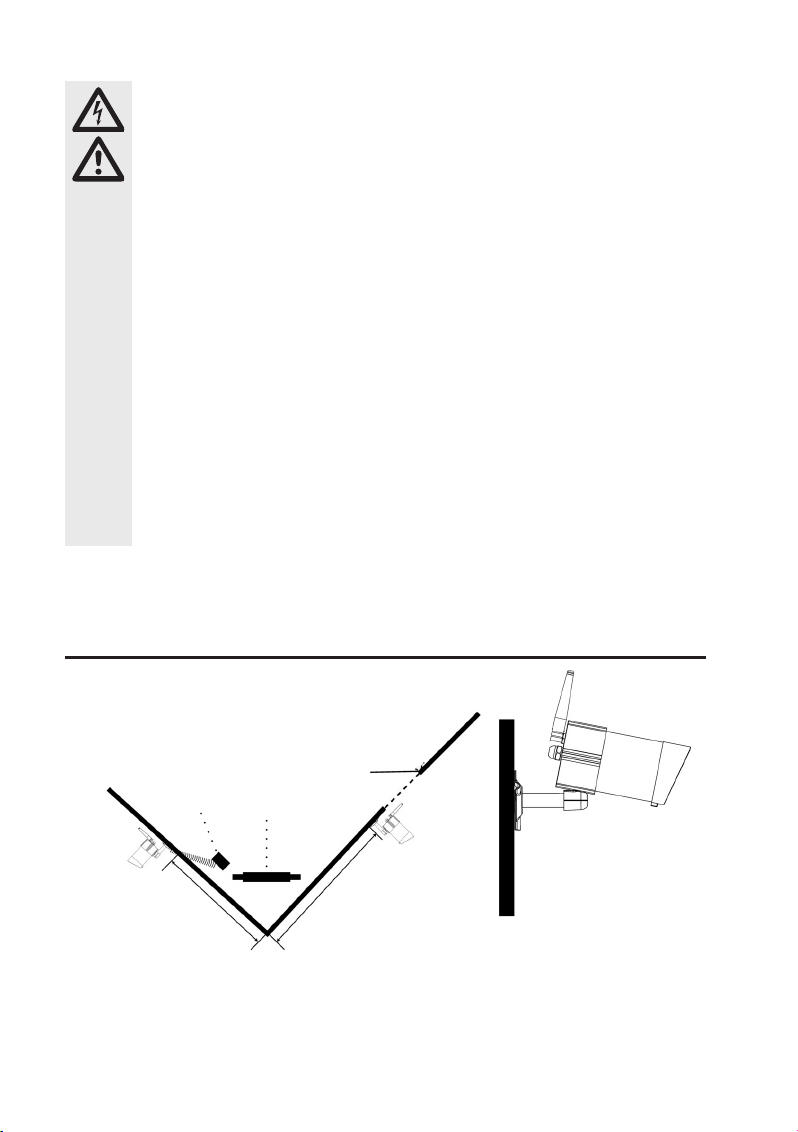
99
Ꮨ
• Ne touchez pas la fiche du bloc d’alimentation lorsque ce dernier est endommagé : il y a
danger de mort par électrocution !
• Coupez d’abord la tension du secteur pour la prise de courant sur laquelle le bloc d’alimentation est branché (éteindre par ex. le coupe-circuit automatique correspondant ou
dévisser le fusible, éteindre le disjoncteur différentiel correspondant de manière à ce que
tous les pôles de la prise de courant soient débranchés de la tension du secteur).
Débranchez ensuite d’abord le bloc d’alimentation de la prise de courant. Éliminez le bloc
d’alimentation défectueux en respectant les impératifs écologiques ; ne l’utilisez plus.
Remplacez-le par un bloc d’alimentation neuf aux spécifications identiques.
• En cas d’insertion incorrecte de la pile dans la télécommande à infrarouge, il y a danger d’explosion. La pile fournie doit uniquement être remplacée par une pile du même type ou un produit équivalent. N’exposez jamais la pile à une forte chaleur.
• Utilisez uniquement le produit dans les régions à climat modéré, pas dans les régions à
climat tropical.
• Dans les installations industrielles, il convient d’observer les consignes de prévention des
accidents relatives aux installations et moyens d’exploitation électriques, édictées par le syndicat professionnel.
• Ne laissez pas le matériel d’emballage sans surveillance, il pourrait constituer un jouet
dangereux pour les enfants.
• Ce produit doit être manipulé avec précaution – les coups, les chocs, ou une chute,
même d’une faible hauteur, peuvent l’endommager.
6. La disposition optimale des caméras, de l’unité
intérieure et du moniteur
Au sein d’un environnement ouvert, sans obstacles, comme par ex. les murs, le signal
radio de la caméra de surveillance a une portée maximale de 150 mètres.
La distance entre la caméra de surveillance et la prise de courant ne doit pas
être supérieure à la longueur du câble du bloc d’alimentation de la caméra de
surveillance. N’utilisez pas de rallonge.
Trou de 15 mm de diamètre dans le
mur pour l’introduction des câbles et
connecteurs à l’intérieur de la caméra.
Max. 5 mMax. 5 m
Porte d’entrée
TV / moniteur
Unité intérieure
(DVR / moniteur)
Caméra de
surveillance 2
Caméra de
surveillance 1
☞
Page 100

100
7. Installation
a) Remarques
• N’exposez pas les appareils et la pile de la télécommande à infrarouge à des températures élevées.
N’installez pas l’unité intérieure à proximité de radiateurs.
• L’unité intérieure et les blocs d’alimentation doivent exclusivement être utilisés à l’intérieur.
• La caméra de surveillance peut également être utilisée en plein air. Elle ne doit toutefois pas être utilisée dans l’eau ni être immergée.
• Évitez toute exposition directe directe au soleil de la caméra de surveillance.
• Évitez les vibrations.
• Installez la caméra de surveillance et l’unité intérieure à un emplacement bien aéré.
• Il est interdit d’ouvrir la caméra de surveillance et l’unité intérieure.
• Le cas échéant, la carte mémoire MicroSD 2 Go peut être remplacée par une carte mémoire
microSDHC avec une capacité maximale de 32 Go.
b) Positionnement de la caméra de surveillance
N’orientez pas directement la (ou les) caméra(s) de surveillance vers le soleil ou vers les arbres, les
buissons et branches qui se déplacent avec le vent : la détection des mouvements pourrait sinon accidentellement déclencher un enregistrement vidéo.
Le système propose une fonction « Camouflages » qui permet d’exclure certaines zones de l’image
capturée par la détection des mouvements de la caméra de surveillance.
c) Fonction de vision nocturne
La caméra de surveillance est munie de DEL infrarouges intégrées et permet ainsi également une surveillance durant la nuit. Les DEL infrarouges s’allument automatiquement dès qu’il fait nuit. L’image en
couleur sur l’unité intérieure passe alors au noir et blanc. La portée des DEL infrarouges s’élève 5 - 8 m.
d) Installation de la (ou des) caméra(s) de surveillance
Vissez l’antenne fournie au dos de la caméra de surveillance puis orientez-la à la verticale pour une qualité optimale de connexion.
Ꮨ
Assurez-vous que le mur sur lequel vous souhaitez installer la caméra de surveillance ne
contienne pas de conduites électriques ou conduites d’eau afin d’éviter des dommages
durant le perçage des trous requis.
 Loading...