

Page 1

15007-3 Conrad Adventskalender Internet of Things 2017_en.indd 115007-3 Conrad Adventskalender Internet of Things 2017_en.indd 1 13.08.2017 17:02:5213.08.2017 17:02:52
Page 2

I
.
3
Source codes and additiona
3
3
.
3
.
. . . . . . . . . . . . . . . . . . . . . . . . . . . . . . . . .
.
.
. . . . . . . . . . . . . . . . . . . . . . . . . . . . . . . . .
. . . . . . . . . . . . . . . . . . . . . . . . . . . . . . . .
0
gram
0
0
. . . . . . . . . . . . . . . . . . . . . . . . . . . . . . . . .
fl
....................................................................
2
. . . . . . . . . . . . . . . . . . . . . . . . . . . . . . . .
2
2
2
2
....................................................................
3
. . . . . . . . . . . . . . . . . . . . . . . . . . . . . . . .
g
. . . . . . . . . . . . . . . . . . . . . . . . . . . . . . . .
m
h
....................................................................
. . . . . . . . . . . . . . . . . . . . . . . . . . . . . . . .
.
.
.
. . . . . . . . . . . . . . . . . . . . . . . . . . . . . . . .
etc
board
. . . . . . . . . . . . . . . . . . . . . . . . . . . . . . . .
n
d
..................................................................
. . . . . . . . . . . . . . . . . . . . . . . . . . . . . . . .
p
.
lle Versuche im Überblick
. . . . . . . . . . . . . . . . . . . . . . . . . . . . . . . .
7
7
7
7
. . . . . . . . . . . . . . . . . . . . . . . . . . . . . . . .
p
.................................................................
. . . . . . . . . . . . . . . . . . . . . . . . . . . . . . . .
dell
.
. . . . . . . . . . . . . . . . . . . . . . . . . . . . . . . .
s
. . . . . . . . . . . . . . . . . . . . . . . . . . . . . . . .
...................................................................
. . . . . . . . . . . . . . . . . . . . . . . . . . . . . . . .
y of
h
h
..................................................................
. . . . . . . . . . . . . . . . . . . . . . . . . . . . . . . .
t
h
p
.................................................................
. . . . . . . . . . . . . . . . . . . . . . . . . . . . . . . .
.
. . . . . . . . . . . . . . . . . . . . . . . . . . . . . . . .
h
h
. . . . . . . . . . . . . . . . . . . . . . . . . . . . . . . . . . . . . . . . . . . . . .
h
. . . . . . . . . . . . . . . . . . . . . . . . . . . . . . . .
Sketch
.
. . . . . . . . . . . . . . . . . . . . . . . . . . . . . . . .
h
p
. . . . . . . . . . . . . . . . . . . . . . . . . . . . . . . . . . . . . . . . . . . . . . . .
.................................................................
0
. . . . . . . . . . . . . . . . . . . . . . . . . . . . . . . .
0 breaker
0
p
0
2
. . . . . . . . . . . . . . . . . . . . . . . . . . . . . . . .
h
p
nternet of Things Advent Calendar 2017 ...................
l information . . . . . . . . . . . . . . . . . . . . . . . .
Background knowledge on the components . . . . . . . . . . . . . . . . . . . . . .
LEDs . . . . . . . . . . . . . . . . . . . . . . . . . . . . . . . . . . . . . . . . . . . . . . . . . . .
Resistors and their colour codes . . . . . . . . . . . . . . . . . . . . . . . . . . . . . . . 4
1st Day .....................................................................
Confi guring the IoT-board . . . . . . . . . . . . . . . . . . . . . . . . . . . . . . . . . . . .
Step 1: Installation of the driver for the IoT-board . . . . . . . . . . . . . . . . . .
Step 2: Installation of the Arduino IDE . . . . . . . . . . . . . . . . . . . . . . . . . .
Update of the fi rmware on the IoT-board . . . . . . . . . . . . . . . . . . . . . . .
Testing the IoT-board . . . . . . . . . . . . . . . . . . . . . . . . . . . . . . . . . . . . . . .
Making the on-board-LED fl ash . . . . . . . . . . . . . . . . . . . . . . . . . . . . . . .
2nd Day ...................................................................
Measuring analogue values . . . . . . . . . . . . . . . . . . . . . . . . . . . . . . . . . .
The program . . . . . . . . . . . . . . . . . . . . . . . . . . . . . . . . . . . . . . . . . . . . .
How the program works . . . . . . . . . . . . . . . . . . . . . . . . . . . . . . . . . . . . .
3rd Day....................................................................0
Flashing light . . . . . . . . . . . . . . . . . . . . . . . . . . . . . . . . . . . . . . . . . . . . 10
The pro
How the program works . . . . . . . . . . . . . . . . . . . . . . . . . . . . . . . . . . . . 1
. . . . . . . . . . . . . . . . . . . . . . . . . . . . . . . . . . . . . . . . . . . . 1
4th Day .....................................................................11
Alternating
The program . . . . . . . . . . . . . . . . . . . . . . . . . . . . . . . . . . . . . . . . . . . . .
How the program works . . . . . . . . . . . . . . . . . . . . . . . . . . . . . . . . . . . . .11
5th Day
Traffi c light . . . . . . . . . . . . . . . . . . . . . . . . . . . . . . . . . . . . . . . . . . . . . . 1
Installing Snap! and preparing the IoT-board . . . . . . . . . . . . . . . . . . . . 1
Implementing a program in Snap! . . . . . . . . . . . . . . . . . . . . . . . . . . . . 1
6th Day
Connection to the IoT-board . . . . . . . . . . . . . . . . . . . . . . . . . . . . . . . . .
Installin
The program . . . . . . . . . . . . . . . . . . . . . . . . . . . . . . . . . . . . . . . . . . . .
ash . . . . . . . . . . . . . . . . . . . . . . . . . . . . . . . . . . . . . . . . . . .
1
1
the App for control . . . . . . . . . . . . . . . . . . . . . . . . . . . . . . . .
7th Day....................................................................15
Controllable running light . . . . . . . . . . . . . . . . . . . . . . . . . . . . . . . . . . .
The progra
How t
. . . . . . . . . . . . . . . . . . . . . . . . . . . . . . . . . . . . . . . . . . . .
e program works . . . . . . . . . . . . . . . . . . . . . . . . . . . . . . . . . . . .
8th Day
Outputting sounds through the App . . . . . . . . . . . . . . . . . . . . . . . . . . .
Development environment for the Apps . . . . . . . . . . . . . . . . . . . . . . . .
Your fi rst App with AI2 . . . . . . . . . . . . . . . . . . . . . . . . . . . . . . . . . . . . .
Controlling the piezo with the App . . . . . . . . . . . . . . . . . . . . . . . . . . . .
Function of the App . . . . . . . . . . . . . . . . . . . . . . . . . . . . . . . . . . . . . .
Testing the App . . . . . . . . . . . . . . . . . . . . . . . . . . . . . . . . . . . . . . . . . .
9th Day ...................................................................
RGB-LEDs . . . . . . . . . . . . . . . . . . . . . . . . . . . . . . . . . . . . . . . . . . . . . . .
Changing the colour of an RGB-LED with the App . . . . . . . . . . . . . . . . .
The Sk
The App . . . . . . . . . . . . . . . . . . . . . . . . . . . . . . . . . . . . . . . . . . . . . . . .
h for the IoT-
. . . . . . . . . . . . . . . . . . . . . . . . . . . . . . . .
10th Day ..................................................................25
Displaying the push of a butto
The Sketch . . . . . . . . . . . . . . . . . . . . . . . . . . . . . . . . . . . . . . . . . . . . . .
Displaying the reaction of the IoT-boar
. . . . . . . . . . . . . . . . . . . . . . . . . . . . . .
. . . . . . . . . . . . . . . . . . . . . . . .
11th Day
LED echo by App . . . . . . . . . . . . . . . . . . . . . . . . . . . . . . . . . . . . . . . . .
The Sketch . . . . . . . . . . . . . . . . . . . . . . . . . . . . . . . . . . . . . . . . . . . . . .6
The Ap
. . . . . . . . . . . . . . . . . . . . . . . . . . . . . . . . . . . . . . . . . . . . . . .
12th Day...................................................................
Setting the running light speed by App . . . . . . . . . . . . . . . . . . . . . . . . . 2
The Sketch. . . . . . . . . . . . . . . . . . . . . . . . . . . . . . . . . . . . . . . . . . . . . . 2
The App . . . . . . . . . . . . . . . . . . . . . . . . . . . . . . . . . . . . . . . . . . . . . . . . 2
13th Day .................................................................. 28
Adjusting RGB via a slider in the App . . . . . . . . . . . . . . . . . . . . . . . . . . 28
The Sketch . . . . . . . . . . . . . . . . . . . . . . . . . . . . . . . . . . . . . . . . . . . . . . 28
The Ap
. . . . . . . . . . . . . . . . . . . . . . . . . . . . . . . . . . . . . . . . . . . . . . . . 29
14th Day
Mo
ing clay contact . . . . . . . . . . . . . . . . . . . . . . . . . . . . . . . . . . . .
This is how sensor contacts work: . . . . . . . . . . . . . . . . . . . . . . . . . . . .
The Sketch . . . . . . . . . . . . . . . . . . . . . . . . . . . . . . . . . . . . . . . . . . . . . .
The App. . . . . . . . . . . . . . . . . . . . . . . . . . . . . . . . . . . . . . . . . . . . . . . .
15th Day ...................................................................
Differentiable modelling clay contact
1
The Sketch . . . . . . . . . . . . . . . . . . . . . . . . . . . . . . . . . . . . . . . . . . . . . .
The App. . . . . . . . . . . . . . . . . . . . . . . . . . . . . . . . . . . . . . . . . . . . . . . . 32
. . . . . . . . . . . . . . . . . . . . . . . . .
16th Day ..................................................................
ontrolling the fl ashing LED with the App . . . . . . . . . . . . . . . . . . . . . . .
11
The Sketch . . . . . . . . . . . . . . . . . . . . . . . . . . . . . . . . . . . . . . . . . . . . . .
The App . . . . . . . . . . . . . . . . . . . . . . . . . . . . . . . . . . . . . . . . . . . . . . . .
17th Day
Displa
1
T
T
the resistor value . . . . . . . . . . . . . . . . . . . . . . . . . . . . . . . . .
e Sketch. . . . . . . . . . . . . . . . . . . . . . . . . . . . . . . . . . . . . . . . . . . . . .
e App . . . . . . . . . . . . . . . . . . . . . . . . . . . . . . . . . . . . . . . . . . . . . . . .
18th Day
3
RGB-running ligh
T
e Sketch . . . . . . . . . . . . . . . . . . . . . . . . . . . . . . . . . . . . . . . . . . . . . .5
The Ap
. . . . . . . . . . . . . . . . . . . . . . . . . . . . . . . . . . . . . . . . . . . . . . . . 35
. . . . . . . . . . . . . . . . . . . . . . . . . . . . . . . . . . . . . . . . .
19th Day
App to select hardware Apps . . . . . . . . . . . . . . . . . . . . . . . . . . . . . . . .
The Sketch. . . . . . . . . . . . . . . . . . . . . . . . . . . . . . . . . . . . . . . . . . . . . .
5
The App . . . . . . . . . . . . . . . . . . . . . . . . . . . . . . . . . . . . . . . . . . . . . . .
5
20th Day ..................................................................
Heat sensor in the App . . . . . . . . . . . . . . . . . . . . . . . . . . . . . . . . . . . . .
T
e Sketc
T
e App . . . . . . . . . . . . . . . . . . . . . . . . . . . . . . . . . . . . . . . . . . . . . . . .
21st Day ..................................................................
Measuring brightness and darkness in the App . . . . . . . . . . . . . . . . . .
The
The App . . . . . . . . . . . . . . . . . . . . . . . . . . . . . . . . . . . . . . . . . . . . . . .
. . . . . . . . . . . . . . . . . . . . . . . . . . . . . . . . . . . . . . . . . . . . . .
22nd Day .................................................................
Moisture measurement . . . . . . . . . . . . . . . . . . . . . . . . . . . . . . . . . . . .9
The Sketch . . . . . . . . . . . . . . . . . . . . . . . . . . . . . . . . . . . . . . . . . . . . . .
T
e Ap
23rd Day
5
5
The Sketch . . . . . . . . . . . . . . . . . . . . . . . . . . . . . . . . . . . . . . . . . . . . . .40
5
The Ap
5
. . . . . . . . . . . . . . . . . . . . . . . . . . . . . . . . . . . . . . . . . . . . 4
. . . . . . . . . . . . . . . . . . . . . . . . . . . . . . . . . . . . . . . . . . . . . . . . 4
24th Day .................................................................. 4
Reaction game . . . . . . . . . . . . . . . . . . . . . . . . . . . . . . . . . . . . . . . . . . .42
T
e Sketch . . . . . . . . . . . . . . . . . . . . . . . . . . . . . . . . . . . . . . . . . . . . . .42
The Ap
. . . . . . . . . . . . . . . . . . . . . . . . . . . . . . . . . . . . . . . . . . . . . . . . 42
28
30
30
32
35
4
4
42
7
2
1
2
3
4
4
4
4
5
7
7
7
7
7
9
9
15007-3 Conrad Adventskalender Internet of Things 2017_en.indd 215007-3 Conrad Adventskalender Internet of Things 2017_en.indd 2 13.08.2017 17:02:5613.08.2017 17:02:56
Page 3
Internet of Things Advent Calendar 201
7
-
n
the code
5007-3
oad there
f
the archive.
d
s
.
-
-
d
.
x
If Cisco has its way, more than 50 billion linked devices will be used by 2020; even more optimistically,
Intel expects 200 billion devices1. Each of these devices – or “things” – has a unique address and communicates with the outside world through the internet or through some other interfaces, such as Blue
tooth: From the coffee machine to the fridge, from the car to the train, from the production machine to
the bracelet: everything can be programmed and can communicate with other things. This topic is more
than just a hype. It is becoming the state of the art, and we should all be dealing with it. Use the Advent
season and get into the Internet of Things (IoT). 24 experiments will introduce you to the subject and let
you program your own thing. Have fun!
Source codes and additional informatio
In the next 24 days, you will learn many new things about the subject of IoT (Internet of Things) and
implement exciting projects. So that you won’t have to type down the programs, some of which can
be rather large, we procured the entire source codes and any additional information for download. Go
ttp://www.buch.cd and enter
archive contains a separate directory for every day. For detailed information, read the fi le Liesmich.pd
in
Some of the programs from day 8 onwards are very large and not printed in full here. Only those parts of
the project that you must have to understand and implement it are described in the handbook. Projects
that are controlled with the dedicated Smartphone app are available for download in full. If you want to
make any changes to the program, always have a look at the fi nished program fi rst; then make a copy of
it and modify the copy. If anything goes wrong, you can get the initial fi les from
1
You will fi nd an archive for downl
ttp://www.buch.c
. The
Updates in the download area
The advent calendar was created long before Advent and is based on program versions from that
time. If any greater changes occur before Advent, you can fi nd an update of the affected projects in the
ownload area.
Background knowledge on the component
Every compartment contains one component. Here, we will provide the most important information on
the components
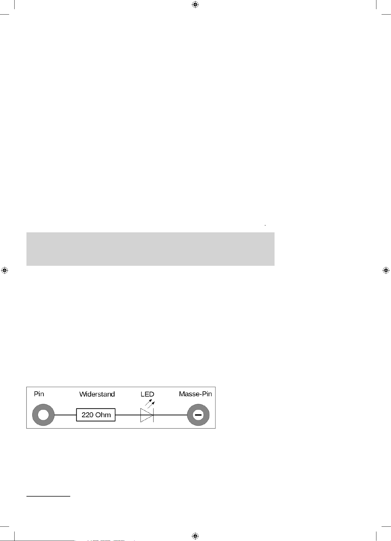
LEDs (light-emitting diodes) are lit when power runs through them in the fl ow direction. LEDs are illus
trated in circuits with an arrow-shaped triangle that indicates the current direction from the plus to the
minus pole or to the ground line. An LED lets through nearly any amount of power in the fl ow direction,
and has only a very small resistance. I order to limit the fl ow current and to prevent the LED from burn
ing through, one usually must install a 220Ohm dropping resistor between the connection pin used an
the anode of the LED or between the cathode and the ground pin. This dropping resistor also protects
the output of the included IoT-board from too-high currents. The LEDs in the Advent calendar have the
dropping resistor already installed, and therefore can be connected directly to the pins of the IoT board
Circuit diagram of an LED with a dropping resistor
1
ource: https://www.fool.com/investing/general/2016/01/18/internet-of-things-in-2016-6-stats-everyone-should.asp
15007-3 Conrad Adventskalender Internet of Things 2017_en.indd 315007-3 Conrad Adventskalender Internet of Things 2017_en.indd 3 13.08.2017 17:02:5713.08.2017 17:02:57
Page 4
n which direction is the LED connected?
-
s
-
.
.
,
t.
r
g
)
)
g
er10
0%
1
%
1
0
%
00
%
0llow
0
000
n
000
%
000.000
%
t
000.000
e10
000.000.000
The two connection wires of an LED are differently long. The longer one is the plus pole, the anode, the
horter one the cathode. It‘s easy to remember: The plus has one dash more than the minus and there
fore also makes the wire a bit longer. Most LEDs are also fl attened on the minus side, like a minus
ign. It‘s easy to remember: Cathode = short = edge.
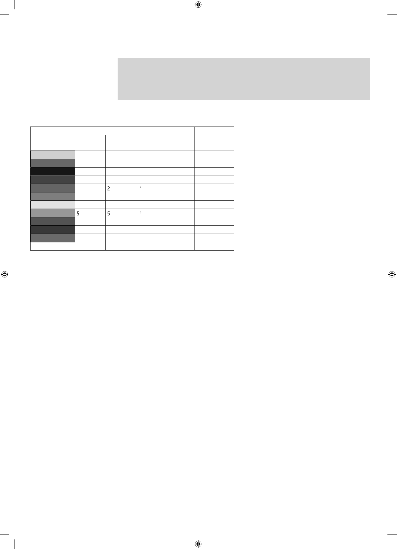
Resistors and their colour code
Colou
ilv
Gold 10
Black
Brown
Red 2
Orange 3310
ree
Blue
iole
Grey
Whit
Resistance in Ohm
. Rin
(tens
. Ring
ones)
. Ring
multiplier
= 0,01±1
= 0,
10 =
10 = 1
10 = 1
= 1.00
4
1
= 10.
10 = 100.
10 = 1.
10
= 10.000.000 ±0,1%
10 = 100.
= 1.
reading direction clear. The tolerance value is hardly relevant in digital electronics. The table shows the
meaning of the coloured rings on resistors.
. Rin
tolerance)
±5
±1
±2
±0,5
±0,25
±0,05%
esistors are used to limit current at sensitive elec
ronic components and as dropping resistors for
EDs. The unit of measurement for resistors is Ohm.
,000Ohm make one Kiloohm, in short: kOhm.
,000kOhm make one Megaohm, in short: MOhm.
he unit Ohm is often represented by the Omega
aracter Ω
e coloured rings on the resistors indicate the
esistance. They are much easier to recognise than
iny fi gures that can still be found only on very old
esistors. With a little practice, you can “translate”
he values from the colour codes quite quickly
ost resistors have four such colour rings. The fi rst
wo colour rings represent the digits, the third one is
a multiplier and the fourth the tolerance. This tolerance ring is usually golden or silver – colours that
o not appear in the fi rst two rings. This makes the
It doesn’t matter in which direction the resistor is installed. The installation direction of LEDs, in contrast
is relevan
15007-3 Conrad Adventskalender Internet of Things 2017_en.indd 415007-3 Conrad Adventskalender Internet of Things 2017_en.indd 4 13.08.2017 17:02:5713.08.2017 17:02:57
Page 5
1st Da
y
y
2
.
-
.
d
E
d
:
h.
.
E
.
E
.
.
r
In the Advent calendar toda
1x IoT Bluething board
Today, you will get to know the board with which you will implement the projects of the next 24 days. To
prepare for the next days, you will install the driver for the USB connection, install the
rduino IDE and fi nally create your fi rst program for the board
Chipset on the IoT-board
The IoT-board comes with two chipsets. For program execution, the board has an ATmega328P. This
micro controller communicates with an HC-05 via a serial interface. The HC-05 is responsible for the
wireless connection (Bluetooth). The module supports Bluetooth V2.0+EDR. You will need a Smart
hone with Android for App communication.
Confi guring the IoT-board
In order to take the IoT-board into operation, you need a computer with Linux, MacOSX or Windows
nd a Micro-USB-cable. This connection cable serves power supply and connection of the IoT-board to
the PC in order to program it. You do not need to buy such a cable. You probably have one already –
lmost all modern Smartphones use this plug type
Select the proper USB-port at the PC
Connect the cable to a USB 2.0 connection of your PC if you can. USB-3.0 connections may have connection problems. You can often recognise a USB-3.0-connection by the blue socket.
1. Day
Before connecting the board to a PC, complete the following steps:
Step 1: Installation of the driver for the IoT-boar
Step 2: Installation of the Arduino ID
Step 1: Installation of the driver for the IoT-boar
The USB port on the IoT-board is connected to a CH340G-chipset. In order to use
this chipset for a USB connection, you need to install the matching driver for your
perating system. Perform the following four steps for this
1 Download the example programs and the drive drivers from
cd. Enter the code
5007-3 there and follow the instructions on the screen.
ttp://www.buc
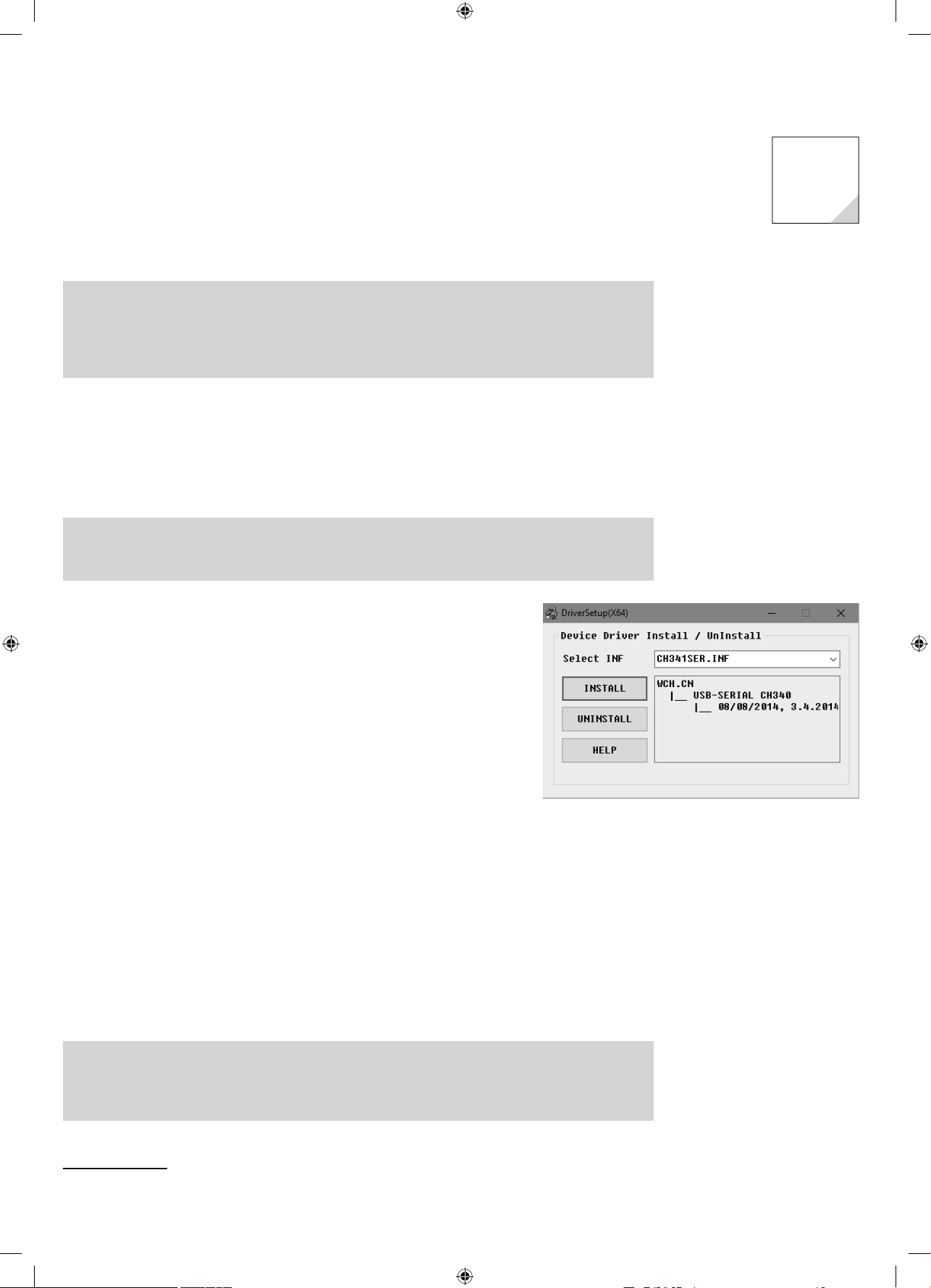
Installation of the device drive
2 Unpack the ZIP archive into any folder under your user folder
Connect the IoT-board via the USB-cable and start the driver installation with the fi le
H341SER.EX
.
You may need to confi rm a query from the Windows user account control for installation
In the installation dialogue, clickInstall and wait until driver installation is confi rmed.
Step 2: Installation of the Arduino ID
The IoT-board is compatible with the Arduino Nano and can be programmed with the Arduino IDE3. In
the Arduino IDE, you can write the programs in the programming language C and transfer them directly
to the IoT-board. After transfer, the program will run without any connection to the PC, which means that
you may disconnect the board.
Switching off the IoT-board
The IoT-board has no off-switch. You just need to disconnect the USB-cable from the computer PC or
the mains unit, and the IoT-board will switch off. The last saved program will start automatically when
the board is switched on again. The same happens if you push the reset button
2Called the IoT-board below.
3 The Arduino IDE in version 1.8.2 has been used for the projects. If a newer version is available by the time the Advent calendar is
sold, you can use it instead. If there are any distinctive changes, you will fi nd a corresponding note in the download area
15007-3 Conrad Adventskalender Internet of Things 2017_en.indd 515007-3 Conrad Adventskalender Internet of Things 2017_en.indd 5 13.08.2017 17:02:5713.08.2017 17:02:57
Page 6
Download the Windows Installer for the current version of the Arduino IDE from
e
.
-
d
choose
ools
t
in the Arduino IDE menu. Only a single serial port is usually displayed here.
use the menu ite
ect the
-
ust be chosen as CPU
n
e
oad the
board
use the icons
stead: Use the arrow to
.
the IoT-
d.
.
stallation of the
E
d
www.arduino.cc/en/Main/Softwareor use the fi le
rduino-windows.ex
from the
downloads for the Advent calendar. Under Windows10, you can also download
the Arduino IDE from the Windows Store and install it from there
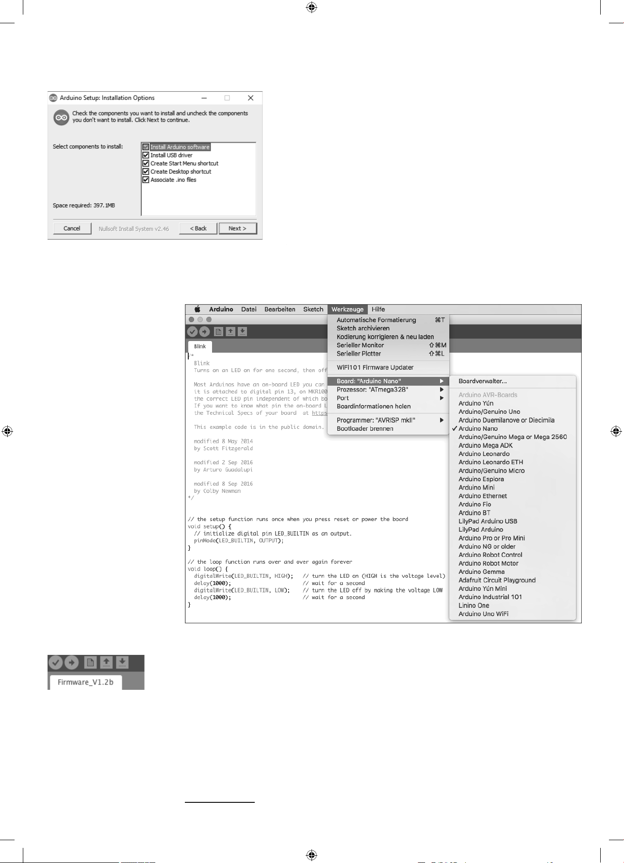
Make sure that all boxes are checked in the dialogue fi eld Installation Options
Depending on the Windows confi guration, the user account control must be con
rmed.
Update of the fi rmware on the IoT-boar
To enable you to reproduce all experiments with your IoT-board, fi rst update the
fi rmware on your board. For this, fi rst open the previously installed Arduino IDE
nd
In
Arduino ID
r
heck this.
T
/
Then
cally.
mega328 m
m
ls/Board to sel
.
Arduino Nano if it has not been recognised automati
Choose the right board in the Arduino IDE
After starting the Arduino IDE and selecting the board, open the fi rmware Firmware_V1.2b.ino now via
he menu item File/Open... It can be found in the download archive, directory Firmware_V1.2b Befor
ou install the fi rmware, ensure that the jumper on the IoT board is set to AT L
Quick start of the fi rmware
ownload onto the boar
he
the right to load the fi rmware4 onto the board
After a short time, the status line of the editor should show the messageUpload complete Now
viaSketch/Upload. You can also
oard has been update
4 The fi rmware is a regular Arduino-program. Such an Arduino-program is called a Sketch
15007-3 Conrad Adventskalender Internet of Things 2017_en.indd 615007-3 Conrad Adventskalender Internet of Things 2017_en.indd 6 13.08.2017 17:02:5713.08.2017 17:02:57
fi rmware onto
in the editor for this in
Page 7
Testing the IoT-board
y-
.
-
.
d.
d.
h
.
g.
.
.
d.
ection can be established
out a ne
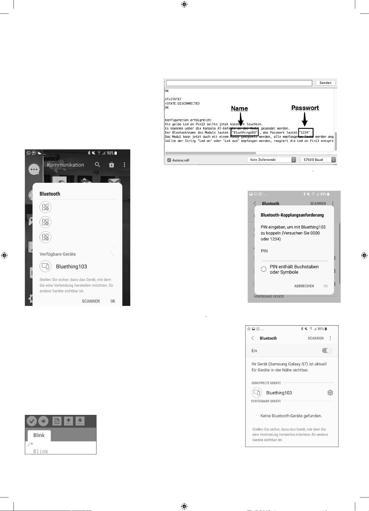
fter updating the fi rmware, you can now test the board. For this, open the serial monitor of the Arduino
IDE via Tools/Serial Monitor. Set the data transmission to 57600 Baud. Now you should see legible text
in the output window. Finally, there will be an output sa
ing Confi guration successful!, followed by information on
the wireless network
Now you can use your Android Smartphone to test whether
you can see the wireless network. For this, switch on Blue
tooth on your Smartphone; the wireless network should
appear after a short time. Now select the wireless network
(in the following screen shot: Bluething103) and confi rm
your selection with
K.
The name of the network in this example is Bluething103 and the password is 1234
On your system, the name of the IoT-board will also
tart with Bluething, but may end on a different
umber. The number is generated individually
ased on the MAC address of your board
ou must enter a password for establishing the connection; in this case, it is
fter entering the proper password, the network will appear in
NNECTED DEVICES.
234
Now your Smartphone can communicate with your IoT-boar
On your system, the name of the IoT-board will also start with Bluething, but may end on a
different number. The number is generated individually based on the MAC address of your
oar
Making the on-board-LED fl as
Now we want to test programming of the IoT-board. We use the fl ash Sketch integrated into the
rduino IDE as an example. For this, choose Datei/Beispiele/01.Basics/Blink in the menu
Now click the round icon with the arrow at the upper left, in order to upload the program to the
connected IoT-board, which is also called fl ashin
Use the check mark to compile the data;
the arrow to the right uploads the program to the IoT-board
fter the upload is complete, the LED D2 (next to connection D13) on the IoT-board will fl ash.
Now the board is ready for the next days
ou must enter a password to connect to the IoT-
r
Once a device has been connected to a Smartphone,
he conn
n.
with
w
15007-3 Conrad Adventskalender Internet of Things 2017_en.indd 715007-3 Conrad Adventskalender Internet of Things 2017_en.indd 7 13.08.2017 17:02:5813.08.2017 17:02:58
Page 8
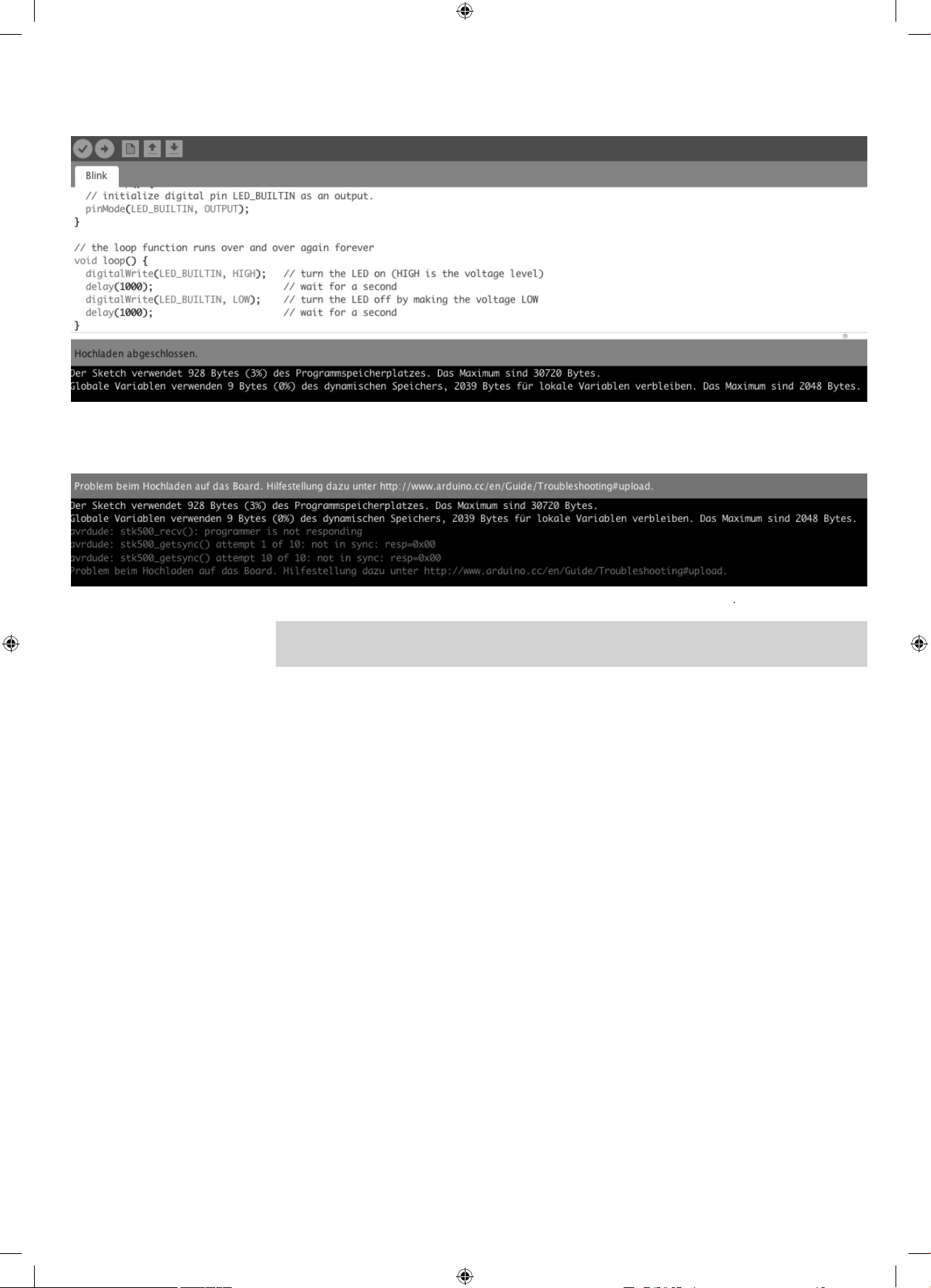
Below the source code window, you can see the outputs of the Arduino IDE when compiling and uploading
.
t
.
If the LED does not fl ash, look at the error messages in the Arduino IDE.
he connection to the IoT-board has failed here. In this case, you have chosen the wrong port; this can be fi xed quickly in the menu itemTools/Por
Always use the IoT-board in AT mode
The IoT-board has a Jumper. This jumper must be set to
for all projects in this calendar
15007-3 Conrad Adventskalender Internet of Things 2017_en.indd 815007-3 Conrad Adventskalender Internet of Things 2017_en.indd 8 13.08.2017 17:03:0013.08.2017 17:03:00
Page 9
2nd Da
y
)
s
)
m
d l
h
.
.
;
;
{
;
{
;
(
);
ks
;
in
d
p
{
;
);
p
)
p()
p
.
p()
;
d
e
p
al.
)
000
seconds.
aud
y
In the Advent calendar today
•1x board (SYB 46
•1x jumper cable
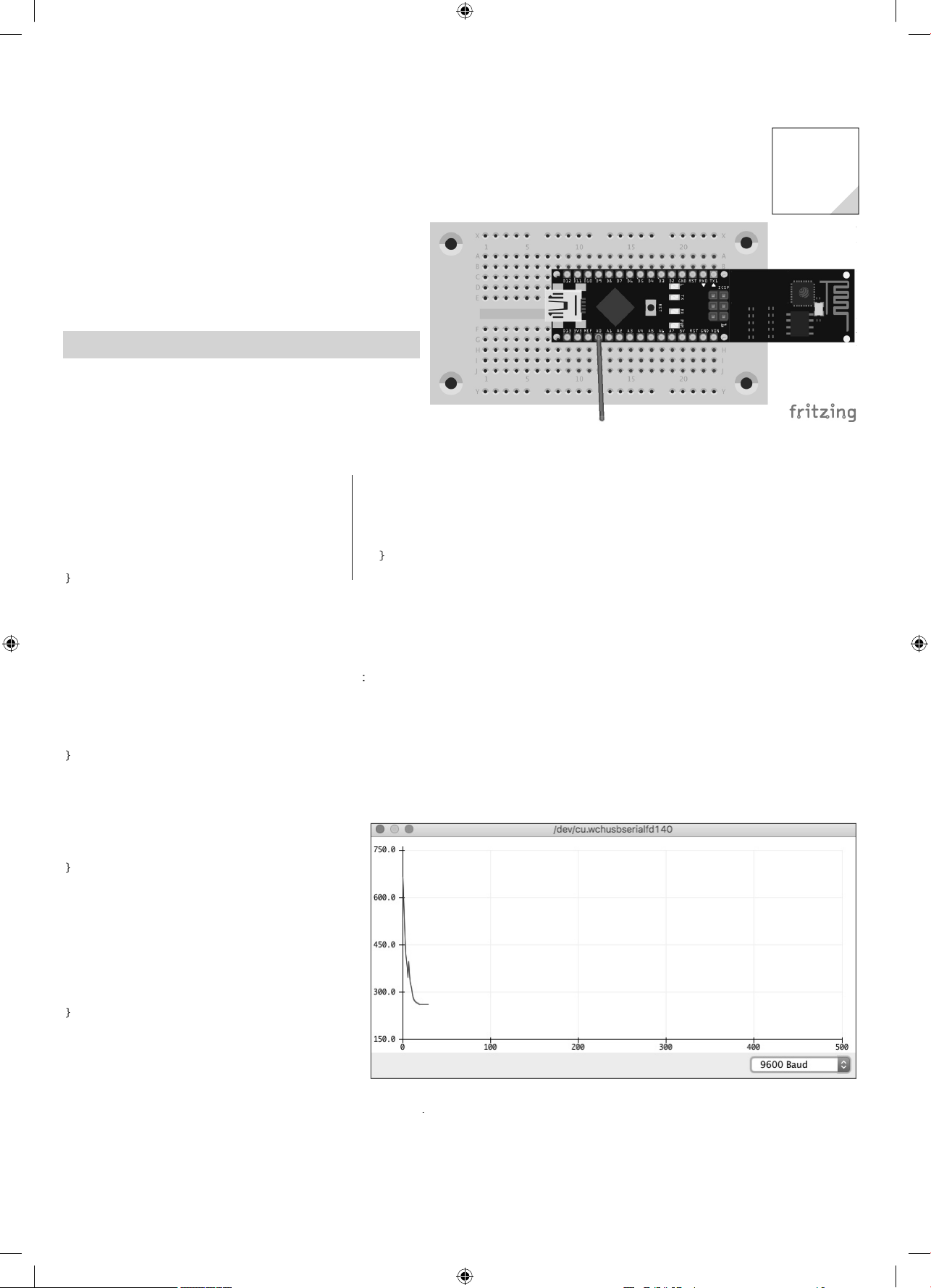
Measuring analogue value
Today, you will program a Sketch in the Arduino IDE to read
out the values of an analogue input. The values will be graphically displayed by text output.
omponents: 1x board, 1xjumper cable (male – male
The progra
The program for this day is called
irectory
int analogValue = 0
int analogPin = A0
oid setup()
pinMode(analogPin, INPUT)
Serial.begin(9600);
ag02 wit
in the download archive
ag02.ino an
ocated in
oid loop()
analogValue = analogRead(analogPin)
Serial.println(analogValue);
delay
2. Da
The jumper cable serves as an antenna. Try measurements without its cable as well, to see if
the cable makes a difference to your measuring environment
1000
How the program wor
int analogPin = A0
First, the pin number used is specifi ed in the variable
made up at least of the two functions
oid setup()
pinMode(analogPin, INPUT)
Serial.begin(9600
The function
as the input.
etu
runs once initially and is usually used for confi guration. The analogue pin is specifi ed
erial.begin(9600
etup
n
starts serial communication in order to display values on the serial
monitor and the serial plotter. The parameter in this function is the Baud rate.
oid loo
The function
{
oo
is repeated until the power supply
is disconnected or the reset button pushed
oid loo
analogValue = analogRead(analogPin);
Serial.println(analogValue)
delay(1000);
{
loo
nalogP
All programs in the Arduino IDE are
analogRea
he variabl
rintlndelay(1000
1
saves the value of the analogue input in
nalogValue and out
uts it via
makes the program wait for
milli
ri
The data rate must be set correctly in the dropdown in the lower right corner of the window, in this case
B
Now, open the serial monitor via Tools/Serial Moni-
. You can see the measured value there. You can also have the values displayed graphically. For this,
connect the previously opened serial monitor and open the serial plotter via Tools/Serial plotter.
15007-3 Conrad Adventskalender Internet of Things 2017_en.indd 915007-3 Conrad Adventskalender Internet of Things 2017_en.indd 9 13.08.2017 17:03:0113.08.2017 17:03:01
Page 10
1
0
y
r
e
r
m
ino
;
;
{
);
{
;
;
);
;
;
able
lly
O
(
)
.
y
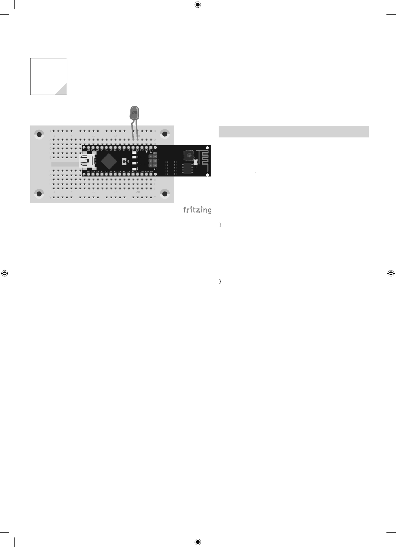
3rd Day
3. Da
In the Advent calendar toda
•1x LED red with dropping resisto
•1x switching wir
You do not need any separate resistor, since the LED already has an integrated one
lashing light
Today, you will make an LED fl ash at a frequency of 2Hz.
omponents: 1x board, 1xLED red with dropping resisto
e progra
The program for this day is called Tag03.
irectory
const int ledPin = 2
nt ledState = LOW
void setup()
pinMode(ledPin, OUTPUT
void loop()
if (ledState == LOW) ledState = HIGH
else ledState = LOW
digitalWrite(ledPin, ledState
delay(500)
ag03
and located in
How the program works
if (ledState == LOW) ledState = HIGH
else ledState = LOW;
The vari
value is switched every 500ms via delay
records whether the LED is lit or not. Initia
500
. This makes the LED fl ash.
, the variable has the value L
W
This
15007-3 Conrad Adventskalender Internet of Things 2017_en.indd 1015007-3 Conrad Adventskalender Internet of Things 2017_en.indd 10 13.08.2017 17:03:0113.08.2017 17:03:01
Page 11
4th Da
y
r
y.
-
r
m
d l
4
;
;
{
;
);
);
;
;
;
{
;
);
}
;
ks
;
;
;
;
}
i
hich
in1
.
.
In the Advent calendar today
•1x LED yellow with dropping resisto
Alternating fl ash
Two LEDs fl ash alternatingl
omponents: 1x board, 1xLED yellow with dropping resi
stor, 1xLED red with dropping resisto
The progra
The program for this day is called
irectory
const int ledPin1 = 10;
const int ledPin2 = 12;
nt ledState = LOW
nt pin = ledPin1
oid setup()
pinMode(ledPin1, OUTPUT)
pinMode(ledPin2, OUTPUT
digitalWrite(ledPin1, LOW
digitalWrite(ledPin2, LOW)
ag0
ag04.ino an
ocated in
4. Day
Both cathodes (short legs of the LED) must be connected to GND. The left one is the yellow LED,
the right one the red LED
oid loop() {
if (pin == ledPin1) {
pin = ledPin2
digitalWrite(ledPin1, LOW)
} else
pin = ledPin1
digitalWrite(ledPin2, LOW
digitalWrite(pin, HIGH);
delay(500)
How the program wor
if (pin == ledPin1) {
pin = ledPin2
digitalWrite(ledPin1, LOW)
} else {
pin = ledPin1
digitalWrite(ledPin2, LOW)
The temporary variable p
switches the variable to the other pin, and the currently lit LED is switched off. Switching takes place
every 500ms
n saves w
LED is currently lit. Initially this value is ledP
. An if-query
15007-3 Conrad Adventskalender Internet of Things 2017_en.indd 1115007-3 Conrad Adventskalender Internet of Things 2017_en.indd 11 13.08.2017 17:03:0213.08.2017 17:03:02
Page 12
5th Day
y
r
.
-
d
-
-
.
.
!
-
l
the element
ect to
.
-
oad the latest versio
.
.
y
5. Da
In the Advent calendar toda
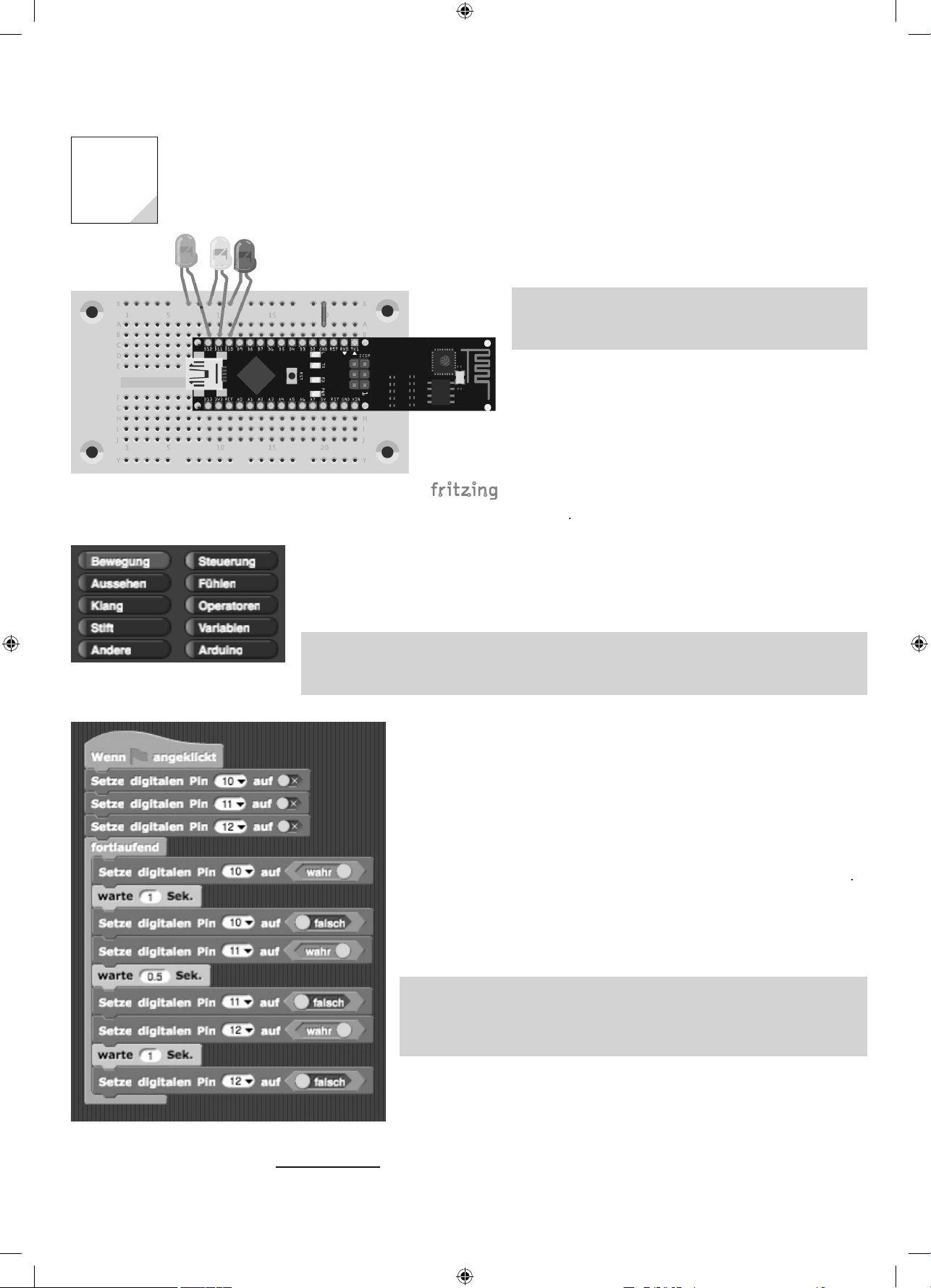
•1x LED green with dropping resisto
Starting at three LEDs, things get a little crowded, so that GND is separately connected to the
upper strip. LEDs from the left to the right: green, yellow and red.
need to install a special Sketch on your board: Firmata. For this, connect the IoT-board to your PC
nd open the Arduino IDE. Select File/Examples/Firmata/Standard Firmata and download the
Sketch to the board by clicking the arrow to the right. Now you can program the board with Snap4Arduino
raffi c light
oday’s project is a traffi c light that is created with the graphi-
cal development interface Snap!
omponents: 1x board, 1xLED green with dropping resistor,
xLED yellow with dropping resistor, 1xLED red with drop
ng resistor, 1xjumper
nstalling Snap! and preparing the IoT-boar
Snap! is a graphical development interface that exists specifi
cally for Arduino as well in the form of Snap4Arduino. Down-
oad the software version used for this calendar from
www.buch.cd5. After installation, switch the interface lan
guage to German. For this, click the settings icon (cogwheel) in
Snap4Arduino and choose the language
erman in the menu
anguage
n order to be able to use Snap4Arduino on your board, you
ttp://
e category Arduino contains the elements for
controlling the IoT-board.
o not use Arduino IDE and Snap! at the same time
he Arduino IDE and Snap! cannot be used at the same time. Therefore, close the respective other
rogram before you work in the desired environment
mplementing a program in Snap
A program is assembled in Snap! with graphical elements that are divided into
categories. The category menu can be found in the upper left.
ow pull the element with the green colour into the middle working area from
ontrol. Use the element Set digital pin in order to switch the LEDs on and off. Set
he values via the switchable element
gram from ending, you need the loop element from Control. To keep the LEDs from
witching again at once, include a break of one second using wait from Contro
efore starting the program, you need to connect the IoT-board to Snap!. For this,
ick
nn
Arduino in the categoryArduino. When clicking the
mbol, you will see the available connections. Select the fi rst connection. Now
click the green arrow (upper right), and the traffi c light will start
pening an external project in Snap!
he program for today is located in folder
enu bar and select
mport... Navigate to the folder
nap.xml The project is now open and you can use it.
rue from
ag05
perators To prevent the pro
Go to the fi rst symbol in the
ag05 and select tag05
he program created in Snap!
You can also downl
screen shots, but the programs should work the same
15007-3 Conrad Adventskalender Internet of Things 2017_en.indd 1215007-3 Conrad Adventskalender Internet of Things 2017_en.indd 12 13.08.2017 17:03:0213.08.2017 17:03:02
n from http://snap4arduino.org/ The interface may deviate slightly from the
Page 13
3
6th Da
y
r
.
r
.
m
o
e
.
y
and rename the
g
also
g
o
g
the
edPinBlue
:
3
2
tup
:
p()
...
);
g
:
)){
);
;
}
)){
;
;
}
board receives
ed o
O
d
-
switch the
.
.
y
y
1
In the Advent calendar today
•1x LED blue with dropping resisto
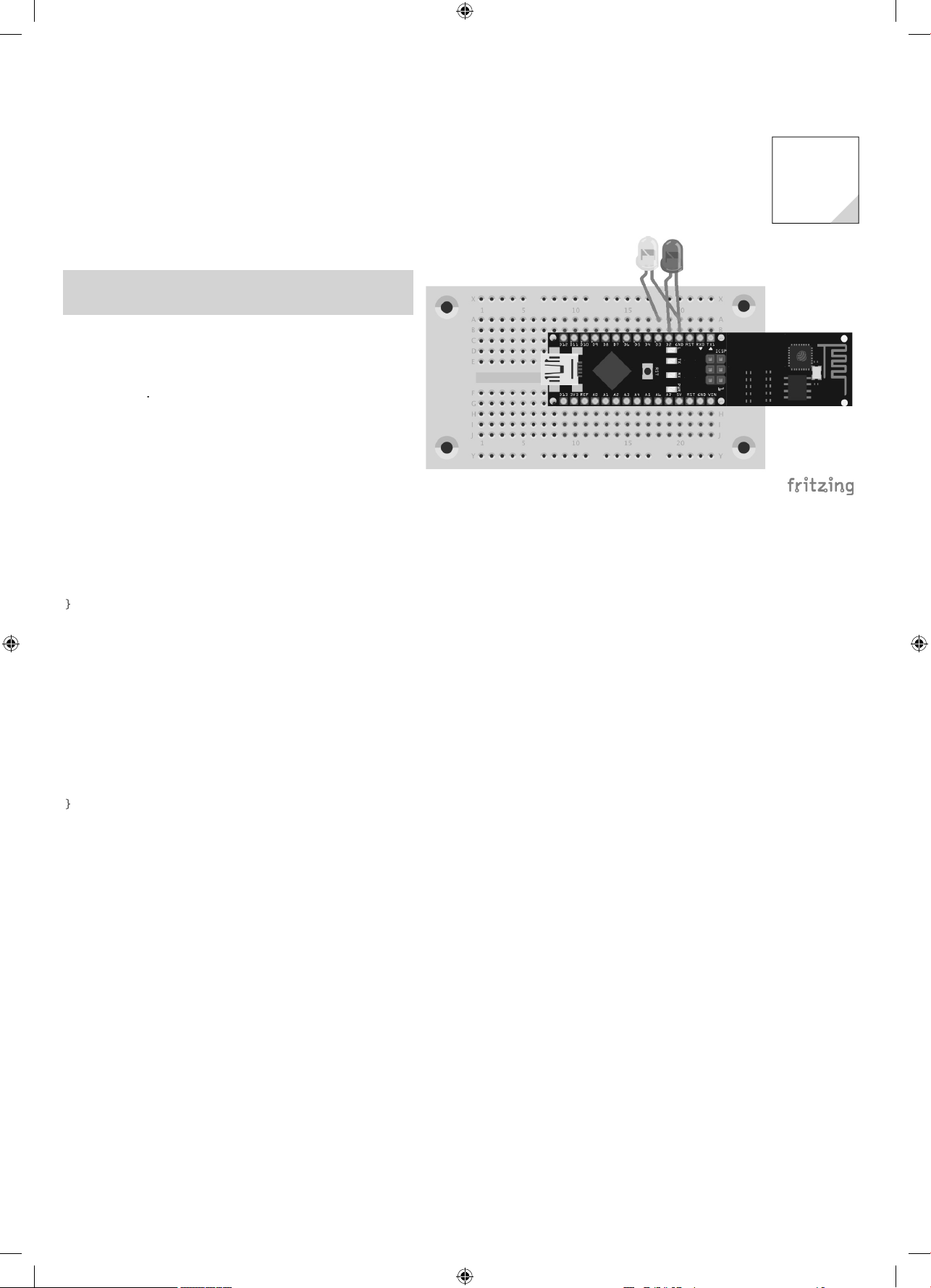
Connection to the IoT-board
To day, you will connect your Smartphone to the IoT-board and
switch the blue LED on and off again with your Smartphone
omponents: 1x board, 1xLED blue with dropping resisto
Installing the App for control
Today, you will not use a dedicated App yet, but control the
board via the free App
erial Bluetooth Terminal from the
pp-Store Google Play
he circuit is similar to the circuit from day 3
The progra
The program for this day is based on the fi rmware for the IoT-board. The program parts needed from the
fi rmware are enclosed in the fi le
Radio connection ready
The fi rmware (and thus also the template) is programmed in such a way that the orange LED
at pin 13 remains lit when the wireless connection is ready. Therefore, wait until this LED lights
up before you connect to the IoT-board
orlage.in
in directory
emplat
6. Da
Copy the fi le Vorlage.ino into a new director
the fi nished fi le Ta
06.in
from the directory
ag06
ag06 ri
ht away. Now open the fi le
fi le Ta
06.ino
You can
ith
rduino IDE. The template contains some functions already. The constant for the internal LED is
present already. The constant L
for the additional LED can be defi ned right below the
internal LED
#defi ne LedPin 1
#defi ne LedPinBlue
the end of the method se
oid setu
digitalWrite(LedPinBlue, HIGH
{
, the LED is switched on
The code for switching the integrated LED at pin 13 on and off is already there. Add the followin
to it
if (Text.startsWith(“Led on”) || Text.startsWith(“LED on”) || Text.startsWith(“LED
ON”
digitalWrite(LedPin, HIGH
digitalWrite(LedPinBlue, HIGH)
if (Text.startsWith(“Led off”) || Text.startsWith(“LED off”) || Text.startsWith(“LED
OFF”
digitalWrite(LedPin, LOW)
digitalWrite(LedPinBlue, LOW)
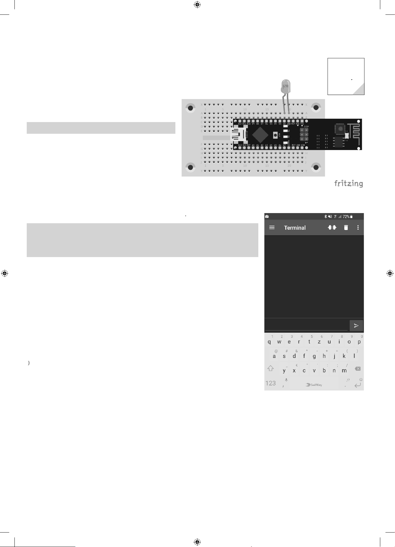
After the fi rst start, you will see an empty black
window
When the
rite(LedPinBlue, HIGH) will
15007-3 Conrad Adventskalender Internet of Things 2017_en.indd 1315007-3 Conrad Adventskalender Internet of Things 2017_en.indd 13 13.08.2017 17:03:0313.08.2017 17:03:03
LED on or L
n
r LED
N
digitalWrite(LedPin, HIGH) an
digital
internal LED and the blue LED on.
Page 14

)
ast
e:
…
{
}
luetooth Devices
l
ection cannot be established the
ected
.
ectio
ust be established twice
shed
and push the arrow icon, the two LEDs will be switched off. Entering
ll
l.
he name of the network is Bluething103 and the password is 1234
board
uetoot
s.
.
if (text.startsWith(“echo”) || text.startsWith(“Echo”)) {
HC05.print(“>> “ + text);
ow you can install the program on the IoT-board. Switch on Bluetooth at your Smartphone and
elect the newly established Bluetooth network. You can see the corresponding name in the serial
onitor of the Arduino IDE. Open the respective window via To ols/Serial monitor. When con-
ecting, you need to enter a password; you can see the password in the serial monitor as well.
hen the IoT-board receives data, the following
oop will be performed:
while(HC05.available() > 0){
…
Text=””;
}
ow enter a call for the function to be programmed
ookRec(Text
while(HC05.available() > 0){
hookRec(Text);
Text=””;
}
before the l
lin
n this function, you can now output the received
ext via the wireless interface:
oid hookRec(String text)
Use the central menu to get to the App settings.
You can also fi nd the network of the IoT-
he list of the Bl
h network
ow start the Bluetooth-App you installed before. After starting, go to the menu (three dashes on
op of each other at the left edge) of the App and select the menu item B
ow select the corresponding network and switch to the terminal by clicking the menu icon once
nd then selecting Termina
n the terminal, click the connection symbol (to the left of the garbage bin). After a short moment,
ou will be asked to enter the password. It is 1234 The conn
rst time; therefore, click the icon again. Now the connection should be established. The terminal
indow will show the message
he conn
n m
nn
Now you can communicate with the IoT-board
s long as you have not entered a password in the Bluetooth-App, you need to establish the
connection twice. The fi rst time, you enter the password. The second time, the connection is
i
.
in
you now enter
onwill switch the LEDs on again. Every input starting echo will be sent to the board, which wi
return the input starting with two arrows. The text is then output on the termina
ed
he Terminal-App is now ready for communication.
echo shows that the App can also receive information
rom the IoT-board
15007-3 Conrad Adventskalender Internet of Things 2017_en.indd 1415007-3 Conrad Adventskalender Internet of Things 2017_en.indd 14 13.08.2017 17:03:0413.08.2017 17:03:04
Page 15

7th Da
y
t
-
)
m
o
7
;
;
;
{
);
;
;
);
;
;
);
;
s
;
;
g
p
used to
.
5
In the Advent calendar today
•1x potentiometer, 15kOhm
Controllable running ligh
To day’s project is a running light the speed of which can be
controlled with a potentiometer.
omponents: 1x board, 1xLED green with dropping resi
stor, 1xLED yellow with dropping resistor, 1xLED red with
dropping resistor, 1x15-kOhm-potentiometer, 4x jumper
(different lengths
The progra
The program for this day is called
irectory
nt analogPin = A5
nt analogValue
nt led1 = 8;
nt led2 = 6
nt led3 = 4;
oid setup()
pinMode(analogPin, INPUT
ag0
ag07.in
and located in
7. Day
The potentiometer takes up some space. Therefore, the IoT-board must be pushed up higher
than on the day before. LEDs from the left to the right: green, yellow and red
pinMode(led1, OUTPUT)
pinMode(led2, OUTPUT);
pinMode(led3, OUTPUT);
digitalWrite(led1, LOW);
digitalWrite(led2, LOW);
digitalWrite(led3, LOW);
Serial.begin(9600);
oid loop() {
analogValue = analogRead(analogPin);
Serial.println(analogValue)
delay(analogValue
digitalWrite(led3, LOW);
digitalWrite(led1, HIGH)
delay(analogValue)
digitalWrite(led1, LOW);
digitalWrite(led2, HIGH
delay(analogValue)
digitalWrite(led2, LOW);
digitalWrite(led3, HIGH);
How the program work
analogValue = analogRead(analogPin);
delay(analogValue)
digitalWrite(led3, LOW);
digitalWrite(led1, HIGH)
The temporary variable analo
wait and then switch the LEDs.
15007-3 Conrad Adventskalender Internet of Things 2017_en.indd 1515007-3 Conrad Adventskalender Internet of Things 2017_en.indd 15 13.08.2017 17:03:0513.08.2017 17:03:05
Pin is used to read the value set for the
otentiometer. delayis
Page 16

1
6
y
y
o
p
.
pps
butto
.
m
.
y
8th Da
8. Da
In the Advent calendar toda
•1x piez
Outputting sounds through the Ap
An App can be used to output sounds on a piezo.
omponents: 1x board, 1xpiezo
The two wires of the piezo are connected to D2 and GND. The rest is solved via the software
Development environment for the A
The IoT-board in this Advent calendar is controlled using the Serial Bluetooth Terminal App that has
been used before, and the self-developed Smartphone-Apps for the Android operating system6. The fi nished project fi les can be downloaded at
is MIT App Inventor 2 (http://appinventor.mit.edu
he development environment runs in the browser. Therefore, you need internet access during development.
lick the
with Google
Setting up an account with Google
you have no Google account yet, set up an account for development with the
AI2) via
n Create apps! to start the development environment. Using them requires a free account
ttps://accounts.google.co
ttp://www.buch.cd each. The development environment used
.
Inventor 2
After successful login, you will get to the dashboard. Here, you will see all Apps developed so far. Since
you have probably never developed an App with AI2 before, you will see an empty dashboard.
6The chipset integrated on the IoT-board is supported only by Android-Smartphones
15007-3 Conrad Adventskalender Internet of Things 2017_en.indd 1615007-3 Conrad Adventskalender Internet of Things 2017_en.indd 16 13.08.2017 17:03:0513.08.2017 17:03:05
Page 17

The interface is not yet available in German
.
.
2
the start butto
and enter the name
In order to test your self-developed App during development, you
need to install the free App MIT AI2 Companion from the Google
Play Store on your Smartphone. After starting, you need to enter the
code for your App; for this, you need to create an App fi rst
Your fi rst App with AI
Now click
eine_erste_App. Note that the name must not contain any spaces.
The development environment will open in your browser now.
n
uring development, do not
tart the App directly but take
the detour through the MIT App
nventor 2 Companion. This way,
you do not need to install the
pp on the device manually.
After starting, the App interface will still be empty.
15007-3 Conrad Adventskalender Internet of Things 2017_en.indd 1715007-3 Conrad Adventskalender Internet of Things 2017_en.indd 17 13.08.2017 17:03:0613.08.2017 17:03:06
Page 18

1
8
-
.
to
and
to
y
p
ouc
t
touched
ut-n1
.
tabs
.
The window is broken up into several areas. On the left, you
can see the interface elements available for the App in the area
Pallet. Next to it, you can see the interface of your App in the
Viewer . Components
and Properties the properties of the currently selected compo
nent
Now draw text in the form of a label into the window. Adjust
the label by settingidth
nter:I Now the label is centred horizontally. Next, change the
font size toFontSize 30 and change the text (fi eld:
fi rst Ap
Now the App is to be expanded by an interaction. For this, enter
ns from the window
T
h me via the
x
: not
hows the components used in your App
xt to M
omponents and change the label to
roperties. Below this, insert a label with the
You can change components in the window
at once then.
the
esigner and
locks to get to the two views of the development environment
roperties. The display in the Viewer will change
App-interface with the three components
AI2 has two views for an App: the view for design of the interface, called the Designer (tab
esigner,
and the view for programming in block language (tab Blocks). These two tables are displayed in the
upper area of the development environment.
Clicking Blocks will open the view of the block programming language. Now select the component B
within theBlocks area; you will see the available results to which you can react in the App
Now select the two blocks when Button1.TouchDown andwhen Button1.TouchUp
In both cases, the
content of the label Label2 is to be adjusted. For this, click Label2 and select the element set Label2.
15007-3 Conrad Adventskalender Internet of Things 2017_en.indd 1815007-3 Conrad Adventskalender Internet of Things 2017_en.indd 18 13.08.2017 17:03:0713.08.2017 17:03:07
Page 19

ext to. Either insert the element twice or insert the element
.
utto
ouchDo
utton1.
t
(top-most element).
.
case of
utto
ouchDo
to
ouched
utto
ou-
touched
ll
ect
Code
.
-
once and copy it via the context menu (right mouse button) of
the component
Components have a context menu. Use Duplicate
to copy the selected component.
Now insert the two components within the previously inserted
elements (when B
n1.T
wn
ndwhen B
ouchUp. Now you still need text content. For this, select the
empty element from the category
x
The element with the two quotation marks is used for changing the label
In
chUp, the text is set to
when B
: T
n1.T
. For when B
: Not
wn, the text is
n1.T
Now you can test the app on your Smartphone.
For this, select Connect/AI Companion in the
menu. Now a text code and a QR-code wi
appear. Enter either the code in the
Companion or scan the QR-Code with scan QR
. Start the App with
nn
with
Now the App opens on your Smartphone. When
ou touch the button, the text will change
For programming the logic, you can go to the selection via categories (Built-in
ponents (creen1
.
or via the com
15007-3 Conrad Adventskalender Internet of Things 2017_en.indd 1915007-3 Conrad Adventskalender Internet of Things 2017_en.indd 19 13.08.2017 17:03:0713.08.2017 17:03:07
he text of the label is adjusted when the button is touched.
his is how simple App development with AI2 is.
Page 20

ontrolling the piezo with the Ap
p
g
o
8
-
}
i
ia
.
ection area
ea
-
t
(e.g.
.
-
e
uetoothClient
from the category
-
E
.
n order to control the IoT-board with an App, you need a Sketch on the board that reacts
to the commands from the App and an App. Today, we want to control the enclosed piezo
with an App. The Sketch you need for this is Ta
Sketch onto the IoT-board.
The Sketch is based on the already-used fi le Vorlage.ino. The principle of all Sketches in
this Advent calendar that react to the App is as follows: A text is sent through the wireless
nterface, which is evaluated in the Sketch, followed by execution of an action. It works
the same way in the other direction: The App will receive a text from the IoT-board via the
wireless interface, evaluate the text and then perform a corresponding action. The com
and to play a sound is Sound:
if (Text.startsWith(“Sound”) || Text.startsWith(“SOUND”) || Text.
tartsWith(“sound”)){
playMelody();
08.in
in the directory
ag0
Load this
he upper area of the App shows whether the Bluetooth
connection has been established or not
The left fi gure shows the individual areas of the App. The connection area includes
ung andontainer_MAC. The actual App, which changes from project to project, is located in the
ontainer_App This container contains the function area (uttonTon
Container_App_Info
What is a container?
You can place your elements using various layout managers in the categoryLayou
angement); these help you with horizontal and vertical placement. The elements are placed within
this kind of layout manager. Since these layout managers usually contain several elements, they are
alled containers (layout containers)
The associated App is contained in fi le p
ezo.a
. Import the fi le into AI2
mporting projects into AI2
All Apps are provided as aia-fi les ready for use in the download archive. In order to
open a fi le in AI2, you must import the project fi le via the menu item
rojects/Import
project (.aia) from my computer ...
Function of the App
The following Apps that were created with AI2 are built based on a template; therefore,
this App is now described precisely and referred to in the further course. The App is made
of four areas in total:
•Conn
•Function ar
•App info area
•Internal, invisible area
ontainer_Verbin
and the App information area
.
HorizontalAr-
All components contained in the App
in a hierarchy overview. The most
important components have been given
indicative names.
15007-3 Conrad Adventskalender Internet of Things 2017_en.indd 2015007-3 Conrad Adventskalender Internet of Things 2017_en.indd 20 13.08.2017 17:03:0813.08.2017 17:03:08
hanging component names
you add components to an interface in the AI2, the component swill receive an automatically gene
ated name. In contrast to the other properties of a component, you cannot change names in the win-
w Properties but need to use the area
omponent and click the button
nam
omponents for this. Here, you can select the corresponding
The interface contains three invisible components in total. For use of Bluetooth, you need the component
Bl
onnectivity The component is only pulled into the interface area
and does not require any further confi guration. To select the corresponding Bluetooth device, the compo
nentActivityStarter (in the upper screen
is assigned the value
ndroid.Bluetooth.adapter.action.REQUEST_ENABL
continuous verifi cation of the wireless connection, the element
ensors is used. The
imerInterval is set to
enn_BT_An
from Connectivity is needed. The ActivityStarter
in window Properties
in the window Properties For
lock (in the upper fi gure
imer
from
Page 21

Programming takes place within the
.
pp.
ectio
tse
established
g
the block
buttonTon.Click
uend
uetooth.SendText
s is the
locks
k
.
address of the available devices
d.
ection to the selected device is established
tab Blocks. The Timer sets the connection status. The property
nnec-
tedcan be used to check if the App is
connected to a Bluetooth device
When clicking the button
onnect, the
list of available Bluetooth devices will
be displayed. If the list is empty, you
need to go back into the App, where
ou will automatically be asked for
the access rights for the Bluetooth
There will be a regular check of whether the wireless connection is active or not
interface. Enter the password 1234.
When clicking the button again, the
list should now be displayed.
Here, an entry named Bluethingshould appear as well. After clicking the entry, you need to enter
the password
234 to connect the App to the board. This list is displayed via the Block
hen
erbinde.BeforePicking. As you can see by the following block, the button has two functions:
Connecting and disconnecting.
The name and MAC-
re displaye
The button initiates the Bluetooth connection between the board and the A
The conn
n i
lf is
in the block when Verbinde.AfterPickin
The three upper blocks will appear in all Apps in this Advent
calendar. The actual function in today’s App is implemented
in
val
the wireless interface using the block
n
. In this function, only the
is submitted, completed by a n A text is sent via
ll Bl
.
Submit the text as parameter. Do not forget to defi ne an end
criterion. In this example, the end criterion is
n. Thi
sign that the Sketch reacts to.
The conn
Copying blocks to other projects
The areaB
contains a backpack icon. You can use it to copy blocks from
the block editor from one project into another. Simply pull the corresponding
ocks into the backpack; you can then reuse these blocks in other projects. In
order to empty the backpack again, right-click the work area and select
mpty
Backpac
.
Strings can be connected to each other with the componentjoin
15007-3 Conrad Adventskalender Internet of Things 2017_en.indd 2115007-3 Conrad Adventskalender Internet of Things 2017_en.indd 21 13.08.2017 17:03:0913.08.2017 17:03:09
Page 22

esting the App
ouc
ect
ow start the App via
ndroid-Smartphone. Scan the QR-Code or enter the code and start the App via connect with
ode
The App now starts.
T
h
nn
. Now you can connect to the IoT-board.
onnect/AI Companion and call the AppMIT AI2 Companion on your
he connection is not active yet at fi rst.
The App is now connected to the IoT-board.
If you touch Play sound now, the IoT-board will play a melody via the piezo.
15007-3 Conrad Adventskalender Internet of Things 2017_en.indd 2215007-3 Conrad Adventskalender Internet of Things 2017_en.indd 22 13.08.2017 17:03:0913.08.2017 17:03:09
Page 23

9th Da
y
s
.
e.RG
dua
efore also need three
p
r
.
etch for the IoT-board
o
etc
eacts to four but
;
;
();
{
;
}
In the Advent calendar today
•1x RGB-LED with dropping resistor
RGB-LED
normal LED is always lit in only one colour. The RGB-LEDs used in the
dvent calendar can be lit in different colours. Generally, three LEDs
with different colours are installed in a transparent housing here. Each
of these three LEDs has its own anode, through which it is connected to
a GPIO pin. The cathode, which is connected to the ground line, is only
present once. Therefore, an RGB-LED has four connection wires
The connection wires of the RGB-LEDs have different lengths to identify
them clearly. In contrast to regular LEDs, the cathode is the longest wire
r
B-LEDs work like three indivi
l LEDs and ther
220-Ohm dropping resistors (red-red-brown). The RGB-LEDs in this Advent
calendar have them already installed.
Changing the colour of an RGB-LED with the Ap
Today, you will program an App to change the colour of an RGB-LED.
Components: 1x board, 1xRGB-LED with dropping resistor, 1xjumpe
9. Day
Connection pins of an RGB-LED
Circuit diagram for an RGB-LED with 3 dropping resistors
The RGB-LED also already has its dropping resistors integrated. The second leg (short leg) is the
cathode and must be connected to the ground
The Sk
The program for this day is called
ns:
if (Text.startsWith(“Red”) || Text.startsWith(“RED”) || Text.startsWith(“red”)){
rot()
} else if (Text.startsWith(“Blue”) || Text.startsWith(“BLUE”) || Text.startsWith(“blue”)){
blau()
} else if (Text.startsWith(“Green”) || Text.startsWith(“GREEN”) || Text.startsWith(“green”)){
gruen
} else if (Text.startsWith(“Off”) || Text.startsWith(“OFF”) || Text.startsWith(“off”))
aus()
ag9.in
and located in directory Tag9 The Sk
h r
-
15007-3 Conrad Adventskalender Internet of Things 2017_en.indd 2315007-3 Conrad Adventskalender Internet of Things 2017_en.indd 23 13.08.2017 17:03:1013.08.2017 17:03:10
Page 24

Each colour has its own function within the Sketch. Below, the function rot() is presented:
{
;
);
;
pp
.
d
t.
.
oid rot()
Serial.println(„Red“)
analogWrite(redPin, HIGH
analogWrite(greenPin, LOW);
analogWrite(bluePin, LOW)
The A
he associated App is contained in fi le RGB.aia. Import the fi le into AI2
Depending on the buttons pushed, a corresponding text is sent via the Bluetooth interface:
, red\n is sent, for blue,
For re
off, off\n
sen
lue\n is sent, for green, green\n
s sent and for switching
he LED is switched via four buttons
he blocks in the AI2
15007-3 Conrad Adventskalender Internet of Things 2017_en.indd 2415007-3 Conrad Adventskalender Internet of Things 2017_en.indd 24 13.08.2017 17:03:1113.08.2017 17:03:11
Page 25

10th Da
y
n
n
d.
-
V
.
Sketch
o
0
l-
p()
{
();
}
{
{
;
}
}
}
);
{
d
d
.
-
.
5
In the Advent calendar today
•1x butto
Displaying the push of a butto
To day, your IoT-board will react to a mechanical push of a button and send a message to the wireless interface.
omponents: 1x board, 1xbutton, 1xpotentiometer,
5xjumpers (different lengths)
Digital pins can not only output data, e.g. via LEDs, but also be
used to enter data. We use a button for input in today’s project
that is directly connected to the board. The button has four
connection pins, with two opposite ones (large distance) being
connected to each other from case to case. While the button
is pushed, all four connections are connected to each other. In
contrast to a switch, a button will not latch. The connections
are broken at once when the button is release
When a +5-V-signal is pending on a digital input, this is evaluated as logically
If the button were open, the input would not have any clearly defi ned condition. When a program
requests this pin, there may be random results. In order to prevent this, a comparatively very high resis
tor is connected to the ground. This pull-down-resistor pulls the status of the input pin back down to 0
when the button is open. Since the resistance is very high, there is no danger of short circuit while the
utton is pushed either. When the button is pushed, +5V and the ground line are connected directly via
this resistor
he IoT-board is very long; therefore, the button must be placed crosswise on the board, and
e jumpers must be partially placed below the connected USB cable
rue
0. Day
The
The program for this day is called
uate whether the button has been pushed:
oid loo
int reading = digitalRead(buttonPin);
if (reading != lastButtonState)
lastDebounceTime = millis
if ((millis() – lastDebounceTime) > debounceDelay) {
if (reading != buttonState)
buttonState = reading;
if (buttonState == HIGH)
ledState = !ledState
digitalWrite(LedPin, ledState
{
If the button was been pushed, a message will be sent through the wireless interface:
if (reading != lastButtonState)
HC05.print(“Button pushed\n”);
ag10.in
and located in directory
ag1
igitalReadis called to eva
Displaying the reaction of the IoT-boar
The App Serial Bluetooth Terminal that has been used before is used for displaying the push of
the button on the Smartphone. After connecting to the IoT-board, the message Button pushe
will be displayed when the button is pushed.
15007-3 Conrad Adventskalender Internet of Things 2017_en.indd 2515007-3 Conrad Adventskalender Internet of Things 2017_en.indd 25 13.08.2017 17:03:1113.08.2017 17:03:11
Messages received are written in the terminal win
dow in green
Page 26

11th Da
y
y
e
p
h
o
-
p
t
button that is already familiar:
s
b-
uetoot
butto
ues
touched
.
.
y
11. Da
In the Advent calendar toda
•1x switching wir
he integrated dropping resistors make the circuit very compact. LEDs from the left to the
right: red and green.
ED echo by Ap
oday’s project is an LED echo. Set a sequence with two
interfaces in the App. The LEDs on the board will fl ash in this
equence.
omponents: 1x board, 1xLED red with dropping resistor,
xLED green with dropping resistor, 1xjumper
e Sketc
he program for this day is
ag11
The App determines the echo sequence. The text is out
put in the following form: RNNGNN. R means red and G means
green, e.g. R5G3 – this would mean having the red LED fl ash
ve times and then the green LED three times:
if (Text.indexOf(“R”) != -1 && Text.indexOf(“G”) !=
1) {
setzeFarbe(Text);
else if (Text.startsWith(“Off”) || Text.
tartsWith(“OFF”) || Text.startsWith(“off”)){
aus();
ag11.in
and located in directory
e Ap
The App has four buttons in addition to the
reen ubmit values andReset value
When touching Red or
reen the respective label is increased by one. Reset values resets
the two values to 0. Submit values submits the values to the IoT-board. The value to be su
mitted is put in interim storage in a global variable. The content of the variables is transmit-
via Bl
ach button has a separate when.Click-query
h when the
n
mit val
onnec
is
Red
.
he App uses the App already familiar from day 8
15007-3 Conrad Adventskalender Internet of Things 2017_en.indd 2615007-3 Conrad Adventskalender Internet of Things 2017_en.indd 26 13.08.2017 17:03:1213.08.2017 17:03:12
Page 27

12th Da
y
r
p
.
r
h
2
500ms and that there
500ms break before
:
{
;
);
;
p
.
luetooth Devices
In the Advent calendar today
•1x LED orange with dropping resisto
Setting the running light speed by Ap
In today’s project, you will control the speed of a running light
with the App
omponents: 1x board, 1xLED red with dropping resistor,
1xLED orange with dropping resistor, 1xLED green with
dropping resistor, 1xjumpe
The Sketc
The program for this day is Tag12.ino and located in directory
ag1
To control the running light, you need two parameters:
The waiting time while another LED is lit and the number of
passes. These values are sent by the App in a string in the form
wTTTdNN. For example, w500d4 means that each LED will be
lit for
will be a
activating another LED. This running light would go through the sequence four times
if (Text.indexOf(“w”) != -1 && Text.indexOf(“d”) != -1)
String temp = Text.substring(Text.indexOf(“w”)+1,Text.indexOf(“d”));
int wartezeit = temp.toInt()
temp = Text.substring(Text.indexOf(“d”)+1
int durchlaeufe = temp.toInt();
laufl icht(wartezeit, durchlaeufe)
unning light with three LEDS: red, orange and green.
12. Day
The Ap
The values are submitted using the App
send the command directly to the IoT-board in the form as described
erial Bluetooth Terminal After connecting, you can
The output shows that two connection attempts are
needed for successfully connecting to the IoT-board.
If the connection does not work, check the menu
m B
the right device.
to see that you have chosen
15007-3 Conrad Adventskalender Internet of Things 2017_en.indd 2715007-3 Conrad Adventskalender Internet of Things 2017_en.indd 27 13.08.2017 17:03:1313.08.2017 17:03:13
Page 28

13th Day
y
r
p
y.
h
3
-
board
set
od
be
g
ust be sent:
{
();
}
””;
ing
d
ues are the
tte
a
e
{
{
();
;
{
{
;
13. Day
In the Advent calendar toda
•1x LED pink with dropping resisto
e pink LED is used to signal that the connection is active.
while(HC05.available() > 0){
Zeichen = HC05.read();
Text.concat(Zeichen);
if (Zeichen == ‚\n‘) {
if (Text.indexOf(“R”) != -1 && Text.indexOf(“G”) && Text.indexOf(“B”) )
setzeFarbe(Text);
} else if (Text.startsWith(“Off”) || Text.startsWith(“OFF”) || Text.startsWith(“off”))
djusting RGB via a slider in the Ap
In addition to displaying basic colours, an RGB-LED can also
isplay graduations. You can use an App to set the colour of
the RGB-LED precisel
omponents: 1x board, 1xRGB-LED with dropping resistor,
1xLED pink with dropping resistor, 1xjumper
e Sketc
The program for this day is Tag13.ino and located in directory
ag1
. The RGB-LED is controlled via a string in the form RNN
GNNNBNNN. Only when a string in this form is received by
he IoT-
To switch off the LED, the strin
will the colour be
via the meth
ff m
zeFar
.
aus
Text=
In the function setzeFarbe the submitted text is broken down into parts with the substr
he val
void setzeFarbe(String text) {
if (text.indexOf(“R”) != -1 && text.indexOf(“G”) && text.indexOf(“B”) )
String temp = text.substring(text.indexOf(“R”)+1,text.indexOf(“G”));
if (temp.indexOf(“.”) != -1)
temp = temp.substring(0, temp.indexOf(“.”));
}
int rot = temp.toInt
temp = text.substring(text.indexOf(“G”)+1,text.indexOf(“B”))
if (temp.indexOf(“.”) != -1)
temp = temp.substring(0, temp.indexOf(“.”));
}
int gruen = temp.toInt();
temp = text.substring(text.indexOf(“B”)+1);
if (temp.indexOf(“.”) != -1)
temp = temp.substring(0, temp.indexOf(“.”));
}
int blau = temp.toInt();
analogWrite(redPin,rot)
analogWrite(greenPin,gruen);
analogWrite(bluePin, blau);
}
}
n wri
n vi
nalogWrit
method an
15007-3 Conrad Adventskalender Internet of Things 2017_en.indd 2815007-3 Conrad Adventskalender Internet of Things 2017_en.indd 28 13.08.2017 17:03:1313.08.2017 17:03:13
Page 29

The Ap
p
_
a
.
luetooth.SendText
.
d.
abels has been set to 15%
The development environment for today’s App is the AI2. For this, import the fi le RGB
ider.ai
send the value of the three sliders to the IoT-board
Use three sliders to set the value for the respective colour. Push Set colour to
Touching
rbeB
The string is composed viajoin, which can also be neste
et colour will cause the text to be submitted to be composed in the variable
sends the text via the wireless interface
ach slider is combined with a label in a HorizontalArran-
ement
To place all sliders on top of each other, the width
the three l
.
15007-3 Conrad Adventskalender Internet of Things 2017_en.indd 2915007-3 Conrad Adventskalender Internet of Things 2017_en.indd 29 13.08.2017 17:03:1413.08.2017 17:03:14
Page 30

14th Da
y
y
d
t
.
-
)
k:
h
d
.
g
g
.
h
i
4
l
d
ess
face
t
{
);
{
);
}
.
d
14. Day
In the Advent calendar toda
•1x modelling clay re
•1x resistor 20MOhm
he end of the two protruding jumpers goes into a piece of modelling clay each. Best shape it
into a small, round ball. The modelling clay contact at A3 is used as the input
odelling clay contac
oday, you will use the enclosed modelling clay as an input
and change the background colour of an area in the App when
he modelling clay is touched
omponents: 1x board, 2xpieces of modelling clay, 1xresi
tor 20MOhm, 3xjumper (different lengths
is is how sensor contacts wor
e pin switched as input is connected to +3.3V via an
extremely high-Ohmic resistance (20MOhm), so that a weak
ignal that is still clearly defi ned as high is pending. A person
who is not fl oating freely in the air is always grounded and
upplies a low level through electrically conductive skin. When
is person touches a sensor contact, the weak high signal is
overlaid by the much higher low level of the fi ngertip, pulling
e pin to low level.
he actual height of the resistance between hand and ground
depends on many things, including shoes and fl oor. Barefoot
in wet grass offers the best ground connection, but stone fl oors
usually work well, too. Wood fl oors insulate more strongly, and
plastic fl oorings often even are positively charged. For the circuit to
ork at all times, an additional ground contact is installed in eac
circuit, similarly to sensor buttons at elevators and doors. When
it and the actual sensor are touched at the same time, the groun
connection is made in any case
Circuit diagram for sensor contacts on the IoT-boar
is much easier to grasp than a simple piece of wire. The area on which the hand touches the contact is
much larger. Thus, a “loose contact” is less likely to occur. Cut a piece of about 10cm from the switchin
wire, remove the insulation for about 1cm on either end and push one end into a piece of modellin
clay. Push the other end into the board as illustrated
The IoT-board has analogue inputs that are very suitable for sensor contacts. Analogue inputs supply
values between 0 (low level) and 1023 (high level): Values between 100 and 200 are good limits to tell
apart contacted and non-contacted sensor contacts.
The Sketc
The program for this day is Tag14.
can be programmed with a few lines. ana
will be sent via the wirel
void loop()
sensorValue = analogRead(sensorPin
if (sensorValue < 256)
HC05.print(“LOW\n”
delay(1000);
inter
Putty conducts current about as well as the human skin does. It
can easily be formed in any desired shape, and a putty contact
no
nd located in directory
ogRea
reads in the value; if it is below the threshold, a text
with
C05.prin
ag1
. The actual function in this sketch
15007-3 Conrad Adventskalender Internet of Things 2017_en.indd 3015007-3 Conrad Adventskalender Internet of Things 2017_en.indd 30 13.08.2017 17:03:1413.08.2017 17:03:14
Page 31

The Ap
p
_
a
.
.
.
.
.
t
.
d
.
Today’s App Knete
fi rst
To check if a text has been sent via the Bluetooth interface, it must be periodically reviewed
whether a text is present. This is done with the existing timer
Confi guring blocks
The elements in the area Blocks in the block editor can partially be confi gured. The confi guration takes place using the blue cogwheel at the component.
The if-block also supports else and else-if
Then click the element you want to use. The component will change
Schalter.ai
contains a label that has an orange background colour at
1
The timer has only been used to display the status of the wireless connection so far
luetooth.ReceiveTex
is used to read
the text from the wireless interface
o make the coloured label well visible, its width an
eight have been set to 30 pixels.
You can select the colour to be set in a selection fi eld
15007-3 Conrad Adventskalender Internet of Things 2017_en.indd 3115007-3 Conrad Adventskalender Internet of Things 2017_en.indd 31 13.08.2017 17:03:1513.08.2017 17:03:15
Page 32

15th Da
y
y
)
h
5
a
d
-
p
t
sfers the command to
ess
face
{
);
;
{
}
{
}
{
;
}
pp
uetoot
;
.
.
.
15. Day
In the Advent calendar toda
•1x resistor 20MOhm
he ends of the three protruding jumpers go into a piece of modelling clay each. You need two
igh-Ohmic resistors due to the two modelling clay contacts
ifferentiable modelling clay contacts
Now use two modelling clay contacts and display in the App
which contact has been pressed.
omponents: 1x board, 3xpieces of modelling clay,
xresistor 20MOhm, 4xjumper (different lengths
e Sketc
The program for this day is Tag15.ino and located in directory
ag1
. As on day 14, activation of the modelling clay contact is
vi
analogRea
elling clay contact. HC05.
he wirel
void loop()
sensorValue1 = analogRead(sensorPin1
sensorValue2 = analogRead(sensorPin2)
if (sensorValue1 < 256)
HC05.print(„Kontakt 1\n“);
if (sensorValue2 < 256)
HC05.print(„Kontakt 2\n“);
if (sensorValue1 < 256 || sensorValue2 < 256)
delay(1000)
inter
There is a separate variable for each mod
rin
then tran
.
Activating a modelling clay contact causes the
programmed output in the terminal
he A
he texts are displayed using the App
he texts should appear once you touch a modelling clay contact
rial Bl
h Terminal. First, connect to the IoT-board
15007-3 Conrad Adventskalender Internet of Things 2017_en.indd 3215007-3 Conrad Adventskalender Internet of Things 2017_en.indd 32 13.08.2017 17:03:1513.08.2017 17:03:15
Page 33

16th Da
y
r
p
button.
g
r
h
6
etc
eacts to
d
ess
;
.
{
;
O
or
GH
igi
e
);
}
;
pp
a
luetooth.SendText
.
.
above the two buttons (on
.
In the Advent calendar today
•1x fl ashing LED red with dropping resisto
Controlling the fl ashing LED with the Ap
Switch the fl ashing LED on with a button and off again with
nother
omponents: 1x board, 1xfl ashing LED red with droppin
resisto
The Sketc
The program for this day is Tag16.ino and located in directory
ag1
. The Sk
if (Text.startsWith(“On”) || Text.startsWith(“ON”)
|| Text.startsWith(“on”)){
an()
else if (Text.startsWith(“Off”) || Text
startsWith(“OFF”) || Text.startsWith(“off”))
aus()
The fl ashing LED is switched in two separate functions. Only the value L
via d
talWrit
h r
On
n
Off
rom the wirel
inter-
he fl ashing LED also has a dropping resistor and therefore does not need any further elements
or the circuit
16. Day
W
I
is written
void an() {
Serial.println(„An“);
digitalWrite(blinkPin, HIGH
void aus() {
Serial.println(„Aus“);
digitalWrite(blinkPin, LOW)
}
The A
The App
The already-familiar method
inker.ai
has two buttons for switching the fl ashing LED on and off.
B
is used for sending.
There is a
and off) as a positioning element
Remember that you need to attach the end criterion to the string when sending
15007-3 Conrad Adventskalender Internet of Things 2017_en.indd 3315007-3 Conrad Adventskalender Internet of Things 2017_en.indd 33 13.08.2017 17:03:1613.08.2017 17:03:16
Page 34

17th Da
y
y
.
-
h
7
d
e
set to
;
h
d
:
{
);
);
);
p
uetoot
.
y
.
17. Da
In the Advent calendar toda
•1x potentiometer
A potentiometer is just an analogue sensor from the program’s point of view
nt sensorPin = A5
nt sensorValue = 0;
In the method
oop, t
program will wait for 2000ms before reading the value again
e value is read in via
isplay of the resistor value
Today, you will measure the value of a potentiometer via an
analogue input and can output the value in an App
omponents: 1x board, 1xpotentiometer 15kOhm, 4xjum
per (different lengths)
e Sketc
The program for this day is Tag17.ino and located in directory
ag1
. First, the two variables sensorPin an
defi ned. The potentiometer is connected to the analogue input
5, and therefore, sensorPin is
nalogRea
and passed on to the wireless interface. Then the
5
sensorValu
are
void loop()
sensorValue = analogRead(sensorPin
HC05.print(“value potentiometers = “
HC05.println(sensorValue);
delay(2000
The Ap
The texts are displayed using the App
see the potentiometer value then
rial Bl
h Terminal. First, connect to the IoT-board. You will
15007-3 Conrad Adventskalender Internet of Things 2017_en.indd 3415007-3 Conrad Adventskalender Internet of Things 2017_en.indd 34 13.08.2017 17:03:1713.08.2017 17:03:17
Page 35

18th Da
y
t
g
.
h
8
etc
eacts to the text
p
set numbe
p
off
{
();
;
} el
{
}
pp
.
luetooth.SendText
t
p
ess
face.
.
.
-
y
5
In the Advent calendar today
•1x jumper cable
RGB-running ligh
This App controls the fl ashing duration of an RGB-LED. The LED
will fl ash in alternating colours. You can also stop its fl ashin
again
omponents: 1x board, 1xRGB-LED with dropping resistor,
1xjumper cable
The Sketc
The program for this day is Tag18.ino and located in directory
ag1
The Sk
o
will switch off the RGB-LED. If a number is received, it
will be used as the waiting time between switching one of the
hree LEDs of the RGB-LED on or
if (Zeichen == ‚\n‘) {
Serial.println(Text);
if (Text.startsWith(“stop”))
aus
blinkDauer = 0
se
blinkDauer = leseBlinkdauer(Text);
h r
o
:
and to a
r.
18. Da
The integrated dropping resistors make the circuit very compact
The A
The App RGB_Laufl icht.aia has a slider and two buttons for switching the fl ash on and off
The command B
x
sto
via the wirel
The waiting time is not separately coded but only the value of the slider is sent, followed by a fi nal
n
inter
that is already familiar sends the waiting time or the
The minimum value of the slider is 0 and its maximum value
is 2000. The values represent the waiting time in millisec
onds.
15007-3 Conrad Adventskalender Internet of Things 2017_en.indd 3515007-3 Conrad Adventskalender Internet of Things 2017_en.indd 35 13.08.2017 17:03:1713.08.2017 17:03:17
Page 36

19th Da
y
y
e
.
h
9
D
;
;
;
Sketch reacts to the commands
o
d
eth-
:
{
p
a
.
t
to establish the connec-
y
19. Da
In the Advent calendar toda
•1x jumper cabl
he RGB-LED doesn’t need any dropping resistors here either. Use the jumper cable to connect
o the ground.
pp to select hardware Apps
Today, we will combine two functions in one circuit: Playing a
sound with the piezo and fl ashing of an RGB-LED. Use the App
to select the corresponding function
omponents: 1x board, 1xRGB-LED with dropping resistor,
1xpiezo, 1xjumper cable
e Sketc
The program for this day is Tag19.ino and located in directory
ag1
. First, you need to defi ne the proper pins as variables:
//---- Pins of the RGB-LE
nt redPin = 9;
nt greenPin = 7
nt bluePin = 8
---- Pin Piezo
nt piezo = 3
The
ods have been taken from the previous Sketches
iez
an
. The m
his App uses the already-familiar elements from the other
Apps for connecting. Use Connec
on.
if (Text.startsWith(“piezo”)){
aus();
playMelody();
} else if (Text.startsWith(“rgb”))
blinken(500);
};
The Ap
e App
pp_Wechsler.ai
he function is mapped in two when.Click blocks. Only the text to be sent is adjusted.
The blocks are very similar. In such cases, watch that you select the right
button in the when.Click block.
has two buttons to switch between the piezo and RGB
15007-3 Conrad Adventskalender Internet of Things 2017_en.indd 3615007-3 Conrad Adventskalender Internet of Things 2017_en.indd 36 13.08.2017 17:03:1813.08.2017 17:03:18
Page 37

20th Da
y
C
.
)
h
ocated
ec-
0
g
d
:
;
p
uetoot
-
e.
.
-
In the Advent calendar today
•1x NT
Heat sensor in the App
To day’s project uses an NTC for temperature measuring. You
can test this project well, e.g. by approaching a candle on the
dvent wreath with the NTC
omponents: 1x board, 1xNTC, 1 x potentiometer
15kOhm, 6xjumper (different lengths
The Sketc
The program for this day is Tag20.ino and l
tory
ag2
. The Sketch is set up very simply. After callin
analogRea
the value will be sent to the App by Bluetooth;
then there will be a pause of 2 seconds and the value will be
read again and sent
oid loop() {
sensorValue = analogRead(sensorPin);
HC05.print(“Value of the NTC = “)
HC05.println(sensorValue);
delay(2000);
in dir
0. Day
Do not forget to use the 10-kOhm-resistor; you will not be satisfi ed with the measuring results
otherwise
The Ap
The texts are displayed using the App
ou will see the NTC value then. When the values grow smaller, this indicates increasing temper
r
rial Bl
h Terminal. First, connect to the IoT-board.
As in the other projects, the data received are dis
played in green text. Do not forget to call
in the Sketch. You will otherwise receive too many
values.
elay
15007-3 Conrad Adventskalender Internet of Things 2017_en.indd 3715007-3 Conrad Adventskalender Internet of Things 2017_en.indd 37 13.08.2017 17:03:1913.08.2017 17:03:19
Page 38

21st Day
y
r
p
-
h
f
y
{
);
;
);
p
uetoot
y
.
1. Da
In the Advent calendar toda
•1x photo transisto
•1x resistor 1kOhm
The setup is similar to that of day 20. Caution: You are using a different resistor and the con-
nection with VCC (+5V) is important
void loop()
sensorValue = analogRead(sensorPin
HC05.print(“Phototransistor value = “)
HC05.println(sensorValue);
delay(2000
easuring brightness and darkness in the Ap
Now you have another sensor for your projects. You can use
he photo transistor to display brightness and darkness. You
will learn how to today. You can use this knowledge to build
a light barrier, which will give you an alarm system with a dis
play in an App.
omponents: 1x board, 1xphoto transistor, 1xresistor
kOhm, 3xjumper (different lengths)
e Sketc
he program for this day is Tag21.ino and located in directory
ag21. The sketch is similar to the sketch
If you want to see more values on your Smartphone, you must
reduce the waiting duration when calling
rom the previous day.
ela
The Ap
The texts are displayed using the App
see the phototransistor value then. Look at how the values change in light and darkness.
rial Bl
h Terminal. First, connect to the IoT-board. You will
15007-3 Conrad Adventskalender Internet of Things 2017_en.indd 3815007-3 Conrad Adventskalender Internet of Things 2017_en.indd 38 13.08.2017 17:03:2013.08.2017 17:03:20
Page 39

22nd Da
y
m
oisture measurement
)
h
ocated
ec-
2
d
:
;
p
luetooth Te
ll
In the Advent calendar today
•1x moisture sensor
•1x resistor 1kOh
M
Today, you get another sensor: a moisture sensor. You can use
it to measure moisture.
omponents: 1x board, 1xmoisture sensor, 1xresistor
1kOhm, 3xjumper (different lengths
The Sketc
The program for this day is Tag22.ino and l
tory
ag2
. As on the previous days, the sensor is read via
analogRea
oid loop() {
sensorValue = analogRead(sensorPin);
HC05.print(“Moisture sensor value= “)
HC05.println(sensorValue);
delay(2000);
and the value is passed on to the wireless interface
in dir
22. Day
fritzing
The circuit is similar to the circuit from day 21. Only the sensor needs to be
swapped.
The Ap
The texts are displayed using the App
see the moisture sensor value then. Take the moisture sensor between two fi ngers and observe how the
values develop.
rial B
rminal. First, connect to the IoT-board. You wi
15007-3 Conrad Adventskalender Internet of Things 2017_en.indd 3915007-3 Conrad Adventskalender Internet of Things 2017_en.indd 39 13.08.2017 17:03:2113.08.2017 17:03:21
Page 40

23rd Day
y
e
butto
code has been entered
y
.
)
h
3
code is submitted
:
)){
.
;
;
();
ethod
uslesen
);
;
{
;
}
p
arbcode.aia
l
h.
t
y
3. Da
In the Advent calendar toda
•1x jumper cabl
For the button to work well, a voltage divider is set up via the potentiometer. You can also
replace the jumpers with the jumper cables.
Code breaker
oday’s project is a little game: You will set a code in an App.
hen you will submit this code to the IoT-board. Now the code
be entered with the
n. If the
correctly, the red LED will light up and the App will displa
hat the code has been entered correctly. Otherwise, the red
ED will not light up and the App will display that the code has
ot been entered correctly
omponents: 1x board, 1xbutton, 1xLED red with drop-
ing resistor, 1xpotentiometer 15 kOhm, 5x jumper (diffe-
ent lengths
e Sketc
he program for this day is Tag23.ino and located in directory
ag2
. The
if (Text.startsWith(“C”
anzahlTasten = Text.substring(Text
indexOf(“C”)+1).toInt()
in the form of CNNN
A coloured label shows whether the code has been
ntered correctly via the hardware button or not.
All in all, the player has fi ve seconds time to enter the code:
interval = millis() – start
Serial.println(interval);
while (interval < 5000) {
pressed += tasterAuslesen
delay(100);
interval = millis() – start;
}
The m
rA
will check whether a button has been pushed. The program
will wait for 100ms between checks. The result is returned to the App:
if (pressed == anzahlTasten) {
HC05.print(“JA”
digitalWrite(redPin, HIGH);
delay(5000)
digitalWrite(redPin, LOW);
} else
HC05.print(“NEIN”)
The Ap
The App F
that has been entered and the second one the game status. If the code has been entered
correctly via the hardware button, the background colour of the game status label is set to
reen; otherwise, it will be red.
The code is put in interim storage in a global variable and then submitted by B
SendTex
has three buttons and two labels. One label will display the code
uetoot
15007-3 Conrad Adventskalender Internet of Things 2017_en.indd 4015007-3 Conrad Adventskalender Internet of Things 2017_en.indd 40 13.08.2017 17:03:2113.08.2017 17:03:21
Page 41

ince three buttons are needed for this game, there are also three when.Click blocks
.
.
.
The texts from the IoT-block are received in the periodic timer. The timer that was used for displaying the
connection status is used for this
If YES is received, the background colour is switched to green; otherwise, it will be red
15007-3 Conrad Adventskalender Internet of Things 2017_en.indd 4115007-3 Conrad Adventskalender Internet of Things 2017_en.indd 41 13.08.2017 17:03:2213.08.2017 17:03:22
Page 42

24th Da
y
y
n
.
-
h
4
s
easures the duration unt
e
)){
;
);
);
e
();
;
{
);
}
;
;
);
}
pp
pp
a
button called
button.
LED.
.
y
24. Da
In the Advent calendar toda
•1x butto
oday’s circuit is similar to that of the previous day. Only the red LED has been replaced by a
green
eaction game
We will end this Advent calendar with a little reaction game.
You can start the game with a button in the App. The LED on
the board comes on; once the LED goes out, you need to push
the button. The duration is displayed on the App
omponents: 1x board, 1xbutton, 1xLED green with drop
ping resistor, 1xpotentiometer 15kOhm, 5x jumper (different lengths)
e Sketc
The program for this day is Tag24.ino and located in directory
ag2
. The function
utton is pushed:
if (Text.startsWith(“START”
digitalWrite(greenPin, HIGH)
delay(1000
digitalWrite(greenPin, LOW
illi
m
il th
//Starting tim
int dauer = millis
Serial.println(interval)
while (tasterAuslesen() != 1)
delay(100
dauer = millis() – dauer
HC05.print(dauer)
digitalWrite(greenPin, LOW
The A
The A
text via the wireless interface. The text arriving from the IoT-board is displayed in the label
Reaktionsspiel.ai
ve the
has a
tart game. Pushing this button sends the
Above the button Start game there is a label without text.
Only when a text from the IoT-board comes in will the text
in the label be set
15007-3 Conrad Adventskalender Internet of Things 2017_en.indd 4215007-3 Conrad Adventskalender Internet of Things 2017_en.indd 42 13.08.2017 17:03:2213.08.2017 17:03:22
Page 43

4
3
.
To start the game, the block when startButton.click is evaluated when the button
and the text START is submitted via the wireless interface
tart game is clicked,
The wireless interface should always be read out with a timer. You cannot tell precisely when a data package will arrive.
Merry Christmas!
15007-3 Conrad Adventskalender Internet of Things 2017_en.indd 4315007-3 Conrad Adventskalender Internet of Things 2017_en.indd 43 13.08.2017 17:03:2313.08.2017 17:03:23
 Loading...