

Page 1
Advent Calendar for Arduino 2017
In the past, the programming of microcontrollers used to be something for engineers and computer scientists. Today, everyone can get
started with microcontroller technology, thanks to the Arduino platform and neat hardware and easy-to-understand software.
Behind the name Arduino
The Arduino comes from Italy and was named after the Italian king Arduin, who ruled in Ivrea until
the year 1005. The headquarters of the Arduino manufacturer is in Ivrea. Also. the favourite bar of
the Arduino developers, Massimo Banzi and David Cuartielles, was named after King Arduin.
Nano compatible board
The Arduino platform, meanwhile, offers a large variety of boards for different applications. This Advent calendar contains a board that is
Arduino Nano compatible and is plugged straight onto a breadboard to connect additional electronics. The Advent calendar has a hardware
experiment with the corresponding program for every day.
Most of the experiments of this Advent calendar are programmed with Snap4Arduino. This programming language is based on Scratch,
which is by far one of the easiest programming languages to learn. Later on, we will also present the classic Arduino IDE. You can download
the programs and layout drawings used in the Advent calendar here: www.buch.cd. Enter the code 15003-5 and follow the instructions.
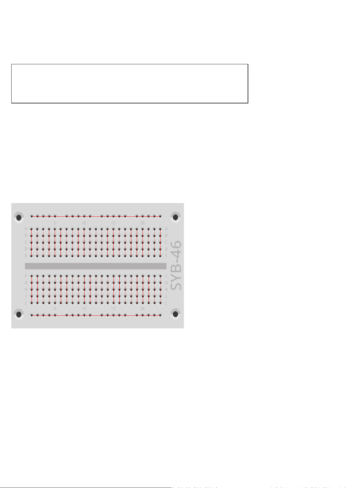
Breadboard
The Advents calendar contains a breadboard for the fast prototyping of electronic circuits, without the need to solder anything. Here, electronic components can be inserted straight into a hole of the grid.
Breadboard connections
All outer long rows of the breadboard are interconnected to each other via contacts (X and Y). These rows with contacts are often used as a
plus and minus pole to power the circuits. The other rows with contacts have five contacts each (A to E and F to J), which are connected
crossways with each other and there is a gap in the middle section of the board. Larger components can thus be plugged in and wired to the
outside.
LEDs
LEDs (light-emitting diodes) will glow as soon as current passes in flow direction through them. LEDs are shown in circuits with an arrowshaped triangle symbol, indicating the direction of flow from the positive pole to the negative pole or to the ground line. Almost any amount
of current can pass through an LED in the direction of flow; there is very little resistance. In order to limit the current flow and thus preventing the LED from breaking, a 220-ohm series resistor is usually installed between the connection pin used and the anode of the LED or
between the cathode and ground pin. Such a series resistor also protects the output of the Nano from excessive current. Series resistors are
already installed in the LEDs that come with the Advent calendar and you can thus connect them straight to the pins.
Page 2
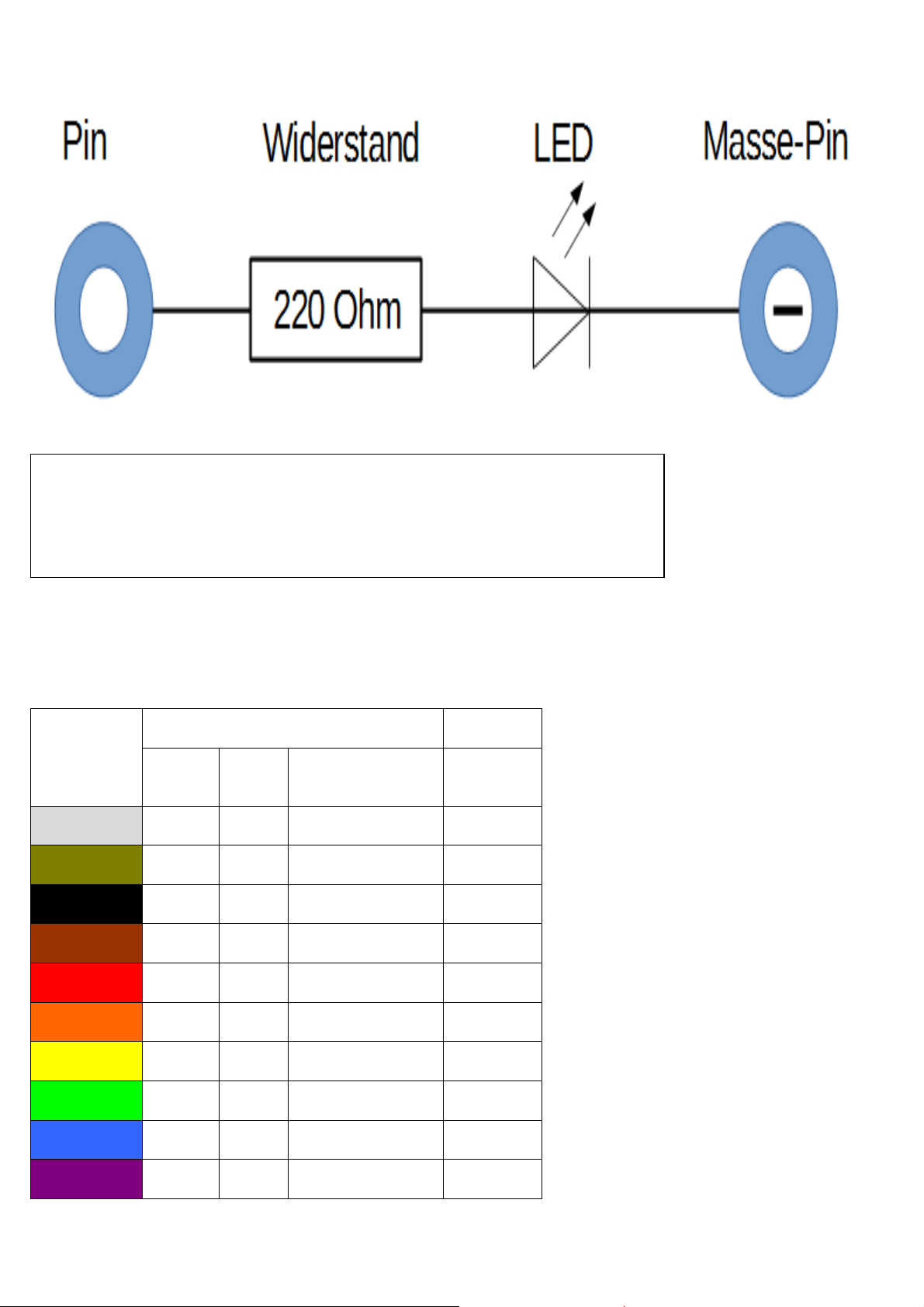
Circuit diagram of an LED with a series resistor.
How do you connect an LED?
The length of the two connecting wires of an LED is different. The longer leg is the positive pole,
the anode; the shorter leg is the cathode. Easy to remember: The plus sign has a dash more than the
minus sign and thus makes the leg somewhat longer. Besides, most LEDs are flat at the minus side,
similar to the minus sign. Also, easy to remember: Cathode = cut leg.
Resistors and colour codes
Resistors are used to limit current on sensitive electronic components and as series resistors for LEDs. Resistance is measured in ohms.
1,000 ohms equal to one kilo-ohm, abbreviated KΩ. 1,000 kilo-ohms equal to a mega-ohm, abbreviated MΩ. The Omega sign Ω is widely
used in conjunction with the metric unit.
Colour Resistance value in ohm:
Ring 1
(tens)
Silver
Gold
Black
Brown 1 1 101 = 10 ±1 %
Red 2 2 102 = 100 ±2 %
Orange 3 3 103 = 1,000
Ring 2
(ones)
0 100 = 1
Ring 3
(multiplier)
10−2 = 0.01 ±10 %
10−1 = 0.1 ±5 %
Ring 4
(tolerance)
Yellow 4 4 104 = 10,000
Green 5 5 105 = 100,000 ±0.5 %
Blue 6 6 106 = 1,000,000 ±0.25 %
Violet 7 7 107 = 10,000,000 ±0.1 %
Page 3

Grey 8 8 108 = 100,000,000 ±0.05 %
White 9 9 109 = 1,000,000,000
The coloured rings on the resistors indicate the resistor value. After a little practice, they are much easier to make out than the tiny numbers,
which are still found on very old resistors.
Most resistors have four such colour rings. The first two colours are used for the digits, the third for a multiplier and the fourth for the tolerance. This tolerance ring is usually gold- or silver-coloured – basically, colours, which are not used for the first rings. Thus, the direction of
reading is always evident. The tolerance value itself plays no serious role in digital electronics. The table shows how to interpret the ring
colours of resistor.
The direction how a resistor is installed is not important. However, the direction of installation is very important in the case of LEDs.
Precautionary measures
You should never attempt to connect some Arduino pins and then wait for what happens.
Not all of the Arduino pins can be freely programmed. A few are fixed for power supply and other
purposes.
Some Arduino pins are connected directly to the microcontroller, and that is why a short circuit can
destroy the Arduino completely - at least in theory. Arduino boards are amazingly resistant to circuit faults. However, you must always connect a series resistor in between when connecting two
pins via an LED.
For logic signals, some Arduino compatible boards require 3.3 V, other 5 V. The Nano in this Advent calendar uses a +5V signal as logical high or true.
Day 1
Today on the Advent calendar
•Nano (Arduino compatible board)
Nano preparation
For the Nano to work you will need:
•PC with Windows
•MicroUSB cable
•Driver
PC and Nano are connected with a MicroUSB cable. Almost all modern smartphones use this type of connector so, most likely, you will not
need to purchase such a cable. The cable is used for power supply and also for data transmission.
Connect the cable to a USB 2.0 port on your PC, if possible. You may encounter problems with the connection, if you use an USB 3.0 port.
Software installation in a nutshell
Four steps to install the driver:
Page 4
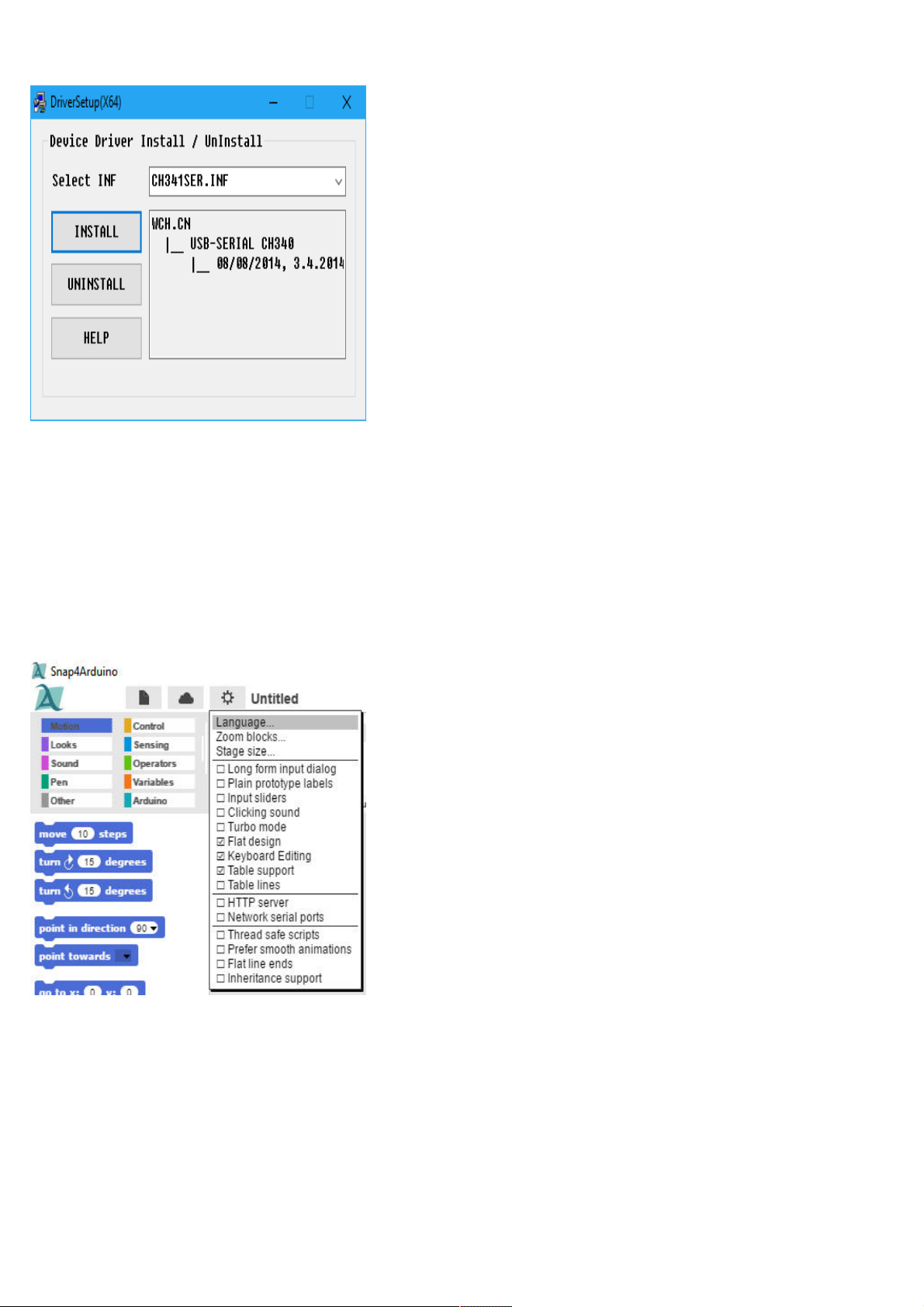
Installation of the device driver.
1. Download the example programs and the driver from www.buch.cd. Enter the code 15003-5 and follow the instructions on the screen.
2.Extract the ZIP archive into a folder anywhere under the Windows User folder.
3. Connect the Nano using the USB cable and then run the file
CH341SER.EXE
to install the driver. During installation confirm a request from
the Windows User account control.
4. In the installation screen click Install and wait until the installation of the driver is confirmed.
The LED glows
We use the easy-to-learn Snap4Arduino programming language for most Advent Calendar projects. You will find it among the Advent calendar downloads. Or you can download the latest version from snap4aruino.org .
The Snap4Arduino
Configuration
tool.
Page 5
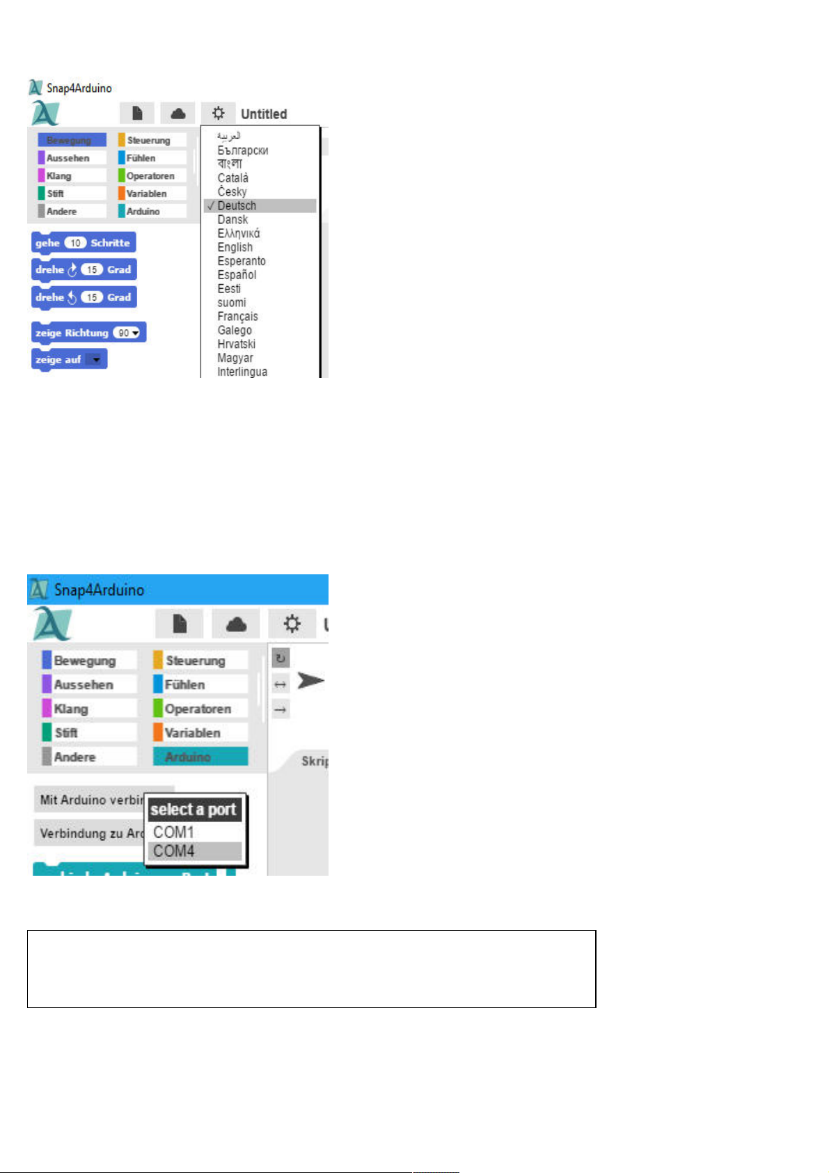
English
Select
in the list.
In Snap4Arduino click the Configuration icon and select Language from the menu.
However, you will need to establish a connection between PC and Nano, before you can start programming. For this purpose, we have the
StandardFirmata software preinstalled on our Advent calendar Nano.
In Snap4Arduino, switch to the Arduino block in the top left corner and click Connect to Arduino. If only one COM interface appears, select
it. If two interfaces are shown, then usually the lower one is the correct one.
Confirm the message with OK.
Choose an interface for the connection.
Error launching a new program.
When you launch a new program in Snap4Arduino, sometimes the connection to the Arduino is
lost. Re-connect the Nano with one click, if such an error occurs when a new program is launched.
Page 6
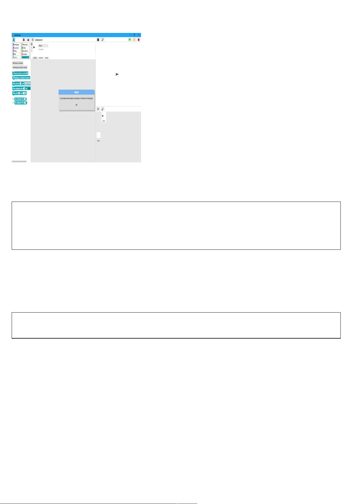
The connection to the Nano was successful.
The program
In Snap4Arduino, you do not need to type any programming code. The blocks are simply positioned by drag-and-drop. The block palette on
the left in the window contains blocks of code arranged by topic.
Advent Calendar programs
Download the Advent Calendar programs from www.buch.cd or build one each day yourself with the illustration as your guidance. Unzip
the ZIP file from the download to a directory on the hard drive. Then in Snap4Arduino click the file icon at the top on the left and select
Import to import the programs into Snap4Arduino. The programs are in XML format. Once imported, the programs will be shown in their
own library, which you can access via the Open menu item.
The first program
01led01
uses the most important block codes:
Most of the programs will start When the little green flag is clicked in the Control tool
continuous in the Control tool it an infinite loop that is repeated forever.
Set up the digital pin... to... in the Arduino tool will set one of the Nano’s digital pins to the logical true or false value. You will find the green
block for logical values in the Operators tool. You can toggle between the true and false values directly in the block.
LED on pin 13
The Nano has its own LED, which is controlled via pin 13. It displays the status without the need of additional hardware.
wait... sec in the Control tool will have the program wait for a certain time before the next step is executed.
This is how the program works
The program will start when you click on the green flag in the upper right corner.
Page 7
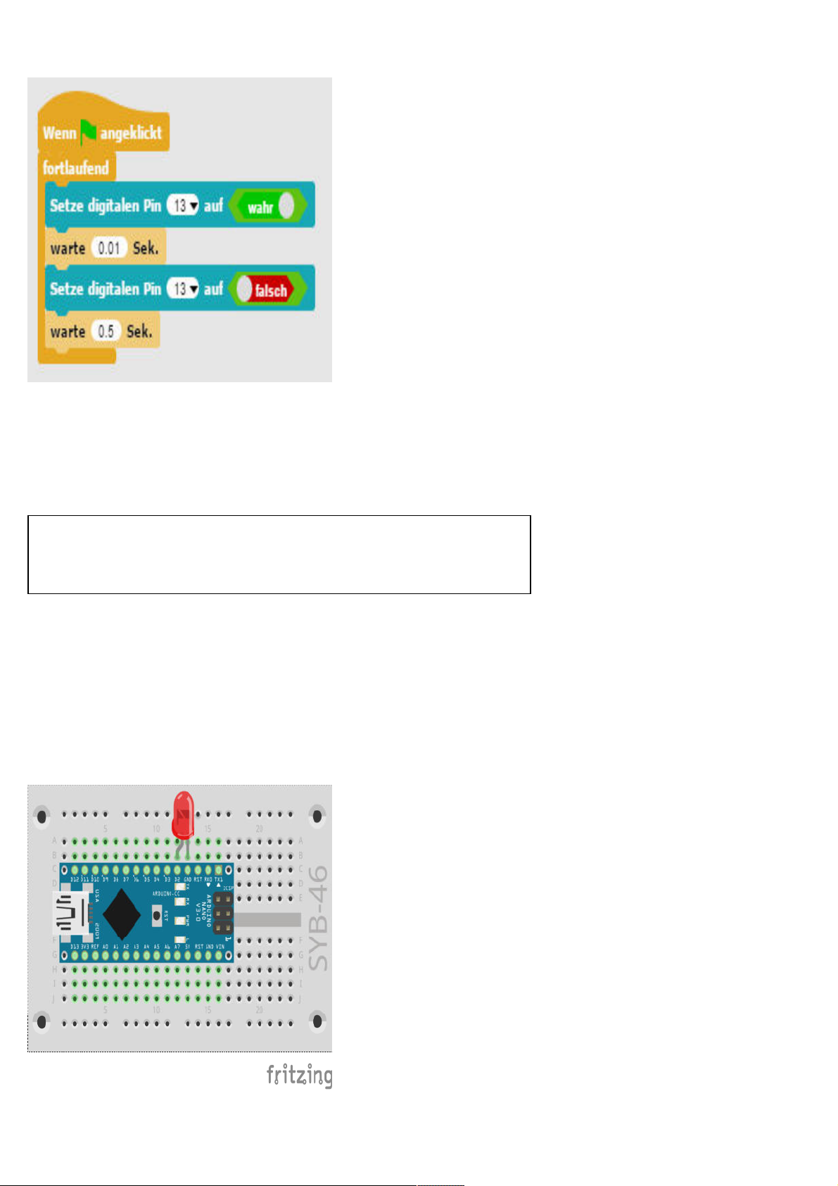
01led01
The
program will make the Nano LED flash.
A continuous loop will have the LED flash endlessly; that is, until the user clicks on the red Stop icon at the top on the right in
Snap4Arduino.
When the LED on pin 13 turns on, a waiting time of 0.01 seconds follows. This is the time the LED will be lit. Then the LED on pin 13 turns
off again. The program will now wait for half a second. That way, the LED will only light up briefly, while it is dark for a relatively longer
time. The cycle is then repeated.
Note: Decimal Point
Like most American programs, also Snap4Arduino uses the dot as a decimal separator
while in Germany a comma is used.
Day 2
Today on the Advent calendar
• 1 Breadboard (SYB 46)
• 1 red LED with built-in series resistor
Alternating flashing light
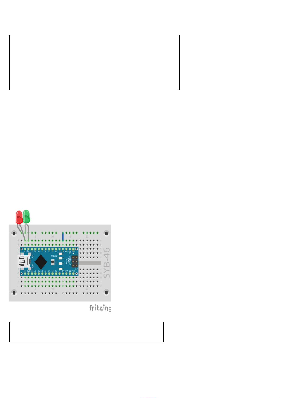
02led02
is a simple program for two LEDs that will flash alternately.
Alternating flashing light on the Nano
Page 8
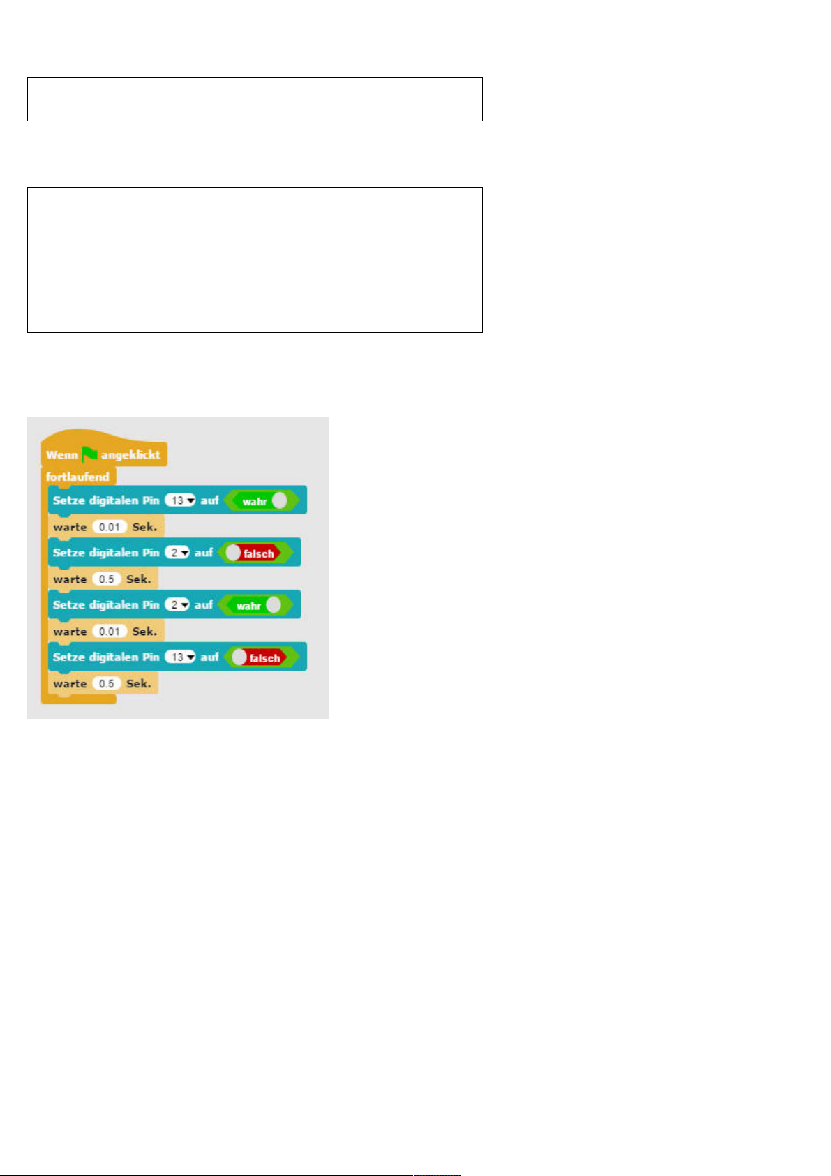
Components: 1 Breadboard, 1 red LED with built-in series resistor
Make sure that the LED cathode (short leg) is connected to the GND pin and the anode (long leg) to the D2 pin.
Nano pins
All pins with D… are digital inputs or outputs, which can have the values true
or false (on or off). Pins with A… are analogue inputs. GND pins are ground
wires. Arduino compatible boards work with different voltages and by default
they come with two different plus pins. Pin 3.3 supplies a voltage of +3.3 V.
Pin 5V supplies a voltage of +5 V. Our Advent calendar Nano requires a +5 V
for a logical true signal, other boards need only +3.3 V.
The program
02led02
The
program will have the built-in Nano LED and an externally connected LED flash in turns.
02led02
The
program features two LEDs flashing alternately.
This is how the program works
A continuous loop enables the two LEDs to blink endlessly; that is, for as long as the user does not click on the red Stop icon at the top on
the right in Snap4Arduino.
After the built-in LED on pin 13 is turned on, a waiting time of 0.01 seconds ensures that StandardFirmata is not “swallowing” a command.
Most Arduino compatible boards should always have a minimum wait time between two pins. For the Advent Calendar Nano, this is not
really essential. Finally, the LED on pin 2 is turned off. The program will now wait for half a second.
Using the same method, the LED on pin 2 is then turned on and the LED on pin 13 is turned off. The cycle starts again from the beginning
after half a second.
Day 3
Today on the Advent calendar
•Jumper wire (insulated)
Jumper wire
Today we have included a jumper wire in the Advent calendar. The jumper wire is used to create short connection bridges to connect rows
on the breadboard. Cut the wire to the appropriate lengths needed for the experiments using a small side cutter. We recommend cutting the
Page 9
wire end at a slight angle thus creating a kind of wedge, which will allow you to plug the wires into the breadboard easily. Remove about half
a centimetre of the insulation at both ends.
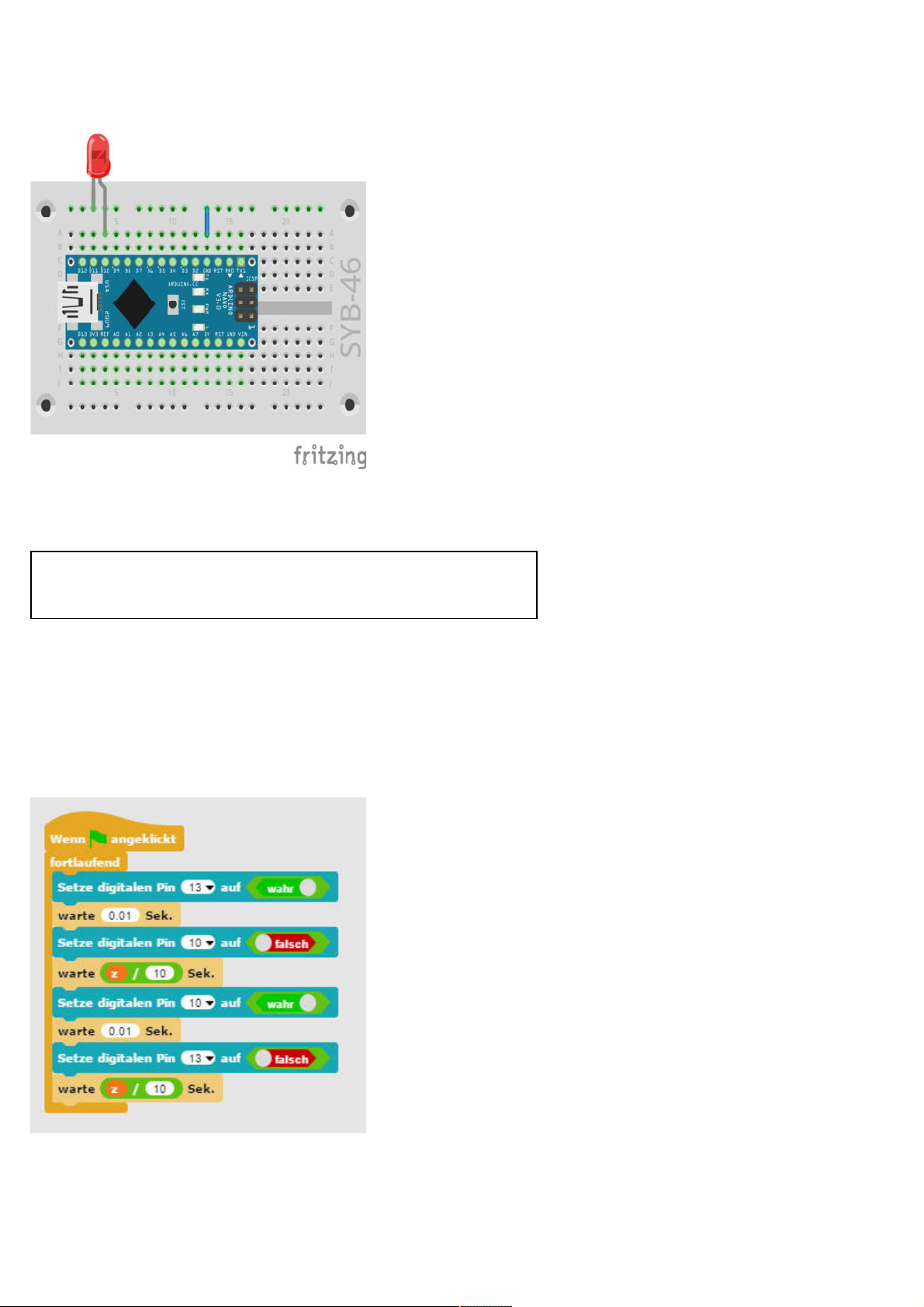
Alternating flashing LED on the Nano.
LEDs flash at an adjustable speed.
The experiment of the 3rd day lets two LEDs blink alternately. This time, however, you can adjust the speed.
Components: 1 Breadboard, 1 red LED with built-in series resistor, 1 wire
jumper
Today’s circuit shows the typical circuit configuration on the board. One of the horizontal contact strips will be used as ground line, which
we connect to the GND pin on the Nano via a wire jumper. Make sure when configuring the circuit that the LED cathode (short leg) is
plugged into the GND pin and the anode (long leg) is connected to pin 10 in our circuit of today.
The program
03led03
The
ed to pin 10, will flash in turns. You can control the flash frequency via a slider on the screen.
program works similar to the one of yesterday and again the built-in LED on the Nano and the external LED, this time connect-
03led03
The
program lets two LEDs blink alternately and at an adjustable speed.
This is how the program works
Also, here, the Continuous loop lets the two LEDs flash alternately forever. We will use a variable instead of a fixed time between the
Page 10
change.
Variables in Snap4Arduino
Variables are tiny storage locations that contain a number or any similar information
for a program to recall. When the program is closed, these variables will be cleared
automatically. However, first the variables must be created in Snap4Arduino using the
command tool Variables and the button New variable, before we can use any. You can
then drag the icon of the newly created variable from the block palette into a specific
field of a block within the program. The block palette offers also various other blocks
for reading and changing variables.
After a variable is created, it appears as an orange icon on the stage. Here, the current value of the variable is always shown. Right-click on
this icon and select the Controller option.
Take the values 1 and 10 to set the Minimum value and Maximum value. Variables could have any value, but Snap4Arduino however can
only set integers with the sliders.
In the program, the set value of the variable z is divided by 10 to obtain values between 0.1 and 1.0 seconds. The block palette Operators
has blocks for basic calculation operations.
Day 4
Today on the Advent calendar
• 1 green LED with in built-in series resistor
LEDs flash randomly.
The experiment from the 4th day features three LEDs flashing in random order. The two external LEDs are plugged into the breadboard
close to each other, since the program requires successive pin numbers. The third LED is the LED soldered to the Nano board and has the
pin number 13.
Three LEDs blink randomly.
Components: 1 Breadboard, 1 red LED with built-in series resistor, 1 green
LED with built-in series resistor, 1 wire jumper
The program
The program
04led04
is similar to the one we used on Day 2. Also, here, several digital pins are switched on and off in a row in an endless
Page 11
loop. This time, pins are chosen at random.
How are random numbers generated?
In general, we assume that nothing randomly can happen within a program
– then how is it possible that a program is able to generate random numbers? If a large prime number is divided by any value, the x decimal point
produces numbers, which are sheer unpredictable. They will also change
without any regular pattern, if the divisor is constantly increased. The result seems to be randomly, but it can be reproduced at any time by an identical program or the repeatedly invoking of the same program. Now, if you
take a number that was composed of some of these digits and you then
divide it by a number that you take from the current time second or from
the contents of any memory location on the computer, you will get a result
that cannot be reproduced and this then is called a random number.
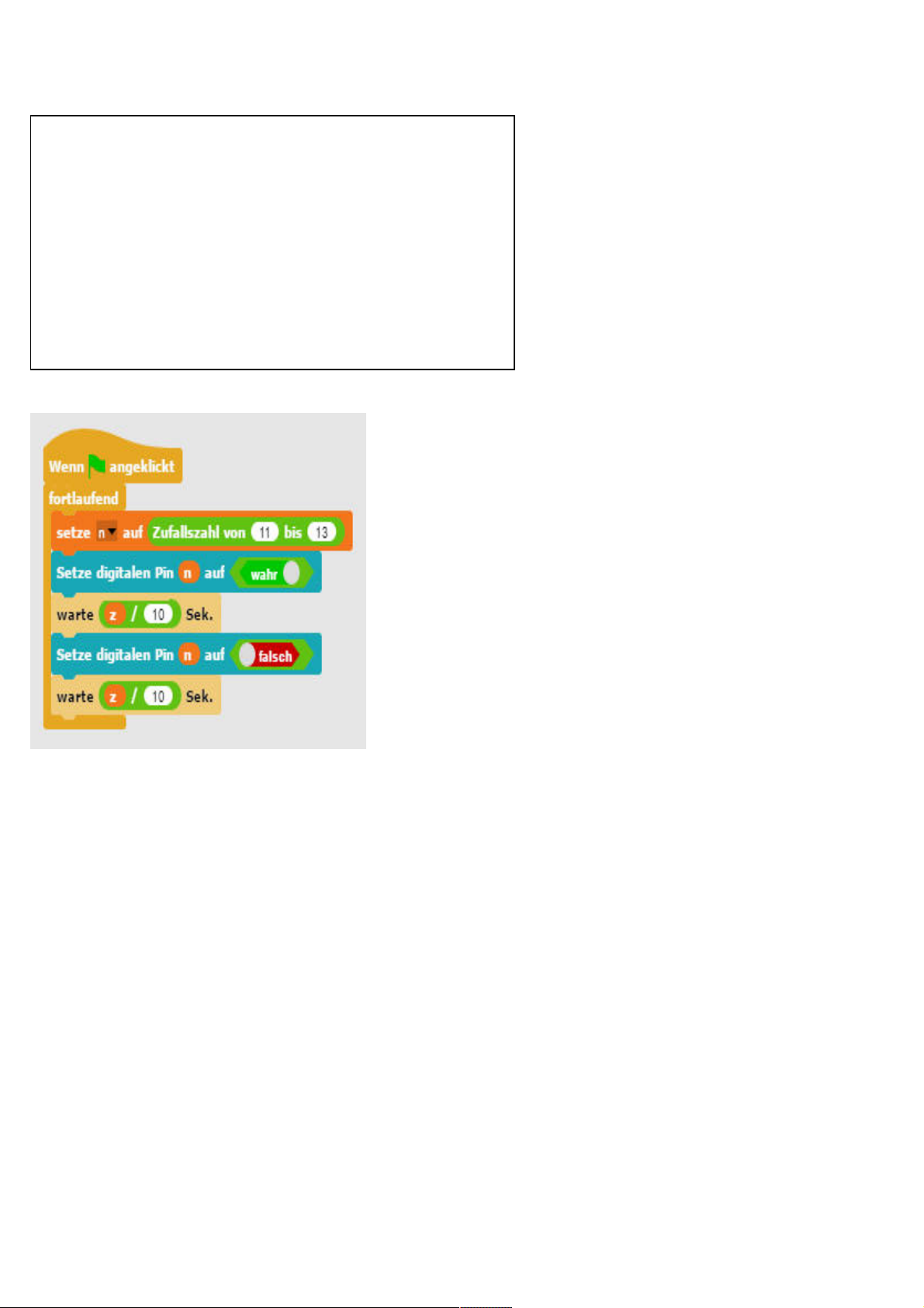
04led04
Program
lets LEDs blink randomly.
This is how the program works
At the start of each infinite loop run, the variable n is set to a random number between 11 and 13. This then indicates the pin number of the
LED that should be lit. The circuit thus needs three successive pin numbers.
The speed how fast the colours change is controlled by means of a variable z, which is set via a slider and will then apply to each switching
operation.
The randomly selected LED is switched on for the set time and then switched off for just as long. A new LED is randomly selected in the next
loop run. It may well happen that the same LED goes on several times in a row.
Day 5
Today on the Advent calendar
• 1 yellow LED with built-in series resistor
Traffic light
The experiment of the 5th day will switch traffic lights by means of three LEDs in a typical series from red to red/yellow to green and via
yellow back to red.
Page 12
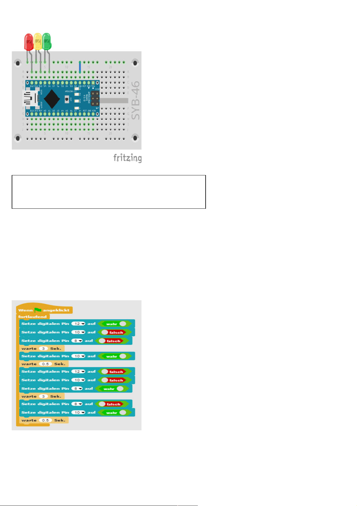
Traffic lights with three LEDs.
Components: 1 Breadboard, 1 red LED with built-in series resistor, 1 yellow
LED with built-in series resistor,1 green LED with built-in series resistor, 1
wire jumper
The program
The program
in an endless loop. In the intermediate phases of red/yellow and yellow, the traffic light will go on for 0.5 seconds each, in the phases of red
and green the duration is 3 seconds each. You can set these times also differently in the wait...sec blocks.
05ampel01
is similar to the one we used on Day 3 . Also, here, a combination of LEDs are switched on and off one after the other
This is how the program works
Each run of the infinite loop starts with the red phase of the traffic lights with the yellow and green LEDs switched off. After 3 seconds, the
yellow LED is also switched on. After a short red/yellow phase, which will last 0.5 seconds, the red and yellow LEDs are switched off and
the green one is switched on. The green phase lasts 3 seconds, followed by a short yellow phase of 0.5 seconds, and the infinite loop starts a
new run with red.
Program
05ampel01
lets LEDs blink alternately.
Page 13
Day 6
Today on the Advent calendar
•1 Button
•1 10-kOhm-resistor (brown-black-orange)
Toggle LEDs using a switch
The experiment of the 6th day shows how to switch two LEDs via a button.
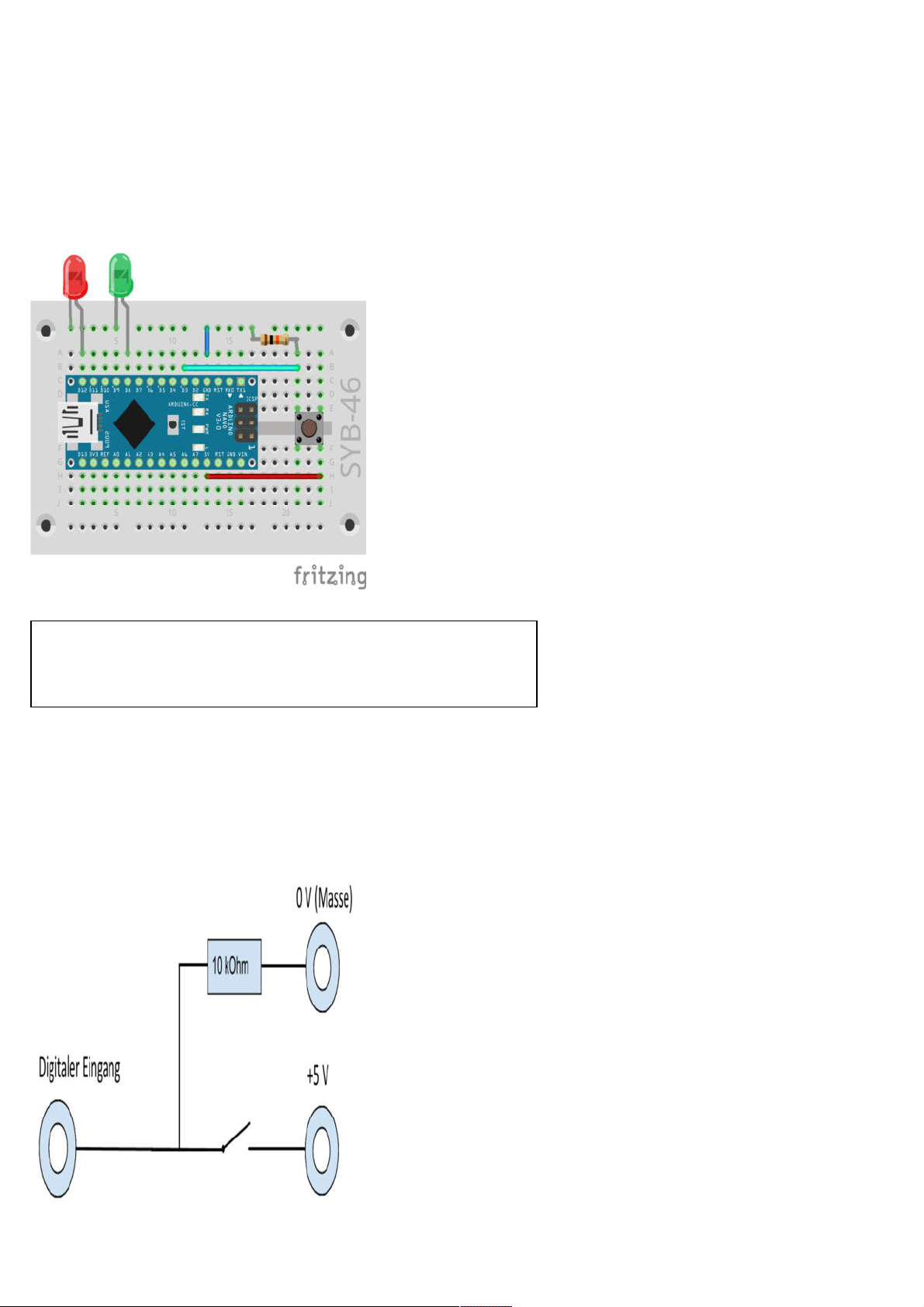
Two LEDs controlled by a button.
Components: 1 Breadboard, 1 red LED with built-in series resistor, 1 green
LED with built-in series resistor, 1 button, 1 10-kOhm-resistor (brown-blackorange), 3 wire jumpers of different lengths
Digital pins are not only used for the output of data, for example via LEDs, but also for data input. For the input, we will use a button in our
project of today, which is plugged directly onto the breadboard. The button has four connection pins, whereby the two opposite each other
(large distances) are interconnected. As long as the button is pressed, all four connectors are interconnected. Unlike a switch, a button does
not latch. The connection is immediately cut when the button is released.
If a digital input has a +5V signal, it will be evaluated as logically true.
Circuit diagram of a button with pull-down resistor.
Page 14
If the button were open, the input would not have a clearly defined state. A program querying this pin could produce random results. To
prevent this, a relatively very high resistance - usually 10 kOhm - is connected to ground. This so-called pull-down resistor pulls the status of
the input pin down to 0 V, if the button is open. Because the resistance is very high, there is no risk of a short-circuit for as long as the button is pressed. When the button is pressed, +5 V and the ground line are connected directly via this resistor.
The program
The program
LED is lit while the button is not pressed.
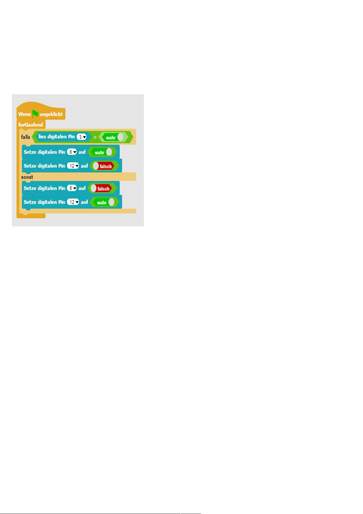
06led06
turns on the green LED on pin 8, while it turns off the red LED on pin 12, when the button is pressed. Only the red
The program
06led06
lets you switch two LEDs with a button.
This is how the program works
The if…else… block of the Control block palette will execute the blocks within the upper brackets, whenever the query returns the value true.
If this is not the case, the blocks within the brackets below will be executed.
The query reads the value of the digital pin 3 via a block from the Arduino block palette and checks whether this is true. Digital inputs can
only have the values true or false.
If the value is true, then the button is pressed. If this is the case, the LED on pin 8 is turned on and the LED on pin 12 is turned off. If this is
not the case, pin 3 has the value false and the LEDs are switched exactly the other way.
Day 7
Today on the Advent calendar
• 1 red LED with built-in series resistor
Dimming the LED
The experiment of the 7th day will dim an LED.
Page 15
One LED is dimmed, the second one is lit with full brightness.
Components: 1 Breadboard, 2 red LEDs with built-in series resistors, 1 wire
jumper
LEDs are typical components used in digital electronics to output signals. LEDs can have two different states, on and off, 0 and 1 or false
and true. The same is true for the digital pins, which are defined as outputs. Logically that would mean, however, it is impossible to dim an
LED.
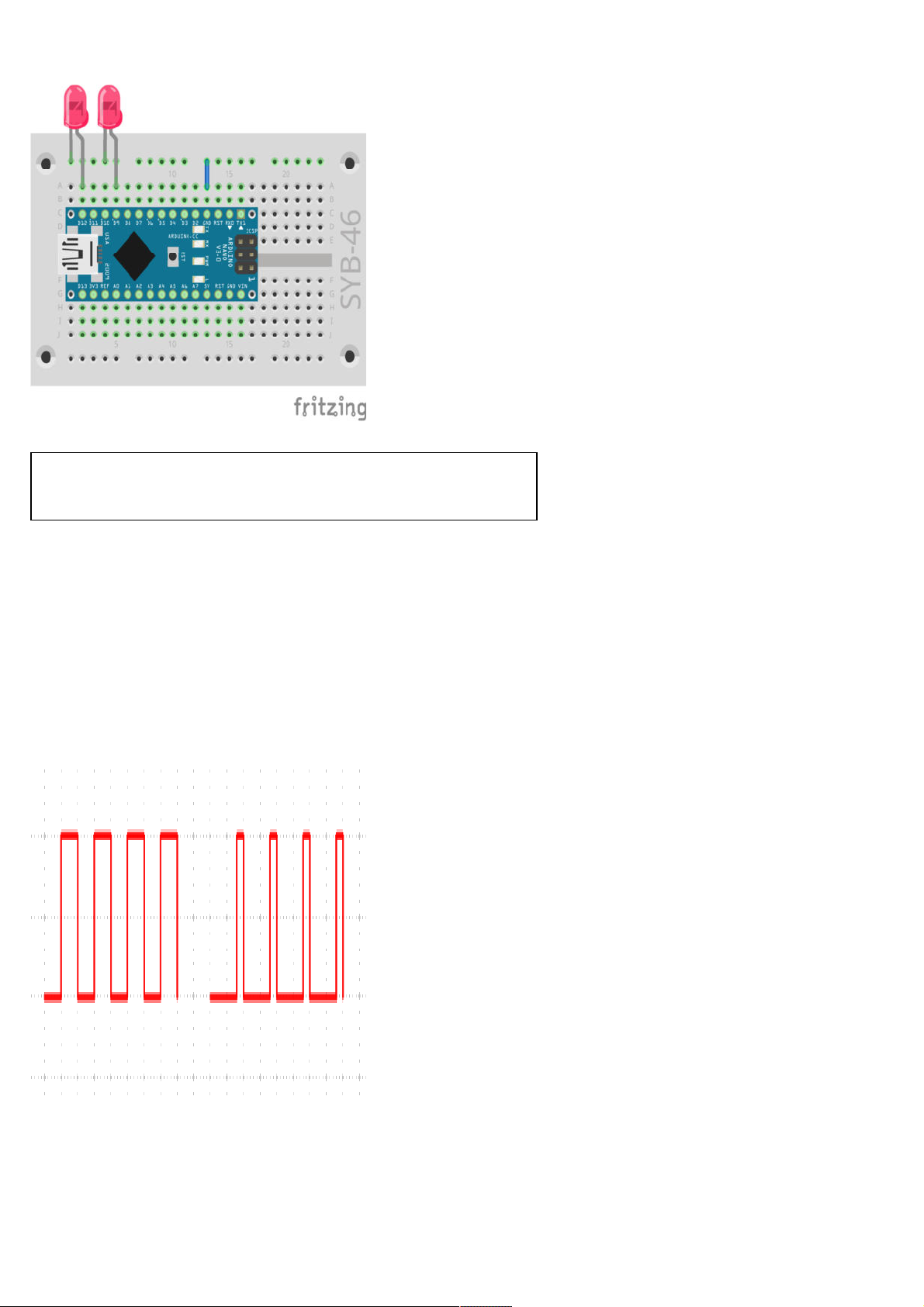
But a trick makes it possible to control the brightness of an LED on a digital pin. If an LED is flashing fast enough, the human eye cannot
perceive this anymore as flashing. The technique, known as pulse width modulation (PWM), produces a pulsating signal, which turns on
and off at very short intervals. The signal voltage is always the same, only the ratio between level false (0 V) and level true (+3.3 V) is
changed. The duty cycle is the ratio of the length of the switched-on state to the total duration of a switching cycle.
The smaller the duty cycle, the shorter is the LED glow time within a switching cycle. This will make the LED appear darker than a permanently switched on LED.
Left: Duty cycle 50% - on the right: Duty cycle 20%.
Page 16

Pins for PWM signals
The pins 3, 5, 6, 9, 10 and 11 in the circuit diagrams are marked with the ‘ symbol. These pins are
used for pulse width modulation. In Snap4Arduino you cannot even select the other pins in the
Setup pin... to.... block
The program
The program
07pwm01
dims the LED on pin 9 darker or brighter in a sequence. In comparison, the LED on pin 12 glows in full brightness.
The program
07pwm01
dims an LED at the PWM output.
This is how the program works
First pin 12 as the digital pin is set to true. Then two variables are defined: bright indicates the PWM value for the brightness of the LED,
and increment indicates the increment during dimming. The actual values of both variables are displayed in real-time in the upper right
corner of the stage. Now starts an infinite loop. The actual value of the bright variable is output to pin 9 as a PWM value during each loop
run. Then the value of the bright variable is increased by the increment.
Whether the bright value has reached the 0 or 100 limit, is checked during the next step. In this case, we insert an or block, which in turn has
room for two more queries. If at least one of these two queries is true, the or block returns the value true and the content of the if block is exe-
cuted.
Two equality queries will check whether the value of the variable bright has reached the 0 or 100 value. If this is the case, the increment
variable is set to a new value. Because Snap4Arduino does not provide a way to invert the algebraic sign of a variable, we will use the minus
operator and subtract the value of the variable from 0, which will deliver the same result. The program will pause for half a second at the
moment the direction is reversed, that is, the LED is either very bright or very dark.
Finally, the program pauses during each loop run for 0.05 seconds. Then the infinite loop restarts and delivers a new PWM value to the
LEDs.
Day 8
Today on the Advent calendar
• 1 green LED with in built-in series resistor
Pedestrian lights
The experiment of the 8th day shows how to switch pedestrian lights with a button. By pressing the button, the typical lights sequence of a
pedestrian light begins. In an inactive state, the pedestrian light is red, the traffic light is green.
Page 17

The pedestrian lights are controlled by a button.
Components: 1 Breadboard, 2 red LEDs with built-in series resistors, 1 yellow
LED with built-in series resistor, 2 green LEDs with built-in series resistors, 1
button, 1 10-kOhm-resistor (brown-black-orange), 3 wire jumpers (different
lengths)
The program
The program
the home position. The pedestrian light is red, the traffic light is green. The traffic lights sequence starts as soon as the button is pressed.
The program will pause after a cycle until the button is pressed again.
08traffic_light02
controls pedestrian lights with a modelling clay contact. A click on the green flag puts the traffic light into
The program
08traffic_light02
controls a pedestrian light with a modelling clay contact.
This is how the program works
The program starts with five LEDs that are put in the traffic lights home position. Then the main loop of the program will run. It consists of
a single-case if query. Nothing will happen for as long as the button is not pressed. If the button is pressed, the lights sequence will run
though. We have extended the program of Day 5 by the circuit for the pedestrian lights during the red phase of the traffic lights.
Page 18

Day 9
Today on the Advent calendar
• 1 blue LED with in-built series resistor
On-screen game
This game has a ball flying across the stage and bouncing off the coloured edges. Every time the ball comes in contact with an edge will cause
the LED of the same colour to flash briefly.
The Snap4Arduino paint program.
Components: 1 Breadboard, 1 red LED with built-in series resistor, 1 yellow LED with built-in
series resistor,1 green LED with built-in series resistor, 1 blue LED with built-in series resistor, 1
wire jumper
Snap4Arduino has its own little paint program that can be used to draw on the stage. To do this, click in the object palette on the Stage icon
in the lower right, select the Background tab and then the brush icon Paint a new costume.
You can also use the same paint program, which you used to draw on-stage, to make a circle out of the default object. Click the object in the
object palette, and then click the Costumes tab. Again, you will find the brush symbol for the paint program. Then click the Scripts tab to go
back to the script area in Snap4Arduino.
The program
The program
with moving the ball across the stage.
Each of the other four blocks will cause an LED to flash every time the ball touches an area of a matching colour.
09game01
consists of five independent program blocks. The main program is launched by clicking on the green flag and it starts
This is how the program works
With a click on the green flag, the ball is positioned at the absolute origin in the coordinate system in the middle of the stage and a random
direction of movement is defined. Now a continuous loop starts which will check during each run, whether the ball is in contact with the
edge, and if this is case, it will push it off. In addition to that, the ball is moved eight increments in the direction of movement.
Page 19

Four LEDs show events within the game.
Coloured bars on the stage.
The other four program blocks are triggered, whenever the ball touches a certain colour on the stage. Click in the colour area in the
touch…? block to select this colour. Now you can select the colour from the colour palette or directly on the stage. Each one of these four
blocks will cause the LED with the matching colour to flash for 0.5 seconds.
Day 10
Today on the Advent calendar
1 x modelling clay
• 1 20-MOhm resistor (red-black-blue)
Control the LED with a clay sensor
The experiment of the 10th day shows how sensor contacts made from modelling clay work.
Page 20

Controlling the LED with a clay sensor.
Components: 1 Breadboard, 1 red LED with built-in series resistor, 1 green
LED with built-in series resistor, 1 20-MOhm resistor (red-black-blue), 1 wire
jumper, 2 clay contacts
The second clay contact on the right is the ground contact. Preferably, you keep touching it all the time, while you press and release the clay
sensor on the left.
This is how the sensors work
The pin, which serves as an input, is connected to +3.3 V via an extremely high-resistance (20 MΩ) resistor, so that a weak, yet highly defined signal is applied. A person, who is not necessarily fluttering in the air, is always grounded and delivers low level potential via the electrically charged skin. When the person touches a sensor contact, the weak high signal is superimposed by the much stronger low level of the
fingertip and pulls the pin to low level.
However, how high the resistance between hand and mass actually is will depend on many things, including footwear and flooring. Barefoot
in wet grass makes for the best connection to grounding, but standing on a stone floor usually works very well. Wooden floors are more
insulated; plastic floor coverings are all too often positively charged. In addition, a grounding contact is provided for each circuit, similarly
to the sensor buttons on elevators and doors, so that the circuit always works. Thus, the ground connection will be produced in any case
when you touch this button and the actual sensor simultaneously.
Page 21

Circuit diagram for sensor contacts at the Arduino.
Modelling clay is as conductive as human skin. You can easily form it into any shape, and a clay contact is much better than a simple piece of
wire. The touch area between hand and contact is significantly larger. That way a “wobbly contact” is easily avoided. Cut a piece of wire that
is approximately ten cm long. Remove about one centimetre of the insulation at both ends and stick one end into a piece of modelling clay.
Insert the other end into the breadboard as shown in the figure.
Because Snap4Arduino will always switch on the pull-down resistors installed in many Arduino compatible boards, the digital inputs are
usually pulled to 0 and even without being touched, they will have a low level or no defined state at all. However, Arduino compatible
boards also have analogue inputs, which work very well for sensor contacts. Analogue inputs deliver values between 0 (low level) and 1023
(high level). Depending on the board type, values in the range of 100 to 200 are good limit values in order to make the distinction between
sensor contacts touched and not touched.
The program
The program
10clay01
turns on the LED when the clay contact is touched, and turns it off when released.
The program
10clay01
switches LEDs when the clay contact is touched.
This is how the program works
The variable x always shows the actual value of the analogue pin 2 on the stage. If it is less than 200, the LED on the digital pin 8 is switched
on and the LED on pin 12 is switched off within the if…else… query or vice versa, if this is not the case.
Day 11
Today on the Advent calendar
• 1 RGB LED with built-in series resistors
RGB-LEDs
A normal LED will always glow in one colour. The RGB LEDs used in the advent calendar can glow in various colours. Basically, three different coloured LEDs are installed in a transparent housing. Each one of these three LEDs has its own anode that connects to a digital Arduino pin. There is only one cathode that connects to the ground line. An RGB LED has thus four connection legs.
Page 22

Connecting pin of an RGB-LED
RGB LEDs legs have different lengths. That makes it easy to clearly identify them. However, unlike ordinary LEDs, here the cathode is the
longest leg.
Circuit diagram for an RGB LED with three series resistors.
The RGB LEDs work like three distinct LEDs and will therefore need three series resistors. These are already built into the RGB LEDs included in the Advent calendar.
RGB lighting effects
The experiment of the 11th Day shows the different colours of an RGB LED
Components: 1 breadboard, 1 RGB LED with built-in series resistor, 1
jumper wire
Page 23

Lighting effects of the RGB LED
The program
The program
loop. Our case is about the combination of three RGB LED colours.
Different colours of an RGB LED
11rgb01
is similar to the one we used yesterday. Also, here, several digital pins are switched on and off in a row in an endless
Additive colour mixing
RGB-LEDs makes use of what is called additive colour mixing. Here the
three light colours red, green and blue are added to ultimately produce
pure white. In contrast, a colour printer uses the subtractive colour
mixture method. Every colour acts as a filter on a white sheet, which
removes (subtracts) a part of the white-reflected light. Black is produced, when all three colours are printed on top of each other; no light
at all is reflected.
Page 24

Additive colour mixing
This is how the program works
In this program, always one and sometimes two-colour components are illuminated by turning them on and off in turns. This causes the
RGB LED to toggle between six different colours.
The speed how fast the colours will change is controlled by means of a variable z, which is set to a certain value at program start and will
then be used for each colour change. The user can interactively adjust this variable while the program is running.
Day 12
Today on the Advent calendar
• 1 20-MOhm resistor (red-black-blue)
RGB Colour mix with PWM
The experiment of the 12th day will mix the colours of the RGB LED using PWM signals.
Colour mix of an RGB LED
Components: 1 breadboard, 1 RGB LED with built-in series resistor, 2 20MOhm resistors (red-black-blue, 1 jumper wire, 3 clay contacts
Page 25

The program
The program
tacts are touched. This will generate various mixing colours. If a clay contact is released, this colour will stop changing the colour. The actual
values of all variables are displayed in real-time in the upper right-hand corner of the stage.
12rgb02
will dim two of the three colour components of an RGB LED to be periodically brighter and darker when the clay con-
This is how the program works
The variables bright_g and bright_b hold the PWM brightness values of the two-colour components green and blue, the variables increment_g and increment_b hold the increments by which the PWM values are changed. Basically, here we only switch between +5 and –5.
The red component of the RGB LED is always on at full brightness.
The program
12rgb02
will dim two of the three colour components of a RGB LED.
Two independent program blocks for the green and blue colour components of the RGB LED will start, when you click on the green flag. An
if… ... query checks whether the clay contact is touched. If yes, the brightness of the corresponding colour component is changed by the
increment. If the brightness has reached one of the limit values, 0 or 100, the increment is reversed and at this point, the sequence of the
colour change is paused for 0.5 seconds.
Day 13
Today on the Advent calendar
• 1 yellow LED with built-in series resistor
Running lights
Running lights are popular effects on every occasion and not just in advertising and party rooms. The experiment of the 13th day will have
seven LEDs light up as running lights upon touching the clay contact.
Page 26

Running lights with seven LEDs.
Components: 1 Breadboard, 2 red LEDs with built-in series resistors, 2 green
LEDs with built-in series resistors, 1 blue LED with built-in series resistor,1 20MOhm resistor (red-black-blue), 1 wire jumper, 2 clay contacts
The program
The program
do not have to be filled by the program in Snap4Arduino; you can instead pre-set initial values directly in the program code.
The list variable is shown on the stage.
13chase01
uses a list of variables, where the pin numbers of the digital pins, which will be used for the LEDs, are stored. Lists
A loop runs over the length of the list and one after the other will turn on each LED for 0.1 seconds. This loop is repeated forever.
Page 27

The program
13chase01
controls a running light by means of a list variable.
This is how the program works
When the green flag is clicked, a list variable x is created with the pin numbers of the seven pins used for the LEDs. The main loop of the
program will then start, which again consists of a single if… query.
Upon touching the clay contact, the loop counter i is set to 1. Then a loop will run as many times as there are elements in the list. The digital
pin matching the respective list element will switch on for 0.1 seconds. The loop counter will then increase by 1. In that way every LED is
flashing once.
Day 14
Today on the Advent calendar
•1 10-kOhm-resistor (brown-black-orange)
We will need this resistor in the next few days.
LED dice
Most likely everyone has one at home but almost certainly everyone knows the traditional dice with its six sides, each face showing a certain
number of dots. An electronically controlled dice with pips illuminating when the button is touched, is by far a much cooler version. We will
also arrange them like those on a dice and we will not just use one to six LEDs in a row. The dice has dots which are typically arranged in a
square formation Thus we will need seven LEDs. However, instead of seven digital pins, we will only need four to control the LEDs, since a
dice uses the dots in pairs to show even numbers.
LED dice with seven LEDs using the clay sensor.
Page 28

Components: 1 Breadboard, 2 red LEDs with built-in series resistors, 2 green
LEDs with built-in series resistors, 2 yellow LEDs with built-in series resistors,1
20-MOhm resistor (red-black-blue), 2 wire jumpers, 2 clay contacts
This circuit requires both side rails of the breadboard for ground lines. So, this time we connect the clay a bit different. We will use only six
externally connected LEDs and the LED on pin 13 as the LED in the middle to display odd dice numbers.
The program
The program
14dice01
simulates a dice with six sides. We throw dice by touching the clay contact.
The program
14wuerfel01
simulates a dice with six sides.
This is how the program works
When the user clicks the green flag, an endless loop is executed, which repeatedly checks whether the clay contact is touched. If this is the
case, the four pins used for the LEDs are first switched off, which will delete previously displayed scores.
Now a random number between 1 and 6 is stored in the variable w. For each possible score we have individual if…... blocks that will turn on
the corresponding LEDs.
Day 15
Today on the Advent calendar
•15-kOhm potentiometer
Running light controlled by the potentiometer
Today we use the potentiometer of the advent calendar, which is a resistor that can be adjusted by turning the knob and which may have
values between 0 Ohm and 15 kOhm. With the potentiometer we can build a voltage divider that will deliver any voltage between 0 V and
+5 V. This analogue voltage must be converted to a digital value, so that the program is able to process it.
Page 29

Running lights with seven LEDs and potentiometer.
Components: 1 Breadboard, 2 red LEDs with built-in series resistors, 2 green
LEDs with built-in series resistors, 1 blue LED with built-in series resistor,1 15MOhm potentiometer, 4 wire jumpers (of different lengths)
The program
The program
The program
15chase02
15chase02
controls an LED bar based on the potentiometer setting.
This is how the program works
The numbers of the pins used for the LEDs are stored in a list. A loop turns on each LED for a certain time and then turns it off again.
The analogue pin 5 is queried during each loop run, and its value that could be anything between 0 and 102 is divided by 1024 in order to
get a value between 0 and 1. This value defines how long each LED is lit.
The analogue inputs of the Arduino will evaluate an analogue voltage value and deliver digital values between 0 and 1023. Here 0 stands for
0 V and 1023 for +5V voltage at the respective pin.
Page 30

Day 16
Today on the Advent calendar
•Battery box
Using the Nano without PC
You can use the Nano also without a PC and it will process a stored program. We will need an external power supply. This could be a USB
charger for mobile phones, a power bank or even a battery. Today the Advent calendar has a battery box included, where four AAA batteries
deliver a voltage of 6 V and a rechargeable battery of 4.8 V, latter is also enough to power the Nano. The batteries are not included.
The battery box is connected to the 5V and the GND pins on the Nano.
Components: 1 breadboard, 1 battery box, 1
jumper wire
Do not yet connect the battery box yet, as the PC must power the Nano until the new program is transferred.
The Arduino IDE
Snap4Arduino requires a permanent connection between PC and Nano due to the StandardFirmata software installed on the Nano. In order
to use the Nano independently without a PC, you will need the Arduino IDE. You will write the programs using the programming language C
and then transfer them straight to the Nano. When this is done, you can disconnect the PC.
How do you switch the Arduino off
The Arduino has no power switch, that is why you simply disconnect the power supply and it turns
off. The last saved program will be launched automatically the next time the power is turned on.
Pressing the reset button will achieve the same result.
Download the Windows Installer for the latest version of the Arduino IDE from www.arduino.cc/en/Main/Software or simply use the file
arduino-windows.exe
Windows Store.
under the downloads for the Advent calendar. Windows 10 users can also download and install the Arduino IDE from
Make sure you tick all the boxes in the Installation Options screen. Depending on your Windows configuration, the user account control may
ask for a confirmation.
Once installed, launch Arduino-IDE. Quit Snap4Arduino, if it is still running. Select Tools/Port from the Arduino IDE menu. In most cases,
only a single serial port will be displayed. Tick the box.
Page 31

Install the Arduino IDE.
In the Tools/Board menu select the Arduino Nano, if not automatically detected.
Select the appropriate board within the Arduino IDE.
Select File/Example/01.Basics./Blink to open a simple sample program that will cause the built-in LED on the Nano to flash.
Click on the round icon with the arrow in the upper left corner to upload the program to the Nano connected - this is also called flashing.
Once the upload is complete, the LED on the Nano flashes. You do not need to start the program.
Disconnect the USB connection from the PC. The LED turns off when the power supply is cut. Then connect the battery box containing the
four batteries or rechargeable batteries as shown in the figure. The LED starts flashing again, because the Nano will automatically launch
the last flashed program.
Flashing StandardFirmata
The blink program has overwritten the preinstalled StandardFirmata, since it is only possible to
install one program on the Nano. Before you can use Snap4Arduino again, you must use the Arduino IDE to re-flash the StandardFirmata on the Nano. You find the software in the
File/Examples/Firmata/Standard menu. Remember to remove the battery box, before you connect
the Nano to the PC.
Page 32

Day 17
Today on the Advent calendar
• 1 blue LED with in-built series resistor
Alternating blue light
The first program used with the Arduino IDE will feature two LEDs flashing alternately. You can run the program also with the battery box
without a PC after flashing.
Running lights with seven LEDs and potentiometer.
Components: 1 Breadboard, 2 blue LEDs with built-in series resistors, 1 wire
jumper
The program
File names in the Arduino IDE cannot start with a number, thus we rename the following program differently and use
int red = 6;
int blue = 8;
void setup() {
pinMode(red, OUTPUT);
pinMode(blue, OUTPUT);
}
void loop() {
digitalWrite(red, HIGH);
digitalWrite(blue, LOW);
delay(100);
digitalWrite(red, LOW);
digitalWrite(blue, HIGH);
delay(100);
}
_17blinklight01
.
This is how the program works
int red = 6;
int blue = 8;
The program starts with storing the two pin numbers used as two variables of the integer type. All Arduino IDE programs consist of at least
two functions:
Page 33

void setup() {
...
}
setup
The
void loop () {
...
}
The
void setup() {
pinMode(red, OUTPUT);
pinMode(blue, OUTPUT);
}
In the
void loop() {
digitalWrite(red, HIGH);
digitalWrite(blue, LOW);
delay(100);
digitalWrite(red, LOW);
digitalWrite(blue, HIGH);
delay(100);
}
function runs only once at start-up and is usually used to set up the pins.
loop
function is repeated until the power supply is disconnected or the reset button is pressed.
setup
function, the two pins used are configured as outputs.
During each run the
LED is then switched off and the blue LED is switched on. After a wait time of 100 milliseconds, the
loop
function will switch the red LED on and the blue LED off and will then wait for 100 milliseconds. After that the red
loop
is executed again.
Day 18
Today on the Advent calendar
•1 Button
Flashing lights controlled by a button
Two LEDs will flash in different patterns and are controlled via two buttons. The buttons are connected to the two inputs, which in turn are
connected to ground via pull-down resistors.
Flashing light with two LEDs and buttons.
Components: 1 Breadboard, 1 red LED with built-in series resistor, 1 blue
LED with built-in series resistor, 2 buttons, 2 10-kOhm-resistors (red-black-
Page 34

orange), 5 wire jumpers (of different lengths)
The program
_18blinklight02
The
two buttons.
int red = 6;
int blue = 8;
int button1 = 2;
int button2 = 3;
int z = 200;
int m = 0;
void setup(){
pinMode(red, OUTPUT);
pinMode(blue, OUTPUT);
pinMode(button1, INPUT);
pinMode(button2, INPUT);
}
void loop(){
if (digitalRead(button1) == HIGH){
m = 1;
}
if (digitalRead(button2) == HIGH){
m = 2;
}
if (m == 1){
digitalWrite(red, HIGH);
digitalWrite(blue, LOW);
delay(z);
digitalWrite(red, LOW);
digitalWrite(blue, HIGH);
delay(z);
}
if (m == 2){
digitalWrite(red, HIGH);
digitalWrite(blue, HIGH);
delay(z);
digitalWrite(red, LOW);
digitalWrite(blue, LOW);
delay(z);
}
]
program features two different flashing patterns, alternate or simultaneous flashing, which are selected by means of the
This is how the program works
int red = 6;
int blue = 8;
int button1 = 2;
int button2 = 3;
We start with defining the pin numbers for the LEDs and buttons.
int z = 200;
int m = 0;
The variable z defines the glow time of the LEDs during flashing, the variable m specifies the flashing mode, which is later switched by means
of the buttons. When in the 0 mode, none of the LEDs will flash upon start-up.
void setup(){
Page 35

pinMode(red, OUTPUT);
pinMode(blue, OUTPUT);
pinMode(button1, INPUT);
pinMode(button2, INPUT);
}
setup
The
if (digitalRead(button1) == HIGH){
m = 1;
}
if (digitalRead(button2) == HIGH){
m = 2;
}
function sets two outputs for the LEDs and two inputs for the buttons.
If button 1 is pressed, the flashing mode is set to 1, and if button 2 is pressed the flashing mode is set to 2.
if (m == 1){
digitalWrite(red, HIGH);
digitalWrite(blue, LOW);
delay(z);
digitalWrite(red, LOW);
digitalWrite(blue, HIGH);
delay(z);
}
If the flashing mode is 1, the red LED turns on and the blue LED turns off. After a pause, the red LED turns off and the blue LED turns off.
The LEDs glow in turns
if (m == 2){
digitalWrite(red, HIGH);
digitalWrite(blue, HIGH);
delay(z);
digitalWrite(red, LOW);
digitalWrite(blue, LOW);
delay(z);
}
If the flashing mode is 2, then both LEDs are switched on. After a pause, both are turned off. Both LEDs glow at the same time.
Day 19
Today on the Advent calendar
• 1 RGB LED with built-in series resistor
RGB Colour games
The RGB LEDs use PWM signals for the colour effects. We are going to use the PWM pins of the Nano to do this. However, the arrangement of the RGB LEDs on the breadboard will be somewhat unusual.
Page 36

Two RGB LEDs controlled by buttons.
Components: 1 Breadboard, 2 RGB-LEDs, 2 buttons, 2 10-kOhm-resistors
(red-black-orange), 5 wire jumpers (of different lengths)
The program
With the program
change will produce different colours on both LEDs. With the buttons you can stop and resume the colour changes of the two RGB LEDs
independently of one another.
int r1 = 11;
int g1 = 10;
int b1 = 9;
int r2 = 6;
int g2 = 5;
int b2 = 3;
int button1 = 4;
int button2 = 2;
int z = 20;
int m1 = 0;
int m2 = 0;
int r1h = 0;
int g1h = 100;
int b1h = 200;
int r2h = 0;
int g2h = 100;
int b2h = 50;
int r1s = 5;
int g1s = 5;
int b1s = 5;
int r2s = 10;
int g2s = 10;
int b2s = 10;
void setup() {
pinMode(r1, OUTPUT);
pinMode(g1, OUTPUT);
pinMode(b1, OUTPUT);
pinMode(r2, OUTPUT);
pinMode(g2, OUTPUT);
_19rgb03
both RGB LEDs will change colours cyclically. The different initial colours and increments during the colour
Page 37

pinMode(b2, OUTPUT);
pinMode(button1, INPUT);
pinMode(button2, INPUT);
}
void loop() {
if (digitalRead(button1) == HIGH) {
m1 = 1-m1;
}
if (digitalRead(button2) == HIGH) {
m2 = 1-m2;
}
if (m1 == 1) {
analogWrite(r1, r1h);
r1h += r1s;
if (r1h <= 0 || r1h >= 255) {
r1s = -r1s;
}
analogWrite(g1, g1h);
g1h += g1s;
if (g1h <= 0 || g1h >= 255) {
g1s = -g1s;
}
analogWrite(b1, b1h);
b1h += b1s;
if (b1h <= 0 || b1h >= 255) {
b1s = -b1s;
}
}
if (m2 == 1) {
analogWrite(r2, r2h);
r2h += r2s;
if (r2h <= 0 || r2h >= 255) {
r2s = -r2s;
}
analogWrite(g2, g2h);
g2h += g2s;
if (g2h <= 0 || g2h >= 255) {
g2s = -g2s;
}
analogWrite(b2, b2h);
b2h += b2s;
if (b2h <= 0 || b2h >= 255) {
b2s = -b2s;
}
}
delay(z);
}
This is how the program works
At the beginning of the program, the pin numbers are stored in variables. r1, g1, b1 are the pins of the first RGB LED, r2, g2, b2 are used for
the second.
z
specifies the time and thus the speed of the colour changes; m1 and m2 will switch off the pattern of the colour change for the first and sec-
button1
ond RGB LED. If these variables are set to 1, the colours will change; the actual colour remains shown at 0.
r1h, g1h, b1h
define the PWM brightness values of the three colours of the first RGB LED,
LED. Both LEDs start off with different colours. You can of course also use other colours.
r1s, g1s, b1s
specify the increments for the colour change sequence of the first RGB LED,
two LEDs will change colours at different speeds.
setup
The
function sets up six outputs for the two RGB LEDs and two inputs for the buttons.
and
button2
are the pins for the two buttons.
r2h
r2s, g2s, b2s
and
g2h, b2h
are the values for the second RGB
the increments for the second. The
Page 38

if (digitalRead(button1) == HIGH) {
m1 = 1-m1;
}
loop
The
function will first query the two buttons. If the first button is pressed, the mode for the first RGB LED m1 is set from 0 to 1, the next
push on the button will again go from 1 to 0. The second button changes the m2 variable value using the same formula.
if (m1 == 1) {
analogWrite(r1, r1h);
r1h += r1s;
If the first RGB LED is set to 1, the colour changes. The red colour r1 will glow first with the pre-set actual brightness
brightness is changed by the increment
if (r1h <= 0 || r1h >= 255) {
r1s = -r1s;
}
r1s
.
r1h
. After that the
If the brightness reaches one of the limit values 0 or 255 due to the change, the increment is reversed. The || character used in the Arduino
programming language stands for "or". In the same way, the green and the blue colour of the RGB LED are also changed by increment within this if query. A second if query checks whether the m2 variable is set to 1. If yes, the second RGB LED will change colour using the same
method.
delay(z);
At the very end, we have a short pause and then the main loop starts a new run. This is the only time delay within the entire program and it
defines the speed of the changing colours.
Day 20
Today on the Advent calendar
• 1 white LED with built-in series resistor
Analogue level indicator with LEDs
You will be able to read the analogue values on a level indicator at a glance. Such indicators with several LEDs are used for example in volume or temperature controls. The experiment of the 20th day shows the value set on the potentiometer by means of several LEDs.
Components: 1 Breadboard, 1 red LED with built-in series resistor, 2 green LEDs with built-in
series resistors, 1 blue LED with built-in series resistor, 1 15-MOhm potentiometer, 4 wire jumpers (of different lengths)
Level indicator with seven LEDs and potentiometer.
The program
The program
_20level01
reads the set value of the potentiometer at the analogue input A5 and will indicate the value with the aid of seven
Page 39

LEDs and a loop.
int sensor = A5;
int n = 7;
int leds[] = {2, 3, 4, 6, 8, 10, 12};
void setup() {
for (int i = 0; i < n; i++) {
pinMode(leds[i], OUTPUT);
}
}
void loop() {
int s = analogRead(sensor);
int p = map(s, 0, 1023, 0, n);
for (int i = 0; i < n; i++) {
if (i < p) {
digitalWrite(leds[i], HIGH);
}
else {
digitalWrite(leds[i], LOW);
}
}
}
This is how the program works
The variable
int leds[] = {2, 3, 4, 6, 8, 10, 12};
The pin numbers of the LEDs are stored in the
an index contained in the list.
void setup() {
for (int i = 0; i < n; i++) {
pinMode(leds[i], OUTPUT);
}
}
setup
The
programming languages. Each
and a statement that is executed once during every loop run. Unlike other programming languages, here the counter is not incremented.
int s = analogRead(sensor);
In the main loop
and 1023.
int p = map(s, 0, 1023, 0, n);
map()
The
case:
sensor
contains the pin number of the analogue input A5, the n variable defines the number of LEDs.
leds[]
list just like some other Snap4Arduino programs do. Each LED can be controlled via
led[0]
is the first LED on pin 2,
function defines the seven LED pins as outputs via a loop. We use a
for
loop consists of three parameters: a start statement, a condition that must be fulfilled for the loop to run,
loop
, the analogue value of the sensor is first read and then stored in the variable s. This value can be any integer between 0
led[6]
is the last LED on pin 12.
for
loop here, which is much more flexible in C than in other
function converts this value to a value between 0 and n, which is the number of LEDs. The function uses five parameters. In our
•s – the value to be converted.
•0 – the lower limit of the numerical range of the value entered
1023
•
– the upper limit of the numerical range of the value entered
•0 – the lower limit of the numerical range of the value output
•n – the upper limit of the numerical range of the value output
s = 0, p = 0
If
will be returned. If
s= 1023, p= 6
will be returned. The function will return the appropriate intermediate values for all other
values in between. This saves the manual conversion of different numeric scales.
for (int i = 0; i < n; i++) {
Page 40

Again a loop will start, which increments all LEDs from low to high. Every LED is checked, whether the number of the LED i is less than the
level value stored in p.
if (i < p) {
digitalWrite(leds[i], HIGH);
}
If yes, the corresponding LED is turned on.
else {
digitalWrite(leds[i], LOW);
}
If the value to be indicated is not greater than the number of the LED in the loop, the LED is turned off. The
always applied, when the
if
condition is not true.
else
condition in a query is
Day 21
Today on the Advent calendar
•1 Alligator cable
The alligator cable allows the use of conductive objects as sensor contacts other than modelling clay, including spoons or coins.
LED dice with a realistic throw effect
A real dice will not instantly show the final pip count. It will roll for a short time, while you can see dice scores, which in the end, however,
may not become true. The program of the 21st day simulates the rolling of the dice, revealing first a few dice scores realised by a minimum
pause followed by prolonged pauses in between, before the final score appears.
Clay sensor used to control a dice with seven LEDs. The circuit configuration is like the one used on Day 14.
Components: 1 Breadboard, 2 red LEDs with built-in series resistors, 2 green
LEDs with built-in series resistors, 2 yellow LEDs with built-in series resistors,
1 20-MOhm resistor (red-black-blue), 2 wire jumpers, 2 clay contacts
The alligator cable is connected directly to the 20-MOhm resistor connector that in turn is connected to pin A2.
StandardFirmata flashing
Once you have flashed the programs from the Arduino IDE to the Nano, you
need to flash the StandardFirmata again to be able to use Snap4Arduino. Fol-
Page 41

low the instructions of Day 16.
The program
The program
contact is touched but four times in succession.
21dice02
uses the same dice routine as the program of the 14th day; it will however roll the dice not only once when the clay
The program
21dice02
rolls the dice with a realistic throw effect.
This is how the program works
The main loop of the program runs four times in succession with wait times at the end and before the result is cleared within the next loop
run, each time prolonged by 0.2 seconds. This will look as if the dice is slowly rolling out.
Day 22
Today on the Advent calendar
• 1 orange LED with built-in series resistor
The classic Pong game
For the sake of variety, we have a game today that runs on the PC screen. Two buttons and three LEDs form a gamepad which will be used to
control the game.
Page 42

Controlling the game with a gamepad.
Components: 1 Breadboard, 1 orange LED with built-in series resistor, 2
green LEDs with built-in series resistors, 2 buttons, 2 10-kOhm-resistors
(red-black-orange), 5 wire jumpers (of different lengths)
The program
Some expertise is needed when you try to hit the ball with the paddle again and again so that it does not hit the red edge at the bottom of the
field. The player will use the two buttons to move the paddle in both directions.
Playing field with ball and paddle.
This is how the program works
The program
Snap4Arduino uses its own blocks; they are shown in the script area when you click on the corresponding object in the lower right corner of
the object palette.
The ball is controlled by three script blocks, which all run at the same time and are executed as soon as the user clicks on the green flag.
22pong
consists of two objects, the ball and the paddle, which are drawn with the integrated paint program. Each object in
The script block for the ball’s standard movement.
The first block creates the basic requirements for the game when the green flag is clicked. The ball is first moved to its start position at x:0
y:0. The ball should fly at a 10-degree angle upwards. So, we will set the direction to 10.
Page 43

The ball changes direction of movement when it comes in contact with the paddle.
Subsequently, the movement of the ball is repeated continuously. The ball bounces off the edge, if not hit by the paddle. In the other case, it
will fly four increments in the set direction. In theory, this movement is repeated forever. But, by clicking on the green flag other script
blocks for the ball are launched, which will result in various other movements.
So, when the ball touches the paddle, the direction of movement is reversed. In order to add some unpredictability to the movement, the
ball is first moved six increments, so that the paddle can no longer hit the ball. Then the direction of flight is changed by a random value
between –20 and 20 degrees.
This script block is executed when the ball touches the red margin of the playing field.
The game is over when the ball touches the red bar at the bottom and not the paddle. The red LED will flash before the game ends to indicate the player's error.
Script blocks for the paddle
Every object in Snap4Arduino uses its own blocks. Click on the paddle in the object palette to see its code blocks.
Linking Arduino to the Paddle
In Snap4Arduino, only one object can be linked to the Arduino. In our program, the paddle
communicates with the Nano. In paddle view under the Arduino block palette, click on
Connect to Arduino
Page 44

Evaluate the button and move the paddle.
When pressing the button, the paddle should move to the left or to the right.
When the green flag is clicked, the x variable is set to 0, so that the paddle can move to the start position. A continuous loop will wait for one
of the buttons to be pressed. In this case, the x variable, which indicates the x-position of the paddle is changed by ten units, either plus or
minus. Also, one of the green LEDs turns on when the button is pressed, and turns off when the button is released. After the queries, the
paddle is set to the x-position, which will be defined by the x variable during each loop run.
Because only one object can be linked to the Arduino, it is not possible that the ball itself can trigger the red LED to flash when it touches the
red line. So, the ball will transmit a message with Send ... to all and wait block that will be received by the paddle and in turn will cause the
LEDs to flash.
This script block will cause the red LED to flash when the game is over.
If the paddle receives the message blink, a loop will cause the red LED on pin 8 to briefly flash five times.
Day. 23
Today on the Advent calendar
•1 NTC (negative temperature coefficient thermistor)
Page 45

Heat detector with NTC and four LEDs.
Fire detector for Advent candles
The experiment of the 23rd day is a battery powered heat detector. If the heat-sensitive NTC comes too close to a candle, a red LED will flash. Lower temperatures are shown with different colours.
Components: 1 Breadboard, 1 red LED with builtin series resistor, 1 orange LED with built-in series
resistor, 1 yellow LED with built-in series resistor,
1 green LED with built-in series resistor, 1 NTC,
1 10-kOhm resistance (red-black-orange), 1 battery box, 4 wire jumpers (different lengths)
The program
The program
int sensor = A7;
int red = 12;
int orange = 10;
int Yellow = 8;
int green = 6;
void setup() {
pinMode(red, OUTPUT);
pinMode(orange, OUTPUT);
pinMode(yellow, OUTPUT);
pinMode(green, OUTPUT);
}
void loop() {
int s = analogRead(sensor);
if (s < 500) {
digitalWrite(green, HIGH);
}
else {
digitalWrite(green, LOW);
}
if (s < 400) {
digitalWrite(yellow, HIGH);
}
else {
_23candle01
is written on the Arduino IDE, so that the heat detector can be used independently of the PC.
Page 46

digitalWrite(yellow, LOW);
}
if (s < 300) {
digitalWrite(orange, HIGH);
}
else {
digitalWrite(orange, LOW);
}
if (s < 200) {
for (int i = 0; i < 6; i++) {
digitalWrite(red, HIGH);
delay(50);
digitalWrite(red, LOW);
delay(50);
}
}
else {
digitalWrite(red, LOW);
}
}
This is how the program works
The NTC delivers an analogue value depending on the temperature. An analogue input is stored in the
digital outputs are defined for the four LEDs.
sensor
variable for this purpose. Four
int s = analogRead(sensor);
During every loop run, the
loop
will first read the value of the analogue input to which the NTC is connected. Various LEDs will go on de-
pending on the temperature.
if (s < 500) {
digitalWrite(green, HIGH);
}
else {
digitalWrite(green, LOW);
}
If the analogue value provided by the NTC is less than 500, the green LED is lit. Following the same principle, the yellow and orange LEDs
will go on, if the values are less than 400 or less than 300. You can adjust these limits of course, if desired.
if (s < 200) {
for (int i = 0; i < 6; i++) {
digitalWrite(red, HIGH);
delay(50);
digitalWrite(red, LOW);
delay(50);
}
}
else {
digitalWrite(red, LOW);
}
If the value provided by the NTC is less than 200, the red LED is not simply switched on, but also a short flashing sequence is triggered to
alert of the heat.
Day 24
Today on the Advent calendar
• Blink LED
As a Christmas surprise we have included an LED today in the Advent calendar that will flash independently without the need of a program.
Page 47

Ten LEDs for the Christmas star.
Flashing Christmas Star
There is a flashing Christmas star that is attached to the Christmas tree. With two buttons two different flashing patterns are generated. The
Blink-LED also flashes independently of the flashing program selected.
• Remove the protection foil from the back of the breadboard. You can now stick the battery box there.
• Bend two wires of the switching wire to form two loops, thread them through the eyelets in the two adjacent corners of the breadboard and
twist the ends. Use the loops to attach the alligator cable and hang up the circuit on the Christmas tree later on.
• Build the circuit as shown.
• Cut out the Christmas star from the back of the Advent calendar and use the elongated openings to place the star over the two LED rows.
Components: 1 Breadboard, 1 Blink LED with built-in series resistor, 2 red LEDs with built-in
series resistors, 1 orange LED with built-in series resistors, 2 yellow LEDs with built-in series resistors, 2 green LEDs with built-in series resistors, 2 blue LED with built-in series resistor, 2 buttons,
2 10-MOhm resistors (red-black-orange), 10 wire jumpers (of different lengths)
The LEDs of the lower row, with the exception of pin 13, are connected to the pins on the top pin bar of the Nano. Although the wire
jumpers are connected to analogue inputs, these are not used by the program.
The Blink LED contains a series resistor at the lower right-hand corner and may thus be connected directly to 5V.
The program
The program
int button1 = 2;
int button2 = 3;
int n = 10;
int leds[] = {4, 6, 8, 10, 12, 13, 11, 9, 7, 5};
int z = 50;
int m = 0;
int i;
void setup() {
for (int i = 0; i < n; i++) {
pinMode(leds[i], OUTPUT);
}
pinMode(button1, INPUT);
pinMode(button2, INPUT);
}
_24christmas_star
will make the LEDs on the Christmas star flash in two different patterns.
Page 48

void loop() {
if (digitalRead(button1) == HIGH) {
m = 1;
}
if (digitalRead(button2) == HIGH) {
m = 2;
}
if (m == 1) {
for (i = 0; i < n; i++) {
digitalWrite(leds[i], HIGH);
delay(z);
digitalWrite(leds[i], LOW);
delay(z);
}
}
if (m == 2) {
i = random(n);
digitalWrite(leds[i], HIGH);
delay(z);
i = random(n);
digitalWrite(leds[i], LOW);
delay(z);
}
}
This is how the program works
The two variables
numbers stored in the
button1
leds[]
integer, which will be used later on as a loop counter.
setup
The
if (digitalRead(button1) == HIGH) {
m = 1;
}
if (digitalRead(button2) == HIGH) {
m = 2;
}
The
if (m == 1) {
for (i = 0; i < n; i++) {
digitalWrite(leds[i], HIGH);
delay(z);
digitalWrite(leds[i], LOW);
delay(z);
}
}
function sets the outputs for the LEDs and the inputs for the buttons.
loop
function will first query the two buttons and set the flashing mode depending on the button pressed.
In flashing mode 1, the LEDs go on briefly one after the other. The arrangement of the LEDs and the order of the pin numbers in the list will
produce the effect of circular running lights.
button2
and
contain the pin numbers of the two buttons. The variable n specifies the number of LEDs with pin
list. The variable z is the delay time during flashing, the variable m is the flashing mode, and i defines an
if (m == 2) {
i = random(n);
digitalWrite(leds[i], HIGH);
delay(z);
i = random(n);
digitalWrite(leds[i], LOW);
delay(z);
}
In flashing mode 2, a random number between 0 and 9 is generated and the appropriate LED is turned on. During each run a randomly
selected LED is then turned off. The switching states of the LEDs are not stored and not checked, so that as a result more or fewer LEDs will
Page 49

glow at the same time after several runs.
Merry Christmas!
 Loading...