


OPERATING INSTRUCTIONS
Multifunction Timer
Item no. 39 39 03: „MFT1816-12 V“
Version 03/13
Item no. 39 39 04: „MFT1816-24 V“

Table of Contents
1. Introduction ................................................................................................................................................................................................ 3
2. General Information ................................................................................................................................................................................... 4
3. Overview of the Available Operating Modes............................................................................................................................................... 5
4. Installation of the PC Software ................................................................................................................................................................... 5
5. Operation of the PC Software .................................................................................................................................................................... 6
6. Available Functions ....................................................................................................................................................................................7
a) Staircase Lighting Timer........................................................................................................................................................................ 7
Options for the Staircase Lighting Timer ............................................................................................................................................... 8
1. „Activation Time Extension“ ..............................................................................................................................................................8
2. „Early Shut-Down“ ............................................................................................................................................................................8
3. „Short Push of the Button: Time Extension, Long Push of the Button (>3s): Immediate Shut-Down“ ..............................................8
Additional Functions ..............................................................................................................................................................................9
1. Prewarning Function ........................................................................................................................................................................ 9
2. Service Function .............................................................................................................................................................................. 9
b) Delay Functions .................................................................................................................................................................................. 10
1. „Switch-Off Delay“ .......................................................................................................................................................................... 10
2. „Switch-Off Delay Resettable“ ........................................................................................................................................................ 10
3. „Switch-On Delay“ .......................................................................................................................................................................... 10
4. „Switch-On/Switch-Off Delay“......................................................................................................................................................... 11
5. „Switch-On/Switch-Off Delay Resettable“....................................................................................................................................... 11
c) Sequence Functions ...........................................................................................................................................................................12
1. „Alternating Button (REL<->SEQ)“ ................................................................................................................................................. 12
2. „Alternating Button (REL->SEQ->OFF)“ .........................................................................................................................................12
3. „Step Button (REL->REL+SEQ->OFF)“ ......................................................................................................................................... 13
4. „Step Button with Switch-Off Delay“ ............................................................................................................................................... 13
d) Logical Operations (AND, OR, XOR) of the Inputs „SET“ and „RESET“ .............................................................................................14
e) Other Functions................................................................................................................................................................................... 15
1. „Power Surge Switch“ (On/Off Switch) ........................................................................................................................................... 15
2. „Presence Simulation (Randomly Controlled)“ ............................................................................................................................... 15
3. „Set => On, Reset => Off“ .............................................................................................................................................................. 15
4. „On-Off Toggle“ Switch (Activation and Break Time can be set independently).............................................................................. 16
5. „On-Off Toggle“ with Setting Repetitions (Activation and Break Time can be set independently)................................................... 16
Page
2

1. Introduction
Dear Customer,
Thank you for purchasing this product. This product complies with the statutory national and European requirements.
These operating instructions are part of this product. They contain important notes on commissioning and handling. Also consider this
if you pass on the product to any third party.
Therefore, retain these operating instructions for reference!
All company names and product names are trademarks of their respective owners. All rights reserved.
If there are any technical questions, contact:
Germany: Tel. no.: +49 9604 / 40 88 80
Fax. no.: +49 9604 / 40 88 48
E-mail: tkb@conrad.de
Mon. to Thur. 8.00am to 4.30pm, Fri. 8.00am to 2.00pm
3
2. General Information
• This PC software may be used to configure different switching functions as well as logical operations of the inputs.
• In the delivery condition, the operating mode „Power surge switch“ is preset.
• Data transfer to the multifunction timer is performed via the Voltcraft USB programming cable (Conrad item no. 197339).
• The data interface serves only parameter transmission. It must not be connected to a computer during operation.
The PC software is available free of charge at www.conrad.com in the download area for the „MFT1816“ (supported operating systems: Windows
XP and higher)
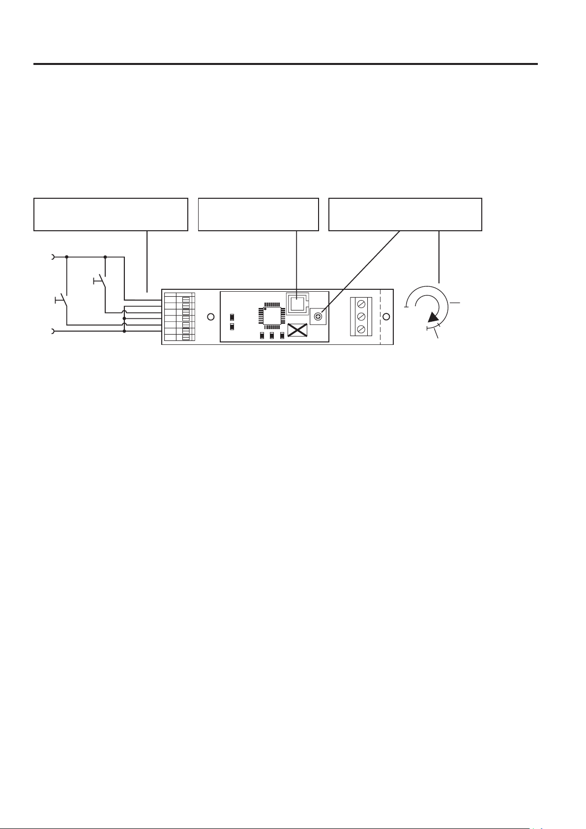
Optocoupler inputs (polarity does not
matter), switching, e.g, via buttons
VCC
Set
Reset
GND
The Voltcraft USB-programming cable (Conrad item no. 197339) is needed for data transfer. It must be connected to the J3-connection
of the multifunction timer.
Configuration by PC-software is performed in the potentiometer range of 98…100% (display by flashing LED „STAT“).
Switching of an input is explained in these operating instructions using the illustrated buttons. A pushed button is defined as a positive
level. Since these are optocoupler inputs, only one current flow is decisive for switching. The polarity is irrelevant for this.
J3: Connection of the Voltcraft
USB programming cable
J1
1
VCC
2
GND
3
SET
4
SET
RESET
5
RESET
6
SEQ
7
REL
SEQ
STAT
μ C
J3
J4
RES
SET
R3: Potentiometer (selection of the
operating mode or time setting)
J2
R3
NC
NO
COM
Timer time 10 s.....30 min
(0....98% rotating range)
PC mode (98....100% rotating area)
4

3. Overview of the Available Operating Modes
Operating modes that can be set via the PC-software: Settable time (HH : MM : SS)
Staircase Light Machine
Options:
• Activation time extension
• Early shut-down 00:00:01 - 01:30:00
• Short push of the button: Time Extension
Long push of a button (>3 s): Immediate shut-down
• Prewarning Function
• Service Function
Switch-off delay/Switch-off delay resettable 00:00:01 - 12:00:00
Switch-on delay 00:00:01 - 12:00:00
Switch-on/Switch-off delay Each 00:00:01 - 12:00:00
Switch-on/switch-off delay resettable Each 00:00:01 - 12:00:00
Alternating button (REL<->SEQ) -
Alternating button (REL->SEQ->OFF) -
Step button (REL->REL+SEQ->OFF) -
Step button with switch-off delay (REL/SEQ) Each 00:00:01 - 01:30:00
Logical operations (AND, OR, XOR) -
Power surge switch -
Presence simulation (randomly controlled) Max. 00:00:02 - 01:30:00 / min. 00:00:01 - 01:29:59
Set=>On, Reset=>Off -
On-off change Switch-on time/break each: 00:00:01 - 01:00:00
On-off change (repetitions can be set) Switch-on time/break each: 00:00:01 - 01:00:00
4. Installation of the PC Software
The installation programme is started via the file „MFT1816_Setup.exe“.
All other instructions are displayed via the installation programme.
The installation software suggests „MFT1816“ as target directory for installation and copies all the data needed into the selected directory. The
installation programme also creates a programme group „MFT1816“ under „Programmes“ and a link on the desktop.
5
5. Operation of the PC Software
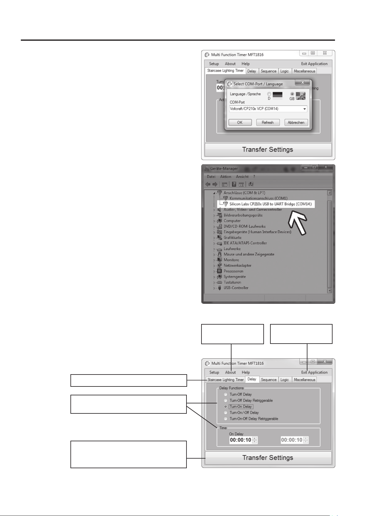
After the first programme start of the PC-software, a dialogue window appears
in which the language and communications port (COM port) are determined.
The settings in this window are saved with „OK“ and can later be changed via
„Setup“.
The correct communications interface („Silicon Labs CP210xUSB to UART Bridge…“) in Windows is found in the control panel in the device manager,
„Connections (COM & LPT)“.
The button „Refresh“ refreshes the list of the communications interfaces.
If the setting window is closed by „Cancel“, data transfer is not possible.
Selection and Transmission of a Function:
After confirmation of the language and COM port settings, the programme offers
a selection of different switching functions.
After transferring of the desired settings, the Voltcraft USB programming cable
must be disconnected from the multifunction timer. The device now performs
the desired function as described in the following section.
Selection of the switching function type via tabs
Selection of the switching function and the
associated settings
Button „Transfer Settings“ configures the
connected Multifunction timer „MFT1816“ with
the selected settings of the current tab
Programme menu of the
multifunction timer
Terminate programme
6

6. Available Functions
a) Staircase Lighting Timer
General:
• The maximum time that can be set for the staircase lighting timer by the PC software is 90 minutes.
• The service function or pre-warning function can be added optionally.
• If the button at the input „SET“ is pushed for a short time, a positive level is pending. The relay is activated at once.
When the button at the input „SET“ is released again, the relay remains activated for the set time T1.
• The push of a button at the input „RESET“ deactivates the relay output.
Optional functions (only for
staircase light machine)
Selection of the switching function type via the
tab „Staircase Lighting Timer“
Selection of the activation time in the format
„HH:MM:SS“
Selection of the switching function when the
button is pushed again
Button „Transfer Settings“ configures the
connected Multifunction timer „MFT1816“ as
staircase lighting timer
7

Options for the Staircase Light ing Timer
1. „Activation Time Extension“
If the relay is already activated, another push of the button at the input „SET“ resets the activation duration to the set value.
SET
RESET
RELAIS
2. „Early Shut-Down“
If the relay is already activated, another push of the button at the input „SET“ deactivates the relay output at once.
SET
RESET
RELAIS
<------------------------T1------------------------>
3. „Short Push of the Button: Time Extension, Long Push of the Button (>3s): Immediate Shut-Down“
If the relay is already activated, another short push of the button (<3 s) at the input „SET“ resets the set activation duration.
Long operation of the button (>=3 s) directly switches off the relay output.
SET
<------------------------T1------------------------>
<------------------------T1------------------------>
<3s
= 3s
<----------------------T1----------
RESET
RELAIS
<------------------------T1------------------------->
<------------------------T1------------------------>
<--------T1------
8

Additional functions
1. Prewarning function
Pre-warning structure:
After the end of the selected function with the set activation time T1, a 30-second pre-warning time T2 is attached. The relay swtiches off for a
short time three times at reducing intervals within a pre-warning period T2. This deactivates the relay output.
If the button at the input „SET“ is pushed during the pre-warning function, the respective associated action is performed. When the pre-warning
function selected, this is also done when the service function is ended. No other function is performed in such cases.
The push of a button at the input „RESET“ deactivates the relay output immediately.
SET
RESET
RELAIS
2. Service Function
The button at the input „SET“ must be kept pushed for >5 seconds (requirement: The relay is deactivated). Then the relay output is activated for
the duration of 60 minutes.
Pushing the button again during the 60 minutes deactivates the relay output.
If the „Pre-warning function“ is set additionally, the warning sequence is added before the end of the time as described before.
After termination or end of the service function, the assembly is operational again as staircase light machine.
The push of a button at the input „RESET“ deactivates the relay output immediately.
SET
RESET
RELAIS
<------------------------------T1------------------------------->
>5s
<--------------------------------------------60 Min.-------------------------------------------->
<-------15s------->
Pause
<------------------------T2------------------------->
Pause
<---10s--->
Pause
<5s>
SET
RESET
RELAIS
SET
RESET
RELAIS
>5s
<--------------------------------------------60 Min.-------------------------------------------->
>5s
<--------------------------------------------60 Min.-------------------------------------------->
9

b) Delay Functions
1. „Switch-Off Delay“
If the button at the input „SET“ is pushed for a short time, a positive level is pending. The relay is activated at once.
When the button at the input „SET“ is released again, the relay remains activated for the set deactivation delay T1. If the button at the input „SET“
is pushed again during this time, this does not affect the set deactivation delay (timer time T1).
The push of a button at the input „RESET“ deactivates the relay output immediately.
SET
RESET
RELAIS
2. „Switch-Off Delay Resettable“
If the button at the input „SET“ is pushed for a short time, a positive level is pending. The relay is activated at once.
When the button at the input „SET“ is released again, the relay remains activated for the set deactivation delay T1. If the button at the input „SET“
is pushed again during this time, this will start the set deactivation delay T1 again.
The push of a button at the input „RESET“ deactivates the relay output immediately.
SET
RESET
RELAIS
SET
RESET
<-------T1------->
<-------T1------->
<-------T1------->
<-------T1------->
RELAIS
3. „Switch-On Delay“
If the button at the input „SET“ is pushed, a positive level is pending. The relay is only activated if the button is kept pushed for longer than the
activation delay time set as T1.
The relay is deactivated at once if the button at the input „SET“ is released.
The push of a button at the input „RESET“ deactivates the relay output immediately.
SET
RESET
RELAIS
<-------T1------->
<-------T1------->
<-T1-> <-T1->
<-------T1------->
<-------T1------->
10

4. „Switch-On/Switch-Off Delay“
If the button at the input „SET“ is pushed, a positive level is pending and the set switch-on delay T1 will start at once. After the end of T1, the relay
is activated for the duration of switch-off delay T2.
If the button at the input „SET“ is pushed again during this time (T1 or T2), this does not affect the switch-on/switch-off delay.
The push of a button at the input „RESET“ deactivates the relay output immediately.
SET
RESET
RELAIS
<-------T1------->
SET
RESET
RELAIS
<-------T1------->
5. „Switch-On/Switch-Off Delay Resettable“
If the button at the input „SET“ is pushed, a positive level is pending and the set switch-on delay T1 will start at once. After the end of T1, the relay
is activated for the duration of switch-off delay T2.
If the button at the input „SET“ is pushed during this time (T1 or T2), the respective set activation or deactivation delay will start again at once.
The push of a button at the input „RESET“ deactivates the relay output immediately.
SET
RESET
<-------------T2------------->
<-------T1------->
<-------T1------->
<-------------T2------------->
<-------------T2-------------><-------------T2------------->
RELAIS
SET
RESET
RELAIS
<-------------T1------------->
<-------------T1------------->
<-------------T1------------->
<-------------T1------------->
<-------------------T2------------------->
<-------------------T2------------------->
<-------------------T2------------------->
<-------------------T2------------------->
11

c) Sequence Functions
1. „Alternating Button (REL<->SEQ)“
Operation of the button at the input „SET“ toggles the relay output and the sequence output („OFF“ <-> „ON“).
The function is NOT started with the input „SET“ but is activated by transferring the function on the multifunction transmitter!
The function starts with activated relay output and deactivated sequence output.
First operation of the button at the input „SET“ => relay output deactivated, sequence output activated.
Second operation of the button at the input „SET“ => relay output activated, sequence output deactivated, etc.
Only when a button is pushed at the input „RESET“ both outputs will be deactivated.
After a reset, the function is re-started if the button at the input „SET“ is pushed (starting with activated relay outputs).
SET
RESET
RELAIS
SEQUENZ
2. „Alternating Button (REL->SEQ->OFF)“
Operation of the button at the input „SET“ toggles the condition of the relay outputs in the order „Relay on“ -> „Sequence on“ -> „Completely off“
(starting with activated relay output).
First operation of the button at the input „SET“ => relay output activated, sequence output deactivated.
Second operation of the button at the input „SET“ => relay output deactivated, sequence output activated.
Third operation of the button at the input „SET“ => relay and sequence output are deactivated, etc.
When a button is pushed at the input „RESET“ both outputs will be deactivated. After a reset, the function is re-started if the button at the input
„SET“ is pushed (starting with activated relay outputs).
SET
RESET
RELAIS
SEQUENZ
12

3. „Step Button (REL->REL+SEQ->OFF)“
Operation of the button at the input „SET“ toggles the relay output on, its sequence output on and then both outputs off in sequence.
First operation of the button at the input „SET“ => relay output activated, sequence output deactivated.
Second operation of the button at the input „SET“ => relay output remains activated, sequence output is activated.
Third operation of the button at the input „SET“ => relay and sequence output are deactivated, etc.
When a button is pushed at the input „RESET“ both outputs will be deactivated. After a reset, the function is re-started if the button at the input
„SET“ is pushed (starting with activated relay outputs).
SET
RESET
RELAIS
SEQUENZ
4. „Step Button with Switch-Off Delay“
Operation of the button at the input „SET“ toggles the switching condition of the device in the order „Relay on“ -> „Sequence on“ -> „Completely
OFF“ with adjustable deactivation delay (starting with activated relay output).
First operation of the button at the input „SET“ => relay output is activated for the set time T1.
Second operation of the button at the input „SET“ => sequence output is activated for the set time T2.
Third operation of the button at the input „SET“ => relay and sequence output are deactivated, etc.
When a button is pushed at the input „RESET“ both outputs will be deactivated. After a reset, the function is re-started if the button at the input
„SET“ is pushed (starting with activated relay outputs).
SET
RESET
RELAIS
SEQUENZ
SET
RESET
RELAIS
<-------------T1------------->
<-------------T1------------->
<-------------------T2------------------->
<-------------T1------------->
<---------------T2---------
<-------------------T1------------------->
SEQUENZ
<-------------T2-------------> <-------------T2------------->
13

d) Logical Operations (AND, OR, XOR) of the Inputs „SET“ and „RESET“
Logical operation Input 1 („SET“) Input 2 („RESET“) Relay
AND OFF OFF OFF
OFF ON OFF
ON OFF OFF
ON ON ON
OR OFF OFF OFF
OFF ON ON
ON OFF ON
ON ON ON
XOR OFF OFF OFF
OFF ON ON
ON OFF ON
ON ON OFF
The inputs „SET“ and „RESET“ can be used as logical inputs for the operation functions „AND“, „OR“ or „XOR“.
The signals must pend for at least 50 ms („Debouncing time“) so that the output relay is switched accordingly.
14

e) Other Functions
1. „Power Surge Switch“ (On/Off Switch)
If the button at the input „SET“ is pushed, this causes the relay to toggle („ON“ <-> „OFF“).
The push of a button at the input „RESET“ deactivates the relay output immediately.
SET
RESET
RELAIS
2. „Presence Simulation (Randomly Controlled)“
If the button at the input „SET“ is pushed, a positive level is pending and the switch between switch-on delay (T1) and break time (T2) takes place
at once, starting with the activation time T1. The two times are random values between the minimum and maximum time entered by PC software.
If the button at the input „SET“ is pushed while the function is already running, this has no effect on the relay output.
The push of a button at the input „RESET“ deactivates the relay output immediately.
SET
RESET
RELAIS
SET
RESET
RELAIS
3. „Set => On, Reset => Off“
If the button at the input „SET“ is pushed, the relay is activated at once.
The push of a button at the input „RESET“ deactivates the relay output immediately.
RESET
-------->
SET
<-T1->
<-------------------T1------------------->
<-T2->
<-------T1------->
<-------T2------->
<-------------------T2------------------->
<-------------T1------------->
<-----------T2-----
<-T1-> <-T2->
<---T1--
RELAIS
15

4. „On-Off Toggle“ Switch (Activation and Break Time can be set independently)
While the button at the input „SET“ is kept pushed, the relay is activated or deactivated according to the respective switch-on time (T1) and break
time (T2) set, starting with the activation time T1.
Releasing the button at the input „SET“ cancels the function.
The push of a button at the input „RESET“ deactivates the relay output immediately.
SET
RESET
RELAIS
SET
RESET
RELAIS
5. „On-Off Toggle“ with Setting Repetitions (Activation and Break Time can be set independently)
If the button at the input „SET“ is pushed, a positive level is pending and the relay is activated at once. The relay is activated or deactivated
according to the respective switch-on time (T1) and break time (T2) set, starting with the activation time T1.
The number of repetitions can be set by PC software (maximum number of repetitions = 255).
If the button at the input „SET“ is pushed while the function is already running, this has no effect on the relay output.
The push of a button at the input „RESET“ deactivates the relay output immediately.
SET
<-T1-> <-T1-> <-T1-> <-------T2------->
<-------------T1------------->
<-------T2------->
<-------T2------->
<-------T2------->
<-------------T1------------->
<-------T2------->
RESET
RELAIS
SET
RESET
RELAIS
<-------T1------->
<-------T1------->
<-------------T2-------------> <-------------T2------------->
<-------------T2------------->
<-------T1------->
<-------T1------->
<-------------T2------------->
16

http://www.conrad.com
Legal Notice
These operating instructions are a publication by Conrad Electronic SE, Klaus-Conrad-Str. 1, D-92240 Hirschau (www.conrad.com).
All rights including translation reserved. Reproduction by any method, e.g. photocopy, microfilming, or the capture in electronic data processing systems
require the prior written approval by the editor. Reprinting, also in part, is prohibited.
These operating instructions represent the technical status at the time of printing. Changes in technology and equipment reserved.
© Copyright 2013 by Conrad Electronic SE.
V2_0313_01
 Loading...