

Page 1

“Electronic Start” Learning Package
Item-No. 19 22 30
Version 07/09
OPERATING INSTRUCTIONS
These Operating Instructions accompany this product. They contain important information on setting up
and using it. You should refer to these instructions, even if you are buying this product for someone
else.
Please retain these Operating Instructions for future use!
A list of the contents can be found in the Table of contents, with the corresponding page number, on
page 2.
Page 2

Table of contents
1 Getting started ....................................................................................................................3
2 First tries with LEDs............................................................................................................9
2.1 LED with series resistor ..................................................................................................9
2.2 Current direction ............................................................................................................11
2.3 Amperages ....................................................................................................................12
2.4 Signal lamp with pushbutton switch ..............................................................................13
3 LED circuit technology......................................................................................................15
3.1 Diode threshold voltage ................................................................................................15
3.2 Series connection ..........................................................................................................17
3.3 Little energy – a lot of light ............................................................................................19
3.4 Parallel connection ........................................................................................................20
3.5 Plays of colour ..............................................................................................................22
3.6 Flashlight ......................................................................................................................23
4 Test instruments with LEDs ............................................................................................24
4.1 Cable tester ..................................................................................................................24
4.2 Water detector ..............................................................................................................25
4.3 Alarm device..................................................................................................................26
4.4 Polarity tester ................................................................................................................27
4.5 Battery tester ................................................................................................................28
4.6 LED as temperature sensor ..........................................................................................29
5 Transistor circuits ............................................................................................................31
5.1 Amplification ..................................................................................................................31
5.2 Follow-up control ..........................................................................................................32
5.3 Touch sensor ................................................................................................................33
5.4 LED as light sensor........................................................................................................34
5.5 Constant brightness ......................................................................................................35
5.6 Temperature sensor ......................................................................................................36
5.7 On and off......................................................................................................................37
5.8 LED blinker ....................................................................................................................39
2
Page 3
1 Getting started
This learning package is an easy introduction to electronics. The following is a presentation of
the components.
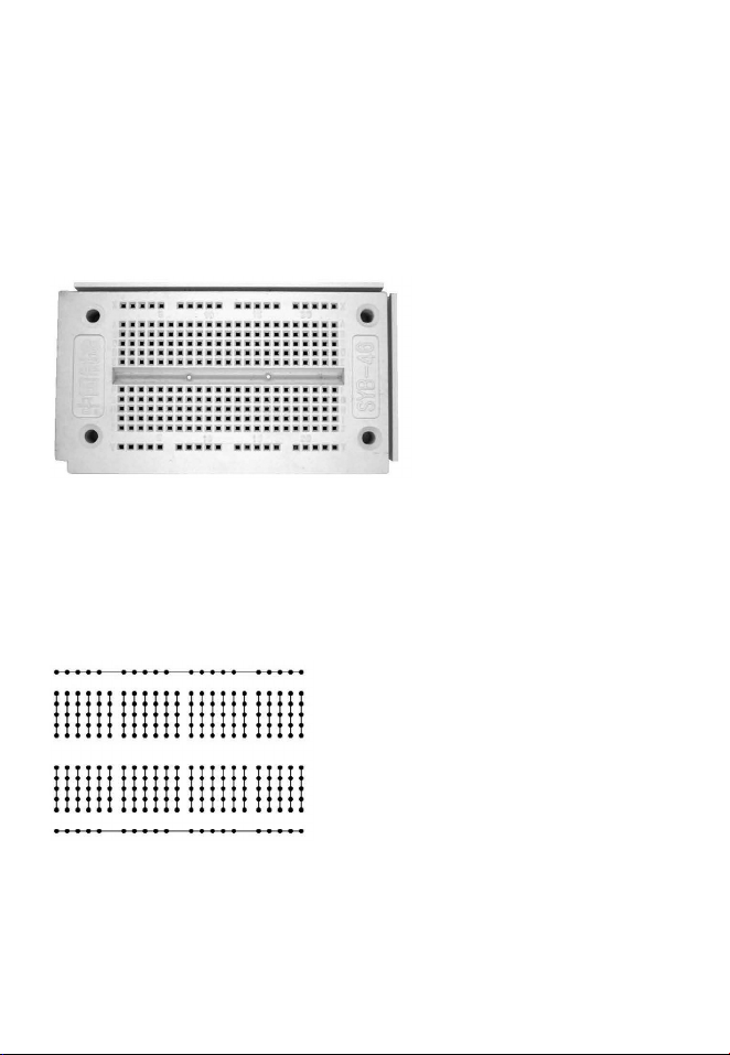
Patch board
All experiments are conducted on a laboratory experimenting board.
The patch board with a total of 270 contacts in a 2.54-mm grid ensures safe connections of the
integrated circuits (ICs) and the individual components.
The patch board has 230 contacts in the middle section which are connected conductively
by vertical lines in groups of five. In addition, there are 40 contacts for the power supply on the
upper and lower edges consisting of two horizontal contact spring strips with 20 contacts each.
The patch board thus has two independent supply rails. Figure 1.2 shows all internal connections.
You can see the short contact rows in the middle section and the long supply rails on the edges.
3
Figure 1.1: The experimenting board
Figure 1.2: The internal contact rows
Page 4
Inserting components requires a good amount of force. The connecting wires might bend easily.
Therefore, make sure to insert the connecting wires exactly from the top. Use a pair of tweezers
or a small pair of pliers. Hold the connecting wires as closely as possible to the patch board and
press them down in a vertical movement. Proceed in the same way to insert sensitive connecting
wires such as the tinned ends of battery clips.
For your experiments, you require different lengths of wire which must be cut off from the provided
jumper wire. To strip the wire ends, it is a proven method to first cut into the insulation around the
wire using a sharp knife.
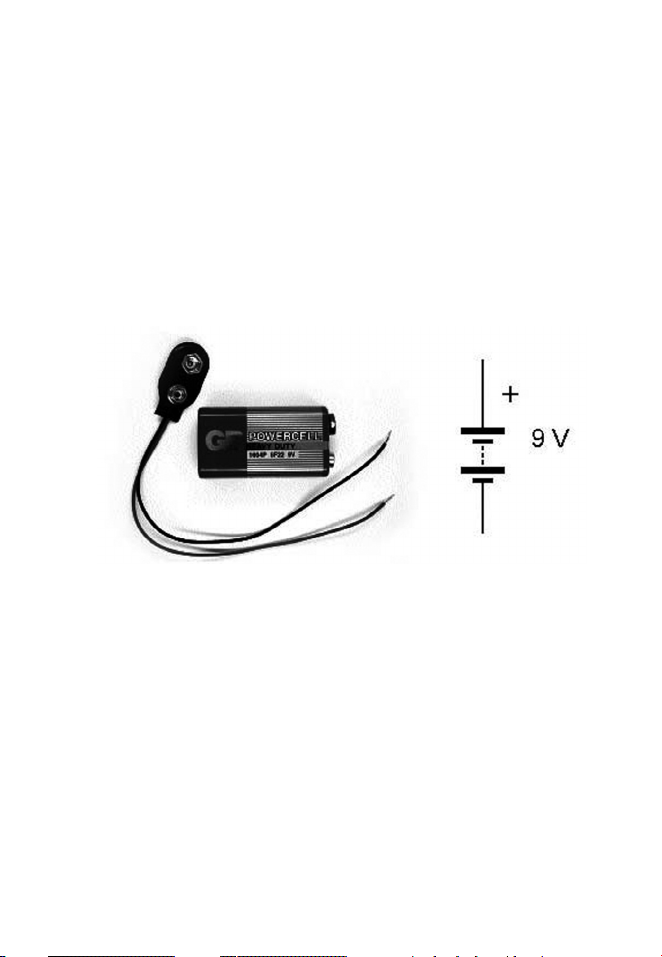
Battery
The following overview shows the components as they really look and the symbols used in circuit diagrams. The battery can be replaced by e.g. a power supply.
You should not use alkali batteries or rechargeable batteries. Only use zinc-carbon batteries.
Although alkali batteries have a longer lifetime, they might – just like rechargeable batteries –
supply high currents above 5 A e.g. in case of a short circuit, which can cause the thin wires or
the battery itself to heat up considerably. The current supplied by a zinc-carbon battery during
a short circuit is usually below 1 A. This can destroy sensitive components but there is no
danger of fire.
The provided battery clip has a connecting cable with a flexible wire. The cable ends are stripped and
tinned. Therefore, they are rigid enough to be inserted into the contacts of the patch board. However,
they can lose shape if plugged in frequently. For this reason, we recommend leaving the battery
wires connected and just removing the clip from the battery.
4
Figure 1.3: Battery and battery diagram symbol
Page 5
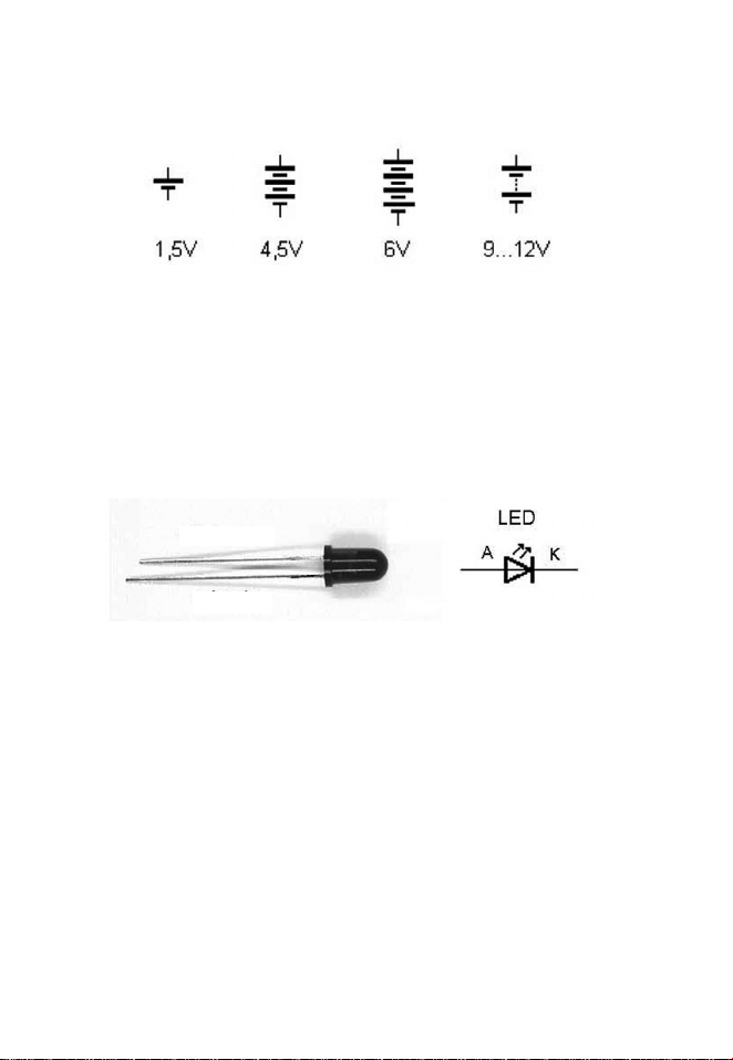
A single zinc-carbon or alkali cell has a voltage of 1.5 V. Several cells are connected in series
in one battery. Accordingly, the symbols show the number of cells in a battery. For higher voltages, it is common practice to indicate the middle cells by a dotted line.
LED
The learning package includes two red LEDs, one green LED and one yellow LED. The polarity
of all LEDs must always be observed. The negative connection is called cathode. It is at the shorter connecting wire. The positive connection is called anode. The cup-shaped holder that holds
the LED crystal at the cathode is visible inside the LED. The anode connection is connected with
an extremely thin wire to a contact at the top of the crystal. Caution! Unlike light bulbs, LEDs
must never be directly connected to a battery. A series resistor is always required.
5
Figure 1.4: Diagram symbols for different batteries
Figure 1.5: LED
- Cathode
+ Anode
Page 6
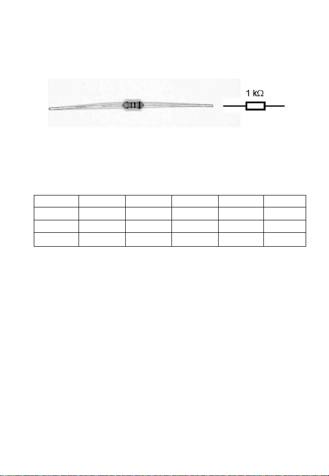
Resistors
The resistors included in the learning package are carbon film resistors with tolerances of ±5 %.
The resistor material is applied on a ceramic rod and covered with a protective layer. Rings of
different colours indicate the resistor type. The resistance value and the accuracy class are
indicated.
Resistors with a tolerance of ±5 % are in the E24 list. Every decade includes 24 values with
about the same distance to the neighbouring values.
Table 1.1: Resistance values according to the E24 standard list
1,0 1,2 1,3 1,4 1,5 1,6
1,8 2,0 2,2 2,4 2,7 3,0
3,3 3,6 3,9 4,3 4,7 5,1
5,6 6,2 6,8 7,5 8,2 9,1
Begin reading the colour code from the ring closest to the edge of the resistor. The first two
rings represent digits whereas the third ring is a multiplier for the resistance value in ohms. The
fourth ring represents the tolerance.
6
Figure 1.6: Resistor
Page 7

Table 1.2: Resistance colour codes
Colour Ring 1 Ring 2 Ring 3 Ring 4
1. digit 2. digit Multiplier Tolerance
Black 0 1
Brown 1 1 10 1 %
Red 2 2 100 2 %
Orange 3 3 1.000
Yellow 4 4 10.000
Green 5 5 100.000
Blue 6 6 1.000.000
Purple 7 7 10.000.000
Grey 8 8
White 9 9
Gold 0,1 5 %
Silver 0,01 10 %
A resistor with the ring sequence yellow, purple, brown and gold has 470 ohms and a tolerance
of 5 %. The learning package includes two resistors of each of the following values:
100 Ω Brown, black, brown
220 Ω Red, red, brown
330 Ω Orange, orange, brown
470 Ω Yellow, purple, brown
1 kΩ Brown, black, red
10 kΩ Brown, black, orange
100 kΩ Brown, black, yellow
7
Page 8
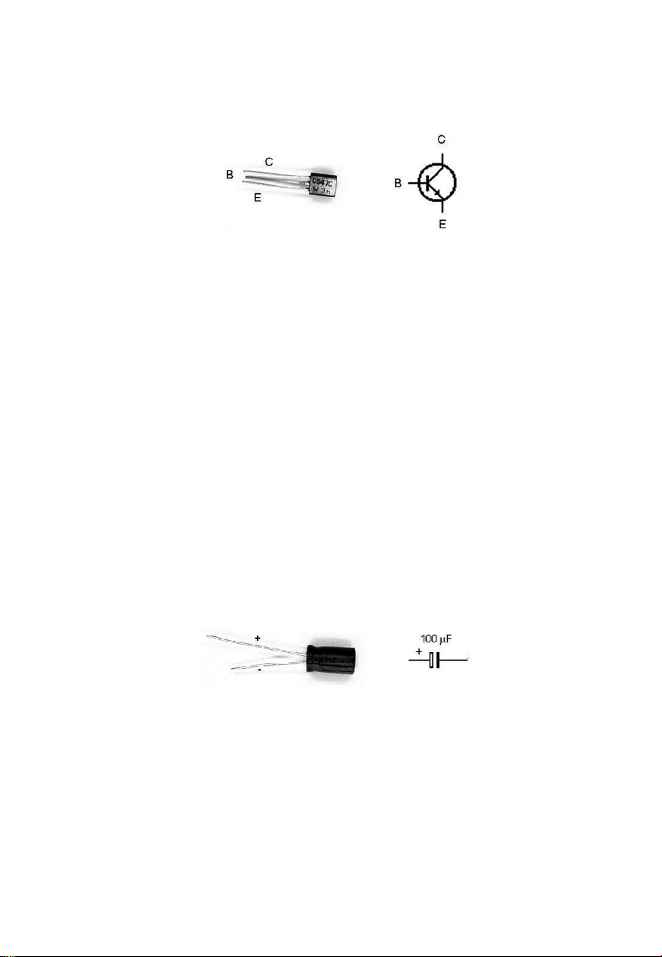
Transistors
Transistors are components used for the amplification of small currents. The used BC547 resistors are silicon NPN transistors.
The connections on the transistor are called emitter (E), basis (B) and collector (C). The basis
connection for both transistors is in the middle. Looking at the label with the connection pointing
downwards, the emitter is on the right.
Capacitor
The capacitor is another important electronic component. A capacitor consists of two metal surfaces and an insulating layer. When electric voltage is applied, an electric field in which energy is
stored builds up between the two capacitor plates. A capacitor with a big plate surface and a
small distance between the plates has a high capacity, i.e. it stores a lot of energy when voltage
is applied. The capacity of a capacitor is measured in Farad (F).
Electrolytic capacitors reach high capacities. The insulation consists of a very thin layer of aluminium oxide. The electrolytic capacitor contains a fluid electrolyte and aluminium foil with a big
surface. Voltage must only be applied in one direction. In the wrong direction, leakage current
will gradually reduce the insulating layer and finally destroy the component. The negative
terminal is indicated by a white stripe and the connecting wire is shorter.
8
Figure 1.7: Transistors
Figure 1.8: Electrolyte capacitor
Page 9
2 First tries with LEDs
You can take a battery and a small light bulb and try different things until the bulb lights up. You
should not try the same with an LED as it will be destroyed quickly if connected directly to a battery.
You have to proceed a bit more systematically: Observe the correct voltage, the right polarity, and
use a suitable series resistor. It is not really difficult. Try out the circuits described below to become
familiar with working with LEDs.
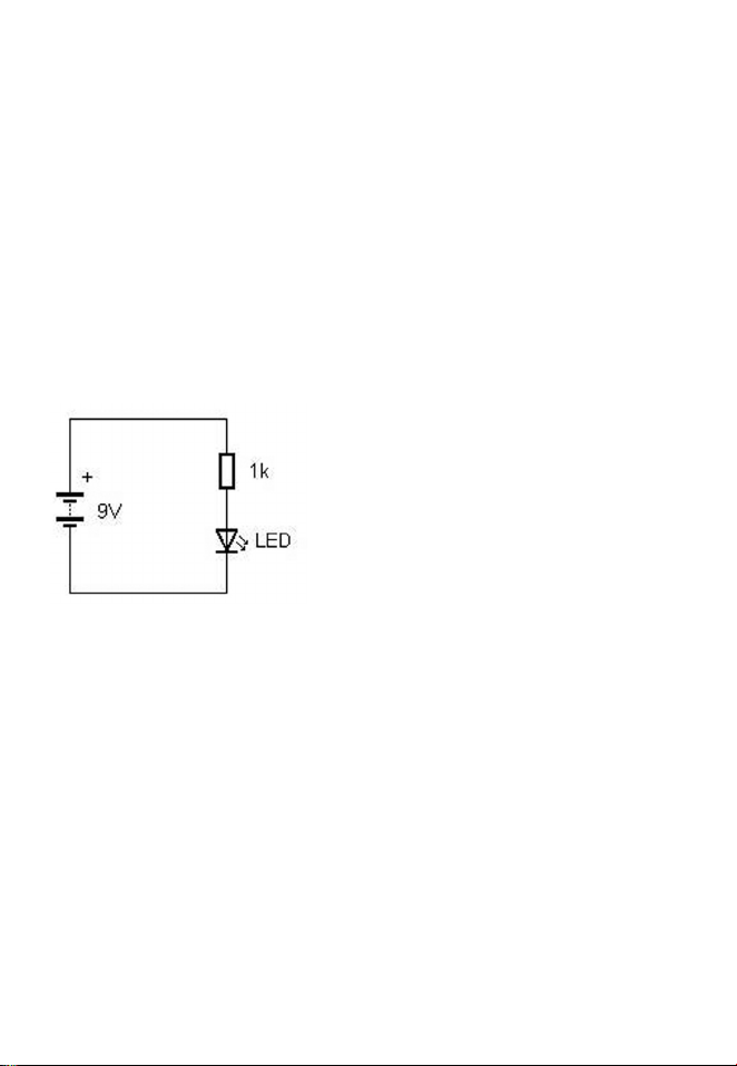
2.1 LED with series resistor
Set up your first circuit with a battery, an LED and a series resistor. Use a red LED and a 9V
battery. Take the hightest resistance value (1 kΩ = 1000 Ω, colours: brown, black, red) from
the learning package to be on the safe side in terms of LED current. Figure 2.1 shows the circuit as a circuit diagram.
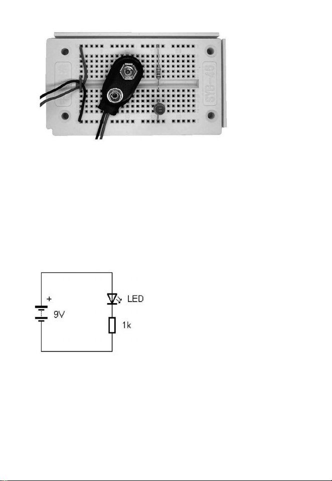
Use the patch board to set up the circuit. Connect the upper supply rail with the positive terminal
of the battery, i.e. with the red connector on the battery clip. Connect he lower supply rail accordingly to the black clip connector, i.e. to the negative terminal of the battery. The actual circuit will
resemble the circuit diagram so that troubleshooting should not pose any problems. Bend the
connecting wires of the LEDs and the resistors so that they fit into the contacts. Some connecting
wires were shortened in this test setup for better illustration. You should, however, leave the
wires uncut to ensure that the components can be used for all other experiments as well.
9
Figure 2.1: Circuit diagram of LED with series resistor
Page 10
The first try will probably be successful. The LED lights up brightly. If not, look for the mistake.
Any interruption of the circuit prevents current flow. Therefore, check all lines and the position
of the components on the patch board. As another possible problem, the LED might have been
inserted the wrong way, or the battery is empty. You will notice, however, that even very old
batteries still provide enough power for the LED to light up weakly.
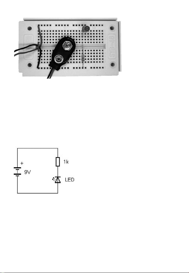
Try a different layout. Swap the LED and the resistor. The current will then flow through the LED
before flowing through the resistor. The effect is the same as in the first case, however. The
only important thing is that all three components are connected in a closed circuit.
10
Figure 2.2: Setup on the patch board
Figure 2.3: Swapped components
Page 11
2.2 Current direction
Turn the LED so that the anode is connected to the negative terminal of the battery. There is no
light! This means that current can only flow through the LED in one direction. The forward
direction is the current direction from anode to cathode, with the anode connected to the positive terminal of the battery and the cathode to the negative terminal. In reverse direction, the LED
is blocked. A diode is like an electric valve. It only lights up when current is let through. Figure
2.5 shows the LED with reverse direction. It cannot light up.
The arrows in the LED circuit diagram in figure 2.6 indicate the direction of current. The direction
of current as well as the designation plus and minus was defined arbitrarily in history. This
means, current always flows from the positive terminal of the battery through the load to the
negative terminal of the battery. Today, it is common knowledge that negatively charged electrons inside the wires move exactly opposite to the direction indicated by the arrows in figure 2.6.
There are, however, positive charge carriers as well, as e.g. in fluids, that move with the direction of the current. Even inside the LED itself there are negative and positive charge carriers.
11
Figure 2.4: LED and resistor swapped
Figure 2.5: LED in reverse direction
Page 12
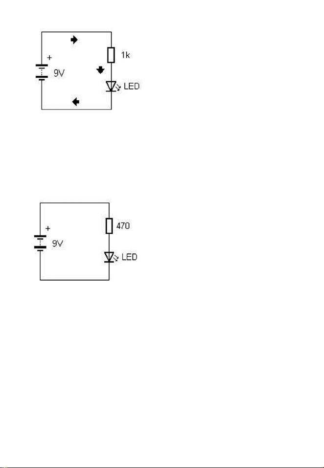
2.3 Amperages
Instead of the 1-kΩ resistor, insert a smaller resistor of 470 Ω(yellow, purple, brown). The LED
lights up noticeably brighter. This indicates higher current. The rule is: The higher the resistance, the lower the current. More accurate calculations are stated below.
Test the brightness of all LEDs with resistors of 1 kΩ (brown, black, red), 470 Ω (yellow, purple,
brown) and 330 Ω (orange, orange, brown) each. However, do not use a resistance lower than
330 Ω, as this might result in a current too high for the circuit with a 9-V battery and consequently
harm the LED.
12
Figure 2.6: Direction of current
Figure 2.7: More brightness with a lower series resistance
Page 13

The used LEDs are approved for continuous current of 20 mA. The table below shows that the
actual current of the used LED depends on the series resistor. In some cases, the approved current is slightly exceeded. If this happens for a short time, it does not constitute a problem. If overloaded for a long period of time, the LEDs wear out faster and lose their luminosity.
Table 2.1: LED current at a battery voltage of 9 V
Resistance red LED yellow LED green LED
330 Ω 21.4 mA 21.1 mA 20.8 mA
470 Ω 15.1 mA 14.9 mA 14.7 mA
1.000 Ω 7.2 mA 7.1 mA 7.0 mA
2.4 Signal lamp with pushbutton switch
Make a simple pushbutton switch using stripped jumper wire as illustrated in figure 2.9. When
opened, the switch represents an interruption of the circuit. When the switch is pressed, the two
contacts are connected and the circuit is closed. The elasticity of the wire disconnects the contact when you let go of the switch. Consequently, the LED within the circuit only lights up as
long as the switch is pressed.
13
Figure 2.8: 470 Ω series resistance
Page 14

This setup can be used as a signal lamp for various purposes. In principle, this switch can also
be used to transmit complex messages by Morse code. Admittedly, sending messages in Morse
code is a little old-fashioned and not as comfortable as an e-mail or a phone call. However, using
Morse code with an LED can be a delightful way of communication. With some practice, information can be exchanged over a distance of up to 100 m with almost nobody else being able to
listen in.
14
Figure 2.10: Circuit with switch
Figure 2.9: Setup of a switch using wire
Page 15

3 LED circuit technology
It is easy to set up a given circuit using the recommended components. Whoever really wants
to master circuit technology, however, should become familiar with theoretical aspects in order
to be able to calculate required resistances in a circuit. The chapter provides the necessary
aspects and the corresponding experiments. Combine theory with practice. Calculate and test
your own circuits!
3.1 Diode threshold voltage
In comparison with a light bulb, an LED seems to behave strangely. Not only does the current
flow in one direction – as opposed to a light bulb which can be connected with either polarity –,
the supply voltage in forward direction is of great importance as well. A small light bulb with 6 V,
100 mA shows great tolerance towards the actual supply voltage. Already approx. 1 V is
enough to cause a weak, dark red glow. At the rated voltage, a bright yellowish-white light is
produced. If you try a higher voltage for a very short time, the light becomes glaring white. Even
twice the rated current of 12 V does not destroy the light bulb immediately, but after a couple of
seconds or minutes.
LEDs show a completely different behaviour. The normal voltage of a red LED supplied with 10 to
20 mA is approximately 1.8 V. If the voltage is raised by only 0.5 V to 2.3 V, the LED inevitably
burns out. On the other hand, the LED does not light up at all if the voltage is reduced by only half
a volt. If a higher voltage is applied, a resistor makes sure that the correct voltage is automatically
set.
Now try to operate a red LED without a resistor directly on a 1.5-V cell. Only because the voltage
is at the lower limit, you can omit the series resistor in this case.
15
Page 16

The red LED will light up but only show a very weak light. Now insert the green LED. Result: It
does not light up! As a matter of fact, virtually no current flows through the green LED. The characteristics of the yellow LED are between the red and the green LED. 1.5 V might produce a very
weak light at best.
What current flows with what voltage? This question is answered by the characteristic curve of
a component. Figure 3.3 shows the measured characteristic curve of the red and the green
LED in a common diagram. In both cases, you can see that a noticeable amount of current only
flows above a minimum voltage or “threshold voltage”. With increasing voltage, the current
increases as well. Measurements were stopped at the approved maximum of 20 mA. It is,
however, easy to images the progression of the curves. Only a small increase in voltage leads
to a significant increase in current, which can easily destroy the LED.
16
Figure 3.1: At the lower voltage threshold
LED, red
Figure 3.2: Direct connection of an AA battery
Page 17

The diagram clearly shows the different threshold voltages of the red and the green LED. Now it is
obvious why the red LED lights up weakly at 1.5 V whereas the green LED does not light up at all.
When LED circuits are dimensioned, usually series resistors are used to set a specific diode current. If you assume a normal operating current of 20 mA, the resulting voltages for the different
LED types are as shown in table 3.1.
Table 3.1: Typical LED voltages
LED colour Voltage at 20 mA
Red 1.9 V
Yellow 2.1 V
Green 2.2 V
3.2 Series connection
When the battery voltage is sufficient (e.g. 9 V), two or more LEDs can be connected in series.
The forward voltages of the diodes are added, so that less voltage is present at the series resistor.
A red and a green LED have a diode current of 10 mA and a voltage of 1.9 V + 2.2 V = 4.1 V. The
voltage at the series resistor is consequently 9 V - 4.1 V = 4.9 V. To set a current of 10 mA, the
resistor must be adjusted accordingly.
17
Figure 3.3: LED characteristic curves
red
green
Page 18

R = U/I
R = 4.9 V/10 mA
R = 490 Ω
The calculation often results in a resistance value outside the standard values.
In such a case, use the next smallest standard value. In this case, the value is 470 Ω. The current
is increased insignificantly. In fact, the voltage ratio hardly changes due to the steep characteristic
curve of the diode.
18
Figure 3.4: LEDs in series connection
Figure 3.5: Red and green LED in series connection
red
green
Page 19

3.3 Little energy – a lot of light
Connecting several LEDs in series is often more efficient as less energy is transformed into
useless heat in the series resistor. Thus, you have to try to keep the voltage drop at the series
resistor as low as possible. Figure 3.6 shows the possible dimensioning with three LEDs (red,
yellow, green). The combined diode voltage is 1.8 V + 2.1 V + 2.2 V = 6.1 V. The voltage drop
at the series resistor is 2.9 V. For a current of 20 mA, a resistance of 145 Ω is required. Even at
220 Ω there is still a good amount of brightness. Instead of 20 mA, the resulting current is
15 mA which results in quite a long operating time with a 9-V battery.
19
Figure 3.6: Series connection with three LEDs
Figure 3.7: All colours in series
red
green
yellow
Page 20

3.4 Parallel connection
If two or more loads are to be operated on a common current source, there are generally two possibilities: a parallel circuit or a serious circuit.
When two loads are connected in series (fig. 3.8, right), the same current flows through
them. However, the loads only get part of the battery voltage. This circuit was
used in the preceding section. With LEDs in a series circuit, the same current flows through
every LED. This does not allow you to individually adjust the current. Different LEDs do not
have the brightness at the same current.
If both loads are connected in parallel (fig. 3.8, left), they are supplied the same voltage. The wiring
of a vehicle is an example. The battery has a voltage of 12 V, as do all lamps. This means they
have to be connected in parallel. When connected in parallel, the series connection of LED and
series resistor combined has to be regarded as one load. Due to the differences in LED voltage, it
is not possible to use a common series resistor. The differences in brightness can be balanced
using different series resistors.
For every single LED, the maximum current and the lowest admissible series resistance has to
be observed according to the supply voltage. Table 3.2 provides an overview of the minimum
resistances.
20
Figure 3.8: Parallel and series connection
Page 21

Table 3.2: Minimum resistances at different supply voltages
LED 3 V 6 V 9 V 12 V
Red, 20 mA, 1.8 V 60 Ω 210 Ω 360 Ω 510 Ω
Yellow, 20 mA, 2.1 V 45 Ω 195 Ω 345 Ω 495 Ω
Green, 20 mA, 2.2 V 40 Ω 190 Ω 340 Ω 490 Ω
Fig. 3.9 shows the example of a parallel connection of three LEDs with a series resistor each. The
yellow LED should be supplied with more current to balance its brightness which is not perceived
as strong. The circuit diagram shows the measured currents for every LED.
The currents add up to a total of almost 30 mA.
21
Figure 3.9: Parallel connection with three LEDs
greenyellowred
Figure 3.10: Each LED has an individual resistor
Page 22

3.5 Plays of colour
Set up a circuit with a 9-V battery, a green LED and a 1-kΩ series resistor, as described in
chapter 2. The green LED lights up as expected. Now connect a red LED to the green LED in
parallel, i.e. cathode to cathode and anode to anode. Now the red LED lights up but the green
LED goes out. This might be surprising, as a single switch or contact is enough to achieve a
switching function.
The function of the switch is explained by the different characteristic curves of the two LEDs.
When connected in parallel, both have the same voltage. At the same voltage, however, significantly more current flows through the red LED than through the green LED. When the red LED
is connected, the common voltage is reduced to such an extent that almost no current flows
through the green LED anymore.
22
Figure 3.11: Different LEDs in parallel connection
Figure 3.12: Switching the colour with a pushbutton switch
red
green
Page 23

3.6 Flashlight
A capacitor stores electrical energy. The xenon flash lamp of a camera, for example, uses a
100 µF electrolyte capacitor which is charged to 400 V and then discharges 8 wattseconds, a
great amount of energy.
An LED flash has to be constructed a bit more modestly since the LED cannot withstand as
much energy. Charge the 47-µF electrolytic capacitor with a voltage of 9 V. Due to the low voltage, the flash energy is only about 2 mWs. Only a very low charging current is required so a
charging resistor of 100 kΩ is sufficient. The electrolytic capacitor is sufficiently charged after
about five seconds. Now press the pushbutton. The LED lights up quickly and then goes out
almost completely. The LED then emits a very weak light because of the low current that still
flows through the charging resistor.
23
Figure 3.13: LED flash with electrolytic capacitor
Figure 3.14: Flash
Page 24

4 Test instruments with LEDs
It is often the small and simple devices that facilitate our work. Simple test instruments with LEDs
as indicators save power and work effectively. The advantage of an LED is the brightness reached
with very low currents and the voltage threshold which can be used as reference voltage.
4.1 Cable tester
When checks of electrical devices or installations are carried out, it is often necessary to check
the individual connections. The following test instrument lets a test current flow through the line.
The LED lights up when there is a connection.
This way, you can look for bad contacts or interrupted lines.
Set up a continuity tester on the patch board and have two long cable protrude from it as test
cables.
24
Figure 4.1: Continuity tester with LED
Figure 4.2: Test instrument with test cables
Page 25

The LED does not only light up in case of full continuity, but also when loads with a certain
resistance close the circuit. Thus, you can use this tester to check light bulbs etc. The DC resistance of a transformer is also low enough to make the LED light up brightly. With faulty power
supplies, usually the internal thermal fuse is interrupted. In such a case, there is no continuity
between the two pins of the power plug. Also check other components such as LEDs or resistors. LEDs only show continuity in one direction and then light up by themselves. Resistors
show less brightness depending on the resistance value.
4.2 Water detector
The continuity tester described in the previous section can also be used to measure the conductivity of water or other fluids. If you hold the two wires into water, the LED should also light up
dimly. The conductivity is increased significantly if you add some salt. Lemon juice or another acid
will cause the same effect. As soon as there is a flowing current, little gas bubbles are generated
around the wires. The chemical electrolytic reaction also corrodes the wire surface. For more
extended experiments, electrodes made of carbon or graphite are suitable as they do not corrode.
Use e.g. pencil leads or carbon sticks from old batteries.
Apart from interesting conductivity experiments in fluids, there are also practical applications.
For example, you can construct warning devices for leaking water, or rain detectors. The circuit
is also suitable as a moisture sensor for flower pots. If you stick the test wires into the soil, the
LED brightness indicates the degree of humidity.
25
Figure 4.3: Water in the circuit
Water
Page 26

4.3 Alarm device
To set up a theft or burglary alarm, mechanically or magnetically activated contacts on doors or
windows are used. The alarm is triggered, for example, when a window is opened. The simplest
way is to install a thin wire which is severed in case of an alarm. If someone tries to disable the
alarm by cutting the wire, the alarm is triggered as well.
In the simplest case, the current loop can be monitored by an LED. In idle state however, the
LED should be off in order not to attract additional attention. The LED should only light up when
the wire is severed. Figure 4.4 shows the circuit. As long as the monitoring circuit is closed, the
LED current is diverted because the LED is short-circuited.
The disadvantage of this circuit is that even without the alarm a steady current of about 9 mA is
flowing. A battery would be exhausted fairly quickly. Therefore, a power adapter should be
used.
26
Figure 4.4: LED is short-circuited
Figure 4.5: Alarm loop
Current loop
Page 27

4.4 Polarity tester
Especially with power adapters, it is often difficult to know the polarity. A simple test with two
LEDs provides clarity. If a voltage source as in figure 4.6 is connected, the red LED lights up.
When the polarity is inverted, the green LED lights up.
The tester can also be used for alternating voltage. In that case, both LEDs light up. Thus, you
have a complete test instrument for small power adapters and transformers up to 12 V.
27
Figure 4.6: Current direction indicator
Figure 4.7: Polarity tester with test cables
red
green
Page 28

4.5 Battery tester
You can make a simple battery tester using LEDs. The LEDs can give you a rough idea of the
battery state based on the voltage. All LED circuits presented so far mostly work within a wide
voltage range and only show little differences in brightness when the battery is almost used up.
One exception is the direct connection of a red LED to a 1.5-V cell (see section 3.1). As 1.5 V is
exactly at the diode threshold voltage, the LED only lights up at full voltage.
Using a voltage divider made up of two resistors, the threshold voltage of an LED circuit can be
raised as desired and adjusted to different needs.
The dimensioning shown in figure 4.8 raises the threshold to about 9 V.
At exactly 9 V, the unloaded voltage divider has a voltage of 1.62 V which is just slightly above
the voltage threshold of the red LED.
U = Utotal x R1/(R1 + R2)
U = 9 Vx 220 Ω/1220 Ω
U = 1.62 V
Under normal conditions, the LED lights up very dimly at a battery voltage of 9 V. As soon as
the voltage falls only slightly, the LED goes out. Thus, the test is unrealistically tight. If partial
resistance R1 is increased to 330 Ω, the battery state is represented well. At 9 V, the LED lights
up brightly, at 8 V or 7 V it is less bright. The LED goes out completely at 6V.
28
Figure 4.8: 9-V battery tester
red
Page 29

4.6 LED as temperature sensor
At a steady current, the voltage at an LED changes by about -2 mV per degree. The temperature dependence of the characteristic curve of the diode can be used to compare two temperatures. When the two LEDs are connected in parallel as shown in figure 4.11, the warmer LED is
brighter than the colder one.
29
Figure 4.9: Voltage test between 6 V and 9 V
red
Figure 4.10: 9-V battery tester
Figure 4.11: Comparing the temperature with two LEDs
redred
cold hot
Page 30

Temperature differences of 10 degrees are clearly visible. The warmth of the hand is enough
for a visible effect.
At a temperature difference of more that 50 degrees, the colder LED goes out almost completely. One of the LEDs can be heated up with a flame or a soldering iron. Avoid direct contact
with the flame, however, in order not to damage the plastic coating. Wind a piece of wire around
the cathode connection of the LED to be heated up. Then use a lighter to apply heat to the end
of the wire in measured doses. The cathode connection transfers heat well as it leads to the
LED crystal holder. It constitutes a good thermal contact. The anode, on the other hand, is connected to the crystal via a thin wire.
30
Figure 4.12: Same temperature and brightness?
Figure 4.13: Transferring heat with a wire
Page 31

5 Transistor circuits
All experiments so far only needed LEDs and resistors. However, LEDs are also used in complex electronic circuits with transistors. The following experiments are designed to give you a
quick overview of the functions of the transistor.
5.1 Amplification
The circuit in figure 5.1 shows the basic function of an NPN transistor. There are two circuits. A
low base current flows through the control circuit. A higher collector current flows through the
load circuit. Both currents flow through the emitter together. As the emitter is positioned at the
common point of reference, this circuit is also called emitter circuit. As soon as the base circuit
is opened, the load current does not flow anymore. It is crucial that the base current is significantly smaller than the collector current. The low base current is thus amplified to a higher collector current. In the present case, the current amplification factor is about 100. The base resistance of 100 kΩ is 100 times higher than the series resistance in the load circuit. In this circuit,
the transistor works like a switch. Only a small voltage drop remains between the collector and
the emitter. The collector current is already limited by the load and cannot rise. The collector
current is saturated. Consequently, the transistor is driven to full power.
31
Figure 5.1: NPN transistor in emitter circuit
red
green
Page 32

The LEDs serve to indicate the currents. The red LED lights up brightly, the green LED dimly.
The dim green LED indicating the base current can only be recognised in a completely darkened
room. The difference indicates the great current amplification.
5.2 Follow-up control
The current amplification of a transistor can be used to extend the discharge time of a capacitor.
The circuit shown in figure 5.3 uses an electrolyte capacitor with 47 µF as charging capacitor.
When you press the pushbutton, it is charged and provides the base current of the emitter circuit
for a long period of time.
The discharge time is extended considerably by the high base resistance. The time constant in
this case is about five seconds. After this time, the base current is still sufficient to fully drive the
transistor.
32
Figure 5.2: Current amplification
Figure 5.3: Delayed cut-off
red
Page 33

The implementation of the circuit only requires you to quickly push the button to switch on the
LED. Then the LED is lit for about five seconds and then gradually fades away. After one
minute, there is still a very dim light. In fact even after a long period of time, the LED still does
not go out completely. However, the current sinks to values so low that there is no visible effect
anymore.
5.3 Touch sensor
The current amplification factors of two transistors can be multiplied if the amplified current of
the first transistor is amplified again as the base current of the second transistor. The Darlington circuit in figure 5.5 combines both collectors resulting in a component with three connections, which is also called Darlington transistor.
33
Figure 5.4: Minute light
Figure 5.5: Darlington circuit
Page 34

With an amplification factor of 300 for each transistor, the Darlington circuit has an amplification
of 90000. Now a base resistance of 10 MΩ conducts enough to activate the LED. In an experiment, a touch contact can be used instead of the extremely high resistance. Due to the high
amplification, a light tough with a dry finger is already enough. The additional protective resistor
in the feed line of the battery protects the transistors in case the touch contacts are connected
directly by mistake.
5.4 LED as light sensor
Virtually no current flows through a diode if the diode is connected to the voltage supply in
reverse direction. In fact, there is a very low reverse current in the range of a few nanoamperes,
which can normally be neglected. The high amplification of the Darlington circuit allows you to
conduct experiments with extremely small currents. Therefore, the reverse current of an LED
even depends on the lighting. Consequently, an LED is a photo diode at the same time. The
extremely low photocurrent is amplified by the two transistors to such an extent that the second
LED lights up.
34
Figure 5.6: Touch sensor
Figure 5.7: Amplification of LED reverse current
Page 35

In the experiment, the right LED is already clearly lit in normal ambient light. The brightness of
the indicator LED is influenced if the sensor LED is covered with one hand.
5.5 Constant brightness
Sometimes, a constant current is required which is as independent as possible from voltage
fluctuations. A lit LED would have the same brightness, even if the battery already has a lower
voltage. Figure 5.9 shows a simple stabiliser circuit. A red LED at the input stabilises the base
voltage at about 1.6 V. As the base emitter voltage is always around 0.6 V, the voltage at the
emitter resistor is about 1 V. The resistance determines the emitter current. The collector current is almost identical with the emitter current, which is only higher by the much smaller base
current. The LED in the collector circuit does not require a series resistor, because the LED current is regulated by the transistor.
35
Figure 5.8: LED light sensor
Figure 5.9: Stabilised current source
green
Page 36

Check the results with a new and an intensely used battery. As long as there is a certain
amount of residual voltage, the brightness of the LED remains almost unchanged.
5.6 Temperature sensor
The circuit in figure 5.11 is a so-called current mirror. The current flowing through the 1-kΩ
resistor is mirrored in the two transistors and appears as collector current of the right transistor
at almost the same amperage. As the base and the emitter are interconnected in the left transistor, a base emitter voltage resulting in the given collector current appears. In theory, the
second transistor should – with exactly the same values and at the same base emitter voltage
– show the same collector current. In a real-life setting however, there are often slight differences.
36
Figure 5.10: Stabilisation of LED brightness
Figure 5.11: Current mirror
red
Page 37

In practice, it is very difficult to achieve identical transistor values. This circuit is mainly used in
integrated circuits where a number of transistors on a chip have the same values. It is also
important to note that both transistors should have the same temperature as the transmission
characteristic curve changes with the temperature.
The implementation of the current mirror can be used as a temperature sensor. Touch one of
the transistors with your finger. The increase in temperature changes the output current. It is
visible by the change of brightness of the LED. Depending on which of the two transistors you
touch, you can slightly increase or decrease the brightness.
5.7 On and off
A circuit with two stable states is called trigger circuit or flip-flop. An LED is either lit or not lit. It
is never half-lit. Figure 5.13 shows the typical wiring of an ordinary flip-flop.
37
Figure 5.12: Transistor used as temperature sensor
Figure 5.13: Bistable flip-flop
green
red
Page 38

The circuit is flipped into one of two possible states: When the right transistor conducts, the left
transistor is blocked and vice versa. The conducting transistor has a low collector voltage which
it applies to switch off the base current of the other transistor. Therefore, a switching state once
assumed remains stable until it is changed by one of the pushbutton switches.
Switch on the power supply. You should see one of the two LEDs light up. You cannot predict which
side will be activated. In most cases, the different current amplification values of the transistors
determine what side of the circuit is activated.
Now use a jumper to block one of the two transistors. The current state remains active when the
jumper is removed. The two states are also called “set” (S) or “reset” (R) which is where the
name RS flip-flop comes from.
38
Figure 5.14: A simple flip-flop
Page 39

5.8 LED blinker
Set up a flip-flop that automatically switches between the two states. Like the RS flip-flop, the
circuit requires two transistors with an emitter circuit. The feedback from the output to the input
is done via a capacitor that is continually charged and discharged.
A central operating point without feedback is a precondition for the safe oscillation build-up in
the circuit. Otherwise, the output transistor is either completely blocked or driven to full power.
The whole circuit would then not have sufficient amplification for oscillation build-up. A strong
negative feedback at the first transistor provides a central operating point. However, the feedback via an RC element predominates and finally results in the output transistor being blocking
or driven to full power alternately.
First set up the circuit without the feedback capacitor.
The LED should light up weakly as the output transistor is not driven to full power. When a
capacitor is inserted, the LED lights up and goes out completely alternately. With the 47-µF
capacitor, the LED flashes about once a second.
39
Figure 5.15: Multivibrator
Figure 5.16: LED blinker
red
Page 40

CONRAD IM INTERNET http://www.conrad.com
Legal notice
These operating instructions are a publication by Conrad Electronic SE, Klaus-Conrad-Str. 1, D-92240 Hirschau (www.conrad.com).
All rights including translation reserved. Reproduction by any method, e.g. photocopy, microfilming, or the capture in
electronic data processing systems require the prior written approval by the editor. Reprinting, also in part, is prohibited.
These operating instructions represent the technical status at the time of printing. Changes in technology and equipment reserved.
© Copyright 2009 by Conrad Electronic SE.
01_0709_01/AB
 Loading...