

Page 1

Page 2

2
Preface
Over the past years, our Electronics Advent Calendar featuring 24 experiments – one for each day of December including Christmas Eve - has become increasingly popular. This year’s issue focuses on sensors. And as usual, there’s
lots to look forward to. Moreover, many exciting experiments are based on very basic circuit diagrams. Means, using
the kit is not only fun, you’ll also broaden your knowledge of electronics.
The Electronics Science Kit Advent Calendar has been designed for children and parents setting up the experiments
together, thereby introducing the youngsters to electronics fundamentals in a playful way. Children under the age of
14 should not assemble circuits and carry out experiment unsupervised. Ensure your children use tools safely. As a
rule, keep supply voltage to levels below 24 V DC. And make your children aware of potential safety hazards related
to working with electronics.
Although many of the experiments are easy to set up, getting to grips with the underlying science might not always
be that straightforward. At the outset, the descriptions are kept simple, and mainly aimed at getting you going. If you
want to learn a little bit more about the technical principles behind the experiments, just read on. Also, there’s a lot
of room for you to modify or expand the respective experimental setup. Be creative!
Merry Christmas, everyone!
Page 3

Contents
1 Green Light-emitting Diode (LED) .................................. 4
2 Touch Current .................................................4
3 Steady Electrical Connections ....................................5
4 Basic Switch .................................................. 5
5 Resistor ......................................................6
6 Tilt Sensor/Motion Detector ......................................6
7 Vibration Sensor ............................................... 7
8 Transistor as a Switch ........................................... 7
9 Alarm System .................................................8
10 Touch Button ..................................................8
11 Light Sensor ..................................................9
3
12 Dimmer ......................................................9
13 Temperature Sensor ........................................... 10
14 Temperature Twin Sensor ....................................... 10
15 Electric Field Sensing ...........................................11
16 Electrostatic Motion Detector .....................................11
17 LED Thermometer ..............................................12
18 Temperature Switch ............................................12
19 Flashing Temperature Display ....................................13
20 25-Degrees Celsius Thermometer ..................................13
21 Lie detector ...................................................14
22 Electrosmog Detector ...........................................15
23 Electric Spark/Static Discharge Detector ........................... 16
24 Multifunctional Sensor ..........................................17
Appendix: List of Components ................................... 18
Page 4
4
1 Green Light-Emitting Diode (LED)
Day 1
Green LED
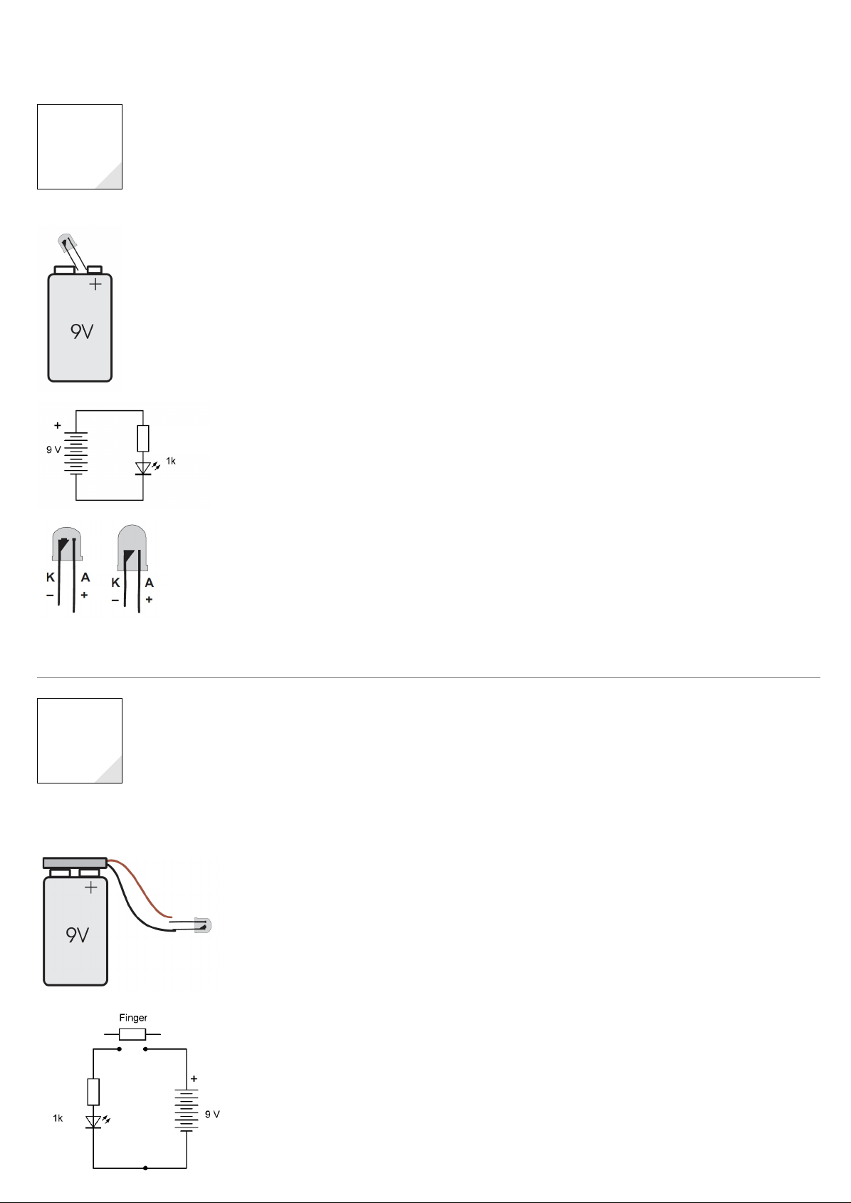
Opening the first door reveals a very special electronic component: a green LED with a built-in resistor. The LED case
of this diode is shorter than that of a standard LED without a resistor, to prevent confusion. Never directly connect
a standard LED to a battery or power supply. Standard LEDs always need a resistor connected in series to protect
them. No worries with this one – it comes with an built-in resistor in the form of a little cube visible on the (+) connector. What looks like a little goblet on top of the (-) pin is called the anvil.
The (+) pin of an LED is also referred to as the anode (A), the (-) pin is called the cathode (K). The lower rim of the
case has a flat spot on the side of the cathode. Also, the cathode pin is always the shorter one of the two. Means
there’s lots of help to distinguish between the two poles of an LED. Connecting an LED to a battery requires connecting the anode to battery (+) and the cathode to battery (-). An LED is basically a little electronic valve that conducts
electricity in only one direction, and lights only when conducting electricity.
Connect the LED to the battery poles and the green light flashes up. Caution: do not look into the emitted light at
close distance. And make sure you don’t short-circuit the battery poles by connecting them directly to each other.
This causes the battery to heat up which may result in an explosion if the battery is short-circuited for an extended
period of time. Moreover, short-circuiting reduces battery life significantly.
Electronic circuits are explained by circuit diagrams. Each electronic component has its own symbol. LED are represented by a triangle symbolising the anode and a line standing for the cathode. Two arrows symbolise light emission. The resistor is represented by a rectangular box. Each resistor has a characteristic value indicated next to the
box. In our case, the LED comes with an 1000 Ω resistor = 1 kiloohm =1kΩ = 1k. Despite our LED and resistor come
as a single physical entity, the diagram treats them as separate components.
The circuit diagram shown on the left constitutes a series circuit. Current passes from the battery through the LED
and the resistor back to the battery. The job of the resistor is to limit the current to a safe level. The higher the resistance, the less current can pass through.
Day 2
Again, never connect a standard LED directly to a battery without putting a resistor in place as well. Without the
resistor, the current passing through the LED is too high, damaging the component in the process. The only reason
we were able to do this here is because our LED features a built-in in resistor as indicated by the LED’s smaller case
size (see left).
2 Touch Current
Door No. 2 hides a battery clip for a 9 V PP3 battery. Change the setup of the Day 1 now using the clip. The black
lead connects to battery (+), the red lead to battery (-). Avoid short-circuiting the battery by bringing the black lead
into contact with the red one. Keeping the tow lead ends in contact with the LED poles might need a little bit of
practice. You can switch on and off the LED as you wish.
Now try this: bring the LED cathode into contact with the black battery lead whilst bridging the red lead and the LED
anode with a finger. The LED will still light up but with very low intensity (best to carry out this experiment in a
darkened room which will help you detect the glow much easier). Using the finger as a bridge allows a low current
to pass through that makes the LED glow.
+
–
The circuit diagram shows an circuit interruption that needs to be bridged using your finger. Basically, your finger
acts as a resistor with a resistance value that’s about 1000x higher than the built-in resistor of the LED. This means
that the light emitted by the LED is about 1000x weaker. The light intensity also depends on the moisture of your
skin, and on the pressure you apply to the contacts when touching them. If you moisten your finger a bit, the LED
light brightens. This experiments illustrates how a basic touch sensor works. We’ll revisit today’s topic again a couple
of days down the line, improving the design.
Green LED
Page 5
3 Steady Electrical Connections
5
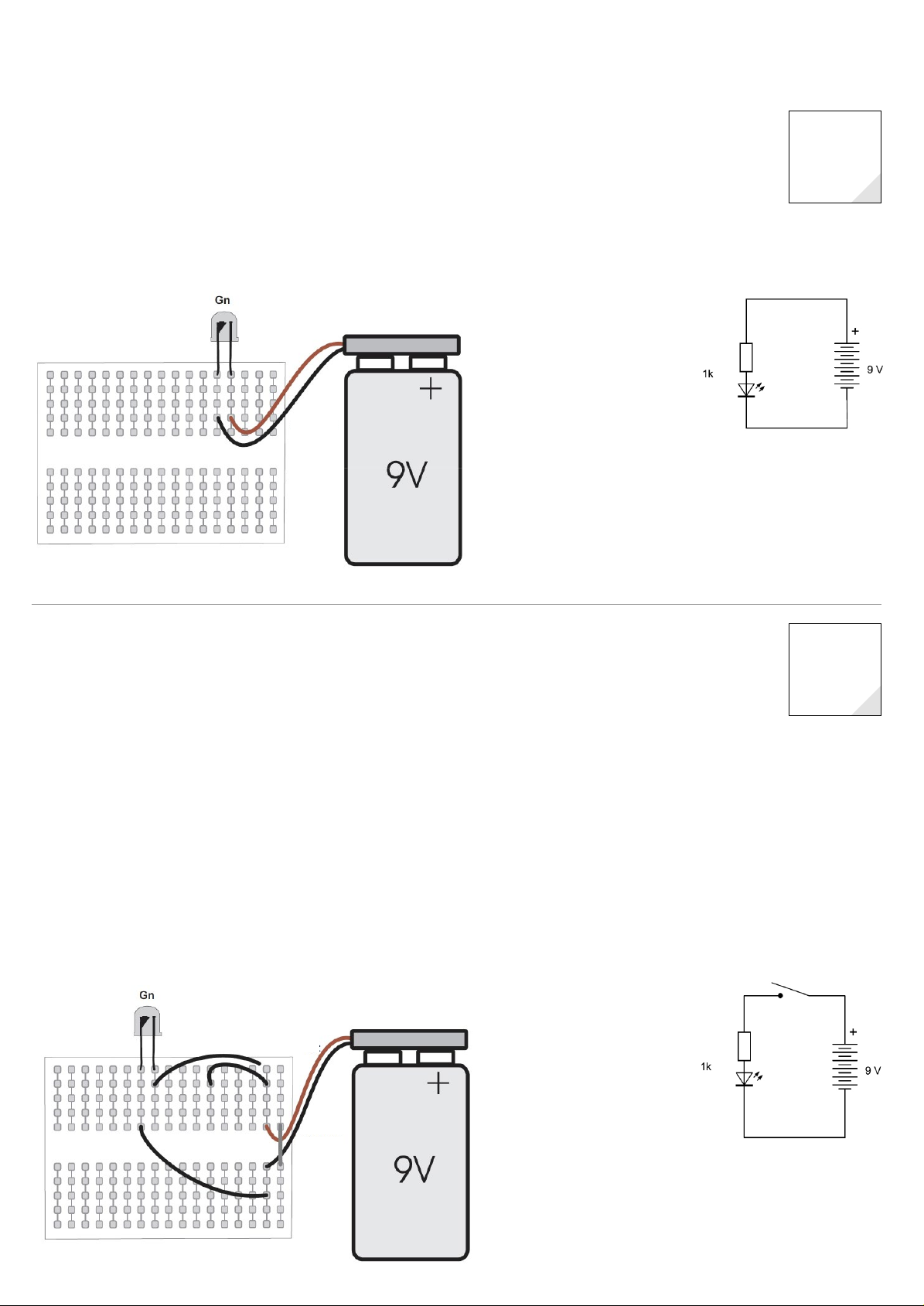
Opening the third door reveals a mini breadboard. Breadboards make circuit assembly easier. This one comes with
a total of 170 contacts, arranged in groups of five vertically interconnected slots. The board enables push-connecting
components which requires a certain amount of force and may result in the lead ends being bent in the process. To
prevent this, insert the wire ends in the slots approaching the board from a direction exactly perpendicular to the
board surface. Use tweezer or small pliers, grab the lead close to its end, and push it into the slot. This allows connecting sensitive leads such as tin-coated battery clips without damaging them. The LED lighting up means all your
connections are live.
Red
Black
Day 3
Green LED
4 Basic Switch
Today’s component is a copper wire with a red insulation. The wire can be used to built a basic switch, consisting
of two bits of stripped wire brought into contact by manual force i.e. applied by using your finger. Use a wire cutter
(or an old pair of scissors) to cut off bits of wire (about 2 cm long). Strip them. Bend the wires in a way that they are
close but don’t touch each other. Use your finger to bring them into contact, switching the LED on.
Moreover, and to protect the sensitive battery leads we use another bit of wire as a strain-relief for the clip. Also,
the clip should stay attached to the board to avoid tear and wear of the contacts. Cut off a bit of wire (approx. 2 cm
long) and strip the piece at both ends (about 7 mm at each end is fine). To strip the wire/ends, use a sharp knife,
score a circle around the cable jacket but try not to nick or slice the wire underneath as your connection might break
as a result.
Alternatively, bend the two wires forming your switch in a way that they make steady contact (aka normally closed).
Slide a small piece of paper between them and connect the paper to a thin string. Attach the string to a door or
window. If someone (e.g. a home intruder) forces the door or window open, the paper is pulled out from between
the wires, the circuit is closed, and the LED is switched on. In short, you’ve just assembled a basic burglar alarm.
Switch
Red
Day 4
Green LED
Black
Page 6
6
5 Resistor
Day 5
Green LED
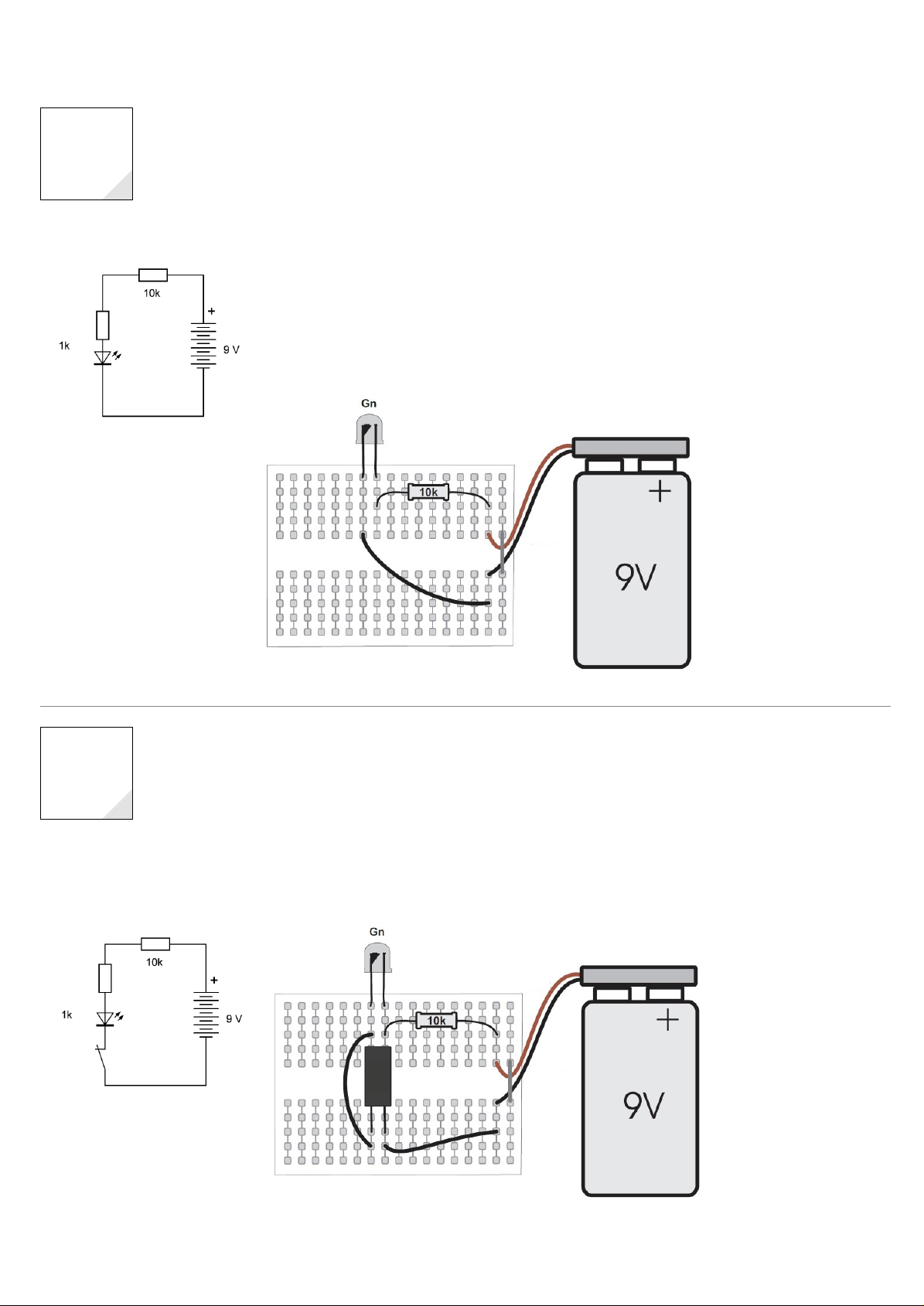
Day 5 means you get another resistor. The resistance values of resistors are indicated by a colour-code printed on the
resistor enclosure. The brown ring stands for (1), the black ring symbolises (0), and the orange-coloured ring encodes
(000), adding up to 10.000 Ohm = 10 kiloohm = 10kΩ. The golden ring represents component accuracy (95 %). The
high resistance value reduces the current passing through the LED. Lower current means less light intensity and,
thus, increased battery life. LEDs are very efficient devices and the emitted light is sufficient for a wide range of uses.
But see for yourself.
The circuit now has a total resistance of 11kΩ. Assuming the voltage across the LED is 2V results in 7 V across the
resistors, and a current of 0.65 mA. The capacity of a standard 9 V battery is 500 mAh, sufficient to supply a current
of 0.65 mA for a month. When carrying out the experiments make sure you save as much battery life as possible, to
ensure the battery has still enough juice to power your Christmas Eve experiment.
Red
Black
Day 6
Green LED
S
6 Tilt Sensor/Motion Detector
Opening door No. 6 reveals one of the key components of this calendar: a tilt sensor. It consists of an open contact
that will be close by a little metal bead as soon as the sensor is orientated in an upright position. When you tilt
the sensors, the metal bead slides off the contact and breaks the circuit. Vibrations cause the bead to jump up and
down, making and breaking electrical contact in an alternating manner. If you listen closely you can actually hear
the bead moving inside the sensor enclosure.
Add the tilt sensor to the circuit. Test whether the sensor works by slowly tilting the breadboard. Afterwards, shake
the board a bit, to make the LED flash.
Red
S
Black
Page 7

7 Vibration Sensor
7
Compartment No. 7 contains a red LED. Caution! Never directly connect a standard LED to a battery or power supply
without a series resistor since standard LEDs are designed for currents not exceeding 20 mA. Assemble a series circuit using the red LED the green LED with the built-in resistor and the 10kΩ resistor. The tilt sensor is supposed to
override the green LED, with current bypassing the green LED (thereby “short-circuiting” the LED). However, this is
an intentional short-circuit, with current limiting happening elsewhere in the circuit, resulting in the red LED being
switched on, and the green staying turned off.
Knock on the table top. The metal bead inside the tilt sensor jumps and breaks contact for an instant. You’ll see the
green LED flashing. Now use the assembled board to test various surfaces and orientations. Can you place the board
in a way that allows detecting an approaching person?
Rd
Red
S
Black
Red LED
Green LED
Day 7
S
8 Transistor as a Switch
Door No. 8 hides a component with three contact pins: a BC547C transistor. The pins of a transistor are referred to as
Base (B), Emitter (E) and Collector (C). The base pin is the one in the middle. The emitter is on the right (if you are
looking at the side that states the transistor type). Add the transistor to the circuit in a way that allows switching on
the green LED. The 10kΩ resistor provides the current flowing across the base. The wire loop L short-circuits base and
emitter, cuts off the base current, switching off the LED. Removing Loop L turns the LED on. Attach a thin string to the
wire loop and connect the other end to a door. Opening the door results in the loop being removed from the board
triggering the alarm.
Transistors are current amplifiers. Low current passing through the base results in a current multiplied in strength
passing through the collector. This means that transistors can be used as switches. A connection between collector
and emitter is established as soon as a current flows into the base. However, the polarity of the current needs to be
right. We are using an NPN transistor that requires the emitter being connected to battery (-).
Red
L
Black
Day 8
Green LED
L
Page 8

8
9 Alarm System
L
Day 9
S
Green LED
Opening the ninth door reveals another resistor. The colours grey-red-orange stand for a resistance value of 82kΩ.
Replace the current 10kΩ resistor with this one. The circuit now also features a main switch in the form of the tilt
sensor (S). And it’s only the operator who knows how to deactivate the alarm system – simply by tilting the board.
The system works exactly as before. The only difference is that the current passing through the loop (L) is now just
0.1 mA, i.e. much lower than in the previous layout. Means the battery capacity of 500 mAh is now sufficient to
power the circuit for more than half a year.
S
Red
L
Black
Day 10
Green LED
10 Touch Button
Compartment 10 provides you with another BC547C transistor. Using two transistors allows higher amplification
levels by boosting current levels already amplified by transistor one even further. This means that the tiny amount
of current passing through your finger is more than sufficient to power the LED. Strip two pieces of wire and add the
two the circuit. Touching the two wires (B) switches on the LED.
This type of electrical circuit is also known as Darlington pair (named after its inventor). Each of the BC547Cs comes
with a gain of 500, resulting in current passing through the pair being amplified by a factor of 250.000. This means
that you can use currents way below 1 μA to power the LED at full intensity.
Red
B
Black
Page 9

11 Light Sensor
9
Opening Door No. 11 provides you with a 1kΩ resistor (colour code brown-black-red). This time, we’ll employ the
red LED as a light sensor, not as a light emitter. Add the red LED to the circuit connecting the cathode to battery (+)
(back-biased orientation). Normally, this means that no current passes through the LED. However, if you place the
circuit board next to a bright light source, the LED will conduct a tiny bit of current. The two transistor amplify this
current to a level sufficient to power the green LED. Now shade the red LED with your hand. The green LED dims or
switches off. Test your light sensor in a variety of light conditions. Even in very low light conditions, you’ll notice a
little glow.
This circuit layout uses the red LED as a photodiode, with bright light triggering a very low current (adding up to a
couple of nA only) passing through the LED. The Darlington pair makes sure this current is boosted to levels high
enough to power the green LED. The 1kΩ resistor acts as a surge protector (in the case you accidentally connect the
red LED the wrong way round).
Rd
Red LED
Red
Black
Day 11
Green LED
12 Dimmer
Door 12 hides a new type of component: a 100 Nanofarad (100nF) ceramic disc capacitor (bearing the number 104).
Add the capacitor to the circuit with the Darlington pair. Also add two touch buttons using 2 stripped pieces of wire
each. Touching the upper sensor with your finger makes the LED brighter. Touching the lower button dims the LED
light. If you don’t touch any of the buttons, the LED maintains its brightness, at least for a while. This is due to the
capacitor having been charged to an average voltage level, feeding the two transistors that power the LED. After a
couple of minutes you’ll notice that the light intensity decreases.
Capacitors consist of two thin metal films separated by a layer of insulating material. Capacitors store electrical
charges, just like a battery, but at a much lower level. Electrical capacitance is measured in Farad, with 1 F representing a large capacitance. Most capacitors fall into the microfarad (μF), nanofarad (nF) and picofarad category. The
number 104 stands for 100.000, since 100 nF equal 100.000 pF.
Red
Black
brighter
Day 12
Green LED
darker
Page 10

10
13 Temperature Sensor
Day 13
Green LED
Compartment 13 contains a 1M resistor (1 Megaohm, colour-coded brown-black-green). Connect the capacitor with
battery (+). The capacitor charges up through the resistor and powers the Darlington pair. The LED lights up at maximum intensity for a couple of seconds dimming down afterwards maintaining constant light emission for a further
one or two minutes.
Zusätzlich ist der Kondensator ein wirksamer Temperatursensor. Bei einer leichten Berührung mit dem Finger
erwärmt er sich. Dabei wird die LED dunkler. Nehmen Sie den Finger weg, kühlt der Kondensator ab und die LED
wird wieder heller. Eine Änderung ist sogar erkennbar, wenn Sie Ihren Finger einige Millimeter entfernt neben den
Kondensator halten. Die Wärmestrahlung reicht dann für eine minimale Temperaturänderung.
Depending on the material, a range of ceramic capacitors show this kind of behaviour. Rising temperature reduces the
capacitance of the component. Despite being charged up as usual, the voltage passing through the capacitor is higher
which reduces the current flowing into the transistor base. This experiment illustrates how infrared temperature sensors
work. The only difference is that they use more sophisticated amplification processes. The capacitor also acts as a highohm resistor. This is down to an intrinsic capacitor property called dielectric remanence. If the LED has dimmed down
after a couple of minutes,
take the capacitor out and
add it again the other way
Red
Black
around. This resets the
circuit an you can start
again.
Day 14
14 Temperature Twin Sensor
Door 14 hides another 100nF capacitor (labelled 104). This enables adding a second temperatures sensor to the circuit.
Each sensor has a distinct function. Warming up the upper capacitor dims the two LEDs. Touching the lower capacitor brightens the LED light. Touch the sensors in an alternating way leads to fluctuating light intensities. The red LED
doesn’t just serve a decorative purpose: the component increases the voltage at the circuit input. Otherwise the lower
capacitor won’t be charged up properly and thus can’t act as a temperature sensor. As previously, after the initial full
brightness, the voltage passing through the circuit returns to an average level that will be maintained for one or two
minutes, during LED brightness may be controlled via the temperature sensors. If the LED light reaches very low levels,
briefly touch the upper capacitor to discharge it a bit to increase the current.
Green LED
Red
Black
Red LED
Page 11

15 Electric Field Sensing
11
Opening Door 15 reveals a 30 cm piece of wire that we’ll use as an antenna for detecting electrical fields. Once more,
we use a circuit layout centred around a Darlington pair. Bring your hand close to the antenna and then just move
your feet on a surface with insulating properties such as carpet or laminate flooring. The LED will flash in with your
feet movement. This happens without you making physical contact with the antenna, and is caused by a process
called electrostatic induction, during with electromagnetic forces attract or repel the electrons located in the antenna
wire. The reason for the LED glowing non-stop are AC fields emanating from power lines and mains cables around
us. Now fold the wire to shorten the antenna.
Electrical fields surrounding power cables and mains supplies seem to cause that constant glow of the LED. Fact
is that the LED isn’t continuously switched on but flashes 50 times per second instead (which you can see when
looking at the device out of the corner of your eye). Now place the breadboard close to a power cable. If the cable is
plugged into mains the LED lights up. You can even detect in-wall wiring.
Red
Black
Antenna
Day 15
Green LED
16 Electrostatic Motion Detector
Compartment 16 contains a third transistor that lets you boost the amplifier gain even further. Your electric field
sensor now attains a level of sensitivity that allows the detection of people passing the device in a distance of up to
six feet. However, make sure that you place the breadboard sufficiently far away from any cables.
The amount of static charge building up on people depends on the relative humidity, the flooring material they walk
on, and the type of shoes they wear. The dry air during the winter months in particular can result in people receiving
rather painful electric shocks. These charges may also reach levels high enough to cause damage to sensitive electronic components. This doesn’t apply to the transistors used in our experiments, so no need to worry.
Rd
Red
Black
Day 16
Green LED
Red LED
Page 12

12
17 LED Thermometer
Day 17
Green LED
Door 17 hides another temperature sensor, this time in the form of a resistor that has a resistance value of 4.7kΩ
at 25°C. Any rise in temperature reduces the resistance. This component is also referred to as a NTC resistor (NTC
stands for negative temperature coefficient) and can be used to measure constant temperature levels and detect
changes in temperature. Add the NTC resistor to a simple transistor circuit. The LED doesn’t light up at a temperature of 25°C. However, temperature dropping to 20°C increases the resistance to a level sufficient to power the
LED. Means you can use the device to determine whether the heating has been switched on in a room. Touching
the resistor with your finger turns off the LED. in theory, the role of the NTC resistor is no different from that of a
standard resistor powering the LED. However, this would require extreme temperature changes to be able to discriminate between different LED brightness levels. Using a transistor facilitates this by letting current passing through
only at voltages of 0.5V or above. The NTC resistor and the 82kΩ resistor form a voltage divider. At 25°C , a battery
voltage of 9V and a sensor resistance of 4.7kΩ result in voltages just below 0.5V, too low to activate the transistor.
At 20°C however, NTC resistance has reached 6kΩ feeding 0.6V to the transistor that is now able to power the LED.
The on/off transition is soft since the sensor accuracy is 80% which translates into an error of ±5°C. The temperature
threshold that the device
activates at also depends
Red
Black
on the battery charge. The
battery level dropping to
7V lowers the threshold
by 5°C.
Day 18
18 Temperature Switch
Opening Door 18 provides you with a 100kΩ resistor (colour code: brown-black-yellow) that enables us to add
another transistor to the circuit. This results in the function of the sensor being reversed, i.e. the LED now being
switched on at higher temperature level. Also, the soft transition between brightness levels is gone, the LED is either
on or off. Temperatures of 25°C or above mean the LED is on. If the temperature drops the LED is off. Touch the NTC
resistor with a finger to switch the LED on. Alternative, place the breadboard next to a radiator.
The simple on/off function is achieved by a feedback loop involving the 1MΩ resistor. Circuits like this are called
flip-flops as they alternate between two states. The little lag between switching on and off is referred to hysteresis.
Means the present circuit is similar to a clothes iron thermostat
Green LED
Red
Black
Page 13

19 Flashing Temperature Display
13
Compartment No. 19 contains another capacitor. This one is an 22 μF (microfarad) electrolytic capacitor that comes
with a capacitance 220 times higher than that of the ceramic disc capacitors. Caution! Electrolytic capacitors are
polarized i.e. they feature a (+) and (-) pin. The symbol representing this type of capacitor in the circuit diagram
consists of a black bar indicating (-) and a white bar that stands for (+).
Add the capacitor and a 10kΩ resistor to the circuit. This results in the green LED flashing as long as the temperature
keeps within a certain range. If the temperature drops below the minimum, the LED turns off. If the temperature
rises above the maximum the LED switches from flashing to constant light. Touch the sensor with your finger until
the LED starts flashing. Try to keep the sensor at a constant temperature level by lightly touching the disc capacitor.
Red
Black
Day 19
Green LED
20 25 Degrees Celsius Thermometer
Opening Door 20 reveals 47kΩ resistor (colour-code: yellow-violet-orange). The resistance is precisely 10 times
higher than the resistance of the NTC at 25°C, and acts as a reference. At 25°C both LEDs glow with the same brightness. If the temperature rises above 25°C, the LED turns brighter. Temperatures below 25°C cause the green LED to
brighten. Means this circuit can be used as a thermometer to keep room temperature at the recommended 20°C,
helping you save money on your heating bill.
The circuit comprises two voltage dividers and one differential amplifier. The common emitter current is divided up
depending on the voltage difference between the transistor inputs. At 25°C, the same voltage across the two voltage
dividers resulting in identical current powering each LED. Dropping temperatures increase sensor resistance and, in
turn, the voltage level at the base of the left transistor. This increases the brightness of the green LED, dimming the
red LED at the same time. Temperatures rising above 25°C dim the green LED, causing the red LED to become brighter.
The differential amplifier circuit constitutes a key component when it comes to precise voltage measurements, and
is also a vital part of op-amps. Our example demonstrates one of the advantages of this layout: the function of the
circuit does not depend on the circuit’s supply voltage. Means, dropping battery charge levels won’t affect the result.
Rd
Red
Green LED
Day 20
Red LED
Black
Page 14

14
21 Lie Detector
Day 21
Door No. 21 hides another 30 cm piece of wire to be used to assemble a lie detector. Strip two wires of equal length
half way down the line and wrap the stripped parts around the index and ring finger of the same hand. The wires
should neither be too loose nor too tight (i.e. cutting the blood flow). The circuit detects the level of skin moisture.
Relaxing for a bit will result in the LEDs glowing at a constant average brightness level. Telling a lie increases the
blood flow and thus the electrical conductivity of the skin which boosts the brightness of the LEDs.
This circuit represents a simple low-pass signal amplifier able to resolve slow voltage changes. A lack of capacitive
coupling using the 22μF capacitor leads to a weak current powering the LEDs. The actual current across the LEDs
is mainly determined by the 82kΩ resistor and the left-hand transistor. This circuit layout is also referred to as current mirror since the same amount of current passes through the collectors of the two transistors. Changes in input
voltage disturbs this current equilibrium, with the output current increasing or decreasing depending on the skin
resistance. The extra 100nF capacitor acts a low-pass filter to suppress high frequency interference.
Green LED
Red LED
Rd
Red
Black
Page 15

22 Electrosmog Detector
15
Compartment 22 contains another 1MΩ resistor (colour code: brown-black-green) constituting a part of a highly
sensitive amplifier comprising three transistors that also acts as a HF receiver. The circuit detects a wide range of AC
fields the strength of which is indicated by the brightness levels of the LEDs. Putting the antenna near power cables
allows you to pick up the 50Hz mains frequency . Also discover other types of EMFs emanating from a wide range of
electrical devices such as energy-saving light bulbs and cordless phones.
The 3-stage amplifier features a negative feedback loop that determines the amplifier’s bias point, generating an
averaged output voltage. However, and regarding the HF range, the 100nF capacitor suppresses the feedback loop
enabling maximum amplifier gain. The amplified AC voltage passes across the electrolytic capacitor to the LEDs
that also act as rectifiers.
Green LED
Red LED
Rd
22. Tag
Red
Black
Page 16

16
passing through the collector of the left-hand transistor very low, a low base current is sufficient to activate the timer.
23 Electric Spark/Static Discharge Detector
Day 23
Opening Door No. 23 reveals a yellow LED that connected in series to the green LED forms part of a timer. Activating
the circuit requires a light flash or an electrical impulse, means the layout contains an antenna (A) picking up EMFs,
and a photo sensor (i.e. the red LED). Electrical impulses can be generated by using an electronic cigarette lighter
within a distance of 10 cm (a standard flint lighter works, too, as it generates a bright spark). The LEDs switch off
after a couple of seconds. Further ways to activate the circuit are e.g. putting your hand next to the antenna and
shuffle your feet. The device will pick up the resulting electric discharges/EMFs .
The timer function relies on the current passing through the base of the right-hand transistor. The current stops as
soon as the 22μF capacitor has been fully charged. As a result the feedback loop switches off the LEDs. Basically, we
are talking an auto-deactivating flip-flop here (aka monostable multi-vibrator). As the 1MΩ resistor keeps the current
Green LEDRed LED
Yellow LED
YeRd
Red
Black
Page 17

24 Multifunctional Sensor
17
The last door hides a 100kΩ resistor (colour-code: brown-black-yellow). This year’s final circuit layout enables switching an LED on and off in a variety of ways. The circuit uses many of the sensors you’ve come across during your
previous experiments. Light might be switched on via a temperature sensor, a light sensor and an EMF detector. Turning the light off is achieved using a tilt/vibration sensor. Touch the NTC resistor. The LEDs light up within a couple of
seconds, depending on the temperature of your skin. To turn the light off, just knock on the table once.
If using the temperature sensor take too long to switch on the light, touch the stripped part of the antenna. This
generates an electrical impulse. Alternatively, use a lighter or actuate one of the light switches in the room. Both
generates an HF impulse that picked up by the antenna turns on the LEDs. However, the impulse generated by an
electronic cigarette lighter used at a distance of 10 cm works best.
Last but not least, there the light sensor in the form of the yellow LED. Pointing the beam of a bright torch at the LED
activates the circuit. Alternatively, use a camera flash. You can switch off the light at any time by knocking on the
table, or by tapping on the breadboard. Try to find more subtle ways to turn the LEDs on and off.
Yellow LED
Green LED
Red LED
Day 24
Ye
Rd
S
Red
Black
Page 18

18
Appendix: List of Components
1. Green LED with built-in 1kΩ resistor
2. Battery clip
3. Lead (30 cm)
4. Mini breadboard
5. 10kΩ resistor
6. Tilt sensor/motion detector
7. Red LED
8. BC547C NPN transistor
9. 82kΩ resistor
10. BC547C NPN transistor
11. 1kΩ resistor
12. 100nF ceramic disc capacitor
13. 1MΩ resistor
14. 100nF ceramic disc capacitor
15. Lead (30 cm)
16. BC547C NPN transistor
17. 4.7kΩ NTC sensor
18. 100kΩ resistor
19. 22 μF electrolytic capacitor
20. 47kΩ resistor
21. Lead (30 cm)
22. 1MΩ resistor
23. Yellow LED
24. 1kΩ resistor
Page 19

Liebe Kunden!
Dieses Produkt wurde in Übereinstimmung mit den geltenden europäischen Richtlinien hergestellt und trägt daher das CE-Zeichen. Der bestimmungsgemäße Gebrauch ist in der beiliegenden
Anleitung beschrieben.
Bei jeder anderen Nutzung oder Veränderung des Produktes sind allein Sie für die Einhaltung der geltenden Regeln verantwortlich. Bauen Sie die Schaltungen deshalb genau so auf, wie es in der
Anleitung beschrieben wird. Das Produkt darf nur zusammen mit dieser Anleitung weitergegeben werden.
Das Symbol der durchkreuzten Mülltonne bedeutet, dass dieses Produkt getrennt vom Hausmüll als Elektroschrott dem Recycling zugeführt werden muss. Wo Sie die nächstgelegene kostenlose
Annahmestelle finden, sagt Ihnen Ihre kommunale Verwaltung.
Warnung! Augenschutz und LEDs:
Blicken Sie nicht aus geringer Entfernung direkt in eine LED, denn ein direkter Blick kann Netzhautschäden verursachen! Dies gilt besonders für helle LEDs im klaren Gehäuse sowie in besonderem
Maße für Power-LEDs. Bei weißen, blauen, violetten und ultravioletten LEDs gibt die scheinbare Helligkeit einen falschen Eindruck von der tatsächlichen Gefahr für Ihre Augen. Besondere Vorsicht
ist bei der Verwendung von Sammellinsen geboten. Betreiben Sie die LEDs so wie in der Anleitung vorgesehen, nicht aber mit größeren Strömen.
© 2015 Franzis Verlag GmbH, Richard-Reitzner-Allee 2, 85540 Haar
Alle Rechte vorbehalten, auch die der fotomechanischen Wiedergabe und der Speicherung in elektronischen Medien. Das Erstellen und Verbreiten von Kopien auf Papier, auf Datenträgern oder im
Internet, insbesondere als PDF, ist nur mit ausdrücklicher Genehmigung des Verlags gestattet und wird widrigenfalls strafrechtlich verfolgt.
Die meisten Produktbezeichnungen von Hard- und Software sowie Firmennamen und Firmenlogos, die in diesem Werk genannt werden, sind in der Regel gleichzeitig auch eingetragene Warenzeichen und sollten als solche betrachtet werden. Der Verlag folgt bei den Produktbezeichnungen im Wesentlichen den Schreibweisen der Hersteller.
Bibliografische Information der Deutschen Bibliothek
Die Deutsche Bibliothek verzeichnet diese Publikation in der Deutschen Nationalbibliografie; detaillierte Daten sind im Internet über http://dnb.ddb.de abrufbar.
Alle in diesem Buch vorgestellten Schaltungen und Programme wurden mit der größtmöglichen Sorgfalt entwickelt, geprüft und getestet. Trotzdem können Fehler im Buch und in der Software nicht
vollständig ausgeschlossen werden. Verlag und Autor haften in Fällen des Vorsatzes oder der groben Fahrlässigkeit nach den gesetzlichen Bestimmungen. Im Übrigen haften Verlag und Autor nur
nach dem Produkthaftungsgesetz wegen der Verletzung des Lebens, des Körpers oder der Gesundheit oder wegen der schuldhaften Verletzung wesentlicher Vertragspflichten. Der Schadensersatzanspruch für die Verletzung wesentlicher Vertragspflichten ist auf den vertragstypischen, vorhersehbaren Schaden begrenzt, soweit nicht ein Fall der zwingenden Haftung nach dem Produkthaftungsgesetz gegeben ist.
 Loading...