

Page 1
BEFORE WE START
When you first connect the IoT-WiFi-board (hereinafter also:
NanoESP-) the computer may not find the required driver for the USB-to-Serial converter automatically. In this case, download the driver from
www.iot.fkainka.de/driver and install it manually. The Arduino- software will then
permit you to set the port and the board Arduino Nano (CPU: Atmega328). The
controller should then be ready to use.
You also need to make some settings for working with the serial monitor. The
Baud rate used is 19200 Baud. To send commands, you also need to select the
options CR and NL next to the menu for the Baud rate.
The proper settings in the Arduino environment
I worked with Arduino IDE versions 1.6.5 – 1.6.6. Older versions may cause problems. The current Arduino IDE version is available on the website
www.arduino.cc.
If you have any difficulties or problems with the board or the learning package, you
Page 2
can visit www.iot.fkainka.de for help. The page also contains a forum, new user
projects and all programs presented here in the latest version.
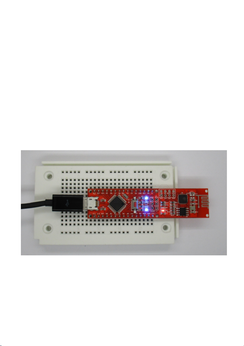
The learning package contains a pinboard on which you can pin the
NanoESP as illustrated below. This leaves you the most space for experiments,
while the WLAN module protrudes over the plug board at the rear. The Micro USB
cable can then be plugged in as shown in the picture in the following section and
will barely be in the way. More detailed setup images are enclosed with the individual chapters.
The IoT-WiFi-board (NanoESP)
The main element of this learning package is the IoT-WiFi-board (NanoESP). As
you can see quite well on the PCB, the board is made up of two components. The
left half is an Arduin-compatible micro controller system that can be compared to
the Arduino Nano. The right part is the WLAN module with the designation
ESP8266.
These two components communicate via a serial interface generated by software.
The NanoESP on the plug board
The pin layout of the board
The board has many different elements, such as the pins, some of which have
special functions, or the LEDs, the function of which is not always evident at first
glance. To prevent you from losing the overview, the following image lists the most
important functions of the individual elements.
Page 3

The most important pins and designations of the board
The WLAN module is controlled with AT commands. For this, the Arduino part of
the board is connected to the WLAN module via pins 11 and 12. A small circuit
converts the 5-V-levels into compatible 3.3-V-levels. Pins 11 and 12 should not be
used in your own projects for this reason.
Further important hardware properties of the board are summarised in the following table.
Technical Data
Microcontroller: ATmega328
Flash memory: 32 kB (including 0.5 kB for the boot loader)
SRAM: 2 kB
EEPROM: 1 kB
Cycle rate: 16 MHz
I/O-pins: 20 (including 2 for communication with the WLAN
module)
U
including PWM: 6
U
including analogue inputs: 6
USB-to-Serial chip: CH340G
Operating voltage: 5 V
Recommended input voltage: 7 – 12 V
Maximum current per I/O-pin: 40 mA
Resilience of the 3.3-V-output: 50 mA
WLAN-module: ESP8266
SPI-Flash 4 Mbit
Operating voltage: 3.3 V
WLAN standards: 802.11 b/g/n
WLAN modes: Wi-Fi Direct (P2P), Soft-AP
Firmware: AT-Firmware Version 0.22
Other Features: Integrated TCP/IP-stack
+19.5 dBm output power in the 802.11b-mode
Integrated Low-Power-32-bit-CPU
Communication via UART
Page 4

COMPONENTS IN THE
LEARNING PACKAGE
Find an overview of the parts contained in the learning package below.
1 IoT-WiFi-board (NanoESP)
1 pinboard
1 m circuit wire
2 button
1 9-V-clip
1 LED (red)
1 RGB-LED (4 connection legs)
1 resistor 10 kOhm (brown-black-orange)
1 resistor 1 kOhm (brown-black-red)
1 photo transistor (2 connection legs)
1 NTC 10 kOhm
1 Piezo speaker
1 potentiometer 10 kOhm with red dial switch
GETTING TO KNOW THE
MODULE
This first chapter is about the general functions of the WLAN-modules. The module is controlled with AT commands. All example programs shown here, help and
further information can be found at www.iot.fkainka.de
It is easiest to download the entire ZIP directory and copy the unpacked folder into
your sketch folder completely. Then you can open all programs comfortably in
sequence from the Arduino interface.
Page 5
1.1
|
Basic AT commands
For a first impression how to use the AT-commands, best just try them out. Therefore, this section will introduce you to some of the basic commands for the module.
For this, open the program P01_SoftwareSerial in the Arduino-IDE. This is a
very simple program that does nothing but pass on all data received via the serial
hardware interface of the micro controller to the ESP controller via a self-defined
software interface. The entire thing works in the opposite direction as well. As you
can see in the source text, the two connections of the software interface are pins
11 and 12. They should not be used as GPIO-pins in your own projects. You also
need the SoftwareSerial-Library that is pre-installed already in most Arduino
versions – if not, download the library via the manager.
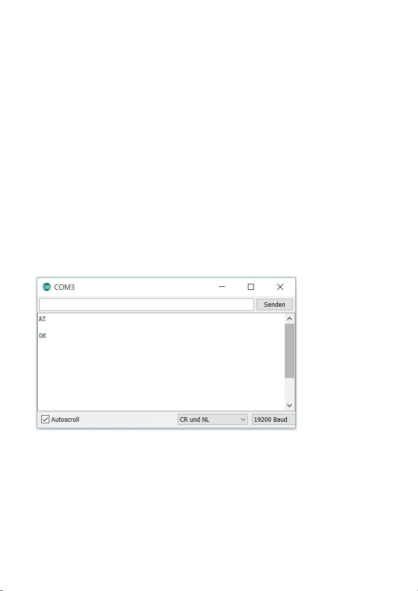
After the program has been uploaded, you can start the serial monitor of the Arduino interface. Before you can start, two important settings must be made to the
Serial Monitor, i.e. the baud rate must be set to 19200 in the lower right corner
and the setting CR and NL must be made in the box to its left.
Now you can see a message, i.e. AT and a few lines below OK. The command
AT was sent to the ESP module by the micro controller and the module answered
OK. You can see by this that the WLAN module works and is ready for use.
Terminal settings: CR and NL and a Baud rate of 19200
1.1.1 | Basic commands
You can now try out some basic commands of the module by simply entering the
command and sending it to the module with
[Enter]
. Capitalisation of the com-
mand is important. You can submit the first command of your own by entering
Page 6

AT
in the serial monitor and pressing
[Enter]
. The uploaded program passes on the
command to the ESP module, which in turn answers AT and then OK. The next
command that you can test is:
AT+GMR
This command outputs the current firmware and version number.
The command
AT+RST
resets the module. You will see a few illegible characters on the terminal first,
followed by ready, which says that the module is now ready. Another command is:
ATE0
This permits deactivating the echo of the module. This means that the command
you sent will not be returned, but only the answer will be. For example, if you send
AT, the response will not be AT and then OK, but only OK. However, for your first
attempts, it is recommended to reactivate the echo with
ATE1
.
Page 7
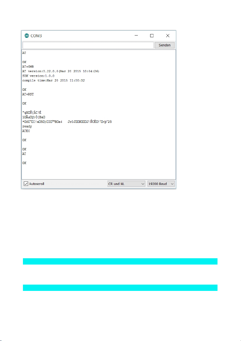
First attempts with the AT-commands
1.1.2 | WLAN-commands
The following WLAN-commands can be used to change the WLAN properties of
the module. Some commands not only permit specification of a condition, but also
requesting the current condition. This is done by entering a question mark after the
command, e.g.
AT+CWMODE?
The returned value usually will be
+CWMODE=2
followed by OK. If you enter
Page 8

AT+CWMODE=?
, the module will answer with the possible parameters for the command, in this
case 1-3. CWMODE is a command that you can use to specify the WLAN-mode,
by the way.
There are therefore three operating modes that I will explain below.
1
AT+CWMODE=2 – the module as Access Point (AP-mode)
In the delivery condition, the module is an Access Point. This means that you can
directly connect to the module with a WLAN-capable device, such as a smartphone
or a PC. For this, simply find the open WLAN with the name NanoESP and connect
to it. In the default condition, no password is assigned, so that connection is not a
problem. If you are connected to the module, you have no connection to the internet,
since the module is not a router with a dedicated connection to the phone network.
This WLAN-mode is still sensible, however, for example if you need a closed, safe
network. Speaking of safety: There is also the option of assigning a password to the
network, using the command:
AT+CWSAP
You need to enter parameters in the following order and separated with a comma:
U
the name of the network in quotation marks,
U
the password in quotation marks,
U
the channel ID (any value between 1 and 13),
U
and the encryption mode (value from 0-4).
One possible setting would be:
AT+CWSAP="MyNanoESP", "MyPassword", 5,3
After a short period, OK appears as confirmation. If an ERROR appears, check
your input again, and in particular check the quotation marks. If an ERROR appears anyway, check that the CWMODE is actually set to 2.
If everything works, you can connect to the board with a WLAN-capable device. All
devices connected to the module can be displayed with IP and MAC addresses
with the command
AT+CWLIF
.
Page 9

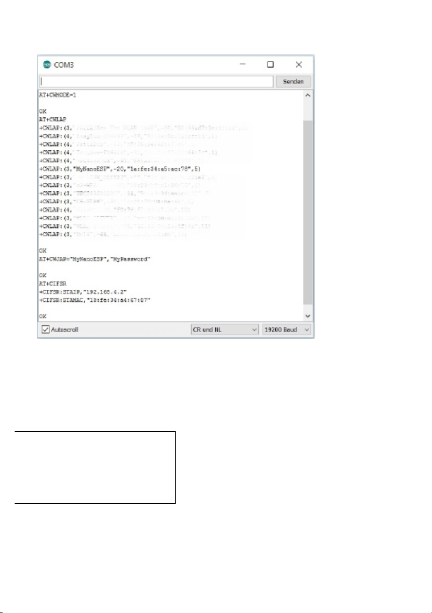
The module in station mode. The IP of the connected computer is highlighted.
2
AT+CWMODE=1 – the module in station mode
The command
AT+CWMODE=1
sets the module to station mode. This mode permits connecting to your WLANrouter. This will also connect the module to the Internet and give it a lot more options.
You can first use the command
AT+CWLAP
to list all networks in range to check if your network is within reception range. To
connect to your router, you need the command
Page 10

AT+CWJAP
Similar to the CWSAP-command, this has important parameters, i.e. the name of
the WLAN-network (also called the SSID) and the password, each again in quotation marks and separated by a comma. Connecting to a second module that is set
with the data according to the previous section would look as follows:
AT+CWJAP="MyNanoESP", "MyPassword"
It may take a few seconds to establish the connection. Then OK should be returned. You can call the IP of the module that the router assigns with the command
AT+CIFSR
. This will be important later when you want to connect to the TCP-server of the
module. The command
AT+CWQAP
will disconnect the connection with your router again.
Page 11
The board connects to a second NanoESP.
3
AT+CWMODE=3 – dual mode
The third possible mode for the WLAN setting is dual mode. As the name suggests, it permits operating the module in station and AP-mode. This means that
devices can establish a direct WLAN connection to the module, or reach the module through the router as an interim station. It is a practical mode, e.g. when you
are planning an internal network with several
modules, but want one module to serve as the
server that supplies all data to the network. We
will get back to this later.
1.2 | Automatic configuration
The basic commands can be tested manually already. This chapter is to explain
Page 12

how the commands can be automatically operated via the controller. You will also
learn another command that you can use to test if a computer in the network or a
server online can be reached. In this example, the Google server will be pinged.
The example program P02_GooglePing mostly automates the processes that you
entered manually in the first example. The controller sends commands to the ESP
module in sequence, thus connecting to the WLAN, among others. The differently
long time-out times give the module enough time to answer.
Before the program can work properly, you need to enter your WLAN data after #define SSID and #define PASSWORD right at the beginning of the program source code.
The module needs access to the Internet to execute its last command. The command
AT+PING
pings other devices in the network. Pinging means a query whether a computer
can generally be reached. Here, the Google server is pinged with
AT+PING="www.google.de". When a response returns, a success message appears on the serial monitor and the LED labelled D3 that is connected to pin D13
at the board is activated. The first communication with the Internet is successful.
The program
We will analyse the program functions step by step below. First, we will cover communication with the module.
1
Serial communication
This works via the serial software interface that is provided with the SoftwareSerial-Library. When initialising, you also need to indicate the pins used: in this
case these are pins 11 and 12.
001
#include <SoftwareSerial.h>
002
SoftwareSerial esp8266(11, 12);
Just as for the normal serial interface, you can then transfer bytes or entire lines
with the commands esp8266.print or esp8266.println. The commands
esp8266.find and esp8266.findUntil, with which an incoming stream can be
checked for specific character strings, are particularly useful as well. This makes it
rather simple to catch the matching response from the module. However, if an
expected character string does not appear, it may take a while until the program
continues. The waiting time (time-out) is defined byesp8266.setTimeout. findUntil()
can also be used to define a second character spring in which the search function
stops and returns false as the return value. We will use this in the function sendCom():
Page 13

001
//-------Controll ESP--------
002
003
boolean sendCom(String command, char respond[])
004
{
005
esp8266.println(command);
006
if (esp8266.findUntil(respond, "ERROR"))
007
{
008
return true;
009
}
010
else
011
{
012
debug("ESP SEND ERROR: " + command);
013
return false;
014
}
015
}
When you call the function, you therefore need to submit the command and the
expected return value to the function, e.g. AT and the expected return value OK.
println() transmits the command and finally waits until the expected return value or
an ERROR is received. When the expectation is met, the function returns the value true. Otherwise, the module will use the debug()-function to return an ESP
SEND ERROR and the sent command, so that it is easy to check which command
caused the problem.
Not all AT-commands have a unique or one-line return value. If, e.g., the IP address is queried, there usually is no previously known value. Therefore, a second
sendCom()-function exists that only needs the parameter command and will then
return the entire received string. The string should not be too long, since the buffer
of SoftwareSerial can overflow.
001
String sendCom(String command)
002
{
003
esp8266.println(command);
Page 14

004
return esp8266.readString();
005
}
2
Troubleshooting
There will often be errors and complication when developing programs. To have
any chance at all at finding them, there are two debug-functions that are activated
or deactivated via a parameter at the very beginning of the program.
#define DEBUG true
The first function does nothing but provide a simplified output of text via the serial
interface defined as standard. When the constant DEBUG is true, the content of
the string Msg will be sent.
001
void debug(String Msg)
002
{
003
if (DEBUG)
004
{
005
Serial.println(Msg);
006
}
007
}
The second function is also explained quickly. When the function
serialDebug is called, the program will switch to a permanent loop and will from
then onwards behave like the first tested SoftwareSerial-program. This means that
all data that are sent to the controller via the serial monitor will be passed on directly to the module and vice versa. In case of error, you can therefore call the
function and send manual commands to see where the error is located.
001
//---Debug Functions---
002
void serialDebug() {
003
while (true)
004
{
005
if (esp8266.available())
Page 15

006
Serial.write(esp8266.read());
007
if (Serial.available())
008
esp8266.write(Serial.read());
009
}
010
}
3
Configuration
To improve overview of the programs in general, most settings have also been
removed into individual functions, first of all the function espConfig, in which the
most important parameters for the respective program are set.
001
//---Config ESP8266---
002
boolean espConfig()
003
{
004
boolean success = true;
005
esp8266.setTimeout(5000);
006
success &= sendCom("AT+RST", "ready");
007
esp8266.setTimeout(1000);
008
009
if (configStation(SSID, PASSWORD)) {
010
success &= true;
011
debug("WLAN Connected");
012
debug("My IP is:");
013
debug(sendCom("AT+CIFSR"));
014
}
015
else
016
{
017
success &= false;
018
}
Page 16

019
020
success &= sendCom("AT+CIPMODE=0", "OK");
021
success &= sendCom("AT+CIPMUX=0", "OK");
022
023
return success;
024
}
At the beginning of the function, the variable success is set to true first, since this
variable is now and-linked to various functions. This means that even if only one of
the functions that have the value returns false, success will also immediately become false and the entire configuration will have failed. The first AT-command to
be reviewed for success this way is the Reset-command, which is nearly always
performed at the beginning of the program to ensure that prior tests are not still
using the module. However, it may take up to five seconds until the module returns
the message ready. Therefore, the time-out for esp8266.findUtil is increased just
before thesendCom()-function. After the reset, the time-out is returned to the standard value of one second.
This is followed by calling a self-defined function called configStation(), which will
be discussed in the next section. It is used to connect the module to your home
network. For this, the parameters SSID and PASSWORD will be transmitted that
you entered at the beginning of the program. If the connection has been successfully established, the success message and then the current IP of the module are
transferred to the serial monitor. At the end of the function, parameters will be set
that I will deal with later. Last, the variable success will be returned, which hopefully has kept the value true.
001
boolean configStation(String vSSID, String vPASSWORT)
002
{
003
boolean success = true;
004
success &= (sendCom("AT+CWMODE=1", "OK"));
005
esp8266.setTimeout(20000);
006
success &= (sendCom("AT+CWJAP=\"" + String(vSSID) + "\",\""
+ String(vPASSWORT) + "\"", "OK"));
007
esp8266.setTimeout(1000);
Page 17

008
return success;
009
}
The function configStation() has been called in the espConfig()-function. Here,
setting of the WLAN-mode to station mode with the command CWMODE and then
connection to the network via the CWJAP-command are performed. It can take
quite a long time until the connection is established. Therefore, the time-out is
briefly raised to 20 seconds here. If you prefer dual WLAN-mode, you can set
CWMODE to 3 here.
001
boolean configAP()
002
{
003
boolean success = true;
004
005
success &= (sendCom("AT+CWMODE=2", "OK"));
006
success &= (sendCom("AT+CWSAP=\"NanoESP\",\"\",5,0",
"OK"));
007
008
return success;
009
}
The function configAP() is not called here, but should be mentioned briefly anyway. It is the counterpart to the configStation()-function, since it is used to set the
module to Access Point. A long time-out is not necessary here, since the module
can process the CWSAP-command much faster. In later tests, the espConfig()function instead of the
configStation() will be used to call the configAP()-function.
001
void setup()
002
{
003
// Open serial communications and wait for port to open:
004
Serial.begin(19200);
Page 18

005
// set the data rate for the SoftwareSerial port
006
esp8266.begin(19200);
007
008
if (!espConfig()) serialDebug();
009
else debug("Config OK");
010
011
if (sendCom("AT+PING=\"www.google.de\"", "OK"))
012
{
013
Serial.println("Ping OK");
014
digitalWrite(13, HIGH);
015
}
016
else
017
{
018
Serial.println("Ping Error");
019
}
020
}
021
022
void loop() // run over and over
023
{
024
//Start serial Debug Mode - Type commands over serial Monitor
025
serialDebug();
026
}
The most important functions that you will find in nearly every program have now
been covered. These functions will now be used in the known Arduino functions
setup() and loop(). First, however, the two serial interfaces with 19200 Baud will be
initialised. Only then will the function espConfig() be called. In case of error, the
serialDebug()-function will be started at once. If everything went well, a success
message is sent. In later programs, the LED at Pin 13 that is marked with D3 on
Page 19
the board will also light up after successful configuration. This also gives you feedback when the module is not connected to a PC with serial monitor. In this experiment, however, the LED is needed for the feedback of the ping status. The query
takes place right in the next line of the configuration, too. The AT+PING-command
will be sent with the Google address as a parameter. You can query an IP address
from your local network instead of this address as well. In case of success, a message will appear and the LED D3 as mentioned will be activated. As the last action, the program will jump to the loop-function, which in turn will call the serialDebug()-function. You can therefore, test further commands after the program and
thus ping, e.g., further addresses.
1.3 | Recognition of a network
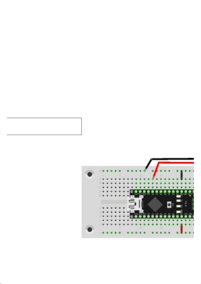
This chapter is, among others, about a smaller hardware setup for the first time.
The target of the project is a kind of alarm system that will react when a specific
network comes into range or is switched on.
Only two parts and some wire are used. The precise setup can be taken from the setup images.
Connection of the Piezo speaker
Page 20

The source text for this project differs from the previous experiment mostly in the
following functions:
001
void findSSID()
002
{
003
esp8266.println("AT+CWLAP");
004
if (esp8266.findUntil(ToFindSSID,"OK")) alarm();
005
else debug("SSID not found!");
006
}
007
008
void alarm()
009
{
010
debug("alarm!");
011
012
digitalWrite(LED_ALARM, HIGH);
013
014
for (int i; i <=30; i++)
015
{
016
tone(PIEZO, 400, 500);
017
delay(500);
018
tone(PIEZO, 800, 500);
019
delay(500);
020
}
021
022
digitalWrite(LED_ALARM, LOW);
023
}
The function findSSID() is called about every 30 seconds in the loop-routine and
Page 21

will then scan for all networks in the environment. When the network you are looking for has been found, the function alarm() will be tripped, which switches on the
LED D3 and emits a signal sound at the piezo. In the example program, we scan
for a network with the SSID NanoESP, i.e. actually other NanoESP-networks in
range. You can also enter another SSID in #define ToFindSSID at the beginning of
the program. Then you can check, for example, how far your WLAN-network goes.
UDP AND IP
This chapter covers general data exchange between two systems via a WLANnetwork. We will deal with subjects such as IP, ports and the UDP protocol. First,
let us explain these basic terms.
What is an IP-address?
An IP-address works like a postal address. It can be used to clearly identify and
address a computer in the network. An IP-address according to the still-common
IPv4-standard looks as follows:
192.168.4.1
These are four numbers, or rather four bytes. This means that the value of each
number cannot exceed 255. Generally, there are local IP-addresses, i.e. IPs that
are assigned, e.g., to the computers and devices in your home network, and global
IPs.
Local IPs are usually assigned by your router. They usually start 192.168. The
following number differs from router to router. If the NanoESP acts as Access
Point and computers can connect to its network, PCs will receive an address that
starts with 192.168.4. This opens a subnetwork at the same time. Fritz!Box routers
usually assign local IP-addresses according to the structure 192.168.178.X. You
can find out your IP by entering, e.g. the command ipconfig in the Windows com-
mand prompt (under Start -> Programs -> Accessories -> Prompt ). A longer list
will appear, which includes, among others, the item IPv4-address with your local
IP in the network.
Global IPs are usually assigned by your internet service provider. This is, e.g., the
address via which your router can be reached in the global network. The router
opens the local network and distributes the data to the clients. One way of finding
out your global IP is calling the website http://www.meine-aktuelle-ip.de/. That
website shows further data that can be viewed by a web server as well. You are
not as anonymous online as you may think.
Page 22

What is a port?
When comparing to a postal address, the port would be similar to the front door in
an apartment house. A computer with a unique IP can provide different services
via different ports. You can reach the server via the IP, but you use the port to
choose the service to be used. For example, this can be port 20 for FTP data
transmission or port 23 for a Telnet connection. You can usually select the port
freely; however, there are standardised ports that make handling web applications
easier. A list of standardised ports can be found at
https://de.wikipedia.org/wiki/Liste_der_standardisierten_Ports
What is UDP?
UDP is short for User Datagram Protocol. This is a minimal, connection-free network protocol. Generally, it is more minimalist and simpler than other internet protocols, such as TCP, which we will deal with later. The comparison is not particularly simple here yet, but you may remember the following regarding the protocol's
properties:
U
UDP is broadcast-capable.
U
It does not review the data for accuracy or correct errors.
U
There is therefore no guarantee that data have been successfully
transmitted.
U
There also is no guarantee that data have not been falsified on the
way or listened in on by third parties.
U
You do not need to establish a connection first. Quick data exchange
is possible.
U
There are barely any transmission delay fluctuations.
U
The format is suitable, e.g., for VoIP (Voice over IP – i.e. phone calls
via internet).
These are the most important basics on the terms for the following projects. The
subject can be dealt with in more detail still, and further information will follow in a
suitable location. First, let us deal with the practical part.
2.1 | Exchanging data between the board und PC by UDP
In this project on the subject of UDP, data are exchanged between the board and
the PC via the WLAN. The prerequisite for this is that your computer has a WLAN
adapter. A program on the PC-side ensures successful receipt of the messages.
You will not need any special hardware setup for this experiment.
The program
When you load the program P04_UDPBasics.ino onto the controller, the controller
Page 23
is configured as an access point and you can see an open network called
NanoESP NanoESP. Before connecting to the network, first download a program
from the Internet. In my experiments, I used the program Packet Sender by Dan
Nagle which you can download from the following link:
https://packetsender.com/
After loading and installing the program, you can connect your PC to the open
network of the NanoESP. Ensure that the firewall recognises the network as a
home network, to avoid blocking data. Your computer should now have the IP
192.168.4.2. You can check this by sending the command
AT+CWLIF
to the module via the serial monitor. This command shows all computers connected to the access point with IP and MAC addresses.
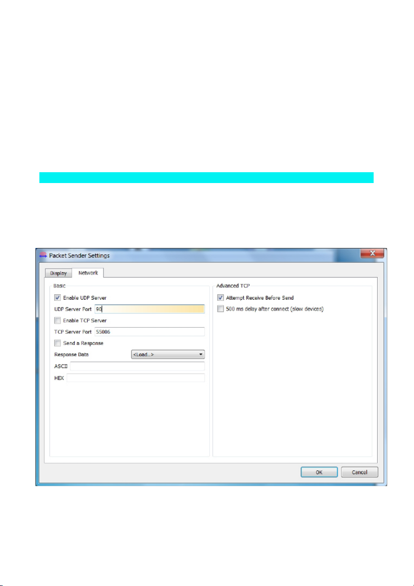
Start the program Packet Sender, set the UDP server port to 90 in Settings ->
Network and click the checkbox Enable UDP Server. In Usually, the lower left
should say UDP:90. If it does not, you need to restart the software once.
The proper settings in the program Packet Sender
The program on the computer is now used as UDP server, while the controller is
Page 24
set as UDP client. The differentiation between client and server is not clear in the
UDP protocol, but in this case it means that you will send data from your controller
to the computer.
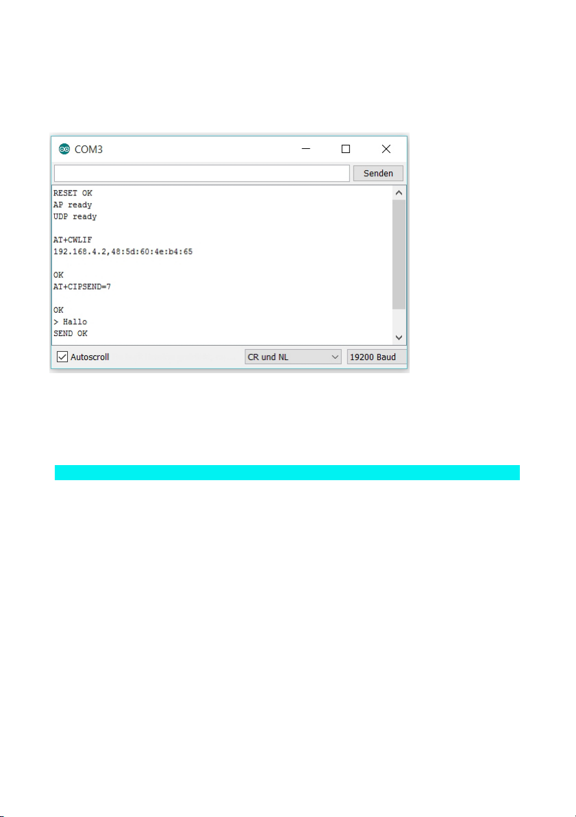
The message
has been successfully transmitted.
To send data, use the command:
AT+CIPSEND=7
The 7 means the number of characters to be sent. The character > is returned.
This means that you can now send your message. Enter Hello and confirm with
[Enter]
again. The module returns SEND OK, although you have only entered
five characters. This is because after your input, Carriage Return and New Line
are sent as well, i.e. two characters more that you need to include in your message length calculation.
When you switch back to the Packet Sender and look at Traffic Log there, you can
see the receipt of the message. In the ASCII view, you will even see the two enclosed characters, represented by \r and \n.
Page 25
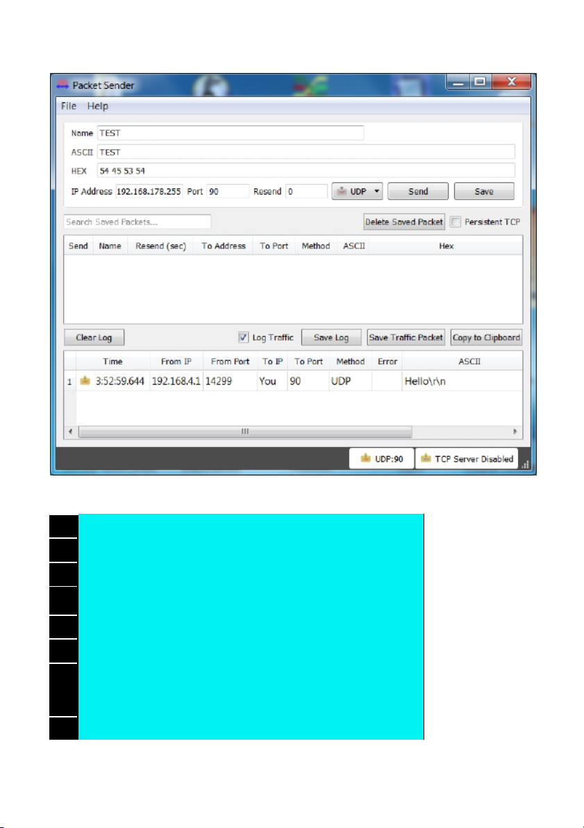
The message has been received by Packet Sender.
001
boolean configUDP()
002
{
003
boolean success = true;
004
005
success &= (sendCom("AT+CIPMODE=0", "OK"));
006
success &= (sendCom("AT+CIPMUX=0", "OK"));
007
success &=
sendCom("AT+CIPSTART=\"UDP\",\"192.168.4.2\",90", "OK");
//UDP-Server
008
return success;
Page 26

009
}
In the Arduino program, the function configUDP() is particularly decisive for the
communication path. The settings important for transmission are made there. First,
use CIPMODE to set the data transparency mode to 0. Finally, use CIPMUX=0 to
set that only one single connection is permitted. The decisive command is CIPSTART. It is used to establish a commutation, specifically to IP 192.168.4.2, i.e. to
your PC, and to PORT 90, where the program Packet Sender is listening with its
UDP-server. These are the steps that are initially necessary to establish the first
communication.
2.2 | Sending and receiving data with UDP
In the preceding project, the UDP communication was tested in one direction, i.e.
from the board to the PC. In this program, the module is set so that communication
in the other direction is possible as well, almost like in a chat.
The program
This program generally only contains a very small change that has a great effect
on the communication with the UDP protocol. When you upload the program, another access point with which you can connect to a PC is generated. Again, you
will need Packet Sender or a comparable program. Start the program and make
the same settings as before (File -> Settings -> Network: Enable UDP Server, Port
90). Then you need to enter the address of the module in the main window in the
IP Address field (192.168.4.1), set the Port to 91 and select the item UDP in the
dropdown menu farther to the right. When these settings have been made and the
serial monitor has been opened, you can send the first message to the module by
entering, e.g., Hi in the field labelled ASCII.
If you click Send now, the Serial Monitor will show:
001
+IPD,2:Hi
002
OK
Page 27
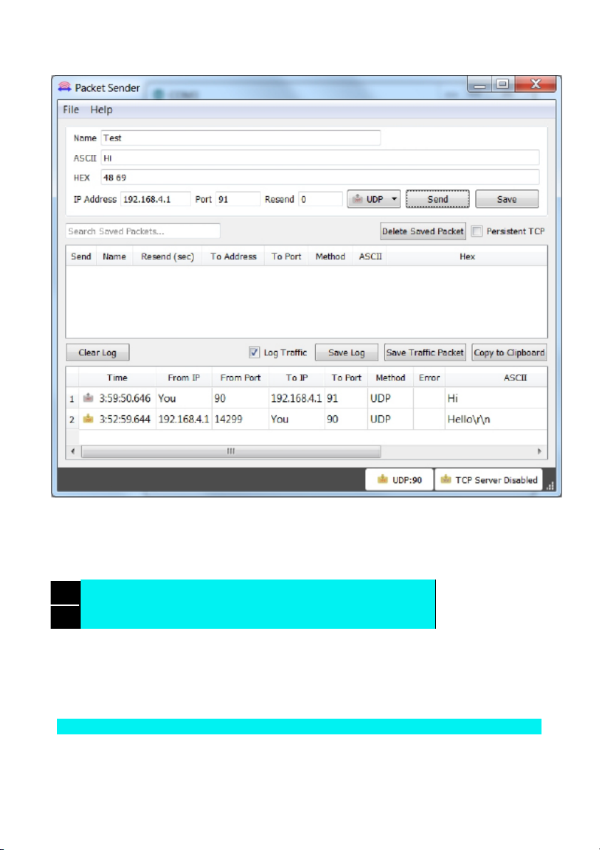
The Packet Sender has successfully submitted »Hi«.
The message has been received. You can answer by using the CIPSEND command again, i.e. for example:
001
AT+CIPSEND=7
002
>Hello
The difference from the previous program is only in a single line:
success &= sendCom("AT+CIPSTART=\"UDP\",\"192.168.4.2
\",90,91", "OK");
As you can see, a second port was indicated. This port, here the one with number
91, is the port through which the module listens for incoming data in turn. By attach-
Page 28

ing this simple line, you can also send data to the module. You can also listen at the
same port to which you are sending. You can therefore also enter 90 for both ports.
Theoretically, the change also permits the module to receive its own data.
2.3 | Switching an LED by UDP
The program P06_UDPLED.ino now finally is about controlling hardware with the
UDP. In this program, an LED can be switched on and off with simple commands.
Another setting is also made to the UDP communication, which permits the hardware to be controlled from several computers at once. For this, you need a circuit as
the figure below shows. The LED looks very similar to another part, the photo tran-
sistor. You can distinguish the two parts by looking
at the head of the part from above. The inside of
the LED has a large, white area.
The Packet Sender has successfully submitted »Hi«.
The program
While the prior example programs required many inputs by the user via the serial
monitor, this program is to work autonomously. Nevertheless, information will still
be output via the serial monitor for debugging purposes.
The controller will wait for data received from the WLAN module that are announced by the +IPD message. Legitimate commands that you can send via the
Packet Sender are led1 and led0. The controller interprets them and switches the
Page 29

LED on and off accordingly. Feedback to the transmitter is transmitted as well. If
another command is sent, the serial monitor reports "Wrong UDP Command". The
same message is also submitted to the transmitter via the network. In the source
code, we will first look at a line in the function configUDP() again:
success &= sendCom("AT+CIPSTART=\"UDP\",\"192.168.4,255
\",90,91", "OK");
The IP has changed now. This IP should look strange to you, since it is not the IP
of your computer. How can the data arrive at all? This IP works because it is a
special IP. This is called a broadcast-IP. The word broadcast is also used, e.g., for
radio channels. Just like radio channels, these broadcast data can be received by
all participants who are in the same subnet. Address 255 at the end of the IP always means a broadcast address. Now you can start the program Packet Sender,
e.g., on another computer, and listen to all sent messages and also send commands. Communication is no longer limited to two participants.
001
void loop() {
002
if (esp8266.available())
003
{
004
if (esp8266.find("+IPD,"))
005
{
006
if (esp8266.find("led")) {
007
int setLed = esp8266.parseInt();
008
digitalWrite(LED, setLed);
009
010
debug("LED=" + String(setLed));
011
if (sendCom("AT+CIPSEND=7", ">"))
012
{
013
sendCom("LED=" + String(setLed), "OK");
014
}
015
}
016
017
else {
Page 30

018
debug("Wrong UDP Command");
019
if (sendCom("AT+CIPSEND=19", ">"))
020
{
021
sendCom("Wrong UDP Command", "OK");
022
}
023
024
}
025
}
026
}
027
}
The inbound commands are analysed in the loop-routine, which is continually
gone through. Once data from the module arrived (esp8266.available()), they are
analysed for the presence of the characters »+IPD,«. If the command led is also
found, the command parseInt() automatically saves the next number in the variables setLed. According to our definition of the commands, this should either be 1
or 0 and therefore switch the LED high or low. Next, the debug-function and the
CIPSEND-command transmit a confirmation to the computer. If the command led
was not part of the data received by the module, an error message will inform of a
defective command. The first control via the network would now be complete.
2.4 | Network switch
The previous program assessed the first commands via the controller and
switched an LED accordingly.
The next program maintains this function but can also additionally send a com-
mand into the network independently. Connect a
button to the controller as shown in the setup
image.
Page 31

The switch, connected space-savingly to D8
The program
The program continues to evaluate the incoming commands. Additionally, however, the button is continually queried. When the user actuates it, the controller
sends the text
Button=1
to the network. All devices connected to the module with a UDP server on port 90
can receive the command. You can check this again with the Packet Sender. If
you have two controllers, you can set up the same circuit at the second controller
and upload the program on both controllers with a slight variation. If you replace
the command Button=1 with the command led=1, you can control the LED of the
respective other controller by pushing a button. However, you may also control the
LED of the own controller right along with it.
Page 32

The process in the Packet Sender
The changes to the program are mostly in the loop-routine. A simple if-query
checks if the switch is pushed. If this is the case, the controller will submit the
message Button=1 to the network. Additionally, there will be a debug-message.
The following while-loop prevents an entire flood of commands from being sent at
once while you push the switch. You need to release the button before the program continues.
001
if (!digitalRead(SWITCH))
002
{
003
debug("Button=1");
004
sendUDP("Button=1");
005
while (!digitalRead(SWITCH)) {}
006
}
Page 33

For a building automation project, a server would receive the status message, e.g.
of a motion sensor, and then send the command to activate the light to another
controller. This way, an entire network of sensors and actors can be set up.
2.5 | Analogue sensor
In the last project, a button was used to deal with the simplest form of a sensor.
This time, a potentiometer should be used as an analogue sensor to permanently
send measured values into the network. Use the
enclosed potentiometer with 10 kΩ for this. The
setup is shown in the lower figure.
The setup with potentiometer at A6
The program
In addition to the analogue sensor, there is also another change to the program.
This time, the controller is no longer to be operated in access point mode as before, but to connect to your home network. You can enter your station data simply
at the top of the program this time.
After the upload, it may be a while before the connection to the network is established. If this is successful, the LED D3, which is firmly equipped on the board,
lights up. This is the sign that the controller is ready. While the serial monitor is
active, you will see the corresponding message, but you may want to use the
board autonomously for later experiments. In this case, the feedback can be very
helpful. The serial monitor will also give you the information of which IP has had
the board assigned by the router. This IP is important, since you want to address
Page 34

the board later.
Communication with the board works similarly to the previous experiments. Only
the IP of the module and your computer will have changed, since both devices
now have had an IP assigned by the router. Packet Sender receives no measurements at first after the start. First, you need to send a message, e.g., the command led=1, to the module. For this, enter the new IP of the module in the Packet
Sender, which you can find via the serial monitor. After the command, new measurements will arrive approx. once per second.
The measured data are received by Packet Sender.
There is another change in the CIPSTART-command for this program. The broadcast address has been expanded because it cannot be said in advance which
subnet your router will open. The second change is the addition of a parameter, in
this case the second one. The new parameter permits changing the target address
of the
CIPSEND-command. The module listens in the entire space starting 192.168. first.
Once a command is received, the module will switch to the new IP.
success &= sendCom("AT+CIPSTART=\"UDP\",\"
Page 35

192.168.255.255\",90,91,2", "OK");
There are the following options for this parameter:
1
mode 0: This means that the IP and port will not change. This is also the default
setting, which becomes clear when you look at the other modes.
2
mode 1: The settings change once. This means: When the module starts with
the currently used broadcast address and then receives something from a PC, the
module will switch to the new address of the PC. In other words: the target IP that
you entered will be unnecessary then and the new address will be used to send to.
This address will be retained even if the module receives data from another PC.
3
mode 2: The settings change every time data are received from a new device.
This means that the IP will be able to switch to a new PC even if it has already
been changed once.
This is also the reason why you need to first send a command to the module before you can receive data. You should then be able to receive data from this computer as well. This is not the case if you send a message to the module again from
the new PC.
001
boolean sendUDP(String Msg)
002
{
003
boolean success = true;
004
005
success &= sendCom("AT+CIPSEND=" + String(Msg.length() + 2),
006
if (success)
007
{
008
success &= sendCom(Msg, "OK");
009
}
010
return success;
011
}
An analogue value is sent in the loop-routine. For this, the new function sendUDP() is used, which makes the known functions accessible more easily. There
does not always have to be a delay between sending the commands, since trans-
Page 36

mission takes some time. However, the frequency at which new data are transmitted is so high that the PC will be bombarded with messages.
TCP CLIENT
The last chapter was about the UDP, which can be used to send and receive data
easily. The protocol already permits implementing a large number of applications.
In this chapter, we will deal with the TCP (Transmission Control Protocol). The
module will take the role of the TCP client in this chapter. This is the role that your
PC at home has towards the web server. The difference between TCP and UDP
can be generally summarised as follows:
U
The connection is only between precisely two devices.
U
The packages sent are reviewed for transmission errors and
corrected if necessary.
U
TCP is used especially online.
U
The protocol is slightly slower than UDP, but also safer.
The protocol is used by your PC and a web server from which you want to load a
website to connect the two parties. The actual website content will then be transmitted in HTTP format (HyperText Transfer Protocol). How this works will be explained in the following chapter.
3.1 | A browser
This experiment uses the existing setup again. It is about getting to know the basic
structures of TCP communication with the serial monitor.
The program
The program's function is similar to the SoftwareSerialprogram of the first experiment, but among others, it connects to the WLAN inde-
pendently at start-up. This saves you a lot of typing and you can start more
quickly. Do not forgot that you need to enter your home network’s data into the
program. Then enter the following command line in the serial monitor:
AT+CIPSTART="TCP","www.example.com",80
Page 37

This command establishes a TCP connection to the website www.example.com.
Port 80 is the standard port for HTTP-queries. After confirmation of the connection
with OK you can enter the next command, which you already know:
AT+CIPSEND=40
You want to send a message through the connection you have just established,
after all. When you are asked to enter a text with >, first enter
GET / HTTP/1.1
and then push
[Enter]
.
[Enter]
will not appear on the serial monitor, but the
module will have received it. Then the message continues with
Host:www.example.com
followed by
[Enter]
twice. You need to send the inputs very quickly in sequence,
however. Best prepare a text document from which you can copy the lines quickly.
A long text is returned. The first part is the response of the server, containing
some information for the browser. The text after <!document html> is the website
that you can also see when you call the page www.example.com directly, but
purely text-based. A browser would interpret this text and present it in a form that
we understand.
Excerpt from the answer of the web server
This example shows the basics of the HTTP format. A client connects to a web
server. The DNS (Domain Name System) makes it possible to enter the domain
name in text form instead of the IP. It will forward the query to an IP that would be
Page 38

difficult to remember. When the client is connected, the browser will send a GetRequest query. This query at least needs to contain the requested page or resource (in this case the main page), the protocol used (http 1.1) and the requested
host (www.example.com). Entering the host is important, since several web addresses may be located on the same server and thus behind the same IP. If you
want to request another page than the home page, replace / e.g. with
/example.html. In addition to the requested sub-page, your browser will send a lot
more information than just the requested resource. Data such as the browser
used, operating system, screen resolution and other things will be submitted. This
permits the server to adjust content. Then the server will send a response that
looks equally complex at first. The header part of the answer contains a lot of additional information for your browser. The actual website content will come last.
3.2 | An Internet clock
This project uses the knowledge from the previous chapters to make the NanoESP
independently collect information from a website. The program specifically loads
the current time from a dedicated website and thus sets the internal clock of the
controller that is implemented by library to permit an accurate time indication. The
time will be output via the serial monitor. You only need the board for this setup.
The program
While the previous program still required mostly manual operation, this one program works mostly autonomously. The controller connects to the website entirely
independently:
http://chronic.herokuapp.com/
The URL can be used to call various time systems and time zones. The current
time valid in Germany in winter is queried by the URL
http://chronic.herokuapp.com/utc/in-one-hour
. Therefore, the call of the function
getTime() has the second parameter utc/in-one-hour. Based on the UTC (coordinated world time), you need to change the call to utc/in-two-hours in summer. You
can treat all other time zones according to the same system.
The determined time is now handed over to the Time-Library of Michael Margolis
(source: http://www.pjrc.com/teensy/td_libs_Time.html). For practical reasons, a
copy of the Time-Library version that I use is enclosed in the sketch folder. It must
be copied into the libraries folder of your sketchbook folder. In the background, the
new time is continually calculated and output in the terminal every second. You
can simply program an alarm clock or another time-controlled application. For
calling of the time to work, a new function must be used:
001
boolean getTime(String Host, String Subpage)
Page 39

002
{
003
boolean success = true;
004
int xyear, xmonth, xday, xhour, xminute, xsecond; //local
variables
005
006
success &= sendCom("AT+CIPSTART=\"TCP\",\"" + Host +
"\",80", "OK");
007
String getRequest = "GET " + Subpage + " HTTP/1.1\r\nHost:" +
Host + "\r\n";
008
success &= sendCom("AT+CIPSEND=" +
String(getRequest.length() + 2), ">");
009
010
esp8266.println(getRequest);
011
012
if (esp8266.find("+IPD"))
013
{
014
if (esp8266.find("\r\n\r\n"))
015
{
016
xyear = esp8266.parseInt();
017
xmonth = esp8266.parseInt();
018
xday = esp8266.parseInt();
019
xhour = esp8266.parseInt();
020
xminute = esp8266.parseInt();
021
xsecond = esp8266.parseInt();
022
023
if (xday < 0) xday *= -1; //Because of date separator parseInt detects negative integer
024
if (xmonth < 0) xmonth *= -1; //Because of date separator parseInt detects negative integer
Page 40

025
026
027
setTime(xhour, xminute, xsecond, xday, xmonth, xyear);
028
sendCom("AT+CIPCLOSE", "OK");
029
return true;
030
}
031
else return false;
032
}
033
else return false;
034
}
Parameters for the host address and the subaddress are submitted to this function. The Get-Request query is created from this and submitted to the TCP server
of the website after a connection is established. The server response now needs
to be analysed. For this, the entire request header part is skipped by scanning for
\r\n\r\n, which simply means continuing after a double Carriage Return and New
Line. The next numbers correspond to the date and time you are looking for, which
are saved in interim variables with a number of parseInt()-function calls. One special feature is the date, where individual values are separated by a dash. The parseInt()-function interprets this as a negative number. Therefore, the values are
simply multiplied by -1. Last, the time is set with the setTime()-function and output
once per second by the loop-routine. The clock is now fully functional.
3.3 | Temperature display
This project displays the current temperature and the general weather. Again, the
values are output via the serial monitor. Additionally, there is an intuitive output
with the RGB-LED. With a single look, you can
guess at whether it is sensible to take along a
warm jacket.
For this setup, it is important to connect the RGB-LED correctly. RGB means Red,
Green, Blue; the LED actually is made up of several LEDs with a shared cathode
connection. A combination of the different colours with different brightnesses per-
Page 41

mits presenting almost any colour. The LED should be connected to the PWM
outputs D3, D5, D6 of the controller with dropping resistors.
Connection of the RGB-LED to pins D3, D5 and D6
The program
The sketch again is about calling a website; this time, it is a page specifically programmed for this project that collects data from the weather page
http://www.openweathermap.com/
. On this page, you can get information on the weather in your town by varying the
URL. Just enter the city you want to query in the source text after City. As an example, I am using my home town Essen: www.temp.fkainka.de/?city=Essen
The program now reads the temperature from this page and shows the result in
colour via the RGB-LED. At the same time, the value is output via the serial monitor. The temperature range used in the example program for display on the LED is
–20 °C to +40 °C.
Generally, the program works almost exactly like the previous one, but with some
small special features. The function getTemp() this time collects the data and returns the current temperature, similar to the time function in the previous program.
001
void rgbTemp(int val)
002
{
Page 42

003
int green, blue, red ;
004
005
if (val <= 10 & val >= -20)
006
blue = map(val, -20, 10, 255, 0);
007
else blue = 0;
008
009
if (val >= 10 & val <= 40)
010
green = map(val, 10, 40, 255, 0);
011
else if (val >= -20 & val < 10) green = map(val, -20, 10, 0, 255);
012
else green = 0;
013
014
if (val > 10 & val <= 40) red = map(val, 10, 40, 0, 255);
015
else red = 0;
016
017
analogWrite(RED, red);
018
analogWrite(GREEN, green);
019
analogWrite(BLUE, blue);
020
}
Adjustment of the LED brightnesses is done in the function rgbTemp(). The mapcommand will convert the values into the matching byte values (0-255) and output
them at the LED. Blue means particularly cold temperature; it influences the range
of –20 °C to +10 °C. Green is involved in the entire temperature range, but is
strongest at value 10 °C. Red will only start at a value of +10 °C and has its maximum at +40 °C. This provides an intuitive colour code that suggests the current
temperature in addition to the more precise display on the serial monitor.
TCP SERVER
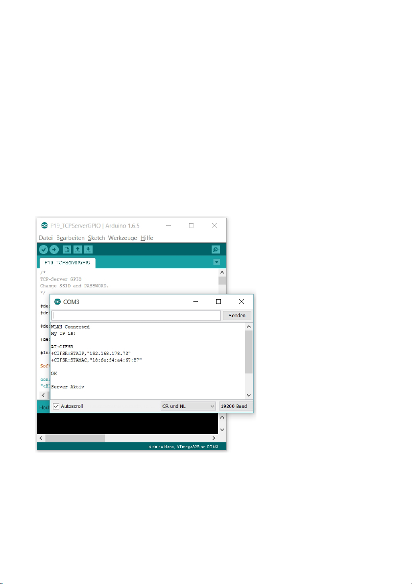
Page 43

After the last chapter explained a bit about use of the module as a TCP client, the
module is now to act as a dedicated TCP server. Practically, there is a simple AT
command for this with which you can start this complex server application. The
module will then act as a TCP server from the internet, except that you need to
program sending of the website yourself.
4.1 | TCP web server
The first attempts at a TCP web server are made without any additional hardware
setup. First, simply try out the most important commands via the serial monitor.
The program
Enter the WLAN data as before and load the program onto your board. Then start
the monitor. It may take a few seconds before the message that the board is connected appears. When the success message has appeared and the IP of the
module is displayed, you can start with the first command in the Serial Monitor:
AT+CIPMUX=1
This command permits multiple connections to the module. You can then access
the web server from several computers. Use the next command to start the web
server:
AT+CIPSERVER=1.80
The parameter 1 means that the server is being started. 0 terminates a server
again. The number 80 represents the port under which the server can be reached.
HTTP requests sent by the browser are generally sent through port 80.
You can now open a browser of your choice and enter the IP of your module into
the address bar and confirm it with
[Enter]
. The browser initially shows a loading
message, but the Serial Monitor will show a change. You can see a request query
similar to the one you have sent out manually before.
Page 44

The browserquery
The browser now waits for a response, and will show a loading sign until then, or
until the connection is interrupted due to time-out. You can send a message to the
browser with a version of a familiar command:
AT+CIPSEND=0.7
The parameter 0 indicates the client to which the message is to be sent here. This
is necessary because multiple connections are permitted and several clients may
therefore also be connected. The second parameter, here 7, again indicates the
characters to be sent. > appears, and you can enter a simple
Hello
and send it out with
[Enter]
. Nothing will change in your browser at first. You
need to close the connection before this can happen. For this, use the command:
AT+CIPCLOSE=0
Now you can see a Hello in your browser. You have now implemented a first web
server application.
This first experiment shows a lot about the precise processes of communication
online. The presentation of the »Hello« in the browser is still rather simple, since
simple text was sent instead of a complex HTML page. For a proper HTML page,
you need to manually write an entire header for the Get-Request and the HTML
text. I do not want to make you go to this effort for this first experiment, however.
4.2 | Autonomous web server
The results of the previous experiment are now to be used in an autonomous program. The new program not only sends a simple website to the browser, but also
Page 45

permits control of an LED. The setup picture also shows how to connect an exter-
nal power supply to the board. As an alternative to
this kind of power supply, you can also use a
power bank (an external rechargeable battery,
usually for Smartphones), which can supply the
board easily via the micro-USB connection.
How to connect the battery to the test setup.
The program
The program sends a slightly more complex page than the previous experiment.
You can also switch the LED at pin D9 by entering /LED after the IP of the module.
The current condition of the LED is then inverted, i.e. the condition will toggle each
time.
Enter the WLAN data and upload the program. The board's IP is displayed in serial mode. Then you can open the browser and call the board's IP. The website now
has a headline and a little more text. The text indicates how to control the LED.
This gives you the first fully automated web server.
001
void loop() {
002
if (esp8266.available()) // check if the esp is sending a message
003
{
Page 46

004
if (esp8266.find("+IPD,"))
005
{
006
debug("Incoming Request");
007
int connectionId = esp8266.parseInt();
008
009
if (esp8266.findUntil("LED","\n")) digitalWrite(LED, !digitalRead(LED));
010
011
String webpage = "<h1>Hello World!</h1>Open [IP]/LED to Toggle LED on D9";
012
013
if (sendCom("AT+CIPSEND=" + String(connectionId) + "," + String(webpage.length()),
">"))
014
{
015
sendCom(webpage,"SEND OK");
016
sendCom("AT+CIPCLOSE=" + String(connectionId),"OK");
017
debug("Send and Close");
018
}
019
}
020
}
021
}
To start the web server, you can use a simple function again. It is called configTCPServer(). This is simply what you entered manually before. The loop-routine
waits for inbound data. When these data contain »LED«, the LED is toggled. The
routine does not care about where »LED« is placed. Therefore, the command in
the submitted URL is legitimate. In this experiment, the website is in the webpagevariable and contains the following text:
001
<h1>Hello World!</h1>
002
Open [IP]/LED to Toggle LED on D9
<h1> is an instruction to the browser to display the text until </h1> as a headline
Page 47

of type 1. This is not proper HTML code yet, but only a simple form of text formatting. The length of the website is handed over with webpage.length() (a stringclass function) to the CIPSEND-command and the page is finally transmitted.
4.3 | Website with buttons
In this experiment, the illustration of the website is even more sophisticated. There
are now also control elements that permit much more comfortable control of the
LED. The experiment setup does not differ from that of the previous one: an LED
at Pin D9 that can be controlled via the module. The source text contains a few
changes, though.
The program
After uploading the program, you can call the controller website in a browser
again. You just need to enter the IP of your module that is output via the serial
monitor when starting. The website is, however, saved a bit differently in this project than it was in the last one.
The website of a web server
While the simple website was contained in the source text before, the page is
saved in a Progmem variable (Program Memory) this time. Using this storage type
relieves the SRAM of the board, which would otherwise be in charge of storing
variables. The SRAM holds only 2 kB and is very stressed already by use of the
strings. The Progmem function now holds the website content in the program
memory, which is much larger at about 32 kB. Access to the data is also somewhat more complex due to this, however.
001
const char site[] PROGMEM = {
Page 48

002
"<HTML><HEAD>\n<meta name=\"viewport\" content=\"width=device-width, initialscale=2.0,
003
(…)
004
};
This excerpt shows how the website is saved in the Progmem variable. This is a
longer HTML document in a C-compatible format. The format is, among others,
characterised in that quotation marks are displayed in the form \" and new lines by
\n. You probably know this from other projects that have strings. You can also find
a preview of the website in HTML format in the program folder.
001
String createWebsite()
002
{
003
String xBuffer;
004
005
for (int i = 0; i <= sizeof(site); i++)
006
{
007
char myChar = pgm_read_byte_near(site + i);
008
xBuffer += myChar;
009
}
010
011
return xBuffer;
012
}
In the function createWebsite(), the content of the Progmem variable will be loaded and returned as a string. It is clear how the Progmem variable is loaded from
the program memory again.
001
boolean sendWebsite(int connectionId, String webpage)
002
{
003
boolean success = true;
004
Page 49

005
if (sendCom("AT+CIPSEND=" + String(connectionId) + "," +
String(webpage.length()), ">"))
006
{
007
esp8266.print(webpage);
008
esp8266.find("SEND OK");
009
success &= sendCom("AT+CIPCLOSE=" + String(connectionId),
"OK");
010
}
011
else
012
{
013
success = false;
014
}
015
return success;
016
}
The loop-routine now waits for a request query. When this arrives, the function
sendWebsite() will be called, with the result of the createWebsite()-function handed over to it as a parameter. This way, the length of the text can be determined
with the length()function. After transfer of the website, the connection is finally closed again with
the AT+CIPCLOSE-command. Switching of the LED is also part of the looproutine and will differ slightly from the preceding chart. How this is done precisely
is made clear in the following HTML crash course.
4.4 | Insert: HTML crash course
This chapter will contain a brief HTML crash course. I want to specifically focus on
the creation of websites for controlling the NanoESP. The course will cover the
basic structures of an HTML document, creation of in- and output elements and
finally integration of own websites into the Arduino program.
An HTML file is always characterised by <HTML> at the beginning of the document. The document end should be marked with </HTML>. Usually, the start and
end of a section or element are displayed comparably, as you can also see in the
header. The header contains important information and shapes, e.g. the title of the
website to be displayed in the browser bar in this case. In this case, the header
contains another piece of information that does not belong to the basics of HTML
Page 50

but improves presentation on mobile devices (<meta name ="viewport" …). You
can use these lines in your HTML website at all times.
001
<HTML><HEAD>
002
<meta name="viewport" content="width=device-width, initial-scale=2.0, userscalable=yes">
003
<title>
004
Switch LED
005
</title>
006
</HEAD>
After the HEAD, you need the BODY. It contains the content of the website. In the
starting area of the BODY, additional parameters such as the background and font
colours are specified. You can, of course, adjust them to your own wishes at any
time. Afterwards, the font face and size are specified in the FONT-element. They
only apply to the text Switch LED, here, which is made particularly large by this.
Afterwards, the FONT-element is closed again with </FONT>.
001
<BODY bgcolor="#FFFF99" text="#000000">
002
<FONT size="6" FACE="Verdana">
003
Switch LED
004
</FONT>
The next part is rather similar, but using two new elements, i.e. <HR>, which creates a horizontal line on the website, and <BR>, to jump to the next line.
001
<HR>
002
<BR>
003
<FONT size="3" FACE="Verdana">
004
Switch the LED <BR>
005
on D9 ON and OFF
006
<BR>
007
<BR>
Page 51

All elements presented so far were pure form factors that are used to design the
website. Next will be the important form-element to switch an LED.
001
<form method="GET">
002
<button type="submit" name="led" value="1">LED ON</button>
003
<button type="submit" name="led" value="0">LED OFF</button>
004
</form>
The form-element is, as the name suggests, meant to create forms online. These may
be registration forms for a website or surveys or similar things. The data entered by the
user can be transferred in different ways. For this element, we use the GET method,
where the entered data are simply transferred to the web server using the URL. This
form uses two buttons for this. Both are the type submit, which means that the form will
be transmitted directly when one of the buttons is pushed. Both buttons are named
led, but they have different values. When pushing the first button with the text LED ON,
the current URL will be called again, but with a small addition. Behind the URL, in this
case behind the IP of the module, you will now read /?led=1. This text is assessed in
the Arduino program by scanning for it and then reading the following digit with parseInt() and transferring it to the LED. With this first simple version of a form, you can
easily and comfortably control an LED.
This is what the URL looks like after the button LED ON has been pushed.
001
<BR>
002
<HR>
003
004
</font>
005
</HTML>
The last lines of the HTML source code do not contain anything new. Jumping to
the next line and a horizontal line complete the appearance before the document
is ended with </HTML>. You can now change the website in the sketch folder as
Page 52

you like. You can, for example, change the background colour or add more text to
the website. However, do not overload the website. The SRAM will reach the end
of its capacity quickly. When you have completed the changes, it is time to transfer
it to your Arduino program. For this, copy the entire text into the clipboard and go
to the website with the Swiss Converter Tool:
http://www.percederberg.net/tools/text_converter.html
The Swiss-Converter-Tool page after successful conversion
Enter the text from the clipboard, and in item 2. Select Output: set C/C++/PHP –
StringText and UTF-8 – Unix (LF). The lower window will show the Arduinocompatible text now that you can copy into the Progmem variable site. When
uploading the changed program with the new variable, you can see the new website when calling the board-IP in your browser.
4.5 | Controlling the RGB-LED via TCP
This project is about controlling the RGB-LED with a website on a web server. A
well-structured interface can be used to change the colour of the LED. The web-
Page 53

site has been adjusted and should be easy to
display even on Smartphones. The required setup
is shown in the lower figure.
Connection of the RGB-LED to pins D3, D5 and D6
The program
The new transmitted website is again placed in the Progmem variable site. Again,
you can view the HTML page in the Sketch folder. After setting the WLAN data and
uploading the program, the website of the web server can be reached via the IP of
the module. The page is designed similarly to the previous one in background colour
and headline. However, there is a new element on the page, i.e. the HTML5-element
Color Picker. It can be used to select a colour for the LED. Once you have confirmed
the colour, the LED will display it. The display of the Colour-Picker element may
differ strongly depending on the chosen browser.
Page 54

The website in your browser
Selection
of the colour in the
Chrome browser
Even if the design of this website does not differ greatly from the previous one,
there are some elements that I would like to describe in more detail. First, there is
a change in the header of the HTML document, referring to the following line:
<link rel="icon" href="data:;base64,iVBORw0KGgo=">
Page 55

This line is meant to stop the browser from trying to load the Favicon after loading
the website. Usually, a website has another special icon that differs it from other
websites and clearly identifies the website in a browser bar with several tabs. For
the browser to load this character, it will send a second request query after calling
the page and ask for this Favicon. You may have noticed this additional Request
query in your first experiments with the TCP server. To prevent the second query
and keeps unnecessary stress from the board, the above code line informs the
browser not to send a second Request. I recommend using this line for your own
HTML pages.
The second special feature in this document is the Color-Picker element that I
mentioned. It replaces the buttons in the previous example. This is a relatively new
HTML5 element.
In the previous website, we simply used buttons of the type submit so that the form
values were transmitted directly when pushing them. This is, unfortunately, not
possible when using an input element of the type color. One way of solving this
problem would be creating a button of type submit that would have to be pushed
separately after setting the colour. We will demonstrate this in a later experiment.
Here, we have entered a small JavaScript code (this is the part onchange="this.form.submit()"), which transfers the form immediately after a change.
The Color-Picker element in the Android-5.0browser
This way, we do not need an extra button.
001
<form method="GET">
002
<input type="color" name="rgb" onchange="this.form.submit()"><BR>
003
</form>
Page 56

The chosen colour is now transmitted in the form /?rgb=%23, followed by six more
characters. The expression %23 suggests that this is a hexadecimal digit. For the
colour white, the URL therefore is:
[IP]/?rgb=%23ffffff
The controller now needs to extract the individual colour values of the LED from
this HEX number, which is done in the following part of the loop-function:
001
if (esp8266.findUntil("?rgb=", "\n"))
002
{
003
String hexstring = esp8266.readStringUntil(‚ ‚);
004
long number = (long) strtol( &hexstring[3], NULL, 16);
005
006
int r = number >> 16;
007
int g = number >> 8 & 0xFF;
008
int b = number & 0xFF;
009
010
analogWrite(RED, r);
011
analogWrite(GREEN, g);
012
analogWrite(BLUE, b);
013
}
The function strtol() initially converts the text received behind %23 into a longfigure and this then into three byte values by bit manipulation. These are then
transmitted to the RGB LED with the analogWrite()-function.
4.6 | Light sensor
In this project, the website of the web server is not used as control interface, but
as output element. The brightness measured via a brightness sensor is displayed
well-structured as a relative value with a new HTML element.
Setting up this experiment requires the photo transistor, which is used as a light
Page 57

sensor. The photo transistor can easily be mistaken for an LED. You can recognise the photo transistor by looking onto the head of the part from above. The
photo transistor has a large black area inside. The following figure shows how the
experiment is set up. The collector of the photo transistor is the shorter connec-
tion. It is connected to +5 V. The resistor in series
with the photo transistor has 10 kOhm.
Connection of the photo transistor to pin A6 with 10 kOhm counter-resistor
The program
Until now, the websites of the web server were always made up of an unchangeable page that sent data to the controller. Now, the website is to be changed before being transmitted to the browser, to display the appropriate brightness of the
photo transistor. This works because the source code of the website holds a kind
of placeholder. The program now replaces the placeholder *bright* when loading
the data from the Progmem variable by the current brightness value. Thus, the
output text and the deflection of the slider are changed. Another line in the HTML
file ensures that the page will reload automatically every few seconds. The current
brightness is already displayed well-structured in the browser.
Page 58

The website of the brightness sensor
For the system to work, the HTML files have a few small changes again. The first
change is about in the header area:
<meta http-equiv="refresh" content="3">
This small line ensures that the browser automatically re-loads the website every
three seconds. This way, you do not have to push
[F5]
, all the time to view new
values.
The second change is placed where the form-element would usually be found:
001
<label for="hell">Current Brightness: *bright*</label> <BR>
002
<input type="range" max = "1024" name="hell" value=*bright*><BR>
You do not need any form here, since you will only use the website for output. The
two elements label and range are used as output elements. The label, which is
usually used for labelling, contains the item *bright* in the text. The slider element
range has the value *bright* assigned, which is not really a legitimate value, but
will be replaced by one later. The maximum value of range is 1024 and thus has
been adjusted to the 10 bit range of the controller's ADC.
Now, you only need to ensure in the source text before transmitting the website
that the placeholder *bright* is replaced by a legitimate value.
001
String createWebsite()
002
{
Page 59

003
String xBuffer;
004
005
for (int i = 0; i <= sizeof(site); i++)
006
{
007
char myChar = pgm_read_byte_near(site + i);
008
xBuffer += myChar;
009
}
010
011
xBuffer.replace("*bright*", String(analogRead(SENSOR)));
012
013
return xBuffer;
014
}
The placeholder is replaced in the function createWebsite(). First, the Progmem
variable is loaded from the memory as usual and saved in a string. Before the
function returns this string, however, all *bright*-strings are replaced by the value
currently measured at the sensor. The string function replace() will do the work
fully automatically. Finally, the changed string can be returned and transferred to
your browser by the known mechanisms.
4.7 | GPIO-Control
This new project permits simple control of the digital pins D2-D7 via the website.
The status of the respective pin is also presented in the browser, so that you will
never lose the overview.
To review the condition of the pin well, a setup as in the figure below is recommended. Both the RGB-LED and the regular LED are used. The cathodes of the
LEDs are now not connected to the long ground line on the outside of the board,
but are also at a digital output. Only when these
pins are switched low can the LEDs light up.
Page 60

Connection of the LEDs to D2-D7
Attention! LEDs must not be connected without dropping resistors. In this case it is
permitted due to the On resistors of the internal port FETs of approx. 30 Ohm.
Because the LEDs are placed between two ports, they actually work with a dropping resistor of 60 Ohm. Depending on LED type and colour, an LED current between 15 mA and 30 mA at most occurs. This is still permitted.
The program
The website of this program uses check boxes as HTML elements. When you
upload the program and call the page of the board, you can see a number of boxes that can be clicked. A check mark in a box means that the pin is high. No check
mark means low. You can now try out which pins need to be high and which ones
need to be low for all LEDs to be lit.
Page 61

The website GPIO control
This HTML code uses the website as input form and output element alike. If you
look at the form element, you can see that a number of input elements of type
checkbox are used. They are assigned an individual name that is derived from the
pin name. The placeholder in the text is the text *checkedX* in each case. When
the pin is low, the placeholder is simply deleted. When the pin is high, the program
will replace *checkedX* by CHECKED, which will cause the checkbox to be displayed with a checkmark when loading. This time, there is a button that must be
clicked after selecting the right boxes to transfer the form.
001
<form method="GET">
002
<input type="checkbox" *checked2* name="ld2">D2
003
<input type="checkbox" *checked3* name="ld3">D3
004
<input type="checkbox" *checked4* name="ld4">D4
005
<br><br>
006
<input type="checkbox" *checked5* name="ld5">D5
007
<input type="checkbox" *checked6* name="ld6">D6
008
<input type="checkbox" *checked7* name="ld7">D7
009
<br><br>
010
<input type="submit" value="Send">
011
</form></HTML>
Page 62

Evaluation in the program works as follows now: Let us assume that boxes 3, 5
and 7 have been selected in the form. The URL changes to:
[IP]/?ld3=on&ld5=on&ld7=on
This means that only selected boxes will be submitted and can be identified based
on the index. This is done in the loop-routine. First, the entire port D on which the
digital outputs are pending is switched to low. Then a while-loop will scan for all
»ld«s in the resource link. The index of the ld found, at ld3 this would, for example,
be 3, permits shifting a 1 in a byte by the index 3 mentioned, and create the byte
0b0001000. This is then or-linked to the current value of the byte. This is done with
all submitted indexes, until the output register of D has the right value. This form of
output instead of digitalWrite() is probably a bit unusual for Arduino users, but
much more practical in this case.
001
if (esp8266.find("+IPD,"))
002
{
003
debug("Incoming Request");
004
int connectionId = esp8266.parseInt();
005
if (esp8266.find("/?")) PORTD = B00000000;
006
while (esp8266.findUntil("ld", "\n"))
007
{
008
int ld = esp8266.parseInt();
009
PORTD |= (1 << ld);
010
}
011
}
Vice versa, checkbox output works as follows: The placeholders from the HTML
document are swapped in the createWebsite()-function. A for-loop will go through
all ports used in series. If the pin is high (again determined by comparison to a
byte that was created by shifting the high bit by the digits of the index), the placeholder with the index is replaced by the text checked. When the pin is low, the
placeholder is simply deleted. This ensures proper display of the active ports.
001
String createWebsite()
Page 63

002
{
003
String xBuffer;
004
005
for (int i = 0; i <= sizeof(site); i++)
006
{
007
char myChar = pgm_read_byte_near(site + i);
008
xBuffer += myChar;
009
}
010
011
for (int x = 2; x <= 7; x++)
012
{
013
if (PORTD & (1 << x))
014
{
015
xBuffer.replace("*checked" + String(x) + "*", "checked");
016
}
017
else
018
{
019
xBuffer.replace("*checked" + String(x) + "*", "");
020
}
021
}
022
return xBuffer;
023
}
I had some problems when creating this program. The cause wasn't clear at first.
There were strange errors when loading the website, and the entirely wrong
checkboxes were often checked. The Arduino-MemoryFree-Master-Library
(http://playground.arduino.cc/Code/AvailableMemory) helped me find the solution:
The SRAM memory had reached its limits, and this caused very strange, random
errors. I had to clearly reduce the original version of the program and the HMTL
code for the program to work in this version. I mention this because the same may
happen to you when you create your own projects. The reason for the great stress
Page 64

on the SRAM is mostly in the generous use of the practical but also resourceconsuming use of the String functions and generally the use of strings instead of
char-chains. A string.replace() is very practical, but it does eat up memory. If you
encounter inexplicable errors at some point, I recommend reducing the source
code of the HTML file and also possibly optimising some String operations. The
above Library can help you in troubleshooting.
4.8 | Insert: Accessing the board from the Internet
Many of the experiments presented here are practical for controlling the board in
your own home network. However, it can also be very useful to be able to reach
the board from larger distances. For example, you could switch on your lights at
home while on holiday to scare away burglars. You can also use the light sensor
to check if the light actually has been switched off. You could also send a message to your family at home that you're running late. To put these ideas into practice, you need to make a few settings to your router.
Usually, different router types use different software. I will present the general
steps based on a Fritz!Box-router here. The settings in your router should be similar.
Most modern routers have a simple web interface similar to the one we have created with the module. You need a user name and password to log on to the interface. For Fritz!Box type routers, the IP usually is 192.168.178.1. You can also
enter http://fritz.box instead. If you use another router, you need to try and find out
the matching IP. Usually, the router uses the IP with address 1 in the subnet. If
your computer's IP is, e.g., 192.168.4.2, the IP if your router is most likely
192.168.4.1. The password and user name can usually be found on the rear of
your router or in the associated manual.
Once you are logged in to the user interface, you need to find the item port release
or port forwarding. In my Fritz!Box, it was under Internet -> Freigabe. Create a
new port rule. You need to choose the settings so that external queries to port 80
are forwarded to the IP of your board and port 80. The Fritz!Box menu has a simplified setting. I only needed to select the item HTTP server and could choose
between existing IPs in the dropdown menu. The result should look similar on all
computers.
Page 65

The proper settings in the Fritz!Box
The settings int he router are clear now, and you can try your first experiment. For
this, you need the IP, but now not the one of the board's IP in your local network,
but your global IP. You can find it out on the page
http://www.meine-aktuelle-ip.de/
again. If you enter the IP determined there in your browser now, you should see
the website of the module. However, this time it is done taking the long path
through the internet. If you are not certain that your board can now actually be
reached online, you can use a smartphone with mobile internet to call the page. If
the Smartphone is not connected to your WLAN, it must call the page through the
internet.
The system set up by you is suitable for tests, but there are two problems with
practical use. The IP is not easy to remember, and it changes quite often. Most
routers reconnect once per day which will change the global IP of your router.
There is a remedy for these problems: The Domain Name System (in short: DNS).
This system enables you to call, e.g., www.google.de without having to enter the
IP. It encoders complicated IPs in easy-to-memorise names. Every normal website
uses DNS, and you also have a free way of using this system.
Several free websites offer DDNS. DDNS means Dynamic Domain Name System.
It is a serve that ensures that your IP is assigned to the right domain. I will present
the page http://www.anydns.info/ here, but you can use any other web service that
offers this service just the same.
Page 66

The website AnyDns.info
First, you need to log on to the website and enter a domain name. I have chosen
the name nanoesp and the host dynpc.net. After login, this creates the data:
http://nanoesp.dynpc.net/
Now the service needs to learn your IP. Enter the service in your router, so that a
new IP will be sent directly to the DDNS service. In the Fritz!Box, I first had to click
Ansicht: Erweitert at the bottom to display all options. Then I could enter the DDNS
service under Freigaben.
Page 67

The settings in the Fritz!Box for using Dynamic DNS
A word of warning:
The dynamic DNS service is very practical, but you should be careful about who
you tell the domain name. You make yourself vulnerable to attack. A hacker only
needs to know your domain now, rather than your current IP address, to attack
your router. Therefore, I will also leave the above page online only for test purposes.
THINGSPEAK
This last chapter will treat an entirely new subject: the ThingSpeak platform. This
website has been specifically developed for the subject of Internet of Things and
contains various practical functions for you. Among others, you can use this page
to easily log long-term monitoring of measuring sensors and have them presented
well-structured. While you are connected to the internet, you do not need to save
values on an external storage medium. You can also use various controls through
the website. The precise functions will be explained in the course of the chapter.
Page 68

5.1 | ThingSpeak
Before you tackle the setup and program as usual, you first need to set up an
account on the website
www.ThingSpeak.com
. Log in with your user data under the item Sign In. You can see a website that
shows your channels. Since you have no channels yet, this site will look rather
empty. Click New Channel and assign a name, e.g. Light.In this project, you will
measure brightness. In the item Field 1 you can now assign a name to the field,
e.g. Brightness. All other fields can be left empty for now.
Page 69

Creating the channel on the ThingSpeak page
Click Save Channel to save your settings.. You will be forwarded to the page of
your channel, on which you will only see an empty chart. Click API Keys in the
tab above. The sequence of numbers and letters that you will find in the item
Write API Key will be needed in a moment.
Page 70

The setup of this experiment is made up of a sensor at the analogue input A6. A
voltage divider with 10-kΩ-resistor and photo transistor permits measuring the
current brightness. You can also use the temperature sensor, however. The circuit
remains nearly the same, but the light transistor is
replaced by the black NTC. The polarity in the
NTC does not matter.
The setup with photo transistor at A6
The program
The program now measures brightness. In contrast to the past experiment, however, the data will not be output on a website, but sent directly to the ThingSpeak
page. This page does not save the data, but displays them well-structured in a
chart – a very practical function for a measuring station with long-term monitoring.
For the program to be able to send to the website, you need to enter the above
API key in the program first under the item ThingSpeakKEY in addition to your
WLAN data. After the upload, you will see the current measured values in the
serial monitor. Data will be collected for 15 seconds and then averaged. This value
will be transmitted to the ThingSpeak-page. The 15 seconds are important. You
cannot send new values to the ThingSpeak-page every second. The result of the
measurement is now displayed on your channel page in the following chart.
Page 71

The measured results in the chart
The source text seems to differ a lot from all previous programs. However, it is
essentially composed of known elements. A Progmem variable contains the HTTP
request that must be sent to the ThingSpeak-page, as well as some placeholders
that need to be replaced as necessary.
001
POST *URL* HTTP/1.1
002
Host: api.thingspeak.com
003
Connection: close
004
Content-Type: application/x-www-form-urlencoded
005
Content-Length: *LEN*
006
007
*APPEND*
As you can see, the call is nearly identical to the known Get call. Again, you need
to enter an *URL*. You also need to replace *LEN* with the length of the message
that you will then enter instead of *APPEND*.
This is the universally valid format for the website with which data are sent to the
page with the POST-request. If you now want to enter measured data into a channel in your account as show in this example, you need to use the following structure: *URL* is
Page 72

/update. This is the sub-page to which the data must be sent. The message is now
made up of your API key, the field to be filled and the value. The length of the
message can be determined easily by the length of the strings. As a whole, an
example POST looks like this:
001
POST /update HTTP/1.1
002
Host: api.thingspeak.com
003
Connection: close
004
Content-Type: application/x-www-form-urlencoded
005
Content-Length: 35
006
007
api_key=GXE93O4WF03Q3X8I&field1=954
The website can uniquely identify the user and the channel based on the API key
and will enter the values. The entire function of the request composition is concealed behind several functions. To send the new value, you only need to call the
function sendThingPost(), which requires the parameter KEY and the sensor data.
Everything else will be automatically done in the background.
5.2 | Twitch display
The website ThingSpeak offers a lot more than just long-time monitoring of sensors. The following project is similar to the projects of the TCP client. Information is
collected from a website on the internet. In this case, it is whether a specific
stream is currently online or not.
There are two decisive advantages of the ThingSpeak version over the first attempts. First, ThingSpeak can also call websites via HTTPS (HyperText Transfer
Protocol Secure), while the module only supports the HTTP-protocol, which is
much less safe. Second, the website can pre-filter important information and thus
clearly reduce the data volume to be processed by the controller.
In this project, you will implement a Twitch streaming display as an example of
different options. Twitch (www.twitch.tv) is a website on which live games or other
contents around the subject of computer games are streamed. One of the bestknown streaming channels is RocketBeansTV of the former GameOne-providers.
This channel broadcasts around the clock and is
therefore well suitable for a first test. Later, you
can, of course, use a channel of your choice.
Page 73

The experiment setup with an LED at pin D9
The program
In addition to the hardware setup, some steps on the ThingSpeakpage are necessary. When you click Apps in the top-most menu of the website,
you will be shown a number of different application options. This time, we will deal
with the app ThingHTTP. If you click the corresponding button, you will first be
shown a rather empty interface. Click New ThingHTTP. Enter the following into the
form that comes up:
Name: Twitch
URL: https://api.twitch.tv/kraken/streams?channel=
rocketbeanstv
Method: GET
HTTP Version: 1.1
Parse String: _total
If you prefer another streaming channel, you can enter another channel in the URL
behind channel. Click Save ThingHTTP and then copy the API key that appears in
the overview into your clipboard. You now need to copy the key into the program,
after #define ThingHTTP. Do not forget the WLAN data. You can now upload the
program. Once per minute, it will be checked if a stream can be found. If this is the
case, the LED will light up.
This project is possible because the Twitch page provides information in the
known JSON format as well. Via the page
https://api.twitch.tv/kraken/streams?channel=rocketbeanstv
you can view the output in JSON format. It is a lot of text, but we are only inter-
Page 74

ested in the attribute _total, which displays the number of active streams. If the
number is larger than zero, at least one stream is active. This attribute is now
automatically parsed by the ThingSpeak-page (analysed) and output as a betterstructured value. This value can be called and assessed easily in the program by
the function getThingSpeakHttp().
5.3 | Twitter alarm system
This project is an alarm system with which you can, for example, check whether
someone opens a drawer without permission. There is a continuous check for
whether the connected light sensor is exposed to a specified brightness. If this is
the case, an alarm signal will sound and a message will be sent via Twitter. The
setup is shown in the figure below. Alternatively,
you can also use a temperature sensor and monitor for whether a specific temperature is exceeded.
Light sensor at A0, piezo at D8
The program
This subject includes, among others, the Twitter App of the ThingSpeak page.
Page 75

Click Apps and then ThingTweet. By clicking Link TwitterAccount and entering
your access data, you will connect the two services. If you have no Twitter account
yet, it will pay off to create a test account for working with the learning package.
After Twitter has been successfully linked to ThingSpeak you can enter the API
key under Apps/ThingTweet after the item #define TwitterKEY in in this program.
The program now continually reviews whether the measured brightness increases
over 500. If this is the case, a Twitter message is sent and the alarm is sounded
until the brightness drops below 500 again. The currently measured brightness
values can be tracked via the serial monitor. For the first attempts, I recommend
covering the light sensor to keep the alarm from being triggered early.
The new function in this project is sendTwitterPost(). The only parameters that
need to be entered are the TwitterKEY and the message. The function will then
assemble all necessary parts to turn them into a ThingSpeak-post. You can also
have messages sent by pushing a button or publish measured results. All of this
works thanks to the simple ThingSpeak-API.
5.4 | TalkBack
This project is about another app of the ThingSpeak page, i.e. the TalkBack-App.
This function permits creating a command that is read and executed by the controller. What appears nonsensical with a single controller does make sense when
using two or an entire network of controllers. Some boards can act as sensors
then, e.g. with motion detectors, and send a TalkBack-command. Another module
reads the command from the ThingSpeak-page and then opens the door or reports an alarm.
You need the second button for setting up the
experiment. An LED with a dropping resistor displays the current condition.
Page 76

Setup with two switches at D5 and D10 and an LED at D9
The program
First, you need to create a new TalkBack channel under Apps/TalkBack. You can
use, e.g., Doors as the name. If you like, you can also have the commands entered in a channel. This can be the already-created light channel from the first
ThingSpeakexperiment, or a dedicated channel. All commands are then logged. Particularly
the API key, which you will enter in #define TalkBackKEY. In addition to the APIKEY, you now also need an ID, which you will find in the overview under TalkBack
ID TalkBackID, after you have clicked Save TalkBack. Enter this ID behind #define
TalkBackID in the program.
If you upload the program now and call the serial monitor, you will first see the
message No Command. Push one of the two buttons now. After a brief time, the
message OpenDoor or CloseDoor, will appear, depending on which button you
pushed. For the OpenDoor-command, the LED will also light up.
Page 77

The TalkBack overview when entering a command
There is also an option with which you can enter commands directly via the internet. If you click your Doors channel on the TalkBack-page, you can see the option
Add a new command below. You can use it to enter the command OpenDoor or
CloseDoor manually and thus control the module. You can therefore also control
the board from different sources via TalkBack-commands. In the source text, the
function getTalkBackCom() will query new commands. If something has been
found, the command will be returned. You only need to enter the parameters key
and id.
Page 78

5.5 | Cheerlights
Today's experiment is based on a project by Hans Scharler that is called Cheerlights. The idea: Globally linked lights that can be simultaneously controlled via
Twitter commands. It is a good example of the
world growing closer and closer together with the
Internet.
The RGB-LED on the pinboard at pins D3, D5 and D6
The program
For today's program, you do not need to make any dedicated ThingSpeakchanges. This project has a public channel that you can find under
https://thingspeak.com/channels/1417
. On that page, you will also always find the current colour and further information
on the project.
Page 79

The Cheerlightspage with the
current colour purpose
The program also needs the Crossfade-Library by Radek Wierzbicki (source:
https://github.com/radekw/Arduino/tree/5f24ce7c8db9dfbb5252b59824c3217d851
b3a3c). For practical reasons, a copy of the Library version used is enclosed in the
sketch folder. It must be copied into the libraries folder of your sketchbook folder.
The library permits quick and easy definition of colours and also ensures that the
LEDs will slowly change to another colour (this is called fade.
If you upload the program now, the current colour of the LED is displayed after a
few seconds. You can now write a Twitter message and thus change your and
also the colour of all other Cheerlights-users. The message must contain a
#Cheerlights, @Cheerlights or just the keyword Cheerlights and also have one of
the pre-defined colours behind the keyword. The pre-defined colours include:
red, green, blue, cyan, white, warmwhite, purple,
magenta, yellow, orange, pink
Page 80

A possible tweet may look like this:
Testing my #cheerlights project on my #NanoESP with the
color blue #ThingSpeak #IoT
This way, you can recolour the world.
The query for the current colour is implemented in the function getCheerlightColor()
. The parameters needed are the host, i.e. api.thingssspeak.com, and the URL, in
this case /channels/1417/field/1/last.txt. This is a simple TCP client query of the
known kind. Again, the server response is shortened again to the relevant text and
returned. The comparison with the keywords returns the desired colour, which is
then displayed with the Crossfade Library. A comparatively simple experiment with
a great learning effect.
5.6 | Twitter fire alarm with TalkBack function
This fire alarm project combines two elements that you have learned in the course
of your work with the learning package. The board is also used, among others, for
long-term monitoring of the temperature. At the same time, the board is used to
emit an alarm sound when the temperature exceeds a specific value, e.g. because
there is a fire. Monitoring when the threshold is exceeded is not the board's task
here, but that of the ThingSpeak-App React.
The fire alarm uses the NTC (Negative Temperature Coefficient) that is otherwise
presented only as light sensor alternative as a sensor now. It changes its resistance depending on the temperature. You can switch it well against a 10-kOhm
resistor. However, in this case, the potentiometer
was used, since this permits further adjustment of
the measurement.
Page 81

The setup of the fire alarm project
The program
The program must combine several levels. The ThingSpeak-page is very important again. Among others, the threshold monitoring of the NTC is assumed by a
ThingSpeak-app. From there, the alarm action is performed, i.e. sending a Twitter
message and inserting a TalkBack-command that trips the alarm on the controller.
In the first step, you need to set a new channel on the ThingSpeak-page. You can
name it FireAlarm, for example. The field 1 is then given designation Temp. Under
API Key, you will find the first key that you need to enter for ThingSpeakKEY. This
ensures transmission of the current temperature.
As a second step, you should generate a new TalkBack element. You can name it,
e.g. Alarms. You can also have the commands logged in the channel FireAlarm. You
need to enter the API key after TalkBackKEY and the ID after TalkBackID. Now you
can also send commands to the board. You can also enter commands manually by
clicking the Add a new Command in the TalkBack overview of the Alarm channel
and then enter it under Command String Alarm. You do not need to enter the position, since the command is automatically saved in the first location. You can now
upload the program and test whether the transfer of the current temperature value
works and whether the board executes the commands. In this place, it will also help
to calibrate the NTC via the potentiometer with a room thermometer.
Page 82

Generally, this would be a full project already. However, the bonus functions are
still missing. They no longer need to be performed in the program, however, but
only on the ThingSpeakpage. For this, go to Apps and then select React. React can be used to react to
specific events. Click New React to create a new React-function and enter the
following values:
Name: FireDetect1
Condition Type: Numeric
Test Frequency: On Data Insertion
Condition: If Channel
FireAlarm
field 1 (Temp)
is greater than
40
Action: ThingTweet
then tweet:
Fire Alarm on the #NanoESP! Temp: %%trigger%%C #Thing-
Speak #IoT
Using Twitter Account
[Twitter Account]
Options: Run action only the first time the condition is met
Save React saves the settings. Thus, the first step of monitoring is already made.
If the value is exceeded, ThingSpeak will send a Twitter message via your account. For the second step, insertion of the alarm command, you need to reach a
bit more deeply into your sleeve. The function is not supported automatically.
ThingHTTP is, however, supported. Therefore, click Apps and then ThingHTTP.
Create a new element there and set the following:
Name: Alarm
URL: https://api.thingspeak.com/talkbacks/[YOUR
TALKBACK ID]/commands
Method: POST
HTTP Version: 1.1
Host: api.thingspeak.com
Headers:
Body: api_key=[YOUR TALKBACK ID]Key com-
mand_string=Alarm&position=1
Ensure that you replace [YOUR TALKBACK ID] and [YOUR TALKBACK KEY] in
the URL and the body part by your TalkBack ID and your KEY. Now you can cre-
Page 83

ate another React element which contains the same parameters as the first one,
but with the change that you will select ThingHTTP under Action and there the
item Alarm. Thus, you have ensured that an alarm sounds when the critical value
is exceeded.
You can also have the alarm output time-controlled. For this, go to Apps and then
click TimeControl and create a new element, e.g. with the name AlarmClock. Make
the following settings there:
Name: Presents
Frequency: One Time
Time Zone: Berlin
Run At: 2015-24-12 7:00 am
Fuzzy Time: ± 0 minutes
TalkBack: Alarms, add command: Alarm
Page 84

The right TalkBack settings for the fire alarm
For a first test, it is recommended to select a time in a few minutes. If this has
worked, you can set the proper time. It is surely not the most beautiful sound to be
woken up by, but it is a particularly effective one.
ANNEX
Page 85

AT commands
Command
Writing
Basics
Test command
AT
Reset
AT+RST
Firmware information
AT+GMR
Echo on/off
ATE<1/0>
WLAN-commands
WLAN-mode
(1 = Client, 2 = AP, 3 = Dual)
AT+CWMODE=<mode>
Finding WLAN networks
AT+CWLAP
Connecting WLAN
AT+CWJAP=«<ssid>«,«<pass
>«
Disconnecting WLAN
AT+CWQAP
WLAN-Access-Point settings
AT+CWSAP=«<ssid>«,«<pas
s>«[,<chan>,<enc>]
Output IP-address
AT+CIFSR
Activate/deactivate DHCP
AT+CWDHCP=<1/0>
Automatically connect to WLAN
AT+CWAUTOCONN=<1/0>
Changing MAC-address of the station
AT+CIPSTAMAC=<MAC>
Setting IP-address (station)
AT+CIPSTA=<IP>
Page 86

Setting IP-address (Access Point)
AT+CIPAP=<IP>
Start SmartConfig
AT+CWSTARTSMART=<typ>
Stop SmartConfig
AT+CWSTOPSMART
Communication
Function ping
AT+PING=<HOST>
Permit several connections
AT+CIPMUX=<mode>
Data mode
(0=Transparent, 1=Data mode)
AT+CIPMODE=<mode>
Structure of data received
+IPD,<id>,<len>:<data>
Establishing connection
AT+CIPSTART=«<type>«,«<a
ddress>«,<port>
Send data
AT+CIPSEND=<id>,<len>
Disconnect
AT+CIPCLOSE=<id>
Server-commands
Start server
AT+CIPSERVER=1,<port>
End server
AT+CIPSERVER=0
Server status & connected clients
AT+CIPSTATUS
Specify server time-out
AT+CIPSTO=<timeout>
Display connected clients
AT+CWLIF
Page 87

Pinout
 Loading...