

Page 1

MODEL 25D INSTALLATION INFORMATION
The model 25D electronics is a high voltage push-pull power amplifier
capable of output voltage swings in the order of 175v P-P, push pull. The output
stage of the amplifier is the only saturating part of the amplifier. Although the
amplifier accepts standard TTL drive levels as its input, the entire amplifier with
the exception of the output stage is linear. At the very input of the amplifier, a
switch allows the user to select either TTL or low level analog as its required
input format.
input signal entering the system and the power amp. This allows the customer
some latitude on logic highs and lows at the input. As the input section of the
amplifier is linear, care must be taken not to drive this section of the amplifier into
saturation and cutoff. By virtue of an onboard line driver, the actual input signals
may be rather sloppy and still the internal line driving gate delivers the required
signal to the amplifier.
25D with the model 305 synchronous countdown. The model 305 outputs a 0 to
+1v, high-speed analog pulse which is used to operate the model 25D in the
“pulse picking” mode. This mode should only be selected when driven by the
model 305.
For most applications the TTL input mode is selected. The only exception
is when the system is shipped with the model 305. In both applications, the input
TTL: This input mode employs a S140 line driver as a buffer between the
ANALOG: This input mode is included to allow operation of the model
impedance is 50 ohms.
TTL input signal mode, logic high, >+2v, <+4.5v
Logic low, <+.8v, >0
All signal levels should be checked with an oscilloscope with the signal
terminated in 50 ohms before applying to driver input.
1
Page 2

Care should be taken when using a function generator or pulse generator
as output levels from these instruments can easily exceed the max Vih allowed
for the S140 buffer in the driver.
The analog mode is set up at the factory and mated to the 305 that the
driver is shipped with.
Typical minimum pulse width is 20ns, max is DC. The driver is completely
DC coupled and will accept any pulse format from DC to 20Mhz, min/max pulse
width determined by user.
CONTROLS AND INDICATORS:
DRIVE VOLTAGE: This control allows the user to set the P-P output of
the amplifier to the proper level for the modulator and the wavelength of
operation. Limits are 175v max, 138v min. This is typically set by the user while
monitoring the detected output of the system with an oscilloscope.
BIAS VOLTAGE ADJ.: This control allows the user to set the static DC
bias on the modulator to set the quiescent optical operating point. For example,
when the system is being used as a high-speed shutter, the user might set the
throughput intensity of the system to min at logic low input level. Then, when the
input signal goes to a logic high, max throughput intensity is obtained. The
inverse may be obtained by setting the Bias at max transmission with a logic low
input. Then when the input goes high, min transmission is obtained.
BIAS VOLTAGE METER: An analog voltmeter that indicates the actual
differential bias voltage applied to the modulator. This voltage is not referenced
to ground but is to the internal electrodes of the modulator. Bias voltage range is
approximately +/- 500vDC.
MODE AND STATUS PUSHBUTTON SWITCHES: Both switches are
functional only if the system is ordered with an AUTO BIAS option. A description
of their operation is contained in the AUTO BIAS SECTION if appropriate. For
manual bias operation, these controls are totally inoperative.
2
Page 3
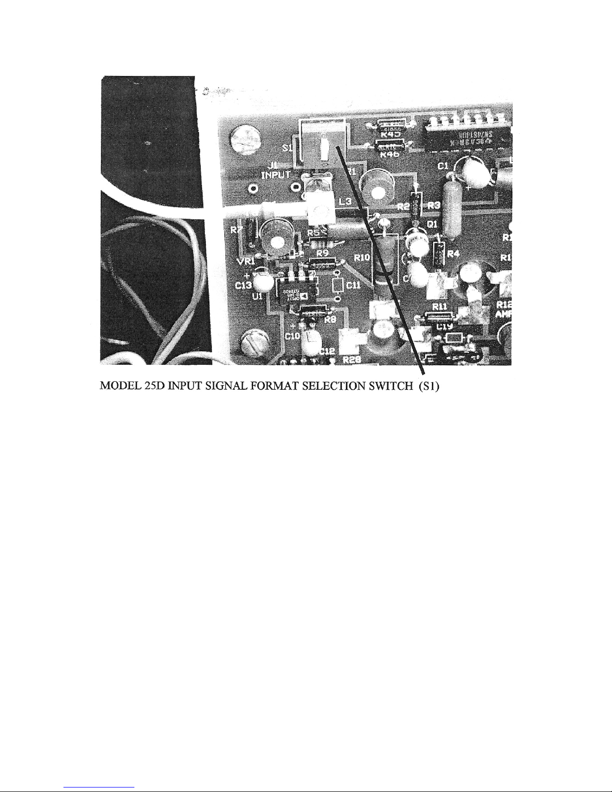
1) UP: Sets the input of the driver to accept a 0-1V input signal. Input
impedance is 50 ohms. Typically used for pulse selection systems using
model 305 synchronous countdown.
2) DOWN: Sets the input of the driver to accept a TTL logic level at the input
connector on the rear panel. Input impedance is 50 ohms.
To change input format switch, remove top cover on drive electronics with
system power off; select position for above position settings.
3
 Loading...