


Tome 3
Operating manual
System management- Operation administration- Installer data
M6501 IP PBX / M6540 IP PBX / NeXspan C-S-L
PS8149KENAA01
09/2004

.
Page 2 15/09/2004 PS8149KENAA01
Ce document est la propriété de EADS et ne doit pas être reproduit ou communiqué sans autorisation.
This document is the property of EADS and may not be copied or circulated without authorisation.
EADS Defence and Security Networks SAS
Rue JP Timbaud - Montigny Le Bretonneux
78063 St Quentin Yvelines Cedex - France
Tél : (0)1 34 60 80 00 - Fax : (0)1 34 60 72 41
Email : Technical-Support @eads.com

.
PS8149KENAA01 15/09/2004 Page 3
Ce document est la propriété de EADS et ne doit pas être reproduit ou communiqué sans autorisation.
This document is the property of EADS and may not be copied or circulated without authorisation.
CONTENTS
1. ABOUT THIS DOCUMENT...............................................................................11
1.1 PURPOSE OF THIS DOCUMENT.............................................................................11
1.2 TARGET AUDIENCE OF THIS DOCUMENT............................................................11
1.3 SCOPE OF THIS DOCUMENT..................................................................................11
1.4 CONTENTS OF THIS DOCUMENT...........................................................................11
1.5 TERMINOLOGY.........................................................................................................11
1.5.1 TERMS AND EXPRESSIONS............................................................................................ 11
1.5.2 ABBREVIATIONS .............................................................................................................. 11
1.6 REFERENCE DOCUMENTS .....................................................................................12
1.7 REMINDER CONCERNING THE LAW ON INFORMATION TECHNOLOGY ..........12
2. MENUS .............................................................................................................13
2.1 SYSTEM MANAGEMENT MENU..............................................................................13
2.2 OPERATION ADMINISTRATION MENU ..................................................................15
2.3 INSTALLER DATA MENU.........................................................................................16
2.4 DATA MANAGEMENT (MENU 2) .............................................................................17
3. SYSTEM MANAGEMENT (MENU 3) ...............................................................18
3.1 DATE AND TIME MANAGEMENT (MENU 3-1)........................................................19
3.1.1 DATE AND TIME DEFINITION .......................................................................................... 19
3.1.2 PROGRAMMING A CHANGE OF TIME............................................................................ 20
3.2 CARD MANAGEMENT (MENU 3-2)..........................................................................21
3.2.1 CARD TYPE AND STATUS............................................................................................... 21
3.2.2 PROCEDURE FOR INSTALLING A CARD....................................................................... 22
3.2.3 M6501L/R IP PBX CARDS................................................................................................. 24
3.2.4 M6504/M6540 CARDS ....................................................................................................... 26
3.2.5 XL/XS/XC CARDS.............................................................................................................. 35
3.3 MENU 3 -3). ...............................................................................................................53
3.3.1 HARDWARE CONFIGURATION (M6501 L/R IP PBX AND M6504/M6540 IP PBX)
(MENU 3-3-1)...................................................................................................................... 54
3.3.2 RECORD ANNOUNCEMENTS.......................................................................................... 57
3.3.3 SVF-BVF BOARD ACCESS CONFIGURATION (F6) (MENU 3-3-2) ............................... 59
3.3.4 GENERAL CHARACTERISTICS OF IVS IVB (F6) (MENU 3-3-3).................................... 60
3.4 TERMINAL MANAGEMENT (MENU 3-4)..................................................................61
3.4.1 TERMINAL CONNECTION ................................................................................................ 61
3.4.2 M6501L/R IP PBX (OCT4), M6504/M6540 IP PBX AND XL/XS/XC................................ 62

.
Page 4 15/09/2004 PS8149KENAA01
Ce document est la propriété de EADS et ne doit pas être reproduit ou communiqué sans autorisation.
This document is the property of EADS and may not be copied or circulated without authorisation.
3.5 PASSWORD MANAGEMENT (MENU 3-5)...............................................................65
3.5.1 M6501L/R IP PBX, M6504/M6540 IP PBX, XL, XS, XC.................................................... 65
3.5.2 COMPACT FORMAT WITH PASSWORD......................................................................... 68
3.6 PARAMETER MANAGEMENT (MENU 3-6) .............................................................69
3.7 MULTI-SITE MANAGEMENT (MENU 3-7)................................................................72
3.8 SOFTWARE LOCK MANAGEMENT (MENU 3-8) ....................................................72
3.8.1 UNLOCK SA FUNCTIONS (MENU 3-8-1)......................................................................... 73
3.8.2 DISPLAY SA FUNCTIONS (MENU 3-8-2)......................................................................... 76
3.9 INTEGR. BUFFER MANAGEMENT (MENU 3-9)......................................................79
3.9.1 PARAMETER MANAGEMENT (MENU 3-9-1) .................................................................. 79
3.9.2 RESET FLASH (MENU 3-9-2)............................................................................................ 81
4. OPERATION ADMINISTRATION (MENU 4)....................................................82
4.1 ADMINISTRATION PARAMETERS (MENU 4-1)......................................................83
4.2 OVERALL DISPLAY OF CHARGE COUNTERS (MENU 4-2) ....................................95
4.2.1 DISPLAY EXTENSION COUNTERS (MENU 4-2-1).......................................................... 95
4.2.2 DISPLAY TRUNK LINE COUNTERS (MENU 4-2-2)......................................................... 97
4.2.3 DISPLAY TRUNK GROUP COUNTERS (MENU 4-2-3).................................................... 98
4.2.4 DISPLAY OPERATOR CONSOLE COUNTERS (MENU 4-2-4) ....................................... 98
4.2.5 DISPLAY DEPARTMENT COUNTERS (MENU 4-2-5) ..................................................... 99
4.2.6 RESET COUNTERS (MENU 4-2-6) ................................................................................. 100
4.3 CHARGING OF INDIVIDUAL SUBSCRIBERS (MENU 4-3) ...................................102
4.4 LOGBOOK DISPLAY (MENU 4-4) ..........................................................................105
4.4.1 HARDWARE EVENTS RECORDED IN THE LOGBOOK............................................... 107
4.4.2 LOGICAL SECURITY BLOCKS ...................................................................................... 108
4.5 DELETE LOGBOOK (MENU 4-5) ...........................................................................109
4.6 DISPLAY STATUSES (MENU 4-6) .........................................................................110
4.6.1 STATUS OF EXTENSIONS (MENU 4-6-1)...................................................................... 111
4.6.2 STATUS OF EXTERNAL TRUNKS (MENU 4-6-2) ......................................................... 116
4.6.3 STATUS OF DYNAMIC TRUNK GROUPS (MENU 4-6-3).............................................. 118
4.6.4 STATUS OF DATA LINKS (MENU 4-6-4) ....................................................................... 119
4.6.5 MAINTENANCE STATUS (MENU 4-6-5) ........................................................................ 120
4.6.6 ROAMING STATUS OF MOBILES (MENU 4-6-6) .......................................................... 122
4.6.7 FILLING STATUS OF TABLES (MENU 4-6-7)................................................................ 124
4.6.8 STATUS OF TCP TUNNEL CONNECTIONS (MENU 4-6-8) .......................................... 125
4.6.9 STATUS OF INTEGRATED VOICE BOXES (MENU 4-6-9)............................................ 125
4.7 TRAFFIC OBSERVATION (MENU 4-7)...................................................................135
4.7.1 DEFINE TRUNK GROUP OBSERVATION (MENU 4-7-1).............................................. 136
4.7.2 DISPLAY TRUNK GROUP OBSERVATION (MENU 4-7-2) ........................................... 137
4.7.3 BASE STATION OBSERVATION (MENU 4-7-3)............................................................ 139
4.7.4 BASE STATION TRUNK OBSERVATION (MENU 4-7-4) .............................................. 140
4.7.5 MOBILE OBSERVATION (MENU 4-7-5)......................................................................... 141
4.7.6 RESET WIRELESS OBSERVATION (MENU 4-7-6)....................................................... 142
4.7.7 INTEGRATED VOICE BOX PARAMETERS (MENU 4-7-7)............................................ 143

.
PS8149KENAA01 15/09/2004 Page 5
Ce document est la propriété de EADS et ne doit pas être reproduit ou communiqué sans autorisation.
This document is the property of EADS and may not be copied or circulated without authorisation.
4.7.8 CAC SERVER MONITORING (MENU 4-7-8) .................................................................. 147
5. INSTALLER DATA (MENU 5) ........................................................................154
5.1 PROCESSOR ACCESS (MENU 5-1) ......................................................................155
5.1.1 FORMAT OF PAS FILES (MENU 5-1-1) ......................................................................... 155
5.1.2 DISPLAY OF PAS FILES (MENU 5-1-2) ......................................................................... 156
5.1.3 RESTART REQUEST (MENU 5-1-3) ............................................................................... 157
5.2 CONFIGURATION TRANSFER (MENU 5-2) ..........................................................160
5.2.1 SERIAL PORT CONFIGURATION TRANSFER ............................................................. 161
5.2.2 PARALLEL PORT CONFIGURATION TRANSFER ....................................................... 162
5.3 CONNECTION MANAGEMENT (MENU 5-3) NOT IN VALUES............................. 163
5.4 IDENTIFICATION (MENU 5-4) ................................................................................165
5.4.1 SOFTWARE IDENTIFICATION (MENU 5-4-1) ............................................................... 166
5.4.2 HARDWARE IDENTIFICATION (MENU 5-4-2) .............................................................. 169
5.4.3 DISPLAY DIGITAL SET NAMES (MENU 5-4-2 ON F1/F2 AND 5-4-3 ON F6) .............. 171
5.4.4 MANAGEMENT OF DIGITAL SET NAMES (MENU 5-4-3 ON F1/F2
AND 5-4-4 ON F6) ............................................................................................................ 173
5.5 TONE AND ANNOUNCEMENT DEFINITION (MENU 5-5) .....................................174
5.5.1 TONE AND ANNOUNCEMENT DEFINITION (MENU 5-5-1).......................................... 176
5.5.2 ANNOUNCEMENTS (MENU 5-5-2) ................................................................................. 184
5.5.3 DEFINITION OF SPOKEN LANGUAGES (MENU 5-5-3)................................................ 196
5.5.4 ALLOCATION OF TONES TO LANGUAGES (MENU 5-5-4) ......................................... 197
5.5.5 COMPANY/DEPARTMENT SPECIFIC TONES (MENU 5-5-4)....................................... 199
5.5.6 DEFINITION OF DIRECT ACCESS MESSAGES (MENU 5-5-6).................................... 201
5.5.7 DISPLAY DEFINABLE TONES (MENU 5-5-7)................................................................ 202
5.5.8 EXTENNAL MUSIQUE LEVEL ADJUST. (MENU 5-5-8) (F1 AND F6) .......................... 204
5.6 SIGNALLING MANAGEMENT (MENU 5-6)............................................................205
5.6.1 SIGNALLING ACTIVATION (MENU 5.6.1)...................................................................... 205
5.6.2 NON ISDN SIGNALLING PARAMTERS (MENU 5-6-2).................................................. 209
5.6.3 ISDN SIGNALLING PARAMETERS (MENU 5.6.3)......................................................... 213
5.6.4 INITIALIZE A SIGNALLING TYPE (MENU 5-6-4)........................................................... 216
5.6.5 RECORDING PARAMETERS (MENU 5-6-5) .................................................................. 217
5.6.6 IP SIGNALING PARAMETERS (MENU 5-6-6)................................................................ 219
5.7 ALARM CONFIGURATION (MENU 5-7).................................................................221
5.7.1 INDIVIDUALIZED CONFIGURATION (MENU 5-7-1)...................................................... 221
5.7.2 GLOBAL RESET (MENU 5-7-2) ...................................................................................... 224

.
Page 6 15/09/2004 PS8149KENAA01
Ce document est la propriété de EADS et ne doit pas être reproduit ou communiqué sans autorisation.
This document is the property of EADS and may not be copied or circulated without authorisation.
FIGURES
Figure 1: Menu 3 (System management - F1) ...................................................................................... 18
Figure 2: Menu 3 (System management - F6) ...................................................................................... 18
Figure 3: Time and date management .................................................................................................. 19
Figure 4: Date and time management (continued)................................................................................ 20
Figure 5: Card management (M6501L/R) ............................................................................................. 24
Figure 6: Card management (M6501L/R) (continued) .......................................................................... 24
Figure 7: Card management (M6504/M6540)....................................................................................... 26
Figure 8: "Equipment" card management (M6504/M6540)................................................................... 26
Figure 9: "Equipment" card management (M6504/M6540) (continued) ............................................... 27
Figure 10: "Equipment" card management (M6504/M6540) (continued) ............................................. 27
Figure 11: "Multibus" card management (M6504/6540) ....................................................................... 30
Figure 12: "Multibus" card management (M6504/6540) (continued) .................................................... 30
Figure 13: Link selection ....................................................................................................................... 33
Figure 14: Link selection (continued) .................................................................................................... 34
Figure 15: Link selection (continued) .................................................................................................... 34
Figure 16: Card management (XL, XS and XC)................................................................................... 35
Figure 17: Common boards management (XL)..................................................................................... 36
Figure 18: Common boards management (XL) (continued) ................................................................. 37
Figure 19: Common boards management (XL) (continued) ................................................................. 37
Figure 20: Common boards management (XL) (continued) ................................................................. 38
Figure 21: Common boards management (XL) (continued) ................................................................. 38
Figure 22: Common boards management (XL) (continued) ................................................................. 39
Figure 23: Card management (XS) ....................................................................................................... 40
Figure 24: XL hardware and software configurations – Migration (menu 3-2-2) .................................. 42
Figure 25: XS hardware and software configurations – Migration (menu 3-2-2) .................................. 44
Figure 26: XC hardware and software configurations – Migration (menu 3-2-2).................................. 47
Figure 27: IP board parameters management (menu 3-2-3) ................................................................ 49
Figure 28: IP card selection................................................................................................................... 50
Figure 29: ISDN board switches status (menu 3-2-4)........................................................................... 52
Figure 30: Configuration and recording (Menu 3-3) (F1) ...................................................................... 53
Figure 31: SVF-BVF configuration (Menu 3-3) (F6) ............................................................................. 53
Figure 32: Hardware configuration (M6501L/R IP PBX) ....................................................................... 54
Figure 33: Hardware configuration (M6504/M6540) ............................................................................. 56
Figure 34: Record announcements....................................................................................................... 57
Figure 35: SVF-BVF board access configuration (F6) (Menu 3-3-2) .................................................... 59
Figure 36 : Displaying IVS general characteristics (F6) (Menu 3-3-3)................................................. 60
Figure 37: Terminal management ......................................................................................................... 62
Figure 38: Menu 3-5 (Password management F1/F2/F6)..................................................................... 65
Figure 39: Compact format with password management ..................................................................... 68
Figure 40: Menu 3-6 (Parameter management).................................................................................... 69
Figure 41: Menu 3-8 (Software lock management)............................................................................... 72

.
PS8149KENAA01 15/09/2004 Page 7
Ce document est la propriété de EADS et ne doit pas être reproduit ou communiqué sans autorisation.
This document is the property of EADS and may not be copied or circulated without authorisation.
Figure 42: Selection of the SA function ................................................................................................. 73
Figure 43: Unlock hospital/hotel ............................................................................................................ 75
Figure 44: Display SA functions (F6)..................................................................................................... 76
Figure 45: Display SA functions (F6) (continued) ................................................................................. 77
Figure 46: Display SA functions (F6) (continued) ................................................................................. 77
Figure 47: Display SA functions (F6) (continued) ................................................................................. 78
Figure 48: Menu 3-9 (Integrated buffer management).......................................................................... 79
Figure 49: Integr. buffer parameter management (1)............................................................................ 79
Figure 50: Integr. buffer parameter management (2)............................................................................ 79
Figure 51: Reset flash ........................................................................................................................... 81
Figure 52: Administration password ...................................................................................................... 82
Figure 53: Menu 4 (Operation administration). ..................................................................................... 82
Figure 54: Menu 4-1 (Administration parameters). ............................................................................... 83
Figure 55: Administration parameters (continued)................................................................................85
Figure 56: Administration parameters (continued)................................................................................87
Figure 57: Administration parameters (continued)................................................................................89
Figure 58: Administration parameters (continued)................................................................................91
Figure 59: Administration parameters (continued - alarm validation on F6) ......................................... 92
Figure 60: Administration parameters (continued - alarm validation on F1) ......................................... 93
Figure 61: Administration parameters (continued - alarm validation on F2) ......................................... 93
Figure 62: Menu 4-2 (Overall charge data) ........................................................................................... 95
Figure 63: Display extension meters ..................................................................................................... 95
Figure 64: Extension counters............................................................................................................... 96
Figure 65: Display of trunk line counters (F2) ....................................................................................... 97
Figure 66: Display of trunk group counters (F2).................................................................................... 98
Figure 67: Display operator console counters....................................................................................... 98
Figure 68: Display department counters ............................................................................................... 99
Figure 69: Selection of counters to be reset ....................................................................................... 100
Figure 70: Reset counter password .................................................................................................... 100
Figure 71: Message indicating that the counters have been reset ..................................................... 101
Figure 72: Menu 4-3 (Directory number selection) ............................................................................. 102
Figure 73: Charging subscriber 28 ...................................................................................................... 102
Figure 74: Menu 4-4 (Logbook)........................................................................................................... 105
Figure 75: Password for deleting the logbook..................................................................................... 109
Figure 76: Delete logbook ................................................................................................................... 109
Figure 77: Menu 4-6 (Display statuses). ............................................................................................. 110
Figure 78: Status of extensions........................................................................................................... 111
Figure 79: Selection of a status to monitor.......................................................................................... 111
Figure 80: Display extensions (F1) (any status).................................................................................. 112
Figure 81: Display extensions (F6) (any status).................................................................................. 112
Figure 82: IP subscribers status - selection ........................................................................................ 113
Figure 83: IP subscribers status - display non-connected applicative sessions................................. 114
Figure 84: IP subscribers status - display connected applicative sessions ........................................ 114
Figure 85: Selection of a status to monitor.......................................................................................... 116
Figure 86: External trunk lines on the trunk group .............................................................................. 117
Figure 87: Selection of a status to monitor.......................................................................................... 118
Figure 88: Status of dynamic trunk groups ......................................................................................... 118

.
Page 8 15/09/2004 PS8149KENAA01
Ce document est la propriété de EADS et ne doit pas être reproduit ou communiqué sans autorisation.
This document is the property of EADS and may not be copied or circulated without authorisation.
Figure 89: Status of data links (F6) ..................................................................................................... 119
Figure 90: Status of data links (F6) (continued) .................................................................................. 119
Figure 91: Selection of a status to monitor.......................................................................................... 120
Figure 92: Display any maintenance status ........................................................................................ 121
Figure 93: Display any maintenance status (continued) ..................................................................... 121
Figure 94: Mobile localisation status ................................................................................................... 122
Figure 95: Mobile localisation (menu 4-6-6-1)..................................................................................... 122
Figure 96: Mobile localisation (cell basis) (menu 4-6-6-2) .................................................................. 123
Figure 97: Mobiles localised on cell xxxxxx ........................................................................................ 123
Figure 98: Filling status of tables......................................................................................................... 124
Figure 99: Filling status of tables (cont.) ............................................................................................. 124
Figure 100: Status of TCP tunnel connections.................................................................................... 125
Figure 101: Status of integrated voice boxes...................................................................................... 125
Figure 102: Overall view of voice mailboxes....................................................................................... 126
Figure 103: Displaying voice mailboxes from a directory number ...................................................... 126
Figure 104: Displaying voice mailboxes belonging to the same service class ................................... 127
Figure 105: Displaying voice mailboxes depending on operating mode............................................. 127
Figure 106: Displaying voice mailboxes by status .............................................................................. 128
Figure 107: Selecting a voice mailbox................................................................................................. 130
Figure 108: Displaying voice mailbox messages ................................................................................ 130
Figure 109: View messages involved in audit ..................................................................................... 132
Figure 110: Display general characteristics ........................................................................................ 133
Figure 111: Displaying voicemail busy statistics ................................................................................. 134
Figure 112: Displaying voicemail busy statistics (cont.)...................................................................... 134
Figure 113: Menu 4-7 (Traffic observation)......................................................................................... 135
Figure 114: Define trunk group observation........................................................................................ 136
Figure 115: Display trunk group observation ...................................................................................... 137
Figure 116: Observation of trunk group table...................................................................................... 138
Figure 117: Base station observation.................................................................................................. 139
Figure 118: Base station observation table......................................................................................... 139
Figure 119: Selection of trunk group to be observed .......................................................................... 140
Figure 120: Observation of the selected trunk group.......................................................................... 140
Figure 121: Mobile observation table .................................................................................................. 141
Figure 122: Rest wireless observation ................................................................................................ 142
Figure 123: Integrated voice box parameters ..................................................................................... 143
Figure 124: Audit start-up criteria ........................................................................................................ 144
Figure 125: Message deletion criteria ................................................................................................. 145
Figure 126: Reset voice mailbox flash ................................................................................................ 146
Figure 127: CAC server monitoring..................................................................................................... 147
Figure 128: Display flows towards other centres ................................................................................ 147
Figure 129: Display flows by CAC class ............................................................................................. 149
Figure 130: Reset the centre counters................................................................................................ 150
Figure 131: Reset class counters........................................................................................................ 152
Figure 132 : CAC servers status ......................................................................................................... 153
Figure 133: Password for access to installer data .............................................................................. 154
Figure 134: Menu 5 (Installer data). .................................................................................................... 154
Figure 135: Menu 5-1 (Processor access).......................................................................................... 155

.
PS8149KENAA01 15/09/2004 Page 9
Ce document est la propriété de EADS et ne doit pas être reproduit ou communiqué sans autorisation.
This document is the property of EADS and may not be copied or circulated without authorisation.
Figure 136: Format of PAS files .......................................................................................................... 155
Figure 137: Display of PAS files.......................................................................................................... 156
Figure 138: Restart request................................................................................................................. 157
Figure 139: Menu 5-2 (Configuration transfer).................................................................................... 160
Figure 140: Serial port configuration transfer...................................................................................... 161
Figure 141: Parallel transfer of the configuration ................................................................................ 162
Figure 142: Menu 5-3 (Connection management) .............................................................................. 163
Figure 143: Identification (F1) ............................................................................................................. 165
Figure 144: Identification (F6) ............................................................................................................. 165
Figure 145: Software identification (F1) .............................................................................................. 166
Figure 146: Software identification (F2) .............................................................................................. 167
Figure 147: Software identification (XL) .............................................................................................. 168
Figure 148: Hardware identification (F6)............................................................................................. 169
Figure 149: Hardware identification (example of an XL cabinet) ........................................................ 169
Figure 150: Hardware identification (example of an XL cabinet) ........................................................ 170
Figure 151: Display digital set names ................................................................................................. 171
Figure 152: Display digital set names (continued) .............................................................................. 171
Figure 153: Display digital set names (continued) .............................................................................. 172
Figure 154: Display digital set names (end)........................................................................................ 172
Figure 155: Modification of digital set names...................................................................................... 173
Figure 156: Voice cards of the various PBX families (F1/F2) ............................................................. 174
Figure 157: Menu 5-5 (Tone and announcement definition - F1). ...................................................... 174
Figure 158: Menu 5-5 (Tone and announcement definition - F2). ...................................................... 175
Figure 159: Menu 5-5 (Tone and announcement definition - F6). ...................................................... 175
Figure 160: Selection of tone type....................................................................................................... 176
Figure 161: Normal dial tone ............................................................................................................... 180
Figure 162: Busy tone ......................................................................................................................... 183
Figure 163: Call accepted tone ........................................................................................................... 183
Figure 164: Menu 5-5-2 (Announcements on F1)............................................................................... 184
Figure 165: Menu 5-5-2 (Announcements on F2)............................................................................... 184
Figure 166: Summary of voice cards installed in F1/F2 PBXs............................................................ 185
Figure 167: Menu 5-5-2 (Announcements on XL/XS/XC)................................................................... 185
Figure 168: Summary of voice cards installed in F6 PBXs ................................................................. 185
Figure 169: Select music on hold ........................................................................................................ 186
Figure 170: Record RAM message..................................................................................................... 186
Figure 171: Voice card recording duration .......................................................................................... 186
Figure 172: Listen to ROM messages................................................................................................. 187
Figure 173: Announcement message loading connection .................................................................. 188
Figure 174: View announcements (F1) ............................................................................................... 189
Figure 175: View announcements (F6) ............................................................................................... 189
Figure 176: Announcement distribution .............................................................................................. 191
Figure 177: Observe counters (F6) ..................................................................................................... 192
Figure 178: Reset counters (F6) ......................................................................................................... 193
Figure 179: Record announcements................................................................................................... 194
Figure 180: Definition of spoken languages........................................................................................ 196
Figure 181: Allocation of tones to languages ...................................................................................... 197
Figure 182: Allocation of tones to languages (continued)................................................................... 197

.
Page 10 15/09/2004 PS8149KENAA01
Ce document est la propriété de EADS et ne doit pas être reproduit ou communiqué sans autorisation.
This document is the property of EADS and may not be copied or circulated without authorisation.
Figure 183: Specific tone (single-company)........................................................................................ 199
Figure 184: Company/department specific tones................................................................................ 200
Figure 185: Company/department specific tones (cont.) .................................................................... 200
Figure 186: Definition of direct access messages .............................................................................. 201
Figure 187: Display of definable tones in single-company configuration............................................ 202
Figure 188: Display of definable tones in multi-company configuration.............................................. 203
Figure 189: Adjust external music level (F1)....................................................................................... 204
Figure 190: Adjust external music level (F6)....................................................................................... 204
Figure 191: Menu 5-6 (Signalling management)................................................................................. 205
Figure 192: Signalling activation ......................................................................................................... 205
Figure 193: Signalling for digital TRK.................................................................................................. 206
Figure 194: Signalling for analogue TRK ............................................................................................ 206
Figure 195: Signalling for tie-line......................................................................................................... 207
Figure 196: Signalling for ISDN:T0...................................................................................................... 207
Figure 197: Signalling for ISDN:T2...................................................................................................... 208
Figure 198: Signalling for voice IP....................................................................................................... 208
Figure 199: Non ISDN signalling parameters...................................................................................... 209
Figure 200: Non ISDN signalling parameters (continued) .................................................................. 210
Figure 201: Non ISDN signalling parameters (continued) .................................................................. 211
Figure 202: Non ISDN signalling parameters (end) ............................................................................ 211
Figure 203: ISDN signalling parameters ............................................................................................. 213
Figure 204: ISDN signalling parameters (continued) .......................................................................... 213
Figure 205: ISDN signalling parameters (continued) .......................................................................... 214
Figure 206: ISDN signalling parameters (continued) .......................................................................... 214
Figure 207: Initialise a signalling type ................................................................................................. 216
Figure 208: R2 Standard recorder parameters ................................................................................... 217
Figure 209: IP signalling parameters .................................................................................................. 219
Figure 210: Alarm configuration .......................................................................................................... 221
Figure 211: Configure the alarms: selection ....................................................................................... 221
Figure 212: Alarm configuration .......................................................................................................... 223
Figure 213: Configure the alarms: global reset ................................................................................... 224

.
PS8149KENAA01 15/09/2004 Page 11
Ce document est la propriété de EADS et ne doit pas être reproduit ou communiqué sans autorisation.
This document is the property of EADS and may not be copied or circulated without authorisation.
1. ABOUT THIS DOCUMENT
1.1 PURPOSE OF THIS DOCUMENT
This document describes the MMCs of the PBX from software release 3.2, with the
exception of the MMCs relating to data transmission which are dealt with in a separate
manual.
1.2 TARGET AUDIENCE OF THIS DOCUMENT
This document is intended for installation technicians who configure the PBX and
implement the telephone features introduced by this software release.
1.3 SCOPE OF THIS DOCUMENT
This document applies to M6501 IP PBX, M6501L IP PBX, M6501R IP PBX, M6504 IP
PBX, M6540 IP PBX, NeXspan C-S-L running software release 3.2 or later.
1.4 CONTENTS OF THIS DOCUMENT
This document describes all the means available to the operator for management of the
M6501 IP PBX, M6501L IP PBX, M6501R IP PBX, M6504 IP PBX, M6540 IP PBX and
NeXspan C-S-L from an operating terminal.
The set of Man Machine Commands (MMCs) described in this manual enable you to
operate and manage M6501 IP PBX, M6501L IP PBX, M6501R IP PBX, M6504 IP PBX,
M6540 IP PBX and NeXspan C-S-L.
This manual is composed of chapters ordered according to the tree structure of the MMCs
as presented on the screen of the operating console.
1.5 TERMINOLOGY
1.5.1 TERMS AND EXPRESSIONS
Not applicable.
1.5.2 ABBREVIATIONS
F1 PBX range comprising M6501 L/R IP PBX
F2 PBX range comprising M6504 IP PBX, M6504 L IP PBX, M6540 IP PBX
F 5 Software application (Call Manager)
F6 PBX range comprising NeXspan C (XC), NeXspan S (XS) and NeXspan L (XL)

.
Page 12 15/09/2004 PS8149KENAA01
Ce document est la propriété de EADS et ne doit pas être reproduit ou communiqué sans autorisation.
This document is the property of EADS and may not be copied or circulated without authorisation.
1.6 REFERENCE DOCUMENTS
The information contained in this manual refers to the following documents:
♦ M6501L/R IP PBX Installation manual
♦ M6504 Installation manual
♦ M6504L IP PBX Installation manual
♦ M6540 IP PBX Installation manual
♦ NeXspan range (XL/XS/XC) Installation and Maintenance Manual
♦ Telephone sets manual
1.7 REMINDER CONCERNING THE LAW ON INFORMATION
TECHNOLOGY
The user is reminded that commissioning PBXs in the workplace must comply with
the recommendations of the IT law in force.
The user's attention is also drawn to any clauses applicable in laws relating to the
confidentiality of calls transmitted by means of telecommunications.
.
PS8149KENAA01 15/09/2004 Page 13
Ce document est la propriété de EADS et ne doit pas être reproduit ou communiqué sans autorisation.
This document is the property of EADS and may not be copied or circulated without authorisation.
2. MENUS
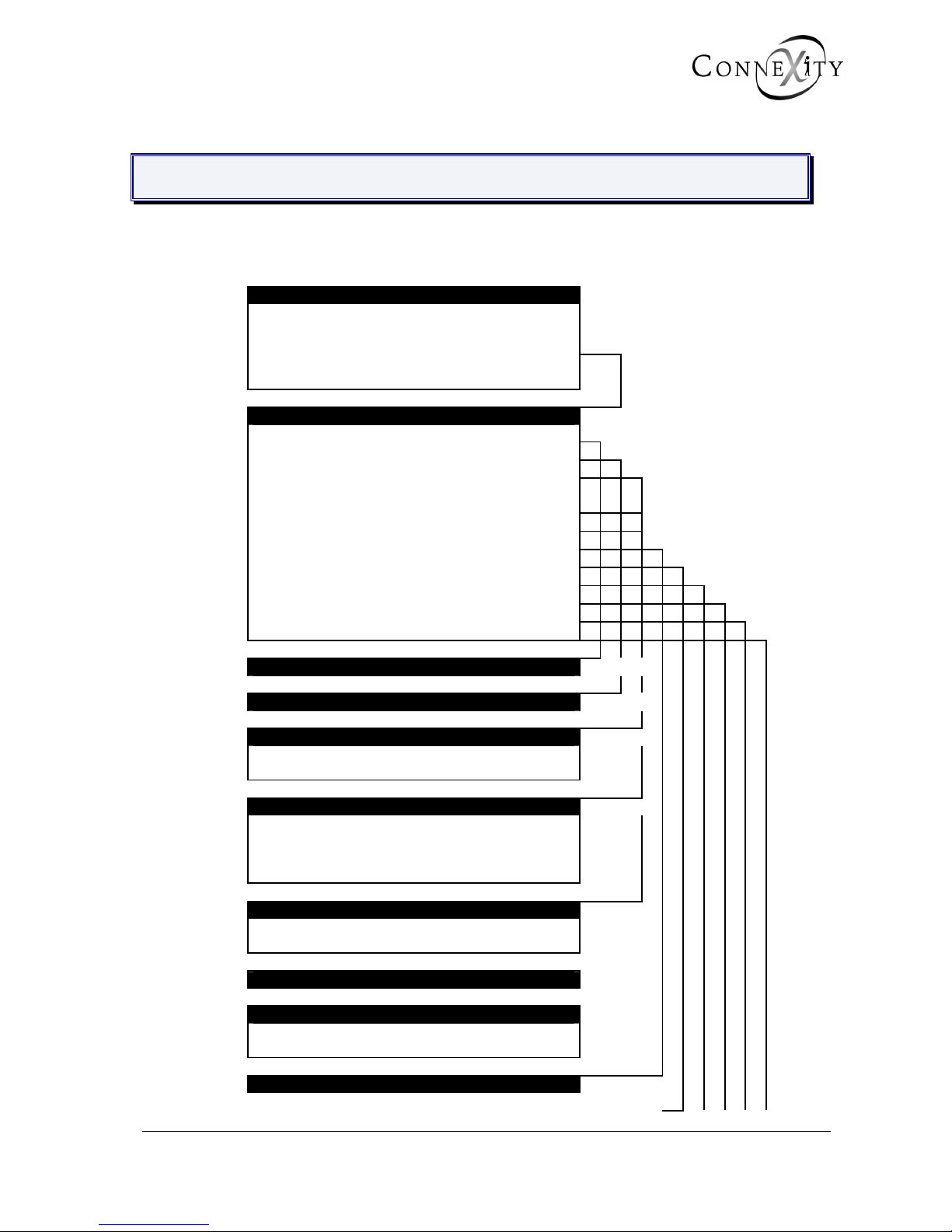
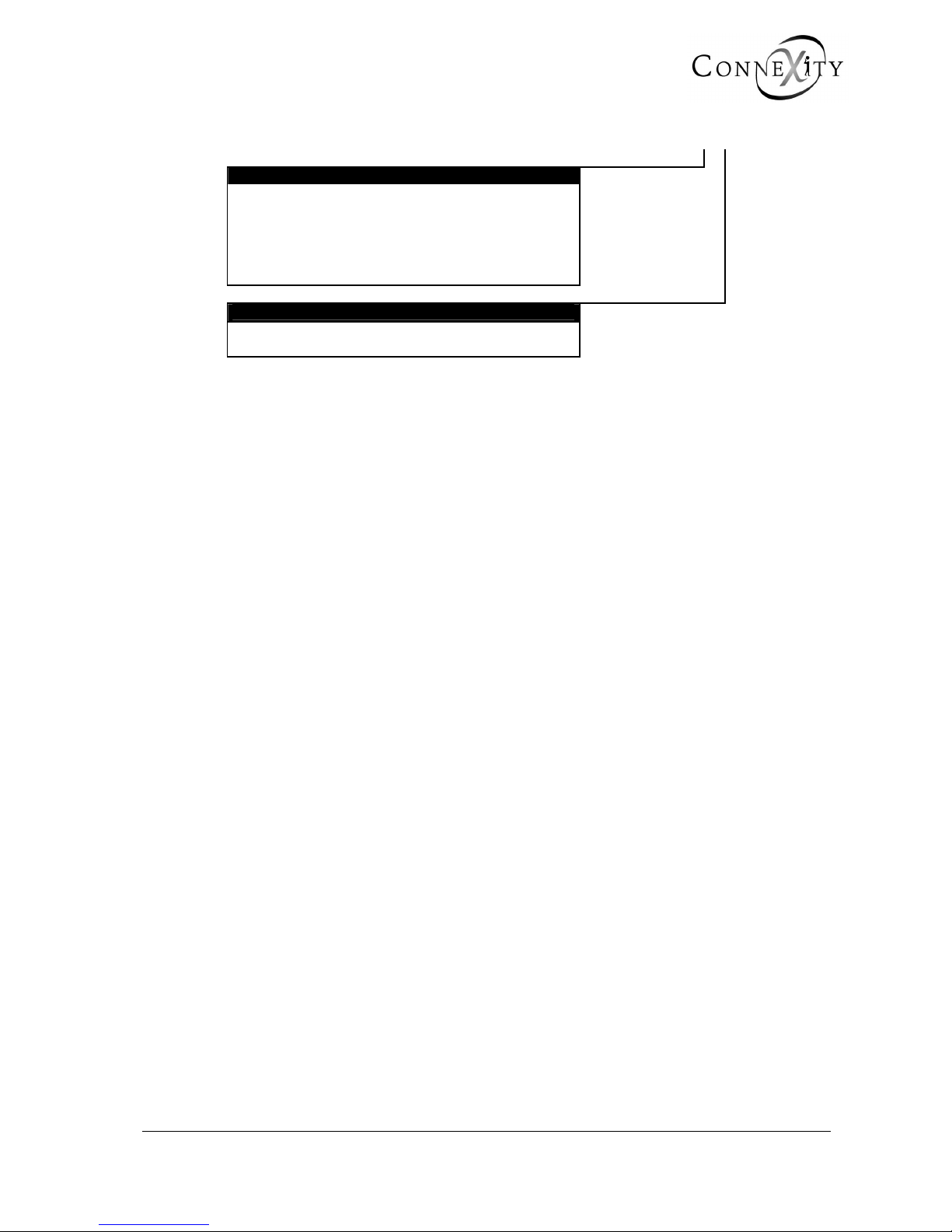
2.1 SYSTEM MANAGEMENT MENU
PBX MANAGEMENT
1 - TELEPHONY MANAGEMENT
2 - DATA MANAGEMENT
3 - SYSTEM MANAGEMENT
4 - OPERATION ADMINISTRATION
5 - INSTALLER DATA Password "INSTA"
SYSTEM MANAGEMENT
1 – DATE AND TIME MANAGEMENT
2 – CARD MANAGEMENT
3 - CONFIGURATION AND RECORDING (F1)
3 – HARDWARE CONFIGURATION MANAGEMENT
(F2)
3 - FVS-BVS CONFIGURATION (F6)
4 – TERMINAL MANAGEMENT
5 – PASSWORD MANAGEMENT
6 – PARAMETER MANAGEMENT
7 – MULTI-SITE MANAGEMENT
8 – SOFTWARE LOCK MANAGEMENT
9 – INTEGRAT. BUFFER MANAGEMENT
MANAGEMENT OF DATE AND TIME Menu 3-1
CARD MANAGEMENT (F1) Menu 3-2
CARD MANAGEMENT (F2) Menu 3-2
1 - EQUIPMENT CARD SLOTS
2 - MULTIBUS SLOTS
CARD MANAGEMENT (F6) Menu 3-2
1 – COMMON BOARDS MANAGEMENT
2 - MOTHER BOARD MANAGEMENT - MIGRATION
3 - IP BOARD PARAMETERS MANAGEMENT
4 - ISDN BOARD SWITCHES STATUS
CONFIGURATION AND RECORDING (F1) Menu 3-3
1 - HARDWARE CONFIGURATION
2 - BVF: RECORDING MESSAGES
HARDWARE CONFIGURATION MANAGEMENT (F2) Menu 3-3
FVS-BVS CONFIGURATION (F6) Menu 3-3
1 - SVF-BVF: RECORDING MESSAGES
2 - SVF-BVF BOARD ACCESS CONFIGURATION
TERMINAL MANAGEMENT Menu 3-4
.
Page 14 15/09/2004 PS8149KENAA01
Ce document est la propriété de EADS et ne doit pas être reproduit ou communiqué sans autorisation.
This document is the property of EADS and may not be copied or circulated without authorisation.
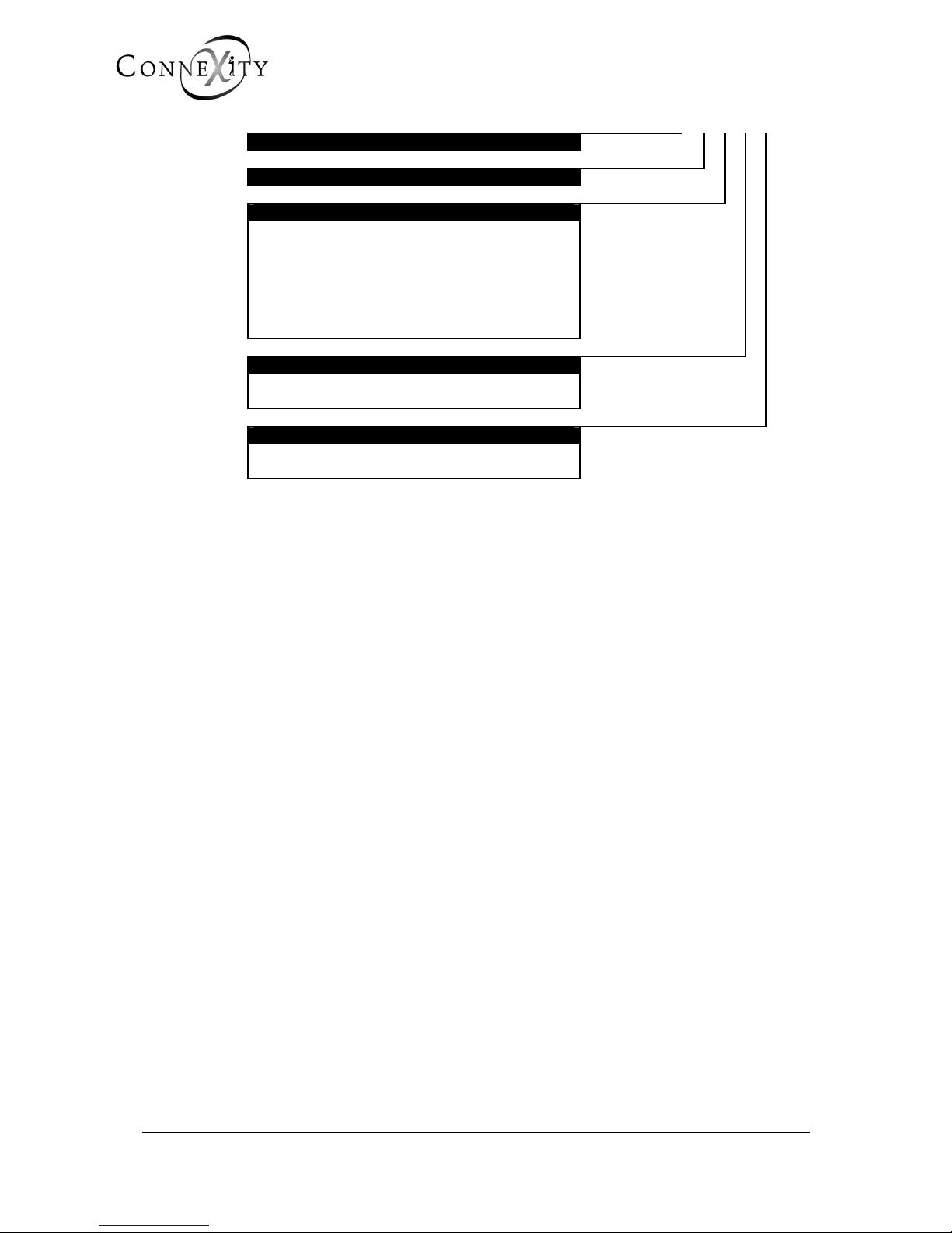
MANAGEMENT PASSWORD Menu 3-5
PARAMETER MANAGEMENT Menu 3-6
MULTI-SITE MANAGEMENT Menu 3-7
1 - DEFINITION OF CENTERS AND SITES
2 – MESSAGE ROUTING
3 – CIRCUIT MANAGEMENT
4 – PERMANENT LINK MANAGEMENT
5 - RESOURCES ON OTHER SITES
6 - SITE CONFIGURATION TOOL
7 – VOICE OVER IP PARAMETERS
SOFTWARE LOCK MANAGEMENT Menu 3-8
1 – UNLOCK SA FUNCTIONS
2 – DISPLAY SA FUNCTIONS
INTEGR. BUFFER MANAGEMENT Menu 3-9
1 – PARAMETER MANAGEMENT
2 – RESET FLASH
.
PS8149KENAA01 15/09/2004 Page 15
Ce document est la propriété de EADS et ne doit pas être reproduit ou communiqué sans autorisation.
This document is the property of EADS and may not be copied or circulated without authorisation.
2.2 OPERATION ADMINISTRATION MENU
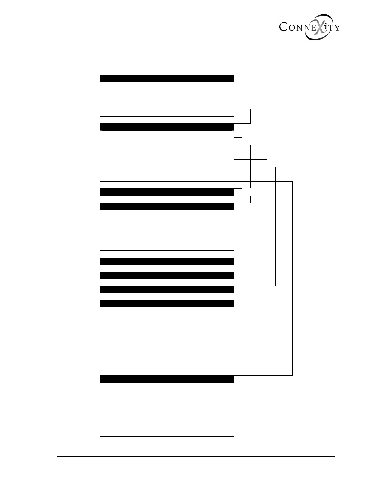
PBX MANAGEMENT
1 - TELEPHONY MANAGEMENT
2 - DATA MANAGEMENT
3 - SYSTEM MANAGEMENT
4 - OPERATION ADMINISTRATION
5 - INSTALLER DATA Password "INSTA"
OPERATION ADMINISTRATION
1 – ADMINISTRATION PARAMETERS
2 - OVERALL DISPLAY OF CHARGE COUNTERS
3 – CHARGING OF INDIVIDUAL SUBSCRIBERS
4 - LOGBOOK DISPLAY
5 - DELETE LOGBOOK
6 – DISPLAY STATUSES
7 – TRAFFIC OBSERVATION
ADMINISTRATION PARAMETERS Menu 4-1
OVERALL DISPLAY OF CHARGE COUNTERS Menu 4-2
1 – DISPLAY EXTENSION COUNTERS
2 – DISPLAY TRUNK LINE COUNTERS
3 – DISPLAY TRUNK GROUP COUNTERS
4 – DISPLAY OPERATOR CONSOLE COUNTERS
5 – DISPLAY DEPARTMENT COUNTERS
6 – RESET COUNTERS
CHARGING OF INDIVIDUAL SUBSCRIBERS Menu 4-3
LOGBOOK Menu 4-4
DELETE LOGBOOK Menu 4-5
DISPLAY STATUSES Menu 4-6
1 – STATUS OF EXTENSIONS
2 – STATUS OF EXTERNAL TRUNKS
3 – STATUS OF DYNAMIC TRUNK GROUPS
4 – STATUS OF DATA LINKS
5 – MAINTENANCE STATUS
6 – ROAMING STATUS OF MOBILES
7 – FILLING STATUS OF TABLES
8 – STATUS OF TUNNEL TCP CONNECTIONS
9 – STATUS OF INTEGRATED VOICE BOXES
TRAFFIC OBSERVATION Menu 4-7
1 – DEFINE TRUNK GROUP OBSERVATION
2 – DISPLAY TRUNK GROUP OBSERVATION
3 – BASE STATION OBSERVATION
4 – BASE STATION TRUNK OBSERVATION
5 – MOBILE OBSERVATION
6 - RESET WIRELESS OBSERVATION
7 – INTEGRATED VOICE BOX PARAMETERS
8 - CAC SERVER MONITORING
.
Page 16 15/09/2004 PS8149KENAA01
Ce document est la propriété de EADS et ne doit pas être reproduit ou communiqué sans autorisation.
This document is the property of EADS and may not be copied or circulated without authorisation.
2.3 INSTALLER DATA MENU
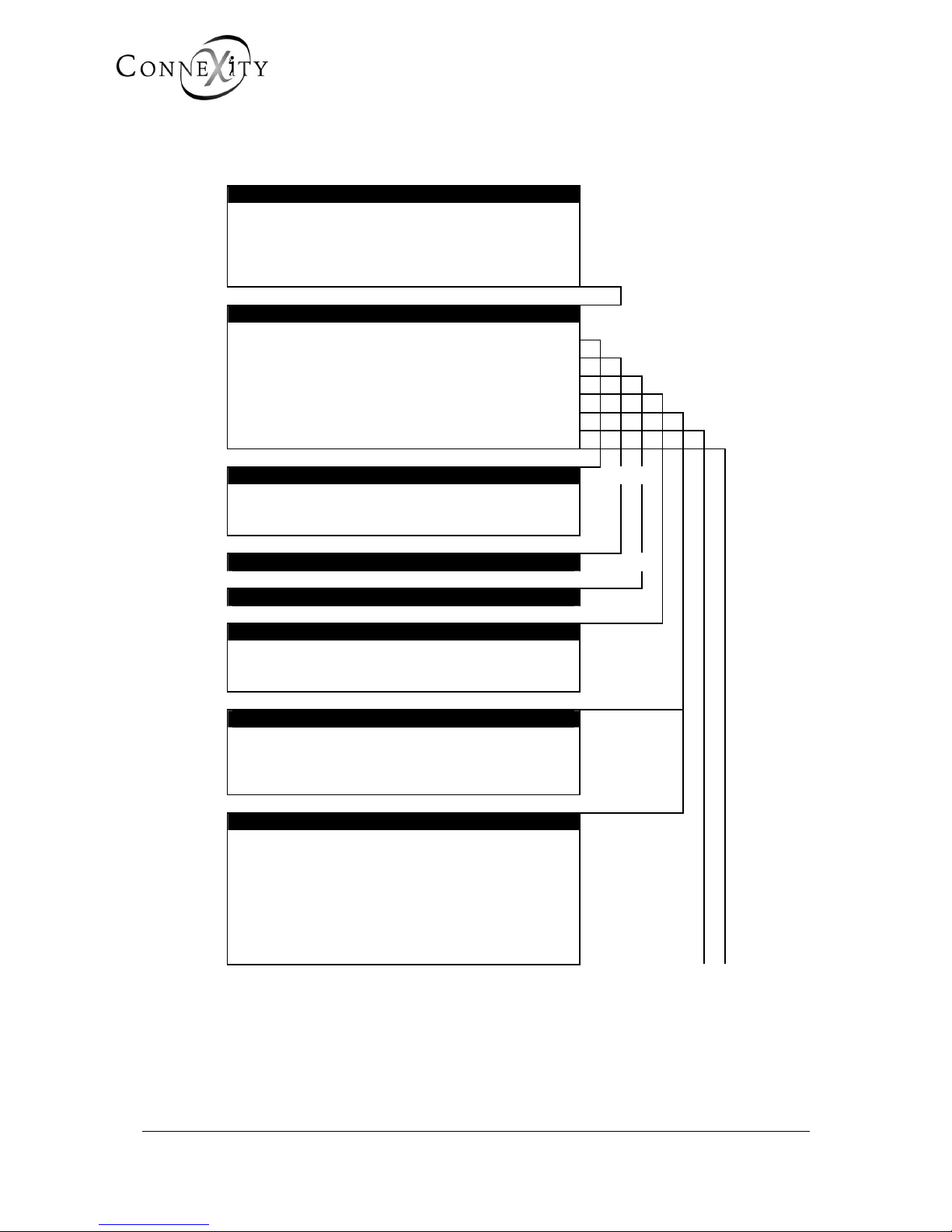
PBX MANAGEMENT
1 - TELEPHONY MANAGEMENT
2 - DATA MANAGEMENT
3 - SYSTEM MANAGEMENT
4 - OPERATION ADMINISTRATION
5 - INSTALLER DATA Password "INSTA"
INSTALLER DATA
1 – PROCESSOR ACCESS
2 – CONFIGURATION TRANSFER
3 – CONNECTION MANAGEMENT
4 – IDENTIFICATION
5 – TONE AND ANNOUNCEMENT DEFINITION
6 – SIGNALLING MANAGEMENT
7 – ALARM CONFIGURATION
PROCESSOR ACCESS Menu 5-1
1 – FORMAT OF PAS FILES
2 – DISPLAY OF PAS FILES
3 – RESTART REQUEST
CONFIGURATION TRANSFER Menu 5-2
CONNECTION MANAGEMENT Menu 5-3
IDENTIFICATION (F1) Menu 5-4
1 – SOFTWARE IDENTIFICATION
2 – DISPLAY DIGITAL SET NAMES
3 – MANAGEMENT OF DIGITAL SET NAMES
IDENTIFICATION (F6) Menu 5-4
1 – SOFTWARE IDENTIFICATION
2 - HARDWARE IDENTIFICATION
3 – DISPLAY DIGITAL SET NAMES
4 – MANAGEMENT OF DIGITAL SET NAMES
TONE AND ANNOUNCEMENT DEFINITION Menu 5-5
1 – TONE DEFINITION
2 – ANNOUNCEMENTS
3 – DEFINITION OF SPOKEN LANGUAGES
4 – ALLOCATION OF TONES TO LANGUAGES
5 – COMPANY/DEPARTMENT SPECIFIC TONES
6 – DEFINITION OF DIRECT ACCESS MESSAGES
7 – DISPLAY DEFINABLE TONES
8 – EXTENNAL MUSIQUE LEVEL ADJUST.
.
PS8149KENAA01 15/09/2004 Page 17
Ce document est la propriété de EADS et ne doit pas être reproduit ou communiqué sans autorisation.
This document is the property of EADS and may not be copied or circulated without authorisation.
SIGNALlING MANAGEMENT Menu 5-6
1 - SIGNALLING ACTIVATION
2 - NON ISDN SIGNALLING PARAMETERS
3 - ISDN SIGNALLING PARAMETERS
4 - INITIALIZE A SIGNALLING TYPE
5 - RECORDING PARAMETERS
6 - IP SIGNALLING PARAMETERS
ALARM CONFIGURATION
Menu 5-7
1 - INDIVIDUALIZED CONFIGURATION
2 - GLOBAL RESET
2.4 DATA MANAGEMENT (MENU 2)
Since the data management functions are of great importance, they are not described in
this manual, and are dealt with in a separate manual (reference PS8720ENJAA01).

.
Page 18 15/09/2004 PS8149KENAA01
Ce document est la propriété de EADS et ne doit pas être reproduit ou communiqué sans autorisation.
This document is the property of EADS and may not be copied or circulated without authorisation.
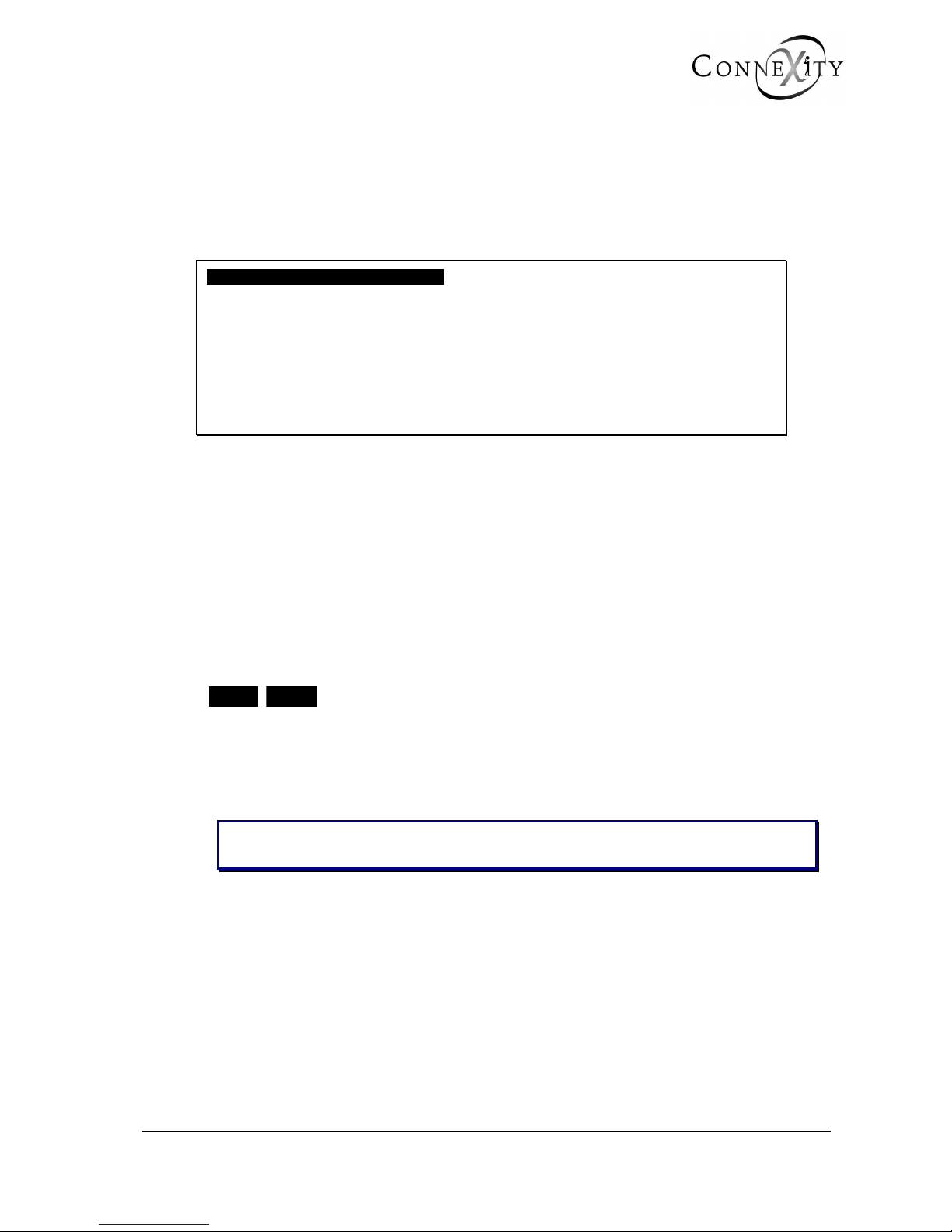
3. SYSTEM MANAGEMENT (MENU 3)
SYSTEM MANAGEMENT
1 DATE AND TIME MANAGEMENT
2 CARD MANAGEMENT
3 CONFIGURATION AND RECORDING
4 TERMINAL MANAGEMENT
5 MANAGEMENT PASSWORD
6 PARAMETER MANAGEMENT
7 MULTI-SITE MANAGEMENT
8 SOFTWARE LOCK MANAGEMENT
9 INTEGR. BUFFER MANAGEMENT
ENTER YOUR CHOICE .
----------------------------------------------
Figure 1: Menu 3 (System management - F1)
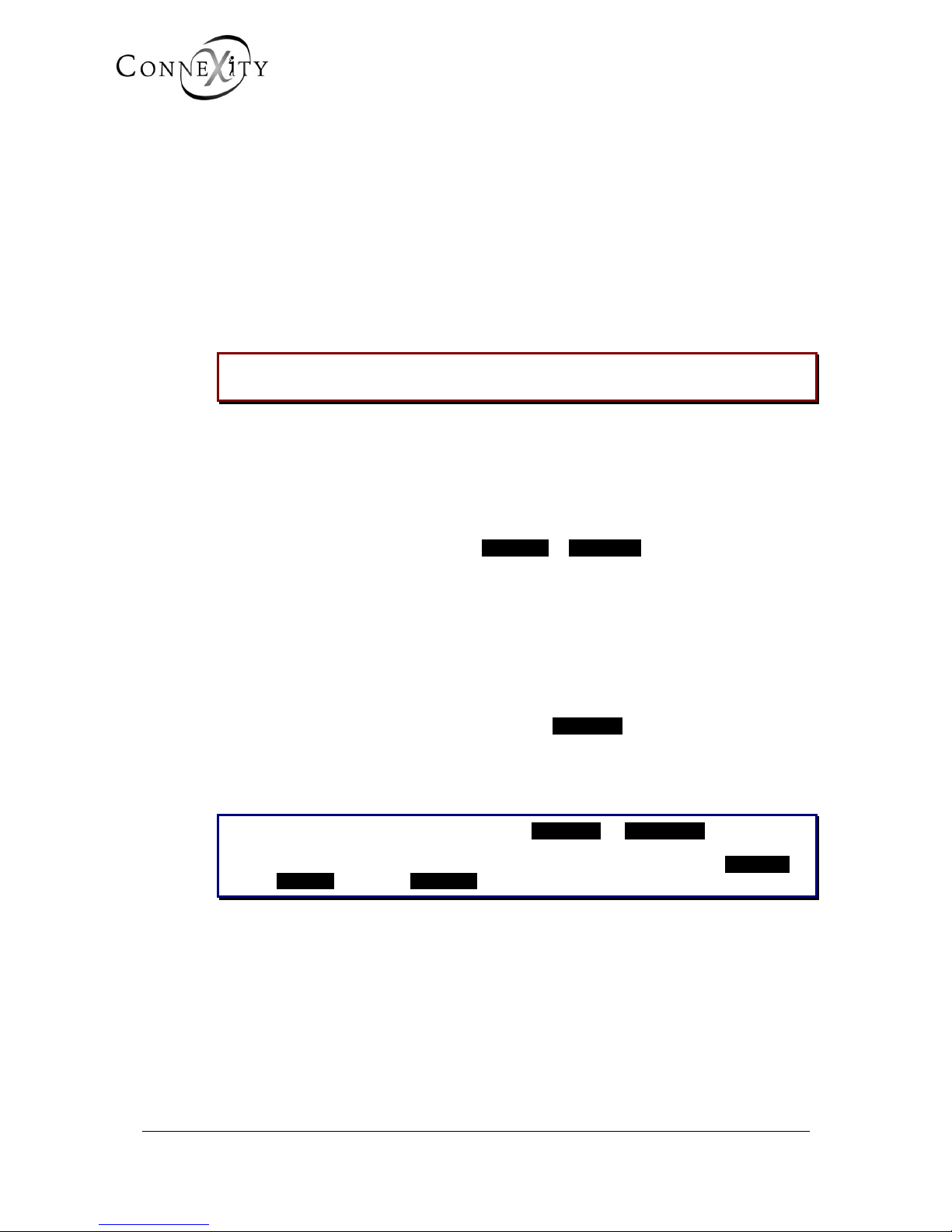
SYSTEM MANAGEMENT
1 DATE AND TIME MANAGEMENT
2 CARD MANAGEMENT
3.SVF-BVF CONFIGURATION
4 TERMINAL MANAGEMENT
5 PASSWORD MANAGEMENT
6 PARAMETER MANAGEMENT
7 MULTI-SITE MANAGEMENT
8 SOFTWARE LOCK MANAGEMENT
9 INTEGRAT. BUFFER MANAGEMENT
ENTER YOUR CHOICE .
----------------------------------------
Figure 2: Menu 3 (System management - F6)
For the Call Manager (F5): Menu 3 (System management) levels 3 (Configuration
and recording),
4 (Terminal management), and
9 (Integr. buffer management) are not available.
.
PS8149KENAA01 15/09/2004 Page 19
Ce document est la propriété de EADS et ne doit pas être reproduit ou communiqué sans autorisation.
This document is the property of EADS and may not be copied or circulated without authorisation.
3.1 DATE AND TIME MANAGEMENT (MENU 3-1)
For the Call Manager (F5): Menu 3-1 (Date and time management).
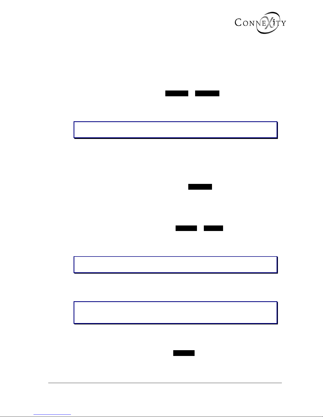
3.1.1 DATE AND TIME DEFINITION
MANAGEMENT OF DATE AND TIME
PRESENT TIME AND DATE
- TIME (format hh mm ss) 15 51 46
- DATE (format dd mm yyyy) 30 06 2003
NEXT PROGRAMMED TIME CHANGE NO
------------------------------------------------------
Figure 3: Time and date management
TIME (FORMAT HH MM SS)
Enter the hour (hh), minutes (mm) and seconds (ss) using 2 digits for each value.
DATE (FORMAT DD MM YYYY)
Enter the day (dd) and month (mm), using 2 digits for each value, and the year (yyyy),
using 4 digits.
NEXT PROGRAMMED TIME CHANGE
NO YES
This menu is used to switch to day light-saving time or to local standard time on the
requested date: this avoids having to carry out these changes on the customer site on the
day in question.
When you select this option, 3 other fields are displayed (see the section below).
Note: In this release, the customer can make the change himself using the interactive
menu on an attendant console or a digital set declared as a maintenance set.

.
Page 20 15/09/2004 PS8149KENAA01
Ce document est la propriété de EADS et ne doit pas être reproduit ou communiqué sans autorisation.
This document is the property of EADS and may not be copied or circulated without authorisation.
3.1.2 PROGRAMMING A CHANGE OF TIME
MANAGEMENT OF DATE AND TIME
PRESENT TIME AND DATE
- TIME (format hh mm ss) 15 53 14
- DATE (format dd mm yyyy) 30 06 2003
NEXT PROGRAMMED TIME CHANGE YES
- on (date format dd mm) .....
- At (time format hh mm) .....
- IT WILL BE (time format hh mm) .....
------------------------------------------------------
Figure 4: Date and time management (continued)
ON (DATE FORMAT DD MM)
Enter the date of the change: the day (dd) and month (mm), using 2 digits for each value.
AT (TIME FORMAT HH MM)
Enter the time of the change: the hour (hh) and minutes (mm), using 2 digits for each
value.
IT WILL BE (TIME FORMAT HH MM)
Enter the desired time for the change: the hour (hh) and minutes (mm), using 2 digits for
each value.
Note: The date and time can be updated on an attendant console or on a 520 or 640
digital set declared as a maintenance set in its extension characteristics. In
menu 1-7-2 (Miscellaneous Parameters), select YES for date and time
management.
Programming on telephone sets is as follows:
FUNCT. → SERVER → MORE → SYSTEM MANAGEMENT → ACCESS →
DATE and TIME.
The date and time are updated on the sets after any operation (Example: off-
hook/on-hook), after passing 8 p.m. or midnight, by unplugging or plugging in the
sets following an automatic reset.

.
PS8149KENAA01 15/09/2004 Page 21
Ce document est la propriété de EADS et ne doit pas être reproduit ou communiqué sans autorisation.
This document is the property of EADS and may not be copied or circulated without authorisation.
3.2 CARD MANAGEMENT (MENU 3-2)
For the Call Manager (F5): Menu 3-2 (Card management).
3.2.1 CARD TYPE AND STATUS
Depending on the system installed (M6501L/R IP PBX, XL, XS, XC M6504/M6540 IP
PBX), a screen which displays the various cards installed on the PBX appears: the card
type and status are displayed.
Note: Menu 3-2 (Card management) proposes 4 sub-menus for the X range. To declare
a card in an XL/XS/XC, select menu 3-2-1 (see section 3-2-5) .
TYPE
This field indicates the type of card in the specified location when the PBX is powered on
or on TOTAL RESET.
STATUS
This field indicates the card status:
IN SERVICE: Card being used in the PBX.
DISABLED: Card disabled because of a change being made.
NOT EQUIP.: Card absent from the system or used by an MMC to replace one
card with another of a different type (for example, replacing an
analogue card with a digital card).
FAULTY: Card previously in service and has been removed from the system.
NET ALARM: LSB status for NETWORK cards (in particular PTx/PVI) which
indicates network disconnection (IP, ISDN, etc.).
.
Page 22 15/09/2004 PS8149KENAA01
Ce document est la propriété de EADS et ne doit pas être reproduit ou communiqué sans autorisation.
This document is the property of EADS and may not be copied or circulated without authorisation.
3.2.2 PROCEDURE FOR INSTALLING A CARD
Warning:
♦ Before disabling a card, all the equipment interfaces on that card must first be
disabled.
♦ A card which supports an attendant console, a night console trunk group
declared in a trunk group cannot be changed to the status NOT EQUIP. This
equipment must be deleted beforehand.
♦ If no network link is connected to the PTx card, no TCP gateway link can be
enabled.
IMPORTANT: Always switch off your device before installing or uninstalling a card,
unless it is an LA16X or LN16X card in an XL cabinet (F6).
3.2.2.1 F1/F2
1. Set all the equipment interfaces on the card out of service (DISABLED).
2. Delete all the directory numbers assigned to the equipment interfaces on the card in
menu 1-1-1 (Extension characteristics).
3. Change the status of the carte from In service to Not equip.
4. Power off the PBX (Switch on the face plate of the power supply module) in the main
cabinet or the expansion cabinet.
5. Remove the card from the PBX.
6. Insert the new card.
7. Power on the PBX (Switch on the face plate of the power supply module) in the main
cabinet or the expansion cabinet.
8. Select the card type and validate the status In service (wait until the download is
complete).
9. If you are installing a subscriber card, redefine the directory numbers in menu 1-1-1
(Extensions characteristics).
Note: Changing the status of the card from In service to Not equip. destroys all the
links previously created. For a PT2 card to keep the links created when changing
from x channels to y channels, change the status of the card from In service to
Disabled (instead of Not equip.).
.
PS8149KENAA01 15/09/2004 Page 23
Ce document est la propriété de EADS et ne doit pas être reproduit ou communiqué sans autorisation.
This document is the property of EADS and may not be copied or circulated without authorisation.
3.2.2.2 F6
Replacing an "old generation" card with an "old generation" card:
1. Set all the equipment interfaces on the card out of service (DISABLED).
2. Delete all the directory numbers assigned to the equipment interfaces on the card in
menu 1-1-1 (Extension characteristics).
3. Change the status of the carte from In service to Not equip.
4. Power off the PBX (the main cabinet and the expansion cabinet(s)).
5. If it is an XS, open the cabinet.
Note: For further information on installing and replacing a card in an XL, XS or XC
cabinet, refer to “X-range Installation and Maintenance Guide”.
6. Remove the card from the PBX.
7. Insert the new card.
8. If it is an XS, close the cabinet.
9. Power on the PBX again (the main cabinet and the expansion cabinet(s).
10. Select the card type and validate the status In service (wait until the download is
complete).
11. If you are installing a subscriber card, redefine the directory numbers in menu 1-1-1
(Extensions characteristics).
Replacing an "old generation" card with a "new generation" card (LA16X, LN16X):
1. Change the (LA8, LN8) card status from In service to Disabled.
2. Power off the PBX (the main cabinet and the expansion cabinet(s)).
3. If it is an XS, open the cabinet.
Note: For further information on installing and replacing a card in an XL, XS or XC
cabinet, refer to “X-range Installation and Maintenance Guide”.
4. Remove the card from the PBX.
5. Insert the new card.
Note: In an XL cabinet, you can hot plug or unplug an LA16X or LN16X card. For further
information on an XL, XS or XC cabinet, refer to “X-range Installation and
Maintenance Guide”.
6. If it is an XS, close the cabinet.
7. Power on the PBX again (the main cabinet and the expansion cabinet).
8. Select card type and confirm the status In service.
9. Define all the directory numbers for the additional equipment interfaces on the card in
menu 1-1-1 (Extension characteristics).
.
Page 24 15/09/2004 PS8149KENAA01
Ce document est la propriété de EADS et ne doit pas être reproduit ou communiqué sans autorisation.
This document is the property of EADS and may not be copied or circulated without authorisation.
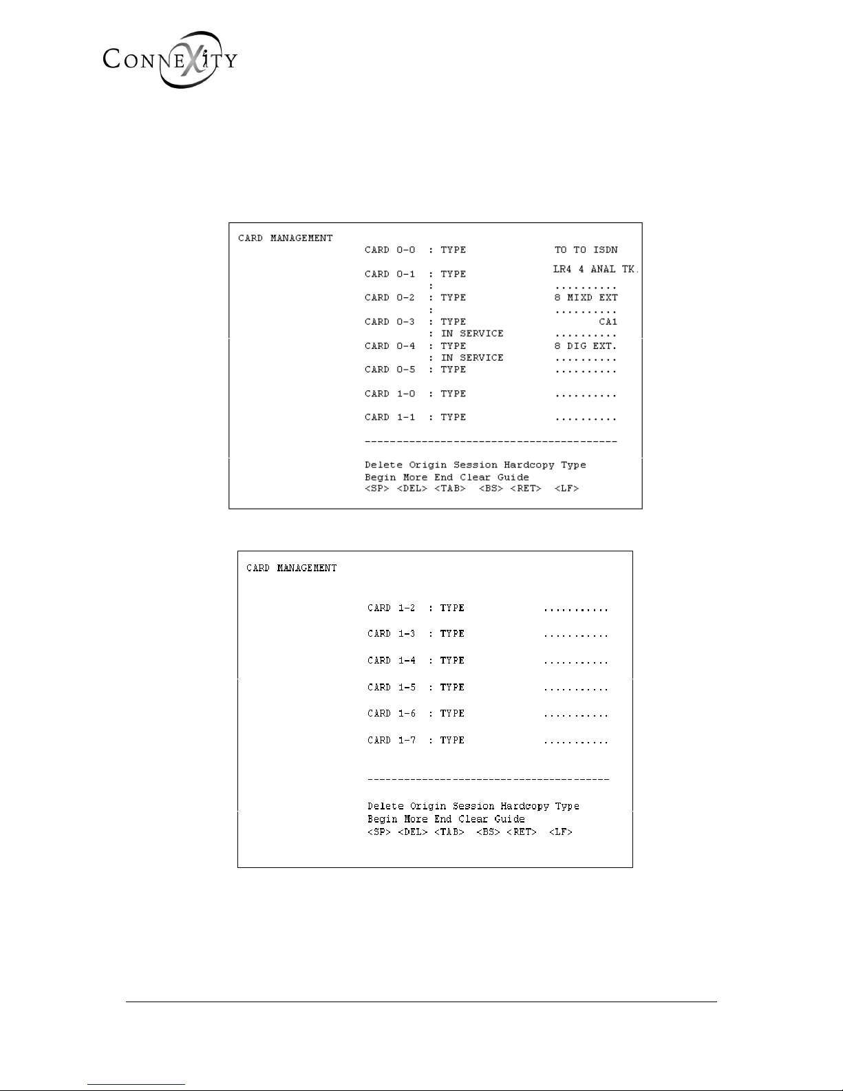
3.2.3 M6501L/R IP PBX CARDS
The M6501L has two cabinets: the main cabinet (0) and the expansion cabinet (1).
The slot number is therefore preceded by the cabinet number.
Example: Card 0-2 (second card of type 8 MIXD EXT. in cabinet 0)
Figure 5: Card management (M6501L/R)
Figure 6: Card management (M6501L/R) (continued)
When the system is powered on, the cards which do not have a processor, and which are
installed in the PBX, are identified and displayed automatically. The cards which have a
processor, such as CA1, LS1, CP1, CS1, are signalled as being in download status.
Slot 0-7 is used for the digital extensions of the OCT4 card.

.
PS8149KENAA01 15/09/2004 Page 25
Ce document est la propriété de EADS et ne doit pas être reproduit ou communiqué sans autorisation.
This document is the property of EADS and may not be copied or circulated without authorisation.
Slots 2-0 to 3-7 are used on the M6501L IP PBX (double cabinet).
If the equipment interface has LD4 or LT2 cards, these must be put in service using this
menu. The LT2 card is fitted for T2 or S2 (PRI).
The LS2 or LT2 card can only be installed in slot 04 or 05 (and 00 and 01 for 4 T2). You
can therefore use the LS2 card in two ways:
♦ ISDN:T2 Signalling - (telephone mode)
♦ QSIG signalling - (multi-site links)
Example:
You can use an LS2 card for ISDN:T2 in slot 5 and another LS2 card for QSIG
signalling in slot 04.
CAUTION: An LT2 or LS2 card placed in eq1 requires a TMOCT4 card.
CARD (CABINET NUMBER – SLOT NUMBER): TYPE
• • • • • • • • Use the terminal space bar to select a card type.
4 AB. ANAL. LA4 card for 4 analogue extensions.
4 AB. BOTHWAY LM4 card for 4 mixed extensions.
4 AB. COMMON LN4 card for 4 digital extensions.
8 AB. ANAL. LA8 card for 8 analogue extensions.
8 AB. BOTHWAY LM8 card for 8 mixed extensions.
8 AB. COMMON LN8 card for 8 digital extensions.
2 ANAL TK LR1 card with 2 analogue trunk line equipment interfaces.
4 ANAL TK LR4 card with 4 analogue trunk line equipment interfaces.
ISDN 2S0 LS1 card, 2 S0 equipment interfaces configuration.
ISDN T0-S0 LS1 card, 1 T0 + 1 S0 equipment interface configuration.
ISDN 2T0 LS1 card, 2 T0 equipment interfaces configuration.
LD4 T0/S0 card for 2- or 4-channel radio base stations.
TIE LINE IA1/LI1 card for 2- or 4-wire tie-line equipment interfaces.
CA1 Card for 4 V24 asynchronous links.
CS1 Card for 2 X25 asynchronous links.
CP1 Packet circuit coupler card with two equipment interfaces.
LB4 Card with 4 CT2 radio base station equipment interfaces.
LS2 LS2 card with ISDN T2 (PRI) and QSIG signalling.
LT2 Card fitted for S2, T2 (PRI), PCM or reduced.
CC1 Card with synchronous announcements.
BVF Card with IVB and synchronous announcements.
PTx
PTx card which manages links (maximum 16) and carries out
gateway functions (TCP/IP-X25) and tunnelling (X25 over IP).
CAUTION: No PTx card can be enabled unless the network cable is
connected.
.
Page 26 15/09/2004 PS8149KENAA01
Ce document est la propriété de EADS et ne doit pas être reproduit ou communiqué sans autorisation.
This document is the property of EADS and may not be copied or circulated without authorisation.
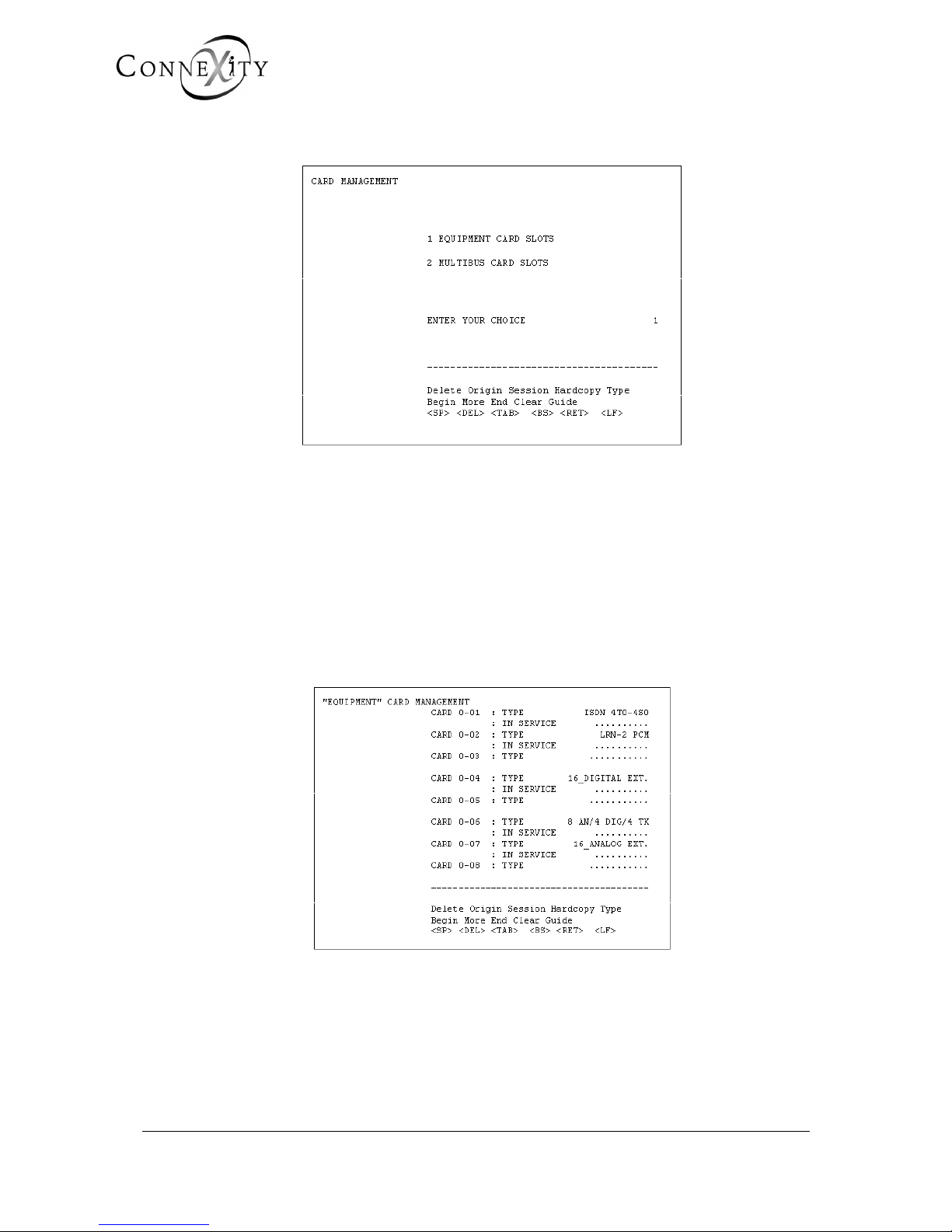
3.2.4 M6504/M6540 CARDS
Figure 7: Card management (M6504/M6540)
3.2.4.1 EQUIPMENT CARD SLOTS
The M6504/M6540 has two cabinets: the main cabinet (0) and the expansion cabinet (1).
The slot number is therefore preceded by the cabinet number.
Example: Card 0-2 (second card of type PCM LRN-2 in cabinet 0).
CABINET 0
Main cabinet with an FP04PD back plane (
TELEPHONE + DATA).
Figure 8: "Equipment" card management (M6504/M6540)
.
PS8149KENAA01 15/09/2004 Page 27
Ce document est la propriété de EADS et ne doit pas être reproduit ou communiqué sans autorisation.
This document is the property of EADS and may not be copied or circulated without authorisation.
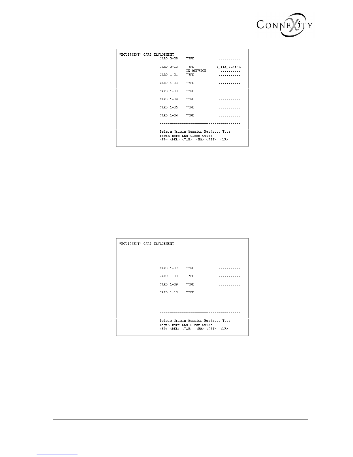
Figure 9: "Equipment" card management (M6504/M6540) (continued)
CABINET 1
Expansion cabinet with an FP04MD (TELEPHONE + DATA) or a FP04ER back plan
(TELEPHONE only).
For card management in the system, the main cabinet back plane (FP04MD) is divided in
two:
♦ EQUIPMENT side for the EQT card type. (example: LRN or LAE type cards),
♦ MULTIBUS side for CLX card type (example: ADP (T2) or ADB (T0/S0) type
cards.
Figure 10: "Equipment" card management (M6504/M6540) (continued)

.
Page 28 15/09/2004 PS8149KENAA01
Ce document est la propriété de EADS et ne doit pas être reproduit ou communiqué sans autorisation.
This document is the property of EADS and may not be copied or circulated without authorisation.
CARD TYPE ON TELEPHONE BUS SIDE
CARD X-XX: TYPE
• • • • • • • • Use the terminal space bar to select a card type.
LRN – 1 PCM LRN card with 2 PCM (64 TSs), in 1 PCM (PCM0) configuration.
LRN – 2 PCM LRN card with 2 PCM (64 TSs), in 2 PCM (PCM0-PCM1) configuration.
16 AB. ANAL. LAB card FOR 16 Z interface analogueue extensions.
16 AB. COMMON LAI card for 16 I interface digital extensions.
16 AB. NUM + DATA LAN.D card with 16 digital extensions (telephone + data).
32 AB. ANAL. LAE card for 32 Z interface analogue extensions.
32 AB. COMMON LAJ card for 32 I interface digital extensions.
ISDN 8T0 LAS card, 8 T0 equipment interfaces configuration.
ISDN 6T0 - 2S0 LAS card, 6 T0 + 2 S0 equipment interfaces configuration.
ISDN 4T0 - 4S0 LAS card, 4 T0 +4 S0 equipment interfaces configuration.
ISDN 2T0 - 6S0
LAS card, 2 T0 +6 S0 equipment interfaces configuration.
ISDN 8S0 LAS card, 8 S0 equipment interfaces configuration.
8 AN / 4 DIG / 4 TK
LAR card with 8 analogue extensions + 4 digital extensions + 4 analogue
trunk line equipment interfaces.
8 ANAL. TK.LRA/LRD LRD or LRA card with 8 analogue trunk line equipment interfaces.
8 ANAL.TK.LRB LRB or LRA card with 8 analogue trunk line equipment interfaces.
4 TIE LINE-A LIA card with four 2-wire tie-line equipment interfaces.
4 TIE LINE-B
LIB card with four 2- or 4-wire tie-line equipment interfaces, and voice
frequency signalling.
4 TIE LINE-C
LIC card with four 2- or 4-wire tie-line equipment interfaces, and E&M
signalling.
4 TIE LINE-D LID card, specific AVS 2000 application.
8 TIE LINE-E
LIE card with eight 2- or 4-wire tie-line equipment interfaces, and E&M
signalling.
16 RADIO BASES LAC card, used to connect 16 CT2 wireless base stations.
CONFER 1 PCM
CCB card Used to connect digital sets for the multi-conference
application.
CONFER 2 PCM
CCB card where one PCM used to connect a digital tape recorder and
a second PCM is used to connect digital sets for multi-conference
application.
CCA 16
ANNOUNCEMENT
CCA card with spoken announcements and conference circuits.
CCS 1 PCM
CCS card with synchronised messages, in 1 PCM configuration.
CCS 2 PCM
CCS card with synchronised messages, in 2 PCM configuration.
Note: The LRN 1 or 2 PCM field only appears for card slots 01 and 02 in the main cabinet.

.
PS8149KENAA01 15/09/2004 Page 29
Ce document est la propriété de EADS et ne doit pas être reproduit ou communiqué sans autorisation.
This document is the property of EADS and may not be copied or circulated without authorisation.
Reminder: The LAS card is used to connect 8 BRIs (type T0 or S0) to ISDN terminals
(8 interfaces, each with 2 B channels (64 kb/s) + 1 D channel (16 kb/s).
For LAS card operation, an IFS link must be declared (+ LAS - CLF wire
plugged in): see "Configuring "IFS" links".
CABINET 2
Cabinet with an FP04E back plane (
TELEPHONE).
CARD TYPE ON TELEPHONE BUS SIDE
CARDS 01 TO 16: TYPE
• • • • • • • • • Use the terminal space bar to select a card type.
16 ANALOG EXT. LAB card with 16 Z interface analogue extensions.
16 DIGITAL EXT. LAI card with 16 I interface digital extensions.
DIGITAL EXT.+TDD LAN.D card with 16 I interface + data digital extensions.
ISDN 8S0 LAS card, 8 S0 equipment interfaces configuration.
8 ANAL. TK.LRA/LRD LRD or LRA card with 8 analogue trunk line equipment interfaces.
4 TIE LINE–A
LIA card with 4 tie-line equipment interfaces and 50 Hz type or E&M
signalling.
4 TIE LINE-B
LIB card with four 2- or 4-wire tie-line equipment interfaces and
voice frequency signalling.
4 TIE LINE-C
LIC card with four 2- or 4-wire tie-line equipment interfaces and
E&M signalling.
8 TIE LINE-E
LIE card with eight 2- or 4-wire tie-line equipment interfaces and
50 Hz, E&M or 2E&2M signalling.
8 AN / 4 DIG / 4 TK
LAR card with 8 Z interface analogue extensions, 4 I interface
digital extensions, and 4 analogue trunk line equipment interfaces.
Note: The telephone expansion cabinet 2 supports LAS 8S cards only.
EQT positions 13 and 14 support LRD and LIX cards only.
Reminder: The LAS card is used to connect 8 T0 BRIs to the ISDN (NUMERIS) or
type S0 to ISDN terminals. 8 circuits each having 2 B channels (64 kbit/s)
+ 1 D channel (16 kbit/s).

.
Page 30 15/09/2004 PS8149KENAA01
Ce document est la propriété de EADS et ne doit pas être reproduit ou communiqué sans autorisation.
This document is the property of EADS and may not be copied or circulated without authorisation.
3.2.4.2 "MULTIBUS" SLOTS
The M6504/M6540 has two cabinets: the main cabinet (0) and the expansion cabinet (1).
The slot number is therefore preceded by the cabinet number.
Example: Card 0-2 (second card of type CCP in cabinet 0).
CABINET 0
Main cabinet with an FP04P back plane (
TELEPHONE).
Figure 11: "Multibus" card management (M6504/6540)
CABINET 1
Expansion cabinet with an FP04PD mixed back plane (TELEPHONE + DATA).
Figure 12: "Multibus" card management (M6504/6540) (continued)

.
PS8149KENAA01 15/09/2004 Page 31
Ce document est la propriété de EADS et ne doit pas être reproduit ou communiqué sans autorisation.
This document is the property of EADS and may not be copied or circulated without authorisation.
CARD TYPE ON MULTIBUS SIDE
CARDS 0-C1 TO 0-C4: TYPE
• • • • • • • • • Use the terminal space bar to select the CLx card type.
ISDN ADP T2
A
DP card, in T2 configuration with 30 equipment interfaces, each with
its own 64 kb/s B channel + (64 kb/s D channel).
ISDN ADP S2
A
DP card, in S2 configuration with 1 equipment interfaces to which the
thirty 64 kb/s channels + (64 kb/s D channel) are allocated.
ISDN ADQ T2
ADQ card with T2 interface for the public network.
ISDN ADQ S2 ADQ card with S2 interface for a terminal in the system.
ADQ1 T1
ADQ card with 1 T1 interface for the public network.
ADQ2 T1
ADQ card with 2 T1 interface for the public network.
ADQ1 PRI
ADQ card with PRI (Primary Rate Interface).
ADB 4T0-1S0 ADB card, 4 T0 + 1 S0 equipment interfaces configuration.
ADB 4T0-2S0 ADB card, 4 T0 + 2 S0 equipment interfaces configuration.
ADB 5T0 ADB card, 5 T0 equipment interfaces configuration.
ADB 5T0-1S0 ADB card, 5 T0 + 1 S0 equipment interfaces configuration.
ADB 6T0 ADB card, 6 T0 equipment interfaces configuration.
8ACCES LDS
LDSB card with 8 T0/S0 interfaces and 2/4 channel DECT base
stations.
16ACCES LDS
LDSA card with 16 T0/S0 interfaces and 2- or 4 channel DECT base
stations.
CLD CARD CLD card with 16 V24 asynchronous interfaces, V28 electrical mode.
CLM CARD
CLM card with 16 V24 asynchronous interfaces, V28 electrical mode,
(replaces the CLD card).
CLE CARD
CLE card with 4 asynchronous or synchronous line interfaces (HDLC,
X25, SNA type), V11 electrical mode.
CLF CARD
CLF card with 4 serial asynchronous or synchronous line interfaces
(HDLC, X25, SNA type), V10 electrical mode (compatible with V28).
CCP CARD
CCP card: packet circuit coupler with four 64 kb/s synchronous serial
interfaces.
LAT CARD
LAT card with 4 Z interface analogue extensions + 4 I interface digital
extensions + 4 asynchronous line interfaces (electrical mode) and 2 T0
equipment interfaces.
CRI CARD
CRI card which manages links (maximum 16), and carries out gateway
functions (TCP/IP-X25) and tunnelling (X25 over IP).
PVI
PVI card, 1 Ethernet/IP interface and voice over IP gateway (VOIP48/16/32 daughter cards).
CAUTION: No PVI card can be enabled unless the network cable is
connected.

.
Page 32 15/09/2004 PS8149KENAA01
Ce document est la propriété de EADS et ne doit pas être reproduit ou communiqué sans autorisation.
This document is the property of EADS and may not be copied or circulated without authorisation.
Note: The CLA card is a reduced version of the CLM card, with 4 asynchronous V24
interfaces (channels: 0, 1, 14, 15). It is downloaded using the CLM field
The CCP card can only be fitted in cabinet 0.
Reminder: The ADB card is used to connect 6 T0 BRIs to the ISDN (NUMERIS), of
which 2 interfaces can be converted to S0 for ISDN terminals. There are
six interfaces, each with two 64 kb/s B channels and one 16 kb/s D
channel. This card is put in service automatically.
SOFTWARE
SW. CLD
CARD
SW. CLE
CARD
SW. CLM
CARD
SW. CLF
CARD
This field indicates the software to be downloaded according to the CLx card type selected
on the Type field.
CAUTION: There is no compatibility check between the software requested and the
card to be downloaded.
THIS FIELD MUST BE USED WITH CARE.
STATUS
OUT OF SERVICE IN SERVICE NOT EQUIP. NET. ALARM
IN SERVICE
Status assigned automatically on Total Reset: this only applies to cards
identified as ANALOG, DIGITAL, DIGITAL + DATA, ANALOG TK.,
ISDN T0 (ADB card) and ISDN T2 (ADP card).
For the PCM LRN-1, PCM LRN- 2, TIE-LINE A, B, C, D, ISDN T0/S0
(LAS), T2/S2, or CLX cards, validate the status by pressing RETURN
or ENVOI.
OUT OF
SERVICE
This status is used to put a card temporarily out of service. The
equipment interfaces connected are also put OUT OF SERVICE.
NOT EQUIP.
This status is important because it is used to replace one card with
another of a different type (for example, replacing an analogue card
with a digital one, etc.).
NET. ALARM
LSB status for NETWORK cards (in particular PVI)
which indicates network disconnection (IP, ISDN,
etc.).
PUTTING THE LAS CARD IN SERVICE
IMPORTANT: Before putting the LAS card in service, you must first configure the
IFS link (see below).

.
PS8149KENAA01 15/09/2004 Page 33
Ce document est la propriété de EADS et ne doit pas être reproduit ou communiqué sans autorisation.
This document is the property of EADS and may not be copied or circulated without authorisation.
Proceed as follows to put in service an LAS card (ISDN T0/S0):
1. Select card type.
2. Check the connection of the cable (IFS link) between the LAS card and a junction
(00 to 03) on the CLF card.
3. Select the CLF card on the line: Card x-xx: Type
4. Set the CLF card In service and wait until the download is complete, then check
the LED VC Temps réel ("Real Time") on the CLF card.
5. Go to the menu DATA MANAGEMENT to define the characteristics of the IFS
link (LAS-CLF): see "Configuring "IFS" links".
3.2.4.3 CONFIGURING "IFS" LINKS
The IFS link must be configured before setting the LAS card in service (see the previous
section).
When you enter your password, display menu 2-1-1-1 (Link selection).
Figure 13: Link selection

.
Page 34 15/09/2004 PS8149KENAA01
Ce document est la propriété de EADS et ne doit pas être reproduit ou communiqué sans autorisation.
This document is the property of EADS and may not be copied or circulated without authorisation.
BY EQUIPMENT NUMBER
Enter a link name (CLF card) in this field, defined by the cabinet number (0 or 1), the card
slot in the cabinet (C1 to C4), and the junction number (00 to 03) on the CLF card. When
you validate this field, the following screen is displayed:
Figure 14: Link selection (continued)
LINK TYPE
In this field, select the link type IFS: The following screen is displayed:
Figure 15: Link selection (continued)
NAME
Enter the name of the link: 8 characters maximum (for example: LASIFS).
LAS LOCATION (CABINET CARD)
In this field, enter the location of the LAS card (cabinet number and card slot in cabinet):
the link is set service when the last parameter has been entered.
Go back to menu 3.2 (Card management) to put an ISDN T0/S0 type card in service.

.
PS8149KENAA01 15/09/2004 Page 35
Ce document est la propriété de EADS et ne doit pas être reproduit ou communiqué sans autorisation.
This document is the property of EADS and may not be copied or circulated without authorisation.
3.2.5 XL/XS/XC CARDS
CARD MANAGEMENT
1 COMMON BOARDS MANAGEMENT
2 - MOTHER BOARD MANAGEMENT - MIGRATION
3 IP BOARD PARAMETERS MANAGEMENT
4 ISDN BOARD SWITCHES STATUS
ENTER YOUR CHOICE .
----------------------------------------
Figure 16: Card management (XL, XS and XC)
Menu 3-2 (Card management) proposes the following 4 sub-menus for X range (XL, XS
and XC):
♦ Common boards management (Menu 3-2-1)
This menu is used to declare the cards in an XL/XS cabinet (card type and
status).
♦ Mother board management – Migration (Menu 3-2-2)
This menu is used to display device hardware and software configurations, and
change from one device to another.
♦ IP board parameters management (Menu 3-2-3)
This menu is used to modify the parameters for each PTx installed.
♦ ISDN board switches status (Menu 3-2-4)
This menu shows the jumper status for each ISDN access.

.
Page 36 15/09/2004 PS8149KENAA01
Ce document est la propriété de EADS et ne doit pas être reproduit ou communiqué sans autorisation.
This document is the property of EADS and may not be copied or circulated without authorisation.
3.2.5.1 COMMON BOARDS MANAGEMENT (MENU 3-2-1)
♦ XL
XL consists of one main cabinet and, if necessary, one or two expansion cabinets.
The equipment number is, therefore, preceded by the number of the cabinet in which it is
located:
♦ 1 = main cabinet
♦ 2 = 1
st
expansion cabinet
♦ 3 = 2
nd
expansion cabinet
Example: Card 1-03 (card in slot 03 of the main cabinet)
each cabinet contains 14 slots numbered from 00 to 13, corresponding to the following
physical positions:
UCT-L (RUCT-L)
01 00
03 02
05 04
07 06
09 08
11 10
13 12
COMMON BOARDS MANAGEMENT
CARD 1-00 : TYPE LT2 ISDN T2
: FAULTY ..........
CARD 1-01 : TYPE 32-CHANNEL PTx
: IN SERVICE ..........
CARD 1-02 : TYPE ...........
CARD 1-03 : TYPE 08-CHANNEL PTx
: NOT EQUIPPED ..........
CARD 1-04 : TYPE ...........
CARTD 1-05 : TYPE ...........
CARD 1-06 : TYPE LN16X 16 DS.SUB.
: IN SERVICE ..........
CARD 1-07 : TYPE LA16X 16 ANAL.SUB
: IN SERVICE ..........
----------------------------------------
Figure 17: Common boards management (XL)

.
PS8149KENAA01 15/09/2004 Page 37
Ce document est la propriété de EADS et ne doit pas être reproduit ou communiqué sans autorisation.
This document is the property of EADS and may not be copied or circulated without authorisation.
COMMON BOARDS MANAGEMENT
CARD 1-08 : TYPE ...........
CARD 1-09 : TYPE ...........
CARD 1-10 : TYPE ...........
CARD 1-11 : TYPE ...........
CARD 1-12 : TYPE ...........
CARD 1-13 : TYPE ...........
----------------------------------------
Figure 18: Common boards management (XL) (continued)
COMMON BOARDS MANAGEMENT
CARD 2-00 : TYPE ...........
CARD 2-01 : TYPE ...........
CARD 2-02 : TYPE ...........
CARD 2-03 : TYPE ...........
CARD 2-04 : TYPE ...........
CARTD 2-05 : TYPE ...........
CARD 2-06 : TYPE ...........
CARD 2-07 : TYPE ...........
----------------------------------------
Figure 19: Common boards management (XL) (continued)

.
Page 38 15/09/2004 PS8149KENAA01
Ce document est la propriété de EADS et ne doit pas être reproduit ou communiqué sans autorisation.
This document is the property of EADS and may not be copied or circulated without authorisation.
COMMON BOARDS MANAGEMENT
CARD 2-08 : TYPE ...........
CARD 2-09 : TYPE ...........
CARD 2-10 : TYPE ...........
CARD 2-11 : TYPE ...........
CARD 2-12 : TYPE ...........
CARD 2-13 : TYPE ...........
----------------------------------------
Figure 20: Common boards management (XL) (continued)
COMMON BOARDS MANAGEMENT
CARD 3-00 : TYPE ...........
CARD 3-01 : TYPE ...........
CARD 3-02 : TYPE ...........
CARD 3-03 : TYPE ...........
CARD 3-04 : TYPE ...........
CARTD 3-05 : TYPE ...........
CARD 3-06 : TYPE ...........
CARD 3-07 : TYPE ...........
----------------------------------------
Figure 21: Common boards management (XL) (continued)

.
PS8149KENAA01 15/09/2004 Page 39
Ce document est la propriété de EADS et ne doit pas être reproduit ou communiqué sans autorisation.
This document is the property of EADS and may not be copied or circulated without authorisation.
COMMON BOARDS MANAGEMENT
CARD 3-08 : TYPE ...........
CARD 3-09 : TYPE ...........
CARD 3-10 : TYPE ...........
CARD 3-11 : TYPE ...........
CARD 3-12 : TYPE ...........
CARD 3-13 : TYPE ...........
----------------------------------------
Figure 22: Common boards management (XL) (continued)
When the system is powered on, the cards which do not have a processor, and which are
installed in the PBX, are identified and displayed automatically. The cards which have a
processor, such as CA1, LS1, CP1, CS1, are signalled as being in download status.

.
Page 40 15/09/2004 PS8149KENAA01
Ce document est la propriété de EADS et ne doit pas être reproduit ou communiqué sans autorisation.
This document is the property of EADS and may not be copied or circulated without authorisation.
♦ XS
XS consists of one main cabinet and possibly one expansion cabinet.
The equipment number is, therefore, preceded by the number of the cabinet in which it is
located:
♦ 1 = main cabinet
♦ 2 = expansion cabinet
Example: Card 1-01 (card in slot 01 of the main cabinet)
Each cabinet contains 3 slots numbered from 00 to 02, corresponding to the following
physical positions:
02 01 00
UCT-S (RUCT-S)
COMMON BOARDS MANAGEMENT
CARD 1-00 : TYPE .........
CARD 1-01 : TYPE LN16X 16 DS.SUB
: IN SERVICE .........
CARD 1-02 : TYPE 32-CHANNEL PTX
: IN SERVICE .........
CARD 2-00 : TYPE .........
CARD 2-01 : TYPE .........
CARD 2-02 : TYPE .........
---------------------------------------------------
Figure 23: Card management (XS)

.
PS8149KENAA01 15/09/2004 Page 41
Ce document est la propriété de EADS et ne doit pas être reproduit ou communiqué sans autorisation.
This document is the property of EADS and may not be copied or circulated without authorisation.
♦ XC
XC consists of one main cabinet. It cannot be fitted with expansion cards, the subscriber
sockets and the T0/S0 interfaces are built into the CPU card.
Menu 3-2-1 "Common boards management" is, therefore, empty.
CARD (CABINET NUMBER – SLOT NUMBER): TYPE
• • • • • • • • Use the terminal space bar to select a card type.
LN8 8DG.EXT. LN8 card for 8 digital extensions.
LN16X 16DS.SUB. LN16 card for 16 digital extensions.
LM8 8MIXD. EXT. LM8 card for 4 digital extensions and 4 analogue extensions.
LA8 8ANAL.EXT. LA8 card for 8 analogue extensions.
LA16X 16ANAL.SUB LA16X card for 16 analogue extensions.
LR4 4ANAL.TK. LR4 card with 4 analogue trunk line equipment interfaces.
LR4A 4SUPPL.LR LR4 card with 4 analogue trunk line equipment interfaces.
TIE LINE LI1 card for 2- or 4-wire tie-line equipment interfaces.
CA1 Card for 4 V24 asynchronous links.
CS1 Card for 2 X25 asynchronous links.
CP1 Packet circuit coupler card with two equipment interfaces.
LT2 ISDN T2 (24tS) LT2 card in T2 configuration.
REDUCED LT2 LT2 card in reduced configuration (limited to 16TS).
S2 ISDN LT2 LT2 card in S2 configuration.
PRI ISDN LT2 (24 ts) LT2 card in PRI ISDN configuration
PCM LT2 (32it) LT2 card in PCM configuration
T1 PCM LT2 LT2 card in T1 PCM configuration
LD4 LD4 card for T0/S0 access, 2- or 4-channel radio base stations.
00 CHANNEL PTx
PTx card which performs gateway (TCP/IP-X25) and tunnelling (X25
tun. over IP) functions.
CAUTION: No PTx card can be enabled unless the network cable is
connected.
08 CHANNEL PTx
PTx card which performs gateway (TCP/IP-X25), tunnelling (X25
tun. over IP) and 8 voice over IP circuit management functions.
CAUTION: No PTx card can be enabled unless the network cable is
connected.

.
Page 42 15/09/2004 PS8149KENAA01
Ce document est la propriété de EADS et ne doit pas être reproduit ou communiqué sans autorisation.
This document is the property of EADS and may not be copied or circulated without authorisation.
16-CHANNEL PTx
16-channel PTx card which performs gateway (TCP/IP-X25),
tunnelling (X25 tun. over IP) and 16 voice over IP circuit
management functions.
CAUTION: No PTx card can be enabled unless the network cable is
connected.
32-CHANNEL PTx
32-channel PTx card which performs gateway (TCP/IP-X25),
tunnelling (X25 tun. over IP) and 32 voice over IP circuit
management functions.
CAUTION: No PTx card can be enabled unless the network cable is
connected.
3.2.5.2 MOTHER BOARD MANAGEMENT – MIGRATION (MENU 3-2-2)
This MMC is used to display device hardware and software configurations, and change
from one device to another. The hardware view corresponds to the actual platform and
cannot be modified. The software view corresponds to the database content and cannot be
modified. In general, the hardware and software configurations are identical. They may
vary in the following cases:
♦ if you add or remove an XS or XL expansion cabinet
♦ if you carry out a back-up / restore operation (for instance XS configuration back-
up and restore on an XL)
♦ if you change from one device to another.
♦ XL
MOTHER BOARD MANAGEMENT - MIGRATION
UCT: HARDWARE VIEW SOFTWARE VIEW
XL CONFIGURATION XL
PTX EN 0-04: IN SERVICE ..........
HSCX EN 0-05 : IN SERVICE ..........
BVF EN 0-06 : IN SERVICE ..........
CLASS SERVICE TYPE V23
TMS VC5409 TYPE 5409:SUBSC.+SUBSC.
STAT: IN SERVICE ..........
----------------------------------------
Figure 24: XL hardware and software configurations – Migration (menu 3-2-2)

.
PS8149KENAA01 15/09/2004 Page 43
Ce document est la propriété de EADS et ne doit pas être reproduit ou communiqué sans autorisation.
This document is the property of EADS and may not be copied or circulated without authorisation.
UCT: HARDWARE VIEW SOFTWARE VIEW
XL CONFIGURATION
Read-only field. Used to view the device
hardware configuration (one XL-cabinet, two
XXL-cabinet, three XXXL-cabinet
configuration).
XL XXL XXXL
Used to view the device software configuration
(one XL-cabinet, two XXL-cabinet, three
XXXL-cabinet configuration). You can modify
this field in order to change from one device to
another (add or remove one expansion
cabinet).
PTX EN 0-04: STATUS
HSCX EN 0-05: STATUS
MEVO EN 0-06: STATUS
Read-only field which indicates the position
and status of virtual cards (IN SERVICE,
DISABLED, FAULTY).
A virtual card has the same functions as
an expansion card but is installed on the
CPU card (HSCX = CP1).
IN SERVICE DISABLED ………...
IN SERVICE
Used to activate the virtual card in the PBX.
DISABLED
Used to deactivate the virtual card for
replacement.
.............
Used to maintain the virtual card status.
CLASS SERVICE TYPE
Note: This line is only displayed for a configuration using both set types.
V23 DTMF
CLASS service allows analogue terminals to receive the following information about the
current call: Caller number (if there is no call offering restriction) and date and time of call
(only available in V23 mode). Select V23 for standard European class sets and DTMF for
Danish class sets.
TMS VC5409: TYPE
5409 : EXTENSION 5409 : SUBSC. + SOCOTEL 5409 : SUBSC. + R2 ………..
Select the right TMS type.
STAT: IN SERVICE
Field which indicates the TMS status.
The following transitions are possible:
IN SERVICE NOT EQUIP. DISABLED ………..

.
Page 44 15/09/2004 PS8149KENAA01
Ce document est la propriété de EADS et ne doit pas être reproduit ou communiqué sans autorisation.
This document is the property of EADS and may not be copied or circulated without authorisation.
♦ XS
MOTHER BOARD MANAGEMENT - MIGRATION
UCT: hardware view software view
XXS CONFIGURATION XXS
DIG. EN 0-00: IN SERVICE .........
ANAL EN 0-01: IN SERVICE .........
S/T0 EN 0-02: IN SERVICE .........
T0 EN 0-03 : IN SERVICE .........
PTX EN 0-04: IN SERVICE .........
HSCX EN 0-05: IN SERVICE .........
BVF EN 0-06: IN SERVICE ..........
DIGITAL SET: 8 8
ANALOG SET: 8 8
ONLY T0 ACCESS : 2 2
CLASS SERVICE TYPE V23
TMS VC5402 TYPE 5402 : EXTENSION
STAT: IN SERVICE .........
---------------------------------------------------
Figure 25: XS hardware and software configurations – Migration (menu 3-2-2)

.
PS8149KENAA01 15/09/2004 Page 45
Ce document est la propriété de EADS et ne doit pas être reproduit ou communiqué sans autorisation.
This document is the property of EADS and may not be copied or circulated without authorisation.
UCT: HARDWARE VIEW SOFTWARE VIEW
XXS CONFIGURATION
Read-only field. Used to view the device
configuration (one XS-cabinet or two XXScabinet configuration)
XS XXS XL XXL XXXL GX-GLOBAL
Used to view the device software configuration
(one XS-cabinet or two XXS-cabinet
configuration). You can modify this field in order
to change from one device to another (add or
remove one expansion cabinet, change from an
XS cabinet to an XL cabinet).
GX-GLOBAL is a software view used for XS
=> XL migration and to display the position of
XS on the CPU card, as well as the common
positions of XL. It is thus possible to request
the transfer of the extensions located on the
XS CPU card to a new location on the XL.
Once the extensions are transferred, we
recommend that you realign the software
view and the hardware view.
NUM DIG. EN 0-00: STATUS
ANAL EN 0-01: STATUS
S/T0 EN 0-02: STATUS
T0 EN 0-03: STATUS
PTX EN 0-04: STATUS
HSCX EN 0-05: STATUS
BVF EN 0-06: STATUS
Read-only field which indicates the position
and status of virtual cards (IN SERVICE,
DISABLED, FAULTY).
A virtual card has the same functions
as an expansion card but is installed on
the CPU card (HSCX = CP1, S/T0 and
T0 = LD4).
IN SERVICE DISABLED ………...
IN SERVICE
Used to activate the virtual card in the PBX.
DISABLED
Used to deactivate the virtual card for
replacement.
………...
Used to maintain the virtual card status.
DIGITAL SETS: 8
Indicates the number of digital sets on the
CPU card.
8
Indicates the number of digital sets using the
software.

.
Page 46 15/09/2004 PS8149KENAA01
Ce document est la propriété de EADS et ne doit pas être reproduit ou communiqué sans autorisation.
This document is the property of EADS and may not be copied or circulated without authorisation.
UCT: HARDWARE VIEW SOFTWARE VIEW
ANALOGUE SETS: 8
Indicates the number of analogue sets on the
CPU card.
8
Indicates the number of analogue sets using
the software.
ACCES UNIQUEMENT T0 : 2
Indicates the number of T0 accesses on the
CPU card.
2
Indicates the number of T0 accesses using the
software.
CLASS SERVICE TYPE
Note: This line is only displayed for a configuration using both set types.
V23 DTMF
CLASS service allows analogue terminals to receive the following information about the
current call: Caller number (if there is no call offering restriction) and date and time of call
(only available in V23 mode). Select V23 for standard European class sets and DTMF for
Danish class sets.
TMS VC5402: TYPE
5402 : EXTENSION
………..
Select the right TMS type.
STAT: IN SERVICE
Field which indicates the TMS status.
The following transitions are possible:
IN SERVICE NOT EQUIP. DISABLED ………..

.
PS8149KENAA01 15/09/2004 Page 47
Ce document est la propriété de EADS et ne doit pas être reproduit ou communiqué sans autorisation.
This document is the property of EADS and may not be copied or circulated without authorisation.
♦ XC
MOTHER BOARD MANAGEMENT - MIGRATION
UCT: hardware view software view
XC CONFIGURATION XC
DIG. EN 0-00: IN SERVICE .........
ANAL EN 0-01: IN SERVICE .........
S/T0 EN 0-02: IN SERVICE .........
T0 EN 0-03: DISABLED .........
PTX EN 0-04: IN SERVICE .........
HSCX EN 0-05: IN SERVICE .........
BVF EN 0-06: IN SERVICE ..........
DIGITAL SET: 4 4
ANALOG SET: 4 4
ONLY T0 ACCESS : 0 0
CLASS SERVICE TYPE V23
TMS VC5402 TYPE 5402 : EXTENSION
STAT: IN SERVICE .........
---------------------------------------------------
Figure 26: XC hardware and software configurations – Migration (menu 3-2-2)
UCT: HARDWARE VIEW SOFTWARE VIEW
XC CONFIGURATION
Read-only field. Used to view the device
configuration (one XC-cabinet configuration).
XC XS XXS XL XXL XXXL GX-GLOBAL
Used to view the device software configuration (one
XC-cabinet configuration). You can modify this field in
order to change from one device to another (change
from an XC cabinet to an XS cabinet).
GX-GLOBAL is a software view used for XC =>
XS or XC => XL migration and to display the
position of XC on the CPU card, as well as the
common positions of XS or XL. It is thus possible
to request the transfer of the extensions located
on the XC CPU card to a new location on the XS
or XL. Once the extensions are transferred, we
recommend that you realign the software view
and the hardware view.

.
Page 48 15/09/2004 PS8149KENAA01
Ce document est la propriété de EADS et ne doit pas être reproduit ou communiqué sans autorisation.
This document is the property of EADS and may not be copied or circulated without authorisation.
NUM DIG. EN 0-00: STATUS
ANAL EN 0-01: STATUS
S/T0 EN 0-02: STATUS
T0 EN 0-03: STATUS
PTX EN 0-04: STATUS
HSCX EN 0-05: STATUS
BVF EN 0-06: STATUS
Read-only field which indicates the position
and status of virtual cards (IN SERVICE,
DISABLED, FAULTY).
A virtual card has the same functions as an
expansion card but is installed on the CPU
card (HSCX = CP1, S/T0 = LD4).
IN SERVICE DISABLED ………...
IN SERVICE
Used to activate the virtual card in the PBX.
DISABLED
Used to deactivate the virtual card for
replacement.
………...
Used to maintain the virtual card status.
DIGITAL SETS: 4
Indicates the number of digital sets on the
CPU card.
4
Indicates the number of digital sets using the
software.
ANALOGUE SETS: 4
Indicates the number of analogue sets on the
CPU card.
4
Indicates the number of analogue sets using
the software.
ONLY TO ACCESS T0 : 0
Indicates the number of T0 accesses on the
CPU card.
0
Indicates the number of T0 accesses using the
software.
CLASS SERVICE TYPE
Note: This line is only displayed for a configuration using both set types.
V23 DTMF
CLASS service allows analogue terminals to receive the following information about the
current call: Caller number (if there is no call offering restriction) and date and time of call
(only available in V23 mode). Select V23 for standard European class sets and DTMF for
Danish class sets.
TMS VC5402: TYPE
5402 : EXTENSION
………..
Select the right TMS type.
STAT: IN SERVICE
Field which indicates the TMS status.
The following transitions are possible:
IN SERVICE NOT EQUIP. DISABLED ………..

.
PS8149KENAA01 15/09/2004 Page 49
Ce document est la propriété de EADS et ne doit pas être reproduit ou communiqué sans autorisation.
This document is the property of EADS and may not be copied or circulated without authorisation.
3.2.5.3 IP BOARD PARAMETERS MANAGEMENT (MENU 3-2-3)
IP BOARD PARAMETERS MANAGEMENT
EQUI IP ADDRESS SUB-NETWORK ADD
--------------------------------------- 0-04 131.129.255.53 255.255.255.224
1-01 131.129.255.54 255.255.255.224
SELECT THE IP BOARD 004
----------------------------------------
Figure 27: IP board parameters management (menu 3-2-3)
This menu is used to view all the declared PTX cards (including the virtual card fitted on
the UCT card corresponding to position 0-04), the IP addresses and the associated subnetwork masks. The last line is used to select one of the cards in order to display and
modify its characteristics.
LOC
Indicates the card's position in the cabinet.
The equipment number is preceded by the number of the cabinet in which it is located:
♦ 0 : position on the CPU card (PTx virtual card in 0-04)
♦ 1 : position in the main cabinet (XL and XS)
♦ 2 : position in the expansion cabinet (XXL and XXS)
♦ 3 : position in the second expansion cabinet (XXXL)
Example: EQUIP 0-04 (position 04 in the CPU card)
EQUIP 2-03 (position 03 in the expansion cabinet)
IP ADDRESS
Card IP address over 4 bytes. This address is displayed as decimal values separated by
points.
Note: The integrated IP port on the UCT CPU card is declared automatically (pre-
defined IP address = 192.168.65.01 and sub-network mask = 255.255.255.0).
This function is used to manage the PBX (after a TOTAL Reset) internally via a
management tool (M7420 or M7425) connected to the Ethernet port of the UCT
CPU card using a twisted cable. You can then re-configure the UCT IP address.

.
Page 50 15/09/2004 PS8149KENAA01
Ce document est la propriété de EADS et ne doit pas être reproduit ou communiqué sans autorisation.
This document is the property of EADS and may not be copied or circulated without authorisation.
SUB-NETWORK ADD
The number of the sub-network and the number of the set on the sub-network.
The sub-network address and IP address must respect the following relations:
♦ if the first bit of the IP address is 0 (class A), the sub-network address must be in
the form: 255.xxx.xxx.xxx,
♦ if the first 2 bits of the IP address are 10 (class B), the sub-network address must
be in the form: 255.255.xxx.xxx,
♦ if the first 3 bits of the IP address are 110 (class C), the sub-network address must
be in the form: 255.255.255.xxx.
SELECT THE IP BOARD
Using the space bar, select in this drop-down menu the position of a card to display and
modify its characteristics. Press Enter to confirm.
Note: Position 0-04 indicates the IP address position on the CPU card.
IP BOARD PARAMETRES 0-04
IP ADDRESS 131.129.255.53.
MASK 255.255.255.224
DEFAULT ROUTER 131.129.255.33.
UDP PORT 40000
TCP PORTS: FIRST NUMBER 41000
LAST NUMBER 41999
ETHERNET ADDRESS 08-00-71-09-80-2D
LINK TYPE 10 Mb HALF DUPLEX
----------------------------------------
Figure 28: IP card selection
The title indicates the card's position (cabinet number and position of the card in the
cabinet).
IP ADDRESS
Card IP address on 4 bytes.
Example: 192.42.11.154
Example: 0.0.0.0, 255.255.255.255 and 127.0.0.1 are not valid addresses.
Note: The decimal value of the first byte must not be greater than 223; if it is, the MMC
displays the message: ‘ SYNTAX ERROR ’.

.
PS8149KENAA01 15/09/2004 Page 51
Ce document est la propriété de EADS et ne doit pas être reproduit ou communiqué sans autorisation.
This document is the property of EADS and may not be copied or circulated without authorisation.
PTX CARD SLOT :
The IP address mask which comprises the number of the sub-network and the number of
the set on the sub-network.
The mask and IP address must respect the following rules:
♦ if the first bit of the IP address is 0 (class A), the mask must be in the form:
255.xxx.xxx.xxx,
♦ if the first two bits of the IP address are 10 (class B), the mask must be in the form:
255.255.xxx.xxx,
♦ if the first three bits of the IP address are 110 (class C), the mask must be in the
form: 255.255.255.xxx.
DEFAULT ROUTER
Router address. Only the IP address is mandatory: non provided data are at 0.
UDP PORT
Port number (5 digits maximum): value between 2050 and 65000 (by default, the port is set
at 40000).
TCP PORTS
- FIRST NUMBER
Port number (5 digits maximum): value between 0 and 65534 (by default, the port is set at
41000).
- LAST NUMBER
Port number (5 digits maximum): value between 0 and 65534 (by default, the port is set at
41999).
The difference between the first and last number of the port must be at least equal to 500.
If this difference is not respected, the second number is automatically updated to restore
this difference.
ETHERNET ADDRESS
ETHERNET or MAC address of card over 6 bytes.
This address is displayed as hexadecimal values separated by dashes. Example: 08-0071-03-00-0F
If the card is not in service, the Ethernet address is replaced by: "................"
LINK TYPE
Indicates the type of IP link connected to a PTx card:
♦ ………. (no link present, card “not connected” or “disabled”)
♦ 10 Mb Half Duplex
♦ 10 Mb Full Duplex
♦ 100 Mb Half Duplex
♦ 100 Mb Full Duplex

.
Page 52 15/09/2004 PS8149KENAA01
Ce document est la propriété de EADS et ne doit pas être reproduit ou communiqué sans autorisation.
This document is the property of EADS and may not be copied or circulated without authorisation.
3.2.5.4 ISDN BOARD SWITCHES STATUS (MENU 3-2-4)
ISDN BOARD SWITCHES STATUS
EQT NO. TYPE DIR NUM. / FX AUTO-SUPPLY
-------------------------------------------------------
0-02-00 S0 300 YES
0-02-01 DECT FBORNE0 YES
0-02-02 T0 FT0-ETSI NO
0-02-03 T0 FT0-ETSI NO
----------------------------------------------------
Figure 29: ISDN board switches status (menu 3-2-4)
This menu indicates the jumper status for each ISDN access of the UCT-S (XS) and UCTC (XC) cards.
EQT NO.
Indicates the ISDN access equipment number (cabinet, card, equipment). The S/T0
subscribers on the CPU card (XS and XC) are used in positions 0-02-00 to 0-02-03.
TYPE
Indicates the ISDN subscriber type: T0 (trunk group), S0 (set), DECT (DECT base station).
DIR NUM. / FX
Indicates the associated trunk group (for network, DECT base station) or directory number
(for S0 set).
AUTO-SUPPLY
Indicates whether the access is auto-supplied.

.
PS8149KENAA01 15/09/2004 Page 53
Ce document est la propriété de EADS et ne doit pas être reproduit ou communiqué sans autorisation.
This document is the property of EADS and may not be copied or circulated without authorisation.
3.3 MENU (3-3)
For the Call Manager (F5): this menu is not available.
F2: Menu 3-3 (Hardware configuration management)
F1: Menu 3-3 (Configuration and recording)
CONFIGURATION AND MESSAGE
1 HARDWARE CONFIGURATION
2 BVF: RECORD ANNOUNCEMENTS
ENTER YOUR CHOICE .
Figure 30: Configuration and recording (Menu 3-3) (F1)
F6 (XL/XS/XC): Menu 3-3 (SVF-BVF configuration)
SVF-BVF CONFIGURATION
1 SVF-BVF: RECORD ANNOUNCEMENTS
2 SVF-BVF BOARD ACCESS CONFIGURATION
GENERAL CHARACTERISTICS OF IVS IVB
ENTER YOUR CHOICE .
----------------------------------------
Figure 31: SVF-BVF configuration (Menu 3-3) (F6)

.
Page 54 15/09/2004 PS8149KENAA01
Ce document est la propriété de EADS et ne doit pas être reproduit ou communiqué sans autorisation.
This document is the property of EADS and may not be copied or circulated without authorisation.
3.3.1 HARDWARE CONFIGURATION (M6501 L/R IP PBX AND M6504/M6540 IP
PBX) (MENU 3-3-1)
3.3.1.1 M6501L/R IP PBX
CONFIG. MANAGEMENT
CLASS SERVICE TYPE V23
TMS BASIC: : TYPE SUBSC.+SUBSC.
: STATUS IN SERVICE
TMS TOCT: : TYPE SUBSC.+SUBSC.
: STATUS IN SERVICE
--------------------------------------------
Figure 32: Hardware configuration (M6501L/R IP PBX)
CLASS SERVICE TYPE
Note: This line is only displayed for a configuration using both set types.
V23 DTMF
CLASS service allows analogue terminals to receive the following information about the
current call: Caller number (if there is no call offering restriction) and date and time of call
(only available in V23 mode). Analogue terminals using the Class service are special
terminals with a display.
V23 Selection for standard European Class sets
DTMF Selection for Danish Class sets
TMS BASIC:
TYPE
• • • • • •
EXTENSION NETWORK 1 NETWORK 2 For OCT4B
This field cannot be modified because the standard TMS is configured as
EXTENSION For OCT4

.
PS8149KENAA01 15/09/2004 Page 55
Ce document est la propriété de EADS et ne doit pas être reproduit ou communiqué sans autorisation.
This document is the property of EADS and may not be copied or circulated without authorisation.
STATUS
IN SERVICE OUT OF SERVICE NOT EQUIP.
This state is selected automatically on Total Reset. The system takes account of the TMS
and downloads them.
OUT OF SERVICE Put 1 TMS out of service.
IN SERVICE Used for downloading new TMS software.
TMS TOCT:
TYPE
• • • • • •
EXTENSION NETWORK 1 NETWORK 2 For OCT4
The TMS TOCT is an additional TMS for a TOCT daughter card TMOCT4 (OCT4).
For the configuration, select TMS TOCT: EXTENSION RAM or NETWORK 2.
3.3.1.2 M6504/M6540 IP PBX
Hardware description
The OCI is equipped by default with a TOCH2 card (HJ2723A), with 2 RAM TMSs and one
MOCI card. These 2 TMSs can be downloaded by programming either in EXTENSION
RAM code (DTMF transmitters and receivers) or in NETWORK RAM code (MF SOCOTEL
transmitters and receivers).
On system start up, the 2 TMs are automatically configured EXTENSION RAM. The TMS
configured as EXTENSION RAM can manage:
♦ 1 x 330 Hz tone generator (-8 dBmo)
♦ 2 x 440 Hz tone generators (-11 dBmo)
♦ 1 x 330/440 Hz tone generator
♦ 2 x 330/440 Hz tone detectors
♦ 2 x 4-party conferences
♦ 2 x DTMF transmitters
♦ 2 x DTMF receivers
The TMS configured as NETWORK RAM 2 can manage:
♦ 1 x 330 Hz tone generator (-8 dBmo)
♦ 1 x 440 Hz tone generator (-11 dBmo)
♦ 1 x 330/440 Hz tone detector
♦ 2 x 4-party conferences
♦ 2 MF SOCOTEL transmitters
♦ 2 MF SOCOTEL receivers
♦ 2 x R2 code receivers
♦ 2 x R2 code transmitters

.
Page 56 15/09/2004 PS8149KENAA01
Ce document est la propriété de EADS et ne doit pas être reproduit ou communiqué sans autorisation.
This document is the property of EADS and may not be copied or circulated without authorisation.
The TMS configured as NETWORK RAM can manage:
♦ 1 x 330 Hz tone generator (-8 dBmo)
♦ 1 x 440 Hz tone generator (-11 dBmo)
♦ 2 x 330/440 Hz tone detectors
♦ 2 x 4-party conferences
♦ 4 MF SOCOTEL transmitters
♦ 4 x MF SOCOTEL receivers
A second TOCH2 card can be fitted to the OCI card (optional).
Figure 33: Hardware configuration (M6504/M6540)
For each TMS TOCH1 (DSP2 and DSP3), TMS TOCH2 (DSP4 and DSP5), you must
select the DSP type and state.
TYPE
• • • • • • EXTENSION RAM NETWORK RAM
NETWORK RAM 2
For the DSP2, do not modify the default field EXTENSION RAM.
STATUS
IN SERVICE OUT OF SERVICE NOT EQUIP.
IN SERVICE Takes into account the TSMs and downloads them.
OUT OF SERVICE Put 1 TMS out of service.
NOT EQUIP. Used for downloading new TMS software.
LRN SYNC FOR 1
ST
PCM ONLY
NO YES
Set YES for a public operator PCM and a PRIVATE PCM.

.
PS8149KENAA01 15/09/2004 Page 57
Ce document est la propriété de EADS et ne doit pas être reproduit ou communiqué sans autorisation.
This document is the property of EADS and may not be copied or circulated without authorisation.
EXTENSION CABINET
ABSENT DATA + TEL. TELEPHONE
On system start up, this field is configured automatically according to the type of expansion
cabinet.
The composition of the data + telephone expansion cabinet is identical to that of the basic
cabinet.
The telephone expansion cabinet has 14 slots for telephone cards.
3.3.2 RECORD ANNOUNCEMENTS
F1: Menus 3-3-2 and 5-5-2-8 (BVF: Recording messages)
F6 (XL/XS/XC): Menus 3-3-1 and 5-5-2-5 (SVF-BVF: Recording messages)
RECORD ANNOUNCEMENTS
PHYSICAL SLOT OF SOURCE …
BOARD PHYSICAL EQUIPMENT …
CATALOGUE NUM/GUIDE …
- LABEL ……..
- DURATION IN SEC. …
RECORDING PARAMETERS
- CATALOGUE-MIXED GUIDE …
- RECORDING LEVEL …
- ATTENUATE MUSIC BY VOICE YES
start recording YES
Figure 34: Record announcements
This menu is used to record customised announcements using a digital or analogue set,
and to replace the pre-configured announcements on the card with new announcements.
Updating messages (also called announcements):
♦ requires the utility MCTOOLS Messages, on a CSS type card (F2)
♦ requires the utility MCTOOLS Messages, on a CC1 type card (F1)
♦ requires the utility M7420 Music Manager on a UTC card (F6).
For messages written in Flash PROM, a list showing the location and length of each
message is displayed. Synchronised messages are broadcast from the beginning. This
menu can therefore be used to listen to the different message on the card without having
to temporarily define a definable tone.
Note: Accessing this menu puts the set out of service: it is therefore not recommended
to access this menu unnecessarily.
PHYSICAL SLOT OF SOURCE
Enter the equipment number of the set from which the announcement will be recorded
(four digits for F1 and five digits for F6).

.
Page 58 15/09/2004 PS8149KENAA01
Ce document est la propriété de EADS et ne doit pas être reproduit ou communiqué sans autorisation.
This document is the property of EADS and may not be copied or circulated without authorisation.
BOARD PHYSICAL EQUIPMENT
Enter the equipment number of the card containing the pre-configured announcements (4
digits for F1 and 006 for F6).
Note: For F6, the voice mail system's virtual card on the UCT card contains pre-
configured annoncements. Its equipment number is 006.
CATALOGUE NUM/GUIDE
Enter the catalogue number (if different from 0) and the announcement number (value
between 1 and 255).
When the bothway connection is made with the first time interval allocated to the message
function, you can listen to the selected message.
Note: To view the number of an announcement, display the announcement list.
LABEL
When the announcement number is validated, enter the message name.
DURATION IN SEC.
When the announcement number is validated, enter the message duration.
RECORDING PARAMETERS
CATALOGUE-MIXED GUIDE
Enter the catalogue number (if different from 0) and the number of the announcement to be
mixed (value between 1 and 255).
This field is only filled in if mixing is requested. Therefore, the announcement which will be
combined with another announcement must logically be a background melody on which
another message is to be superimposed.
RECORDING LEVEL
Enter the recording level (value between 1 and 255).
ATTENUATE MUSIC BY VOICE
NO YES
Select YES to lower the music level when someone speaks: this parameter is also known
as fading.
START RECORDING
NO YES
Select YES to start recording the message. During the operation, the message "Work In
Progress" is displayed. When the card detects the end of the operation, the recording
stops and the message is played back.
After playback, you can make further recordings with different recording and sound levels.

.
PS8149KENAA01 15/09/2004 Page 59
Ce document est la propriété de EADS et ne doit pas être reproduit ou communiqué sans autorisation.
This document is the property of EADS and may not be copied or circulated without authorisation.
3.3.3 SVF-BVF BOARD ACCESS CONFIGURATION (F6) (MENU 3-3-2)
SVF-BVF BOARD ACCESS CONFIGURATION
0-06-00 DIR. IN SERVICE ..........
0-06-01 IVS. DISABLED ..........
SCRIPT GROUP 0
USED BY IN GROUP
SCRIPT 0 74050 .
SCRIPT 1 .
SCRIPT 2 .
SCRIPT 3 .
SCRIPT 4 .
SCRIPT 5 .
SCRIPT 6 .
SCRIPT 7 .
SCRIPT 8 .
SCRIPT 9 .
SCRIPT 11 .
----------------------------------------
Figure 35: SVF-BVF board access configuration (F6) (Menu 3-3-2)
This MMC is used to ENABLE / DISABLE IVS accesses. It is also possible to assign script
groups to the IVS accesses and to divide the scripts into different groups.
0-06-xx: STATUS
Indicates the position and status of the physical access on cards which support spoken
announcements (0-06-00) and voice prompts (0-06-01).
You can proceed as follows:
IN SERVICE DISABLED
IN SERVICE
Physical access being used in the PBX.
DISABLED
Physical access disabled.
SCRIPT GROUPS
A script group is a set of scripts present on a card. Assign a script group to the physical
accesses.
Note: By default, the number of group "0" is assigned to the physical accesses.
SCRIPTX USED BY IN GROUP
Indicates for each script, the logical subscriber(s) used and the group to which it/they
belongs.
Note: To assign or modify the script group numbers, you need to DISABLE the IVS
accesses.

.
Page 60 15/09/2004 PS8149KENAA01
Ce document est la propriété de EADS et ne doit pas être reproduit ou communiqué sans autorisation.
This document is the property of EADS and may not be copied or circulated without authorisation.
3.3.4 GENERAL CHARACTERISTICS OF IVS IVB (F6) (MENU 3-3-3)
DISPLAY IVS GENERAL CHARACTERISTICS
BVF BOARD SLOT: 0-06
---------------------------------------------
- FLASH SIZE (MEGABYTES) 15...
- FIRMWARE VERSION NEF31034 104
- RECORDING LAW A LAW
- COUNTRY CODE XF
- COUNTRY INDEX 0
- ECHO CANCELLATION DEPTH (MS) 0
---------------------------------------------
Figure 36 : Displaying IVS general characteristics (F6) (Menu 3-3-3)
This MMC is used to display the hardware information of the BVF board's interactive voice
response server.
FLASH SIZE
Size of the flash memory in megabytes.
FIRMWARE VERSION
16 alphanumeric characters max.
RECORDING LAW
A law or MU law.
COUNTRY CODE
2-character value indicating the country's code (XF for France, GE for Germany, GB for
Great Britain, etc.).
COUNTRY INDEX
Not used.
ECHO CANCELLATION DEPTH (MS)
Value associated to the DTMF detector and expressed in milliseconds.

.
PS8149KENAA01 15/09/2004 Page 61
Ce document est la propriété de EADS et ne doit pas être reproduit ou communiqué sans autorisation.
This document is the property of EADS and may not be copied or circulated without authorisation.
3.4 TERMINAL MANAGEMENT (MENU 3-4)
For the Call Manager (F5): this menu is not available.
3.4.1 TERMINAL CONNECTION
3.4.1.1 M6501L/R IP PBX WITH OCT4 CARD
The OCT4 card offers the following connection possibilities:
♦ a CONSOLE in VT100 emulation connected to the J10 connector of the OCT4
card
♦ or a PC in VT100 Emulation with communication software (example:
CROSSTALK, HYPERTERMINAL, PROCOM+, BBTH, etc.) connected to the J10
connector of the OCT4 card to carry out configuration programming, backup or
restore
♦ a printer connected to the J2 connector of the OCT4 card
To connect a Minitel terminal (French Videotex terminal) directly, use an analogue
subscriber line by calling from the modem (79 or 799).
3.4.1.2 M6504/M6540 IP PBX
The terminals are connected to the IOCK card via the multi-purpose connector on the
distribution frame (see M6504/M6540 installation manual).
3.4.1.3 XL/XS/XC
The UCT card offers the following connection possibilities:
♦ a CONSOLE in VT100 emulation connected to the J6A connector of the UCT
card
♦ or a PC in VT100 Emulation with communication software (example:
CROSSTALK, HYPERTERMINAL, PROCOM+, BBTH, etc.) connected to the
J9B connector of the UCT card to program, back up or restore the configuration
♦ a printer connected to the J6B connector of the UCT card.
To connect a Minitel terminal (French Videotex terminal) directly, use an analogue
subscriber line by calling from the modem (799). For further information on terminal
connection, refer to the Maintenance and Installation Manual.

.
Page 62 15/09/2004 PS8149KENAA01
Ce document est la propriété de EADS et ne doit pas être reproduit ou communiqué sans autorisation.
This document is the property of EADS and may not be copied or circulated without authorisation.
3.4.2 M6501L/R IP PBX (OCT4), M6504/M6540 IP PBX AND XL/XS/XC
TERMINAL MANAGEMENT
CONSOLE:
- SPEED NO
- DONGLE ON SERIAL PORT YES
- REMOTE OPER. ACCESS, VIRTUAL PAD YES
- COMPACT_FORMAT HANDLING ACCESS VT100 OR PC
- ACCESS MODE RHM VT100
- ACTIVE SERVICE AT INIT.
MODEM:
- REMOTE OPER. ACCESS, VIRTUAL PAD NO
- ACCESS MODE VT100
PRINTER: V24.9600
- SPEED 40
- FLOW CONTROL WAIT IN SECONDS
---------------------------------------------
TERMINAL MANAGEMENT
VIRTUAL PAD CONNECTION REMAINS NO
---------------------------------------------
Figure 37: Terminal management
This Terminal Management menu is used to define the connection and access mode
between the PBX and its peripherals devices (console, modem, printer).
CONSOLE
THROUGHPUT
V24.300 V24.1200 V24.2400 V24.4800 V24.9600 V24.19200
V24.38400 V24.57600 V24.115200
Select a transmission speed.
Note: By default, the PBX is configured to operate at a transmission speed of
9600 bauds. However, this speed can be changed to synchronise the link with the
terminal connected (see the installation manual).
DONGLE ON SERIAL PORT
NO YES
Select YES to declare a demonstration dongle.

.
PS8149KENAA01 15/09/2004 Page 63
Ce document est la propriété de EADS et ne doit pas être reproduit ou communiqué sans autorisation.
This document is the property of EADS and may not be copied or circulated without authorisation.
REMOTE OPER. ACCESS, VIRTUAL PAD
NO YES
Select YES for remote access to the console.
The QUIT command (Escape + Q, then Y to confirm) is displayed on screen:
♦ 10 operation VT100 ↔ (11 Minitel terminal operation)
♦ 30 remote operation VT100 ↔ (31 remote Minitel terminal operation) is used to
call the remote site (multi-site operation) to carry out remote operation via the
MMC server
♦ 40 remote server VT100 ↔ (41 remote server Minitel = used to call certain PBX
internal servers (AFISER, SRVRHM, KITAXE, MUFACT, SRVANN) .
Note: The operation of VT100, Minitel, or Windows depends on the choice made in
ACCESS MODE.
COMPACT FORMAT HANDLING ACCESS
NO YES
This line is specific to the Management Centre.
ACCESS MODE
VT100 VT100 or PC MINITEL or VT100 MINITEL or PC or VT100
This field is used to define the console access mode.
ACTIVE SERVICE AT INIT.
VT100 MMC ----------
Selecting "--------" connects the Management Centre to the PBX as soon as the latter
initialises.
MODEM
REMOTE OPER. ACCESS, VIRTUAL PAD
NO YES
Select YES for remote access to the modem.
ACCESS MODE
MINITEL MINITEL or VT100 MINITEL or PC or VT100
VT100
This field defines the remote access mode.

.
Page 64 15/09/2004 PS8149KENAA01
Ce document est la propriété de EADS et ne doit pas être reproduit ou communiqué sans autorisation.
This document is the property of EADS and may not be copied or circulated without authorisation.
PRINTER
RATE
V24.1200 V24.2400 V24.4800 V24.9600
Transmission speed selection for the printer.
FLOW CONTROL WAIT IN SECONDS
Wait duration is seconds, set by default at 40 seconds (maximum 99 seconds).
The wait duration must be selected according to the printer connected and its management
type. Some printers only reply with code "XON" (character transmission restart) after a total
dump of their internal buffers. In this case, transmission is suspended for 20 or 30 seconds
or more. Other printers authorise transmission restart as soon as there is memory space
available.
The message "printer unavailable" only appears at the end of the wait period. If a value is
too small, the printout is aborted, and the diagnostic message is displayed (incorrectly). It
is therefore advisable to adjust this parameter according to the configuration encountered.
VIRTUAL PAD CONNECTION REMAINS
NO YES
Select YES to maintain a virtual-PAD in "inactive" status: this PAD is disconnected at the
end of non-use timeout.

.
PS8149KENAA01 15/09/2004 Page 65
Ce document est la propriété de EADS et ne doit pas être reproduit ou communiqué sans autorisation.
This document is the property of EADS and may not be copied or circulated without authorisation.
3.5 PASSWORD MANAGEMENT (MENU 3-5)
For the Call Manager (F5): Menu 3-3 (Password management).
3.5.1 M6501L/R IP PBX, M6504/M6540 IP PBX, XL, XS, XC
Figure 38: Menu 3-5 (Password management F1/F2/F6)
This screen is used to define passwords to protect operation: access to management
(telephony, data , system) and operation administration.
The system has 4 passwords which are used to access the defined menus:
♦ DONNE > Password for telephony management (menu 1), data management
(menu 2), and system management (menu 3).
♦ SUIVI > Password for operation administration (menu 4).
♦ INSTA > Password only for PBX installers (menu 5).
♦ 12345 > Password for mobile phone management.
This configuration operation is strongly recommended to guard against other users
modifying your programming options using the password INSTA.
Note: If you accidentally lose or forget your password, contact your technical assistance
department.
On TOTAL RESET of the system, the password is reset as INSTA.

.
Page 66 15/09/2004 PS8149KENAA01
Ce document est la propriété de EADS et ne doit pas être reproduit ou communiqué sans autorisation.
This document is the property of EADS and may not be copied or circulated without authorisation.
MANAGEMENT PASSWORD
READ-PROTECTED WRITE-PROTECTED
Enter the password using 5 alphanumeric characters (by default, DONNE).
Note: The date and time of the last access are displayed as read access.
READ-PROTECTED WRITE NOT PROTECTED
Enter the password using 5 alphanumeric characters (by default, DONNE).
READ-PROTECTED WRITE FORBIDDEN
Enter the password using 5 alphanumeric characters (by default, DONNE).
READ NORMAL WRITE NORMAL
Enter the password using 5 alphanumeric characters (by default, DONNE).
READ NORMAL WRITE FORBIDDEN
Enter the password using 5 alphanumeric characters (by default, DONNE).
ADMINISTRATION PASSWORD
READ: CHARGE COUNTER + LOG RESET
Enter the password using 5 alphanumeric characters (by default, SUIVI).
Note: The date and time of the last access are displayed as read access.
LIRE. REINIT TAXES
Enter the password using 5 alphanumeric characters (by default, SUIVI).
READ: CLEAR FORBIDDEN
Enter the password using 5 alphanumeric characters (by default, SUIVI).
INSTALLER PASSWORD
Enter the password using 5 alphanumeric characters (by default, INSTA).
Note: The date and time of the last access are displayed as read access.

.
PS8149KENAA01 15/09/2004 Page 67
Ce document est la propriété de EADS et ne doit pas être reproduit ou communiqué sans autorisation.
This document is the property of EADS and may not be copied or circulated without authorisation.
PASSWORD RECORD. MOBILE
Enter the password using 5 alphanumeric characters (by default, 12345).
Note: This password gives access to wireless management.
MANAGEMENT PASSWORD
MANUFACTURER PASSWORD *****
- LAST ACCESS DD/MM/YY at HH :mm
MANUFACTURER PASSWORD
LAST ACCESS ON DD /MM/YY AT HH:MM
As of release 2.1 it is possible to change the manufacturer password.
Enter the 5-character password.
IMPORTANT: These lines only appear if the user enters the menu using an MPC or
MPP password (privileged access rights)

.
Page 68 15/09/2004 PS8149KENAA01
Ce document est la propriété de EADS et ne doit pas être reproduit ou communiqué sans autorisation.
This document is the property of EADS and may not be copied or circulated without authorisation.
3.5.2 COMPACT FORMAT WITH PASSWORD
MANAGEMENT PASSWORD
COMPACT FORMATS MANAGEMENT (CF)
- MANAGEMENT CENTER TYPE M7425
- PASSWORD PROTECTION NO
PASSWORD USED …..
Figure 39: Compact format with password management
Regardless of the type of PBX, you can protect all the compact formats with a specific
password.
Note: A compact format indicates an ASCII format, grouping parameters together in a
condensed form (header + body): it is used principally for management by
applications external to the PBX.
COMPACT FORMATS MANAGEMENT (CF)
- MANAGEMENT CENTER TYPE
M7425 M7430
Used to select the type of Management Centre connected to the PBX.
- PASSWORD PROTECTION
NO YES
Select YES to protect all the compact formats with an installer password.
PASSWORD USED
Enter the password using 5 alphanumeric characters (by default, EXPFC).
Note: This password can be modified if the installer password was used for the
password management value.
<COMPACT FORMAT NAME>
NO YES
Select YES to protect the compact format specified by the installer password.

.
PS8149KENAA01 15/09/2004 Page 69
Ce document est la propriété de EADS et ne doit pas être reproduit ou communiqué sans autorisation.
This document is the property of EADS and may not be copied or circulated without authorisation.
3.6 PARAMETER MANAGEMENT (MENU 3-6)
For the Call Manager (F5): Menu 3-4 (Parameter management).
PARAMETER MANAGEMENT
MULTI-COMPANY MANAGEMENT YES
- TEL. CALL BETWEEN COMPANIES YES
- DATA CALL BETWEEN COMPANIES NO
MULTI-SITE MANAGEMENT YES
OPERATOR GROUP AUDIT ACTIVATED NO
TYPE OF WIRELESS MANAGEMENT DECT
CONSOLE TIME-OUT (SECONDS) 600
CURRENT LANGUAGE LANGUAGE 1
INSTALL. NAME ..............
NUMBER OF RECORDS (current) (requested)
- TELEPHONY TYPE 1956
- DATA TYPE 10 10..
- SERVICE TYPE 10 10..
- SUPERVISION TYPE 24 24..
- OBSERVATION TYPE 40 40..
-------------------------------------------
Figure 40: Menu 3-6 (Parameter management).
This menu is used to define management and the desired language.
MULTI-COMPANY MANAGEMENT
NO YES
Select YES to display all the multi-company menus.
On start up, the system is configured in single-company configuration.
Note: If you select NO, the single-company configuration characteristics are re-
established:
♦
no company other than company 0
♦
no department other than department 0 of company 0
♦
no routing code other than code 0
♦
no abbreviated number code other than code 0
If you select these conditions, you will have to make other modifications before
you can delete the created names.
This field is only changed from YES to NO in very rare circumstances.

.
Page 70 15/09/2004 PS8149KENAA01
Ce document est la propriété de EADS et ne doit pas être reproduit ou communiqué sans autorisation.
This document is the property of EADS and may not be copied or circulated without authorisation.
COM. CALL BETWEEN COMPANIES
NO YES
This field is displayed if multi-company configuration is used.
YES for a real multi-company configuration.
NO
this option means that the multi-company type is false: there is no consistency check
carried out on the company extension numbers which can be in a call.
COM. DATA CALL BETWEEN COMPANIES
NO YES
This field appears if multi-company configuration is selected: it authorises data
transmission between the various companies.
MULTI-SITE MANAGEMENT
NO YES
Select YES to open multi-company configuration.
CONSOLE TIME-OUT (SECONDS)
Time-out duration set by a default as 600 seconds maximum (10 minutes). At the end of
this period the idle menu is displayed automatically.
CURRENT LANGUAGE
LANGUAGE 1 LANGUAGE 2
Press the space bar to select the language you require. To begin with, only the current line
is translated, then all the text in the menus. After this operation is complete, the shortcut
commands change to correspond with the language selected (ESC + first letter of
command).

.
PS8149KENAA01 15/09/2004 Page 71
Ce document est la propriété de EADS et ne doit pas être reproduit ou communiqué sans autorisation.
This document is the property of EADS and may not be copied or circulated without authorisation.
Example:
ENGLISH FRENCH
Load session Session Session
Delete field Delete Delete
Delete repeated line Clear Clear
Return to first menu Origin Source
Print menu Hardcopy Hardcopy
First line of menu Begin Begin
Go to next screen More More
Last line of menu End End
Select printout Type Type
Select value Find Value
Repetition Repeat Repeat
Print all menus Listing Listing
Previous element /Next element Previous / Next Previous /Next
Simple validation Yes Yes
Add/Delete Add / Delete Add/Delete
Begin First Begin
Change session Jump Jump
Agent log out Leave Exit
INSTALL. NAME --------------------------
This field is used to enter the name of your systems, using 24 ASCII characters.
The system name is then displayed at the bottom of the screen and acts as a separator
between the Menu part and the Title part on all screens. In remote operation (by Modem or
X25 server), it reminds the operator of the site he is connected to.
NUMBER OF RECORDS (CURRENT) (REQUESTED)
The storage buffers can hold a maximum of 128 records.
The request is only taken into account after restarting the system: the current values then
become equal to the requested values.

.
Page 72 15/09/2004 PS8149KENAA01
Ce document est la propriété de EADS et ne doit pas être reproduit ou communiqué sans autorisation.
This document is the property of EADS and may not be copied or circulated without authorisation.
3.7 MULTI-SITE MANAGEMENT (MENU 3-7)
Since the multi-site management functions are of great importance, they are not described
in this manual, and are dealt with in a separate manual (reference PS8719AHA01).
3.8 SOFTWARE LOCK MANAGEMENT (MENU 3-8)
For the Call Manager (F5): Menu 3-8 (Software lock management).
This menu is menu 3-7 when the PBX is used with mono-site configuration (see
PARAMETER MANAGEMENT menu).
This menu is menu 3-8 when the PBX is used with multi-site configuration (see
PARAMETER MANAGEMENT menu).
Figure 41: Menu 3-8 (Software lock management).

.
PS8149KENAA01 15/09/2004 Page 73
Ce document est la propriété de EADS et ne doit pas être reproduit ou communiqué sans autorisation.
This document is the property of EADS and may not be copied or circulated without authorisation.
3.8.1 UNLOCK SA FUNCTIONS (MENU 3-8-1)
For the Call Manager (F5): Menu 3-8-1 (Unlock SA functions).
This menu allows the installer to unlock the functions acquired by the customer (SA: Sales
Administration)
Figure 42: Selection of the SA function
BY CODE (M6501 L/R IP PBX AND M6540 IP PBX)
HOSPITAL/HOTEL IAE_DE_RENVOI CALL DIST LISTEN/INTRUSION LCR DISA
RECORD > 128 AVS2000 MULTISITE BASIC DIRECTORY
4-DEVICE CSTA
8-DEVICE CSTA INTEGRATED BUFFER
16-DEVICE CSTA 32-DEVICE CSTA 64-DEVICE CSTA
128-DEVICE CSTA 256-DEVICE CSTA 512-DEVICE CSTA
1024-DEVICE CSTA 2048-DEVICE CSTA
IVB
IVS V24 2 ACCESSES IVS V24 4 ACCESSES IVS V24 8 ACCESSES
IVS V24 16 ACCESSES
IVS V24 S2 32 ACCESSES IVS V24 S2 64 ACCESSES
IVS DTMF 2 ACCESSES IVS DTMF 4 ACCESSES IVS DTMF 8 ACCESSES
IVS DTMF 16 ACCESSES IVS DTMF 32 ACCESSES IVS DTMF 64 ACCESSES
IVS DTMF +2 ACCESSES IVS DTMF +4 ACCESSES IVS DTMF +8 ACCESSES
IVS DTMF +16 ACCESSES IVS DTMF +32 ACCESSES IVS DTMF +64 ACCESSES
SGML/OPCO 2 SESSIONS SGML/OPCO 4 SESSIONS SGML/OPCO 8 SESSIONS
SGML/OPCO 16 SESSIONS SGML/OPCO 32 SESSIONS SGML/OPCO 64 SESSIONS
10 IP TERMINALS 25 IP TERMINALS 50 IP TERMINALS
75 IP TERMINALS 100 IP TERMINALS 150 IP TERMINALS
200 IP TERMINALS 250 IP TERMINALS
Select a code.

.
Page 74 15/09/2004 PS8149KENAA01
Ce document est la propriété de EADS et ne doit pas être reproduit ou communiqué sans autorisation.
This document is the property of EADS and may not be copied or circulated without authorisation.
BY CODE (FOR CALL MANAGER)
HOSPITAL HOTEL CALL DIST LISTEN/INTRUSION
RECORD > 128 DIRECTORY 5000 DIRECTORY 10000 FORWARD IAE
4-DEVICE CSTA 8-DEVICE CSTA 16-DEVICE CSTA
32-DEVICE CSTA 64-DEVICE CSTA 128-DEVICE CSTA
10 IP TERMINALS 25 IP TERMINALS 50 IP TERMINALS
75 IP TERMINALS 100 IP TERMINALS 150 IP TERMINALS
200 IP TERMINALS 250 IP TERMINALS 300 IP TERMINALS
350 IP TERMINALS 400 IP TERMINALS 450 IP TERMINALS
500 IP TERMINALS 600 IP TERMINALS 700 IP TERMINALS
750 IP TERMINALS 800 IP TERMINALS 900 IP TERMINALS
960 IP TERMINALS
Select a code.
BY CODE (XL/XS/XC)
HOSPITAL/HOTEL IAE_DE_RENVOI CALL DIST LISTEN/INTRUSION
LCR DISA RECORD > 128 AVS2000
MULTISITE
4-DEVICE CSTA 8-DEVICE CSTA
16-DEVICE CSTA 32-DEVICE CSTA 64-DEVICE CSTA
128-DEVICE CSTA 256-DEVICE CSTA 512-DEVICE CSTA
1024-DEVICE CSTA 2048-DEVICE CSTA
IVB
AUTOMATED ATTENDANT IVS V24 2 ACCESSES IVS V24 4 ACCESSES
IVS V24 8 ACCESSES IVS V24 16 ACCESSES
IVS V24 S2 32 ACCESSES IVS V24 S2 64 ACCESSES
IVS DTMF 2 ACCESSES IVS DTMF 4 ACCESSES IVS DTMF 8 ACCESSES
IVS DTMF 16 ACCESSES IVS DTMF 32 ACCESSES IVS DTMF 64 ACCESSES
IVS DTMF +2 ACCESSES IVS DTMF +4 ACCESSES IVS DTMF +8 ACCESSES
IVS DTMF +16 ACCESSES IVS DTMF +32 ACCESSES IVS DTMF +64 ACCESSES
SGML/OPCO 2 SESSIONS SGML/OPCO 4 SESSIONS SGML/OPCO 8 SESSIONS
SGML/OPCO 16 SESSIONS SGML/OPCO 32 SESSIONS SGML/OPCO 64 SESSIONS
10 IP TERMINALS 25 IP TERMINALS 50 IP TERMINALS
75 IP TERMINALS 100 IP TERMINALS 150 IP TERMINALS
200 IP TERMINALS 250 IP TERMINALS
Select a code.

.
PS8149KENAA01 15/09/2004 Page 75
Ce document est la propriété de EADS et ne doit pas être reproduit ou communiqué sans autorisation.
This document is the property of EADS and may not be copied or circulated without authorisation.
BY STATUS
• • • • LOCK CLE CARD ALLOWED UNLOCK
Select a status.
• • • • indicates all statuses.
LOCK functions are not open and have no key code.
CLE CARD the key code is entered (function not available).
ALLOWED functions are allowed.
UNLOCK functions are unlocked and the key is entered.
UNLOCK HOSPITAL/HOTEL FUNCTION
Figure 43: Unlock hospital/hotel

.
Page 76 15/09/2004 PS8149KENAA01
Ce document est la propriété de EADS et ne doit pas être reproduit ou communiqué sans autorisation.
This document is the property of EADS and may not be copied or circulated without authorisation.
ID NUMBER
Corresponds to the machine identification number (code stored in the dongle).
STATUS OF FUNCTION
• • • • LOCK CLE CARD ALLOWED UNLOCK
Used to select the status of SA functions.
• • • • indicates all statuses.
LOCK functions are not open and have no key code.
CLE CARD the key code is entered (function not available).
ALLOWED functions are allowed when there is a demonstration dongle installed.
UNLOCK functions are unlocked and the key is entered.
LIST OF ELEMENTARY FEATURES
The list of elementary features which are part of the function.
3.8.2 DISPLAY SA FUNCTIONS (MENU 3-8-2)
For the Call Manager (F5): Menu 3-8-2 (Display SA functions).
DISPLAY SA FUNCTIONS
FUNCTION STATUS
--------------------------------------- HOSPITAL/HOTEL ALLOWED
FORWARD IAE ALLOWED
C. DIST. ALLOWED
LISTEN/INTERVENTION ALLOWED
LCR ALLOWED
DISA ALLOWED
RECORD > 128 BYTES ALLOWED
AVS2000 ALLOWED
MULTISITE ALLOWED
4-DEVISE CSTA ALLOWED
8-DEVISE CSTA ALLOWED
16-DEVISE CSTA ALLOWED
32-DEVISE CSTA ALLOWED
64-DEVISE CSTA ALLOWED
----------------------------------------
Figure 44: Display SA functions (F6)

.
PS8149KENAA01 15/09/2004 Page 77
Ce document est la propriété de EADS et ne doit pas être reproduit ou communiqué sans autorisation.
This document is the property of EADS and may not be copied or circulated without authorisation.
DISPLAY SA FUNCTIONS
128-DEVISE CSTA ALLOWED
256-DEVISE CSTA ALLOWED
512-DEVISE CSTA ALLOWED
1024-DEVISE CSTA ALLOWED
2048-DEVISE CSTA ALLOWED
IVB ALLOWED
AUTOMATIC OPERATOR ALLOWED
IVS V24 2 ACCESSES ALLOWED
IVS V24 4 ACCESSES ALLOWED
IVS V24 8 ACCESSES ALLOWED
IVS V24 16 ACCESSES ALLOWED
IVS V24 S2 32 ACCESSES ALLOWED
IVS V24 S2 64 ACCESSES ALLOWED
IVS DTMF 2 ACCESSES ALLOWED
IVS DTMF 4 ACCESSES ALLOWED
IVS DTMF 8 ACCESSES ALLOWED
----------------------------------------
Figure 45: Display SA functions (F6) (continued)
DISPLAY SA FUNCTIONS
IVS DTMF 16 ACCESSES ALLOWED
IVS DTMF 32 ACCESSES ALLOWED
IVS DTMF 64 ACCESSES ALLOWED
IVS DTMF+ 2 ACCESSES ALLOWED
IVS DTMF+ 4 ACCESSES ALLOWED
IVS DTMF+ 8 ACCESSES ALLOWED
IVS DTMF+ 16 ACCESSES ALLOWED
IVS DTMF+ 32 ACCESSES ALLOWED
IVS DTMF+ 64 ACCESSES ALLOWED
SGML/OPCO 2 SESSIONS ALLOWED
SGML/OPCO 4 SESSIONS ALLOWED
SGML/OPCO 8 SESSIONS ALLOWED
SGML/OPCO 16 SESSIONS ALLOWED
SGML/OPCO 32 SESSIONS ALLOWED
SGML/OPCO 64 SESSIONS ALLOWED
10 IP TERMINALS ALLOWED
----------------------------------------
Figure 46: Display SA functions (F6) (continued)

.
Page 78 15/09/2004 PS8149KENAA01
Ce document est la propriété de EADS et ne doit pas être reproduit ou communiqué sans autorisation.
This document is the property of EADS and may not be copied or circulated without authorisation.
DISPLAY SA FUNCTIONS
25 IP TERMINALS ALLOWED
50 IP TERMINALS ALLOWED
75 IP TERMINALS ALLOWED
100 IP TERMINALS ALLOWED
150 IP TERMINALS ALLOWED
200 IP TERMINALS ALLOWED
250 IP TERMINALS ALLOWED
----------------------------------------
Figure 47: Display SA functions (F6) (continued)

.
PS8149KENAA01 15/09/2004 Page 79
Ce document est la propriété de EADS et ne doit pas être reproduit ou communiqué sans autorisation.
This document is the property of EADS and may not be copied or circulated without authorisation.
3.9 INTEGR. BUFFER MANAGEMENT (MENU 3-9)
For the Call Manager (F5): this menu is not available.
INTEGR. BUFFER MANAGEMENT
1 PARAMETER MANAGEMENT
2 RESET FLASH
ENTER YOUR CHOICE .
--------------------------------------------------
Figure 48: Menu 3-9 (Integrated buffer management)
3.9.1 PARAMETER MANAGEMENT (MENU 3-9-1)
For the Call Manager (F5): this menu is not available.
PARAMETER MANAGEMENT
FUNCTIONAL STATUS
STAT: OPERATIONAL mode SUSPENDED
MODE: NORMAL FALLBACK (Fold)
TOTAL MEMORY CAPACITY 6 MB
SIZE REQUIRED FOR BACKUP 2 MB
MUFACT CALL NUMBER ……
MUFACT CALL PROFILE .
START/END MARKER
Figure 49: Integr. buffer parameter management (1)
PARAMETER MANAGEMENT
STORAGE BLOCKS OF RECORD TYPES
- TELEPHONY TYPE BLOCK 0
- PACKET DATA TYPE BLOCK 1
- CIRCUIT DATA TYPE BLOCK 2
- SERVICE TYPE (AND ALARMS) BLOCK 3
- SUPERVISION TYPE BLOCK 4
- MONITORING TYPE BLOCK 5
BLOCK n CHARACTERISTICS
- TOTAL SIZE (KB) 6 MB
- FALLBACK MODE SIZE (KB) 2 MB
- FILLING RATE (%) 50
- MANAGEMENT MODE .
- SATURATION THRESHOLD(%) 75
DELETE ALL RECORDS YES
Figure 50: Integr. buffer parameter management (2)
These screens are used to configure the integrated buffer and in particular the different file
blocks it contains.

.
Page 80 15/09/2004 PS8149KENAA01
Ce document est la propriété de EADS et ne doit pas être reproduit ou communiqué sans autorisation.
This document is the property of EADS and may not be copied or circulated without authorisation.
FUNCTIONAL STATUS
STATUS
OPERATIONAL mode SUSPENDED
Select a functional status for the integrated buffer.
Note: You must select the status SUSPENDED if you want to modify the integrated
buffer parameters.
MODE
NORMAL FALLBACK EST FALLBACK IN PROG.
Select a mode for the integrated buffer.
MUFACT CALL NUMBER
Enter a directory number.
MUFACT CALL PROFILE
Enter the record type.
START/END MARKER
NO YES
Select YES to validate the presence of a start marker and an end marker.
STORAGE BLOCKS OF RECORD TYPES
Note: There can only be one record type in a single storage block.
- TELEPHONY TYPE
Enter the storage block for the call records.
- PACKET DATA TYPE
Enter the storage block for the packet data communication records.
- CIRCUIT DATA TYPE
Enter the storage block for the circuit data communication records.
- SERVICE TYPE (AND ALARMS)
Enter the storage block for the service records.
- SUPERVISION TYPE
Enter the storage block for the supervision records.

.
PS8149KENAA01 15/09/2004 Page 81
Ce document est la propriété de EADS et ne doit pas être reproduit ou communiqué sans autorisation.
This document is the property of EADS and may not be copied or circulated without authorisation.
- OBSERVATION TYPE
Enter the storage block for the observation records.
BLOC N CHARACTERISTICS (0 TO 5)
- TOTAL SIZE
Enter the total size of the buffer (in Kbytes).
- SIZE IN FALLBACK MODE
Enter the size of the buffer in fallback mode (in Kbytes).
Note: The fallback size is the reduced size of the block, to enable software
downloading.
- FILLING RATE
Enter the saturation rate as a percentage.
- MANAGEMENT MODE
PERM. CONNECTION NON PERM. CONNECTION
Enter the block management mode.
- SATURATION THRESHOLD
Enter the saturation threshold as a percentage (by default, 75%).
DELETE ALL RECORDS
NO YES
If you select YES, all records are deleted.
Note: You must confirm the operation by entering the Installer password.
3.9.2 RESET FLASH (MENU 3-9-2)
For the Call Manager (F5): this menu is not available.
RESET INTEGRATED BUFFER FLASH
PASSWORD INSTA
Figure 51: Reset flash
When you validate the password, a reset of the flash memory on the integrated buffer is
activated: the message "Reset requested" appears.

.
Page 82 15/09/2004 PS8149KENAA01
Ce document est la propriété de EADS et ne doit pas être reproduit ou communiqué sans autorisation.
This document is the property of EADS and may not be copied or circulated without authorisation.
4. OPERATION ADMINISTRATION (MENU 4)
Figure 52: Administration password
Figure 53: Menu 4 (Operation administration).
For the Call Manager (F5): Menu 4 (Operation administration).

.
PS8149KENAA01 15/09/2004 Page 83
Ce document est la propriété de EADS et ne doit pas être reproduit ou communiqué sans autorisation.
This document is the property of EADS and may not be copied or circulated without authorisation.
4.1 ADMINISTRATION PARAMETERS (MENU 4-1)
For the Call Manager (F5): Menu 4-1 (Administration parameters).
ADMINISTRATION PARAMETERS
------ PRE-PAYMENT PARAMETERS ------ IN CURRENCY UNIT
- CREDIT AND CHARGE UNIT (ROUNDED) 1/10
- CUMULATIVE SUM (ROUNDED OFF) 1
No. OF DECIMALS DISPLAYED 2
CHARGE UNIT PRICE 0.00....
. EURO/NATIONAL CURRENCY 6.55957.
---------- CHARGE RECORDS -------- USE OF FORMAT 4500 NO
STEP BY STEP DEFINITION OUTPUT CHANNEL
SITE NUMBER OVERRIDDEN IN RECORD ...
----------------------------------------
Figure 54: Menu 4-1 (Administration parameters).
PREPAYMENT PARAMETERS IN CURRENCY UNIT
CREDIT AND CHARGE UNIT (ROUNDED)
1/10 1 10 100 1/100 1/20
Select the measuring scale before modifying the prepayment counters.
In countries where the monetary unit is divisible by 100, the unit charge can be expressed
in hundredths (1/100), rounded off to 5 hundredths (1/20) or to 10 hundredths (1/10).
CUMULATIVE SUM (ROUNDED OFF)
1 10 100 1/100 1/20 1/10
Select the rounded off cumulative sums. For example, to round off to the nearest dollar,
enter 1; to the nearest cent, enter 1/100 etc.
The cumulative prepayment instalments is displayed in menu 4-3: Charging of individual
subscribers.
NO. OF DECIMALS DISPLAYED
Value between 0 and 4.
This field defines the display format for the various amounts, independently from the
specified value to be rounded off to. You must check the consistency of your request. In
the USA, for example, if the unit charge is rounded off to the nearest cent, 2 decimals must
be displayed.

.
Page 84 15/09/2004 PS8149KENAA01
Ce document est la propriété de EADS et ne doit pas être reproduit ou communiqué sans autorisation.
This document is the property of EADS and may not be copied or circulated without authorisation.
CHARGE UNIT PRICE
Enter in this field the price per charge unit.
If the value 1/100 is selected in the field "Credit and charge unit (rounded)", enter 0.75 to
indicate a unit of 75 cents.
. EURO/NATIONAL CURRENCY CONVER.
The Euro value is given in 6 figures (7 characters with a decimal point).
CHARGE RECORDS
USE OF FORMAT 4500
NO YES
If you enter YES, the record format can either be printed or processed by SMDR.
STEP BY STEP DEFINITION
SMDR on a single line in “format 4500”.
PRINTER on several lines in “format 4500”.
The above parameters only appear if you have selected YES in the previous line.
OUTPUT CHANNEL
Billing data output is carried out on the CPU card serial port in
«format 6500 ».
PAD LINK
If you are using PAD link, records are processed by an
asynchronous link connected to the KITAXE or MUFACT server, in
"format 6500".
CAUTION: If the message "SMDR active" is displayed, set the parameters as follows:
------------------------------Call records----------------------Step by step output NO
------------------------------Data records-------------------------Output packet data NO
Output circuit data NO
------------------------------Service record output--------------------Agenda/alarm family Loggbook
Prepayment family Logbook
……..
Roaming family Logbook
------------------------------Monitoring records------------------------Step by step output NO
------------------------------Alarm management--------------------Generation of a service record NO
----------------------------------------------------------------------------------
Step by step definition OUTPUT CHANNEL

.
PS8149KENAA01 15/09/2004 Page 85
Ce document est la propriété de EADS et ne doit pas être reproduit ou communiqué sans autorisation.
This document is the property of EADS and may not be copied or circulated without authorisation.
PRINT HEADER
ZZ • • • • • • • • • • • • • • • • • • • • • • • • • • • • • • • • • • • • • • • • 40 characters
PRINT FOOTER
• • • • • • • • • • • • • • • • • • • • • • • • • • • • • • • • • • • • • • • • 40 characters
These fields are used to customise records on the printer for output in «format 4500».
The same fields can also be used in the case of an OXAL charge meter to note the ZZ
synchronisation characters (only «format 4500» and step by step: «PRINTER» are visible).
The printed record is in the following form:
BEACH HOTEL
10:30 11/07/98 FROM 19:30 08/07
PHONE 20 COST 25.50
COST (EURO) 3.92
THANKS FOR YOUR VISIT PLEASE CALL AGAIN
The field displaying the cost in Euros is not featured if the Euro value is not assigned.
SITE NUMBER OVERRIDDEN IN RECORD
The site number overridden by the record.
ADMINISTRATION PARAMETERS
--------- CALL RECORDS ------- STEP BY STEP OUTPUT YES
OUTPUT FORMAT EXTENDED FORMAT V1
TRUNK IDENTIFIED BY CARD/CHANNEL
TRUNCATE LAST 4 DIGITS YES
CALL TYPE INCOMING AND OUTGOING
DELETE RECORDS W/OUT CHARGING NO
--------- DATA RECORDS ---------- OUTPUT PACKET DATA NO
OUTPUT CIRCUIT DATA NO
----------------------------------------
Figure 55: Administration parameters (continued)

.
Page 86 15/09/2004 PS8149KENAA01
Ce document est la propriété de EADS et ne doit pas être reproduit ou communiqué sans autorisation.
This document is the property of EADS and may not be copied or circulated without authorisation.
CALL RECORDS
STEP BY STEP OUTPUT
NO YES
If you enter YES, all charged and non-charged call records (according to the parameter
"delete records w/out charging") are output on the printer or on the PAD LINK, by means of
the Kitaxe or Mufact call (with the sub-address for the PAD).
If you enter NO, the records are not printed out.
OUTPUT FORMAT
EXTENDED FORMAT V0 (112 characters) EXTENDED FORMAT V1 (128 characters)
EXTENDED FORMAT V2 (210 characters) EXTENDED FORMAT V3 (256 characters)
Enter the output format (V0, V1, V2, or V3).
TRUNK IDENTIFIED BY
CARD/CHANNEL EQUIPMENT
CARD/CHANNEL
Number of the card and equipment channel.
EQUIPMENT
NTL (logic terminal number): see menu 1-2-5 (Display trunks) for the
number correspondence.
TRUNCATE LAST 4 DIGITS
NO YES
If you enter YES, the last 4 digits of the number dialled are masked.
CALL TYPE
INCOM. AND OUTGO. INCOMING OUTGOING
Which call records are print out in real time.
Real time (step by step) output must be validated.
INCOM. AND OUTGO. Incoming and outgoing calls are printed out.
INCOMING Incoming calls are printed out.
OUTGOING Outgoing calls are printed out.
DELETE RECORDS W/OUT CHARGING
NO YES
CAUTION: If you select YES, incoming calls will also be deleted.

.
PS8149KENAA01 15/09/2004 Page 87
Ce document est la propriété de EADS et ne doit pas être reproduit ou communiqué sans autorisation.
This document is the property of EADS and may not be copied or circulated without authorisation.
DATA RECORDS
OUTPUT PACKET DATA
NO YES
Data record output is only available in format 6500 by means of the Kitaxe or Mufact call
with the sub-address 10.
If you enter YES, the field "Output format" is displayed.
OUTPUT CIRCUIT DATA²
NO YES
Data record output is only available in format 6500 by means of the Kitaxe or Mufact call
with the sub-address 20.
If you enter YES, the field "Output format" is displayed.
ADMINISTRATION PARAMETERS
------ SERVICE RECORD OUTPUT -------
OUTPUT FORMAT EXTENDED FORMAT V1
AGENDA/ALARM FAMILY LOGBOOK
PREPAYMENT FAMILY LOGBOOK
MONITORING FAMILY LOGBOOK
FEATURE FAMILY LOGBOOK
C.DIST. FAMILY LOGBOOK
ROAMING FAMILY STEP BY STEP
TRUNK IDENTIFIED BY CARD/CHANNEL
----------------------------------------
Figure 56: Administration parameters (continued)
SERVICE RECORD OUTPUT
OUTPUT FORMAT
EXTENDED FORMAT V0
(112 characters)
EXTENDED FORMAT V1
(128 characters)
Enter the output format (V0 or V1).

.
Page 88 15/09/2004 PS8149KENAA01
Ce document est la propriété de EADS et ne doit pas être reproduit ou communiqué sans autorisation.
This document is the property of EADS and may not be copied or circulated without authorisation.
AGENDA/ALARM FAMILY
LOG BOOK PROGRESSIVELY STEP BY STEP AND LOG DUMMY
LOG BOOK
Enables all wake-up services to be used as output from the
logbook: wake-up programming, wake-up cancellation, wake-up,
no answer to wake-up.
PROGRESSIVELY
Same function as described above with a link on the output
channel or PAD, by means of the Kitaxe or Mufact call with the
sub-address 30.
STEP BY STEP AND
LOG
Same function as described above, with a link on the output
channel or PAD by means of the Kitaxe or Mufact call with the
sub-address 30.
DUMMY
Wake-up call data is not acknowledged by the PBX.
PREPAYMENT FAMILY
LOG BOOK PROGRESSIVELY STEP BY STEP AND LOG DUMMY
Prepayment processing: credit, prepayment balance, end of current balance.
MONITORING FAMILY
LOG BOOK PROGRESSIVELY STEP BY STEP AND LOG DUMMY
Message output when the TRACE key is pressed (nuisance call).
Message output for a long call (parameter 38 - Menu 1-7-2 – Miscellaneous Parameters).
FEATURE FAMILY
LOG BOOK PROGRESSIVELY STEP BY STEP AND LOG DUMMY
Indicator for validated or cancelled message in home automation function message lamp on
set.
C.DIST. FAMILY
LOG BOOK PROGRESSIVELY STEP BY STEP AND LOG DUMMY
Message output on the call distribution set in or out of service (or on a set in a hunt group).
Printout example:
3 CV 95 05 04 103450 01A 33 66
CV : Veilleuse
CH : Hors Veilleuse
Date h / mn / s
Poste
En/Hors Veilleuse
Poste demandeur de
l'action

.
PS8149KENAA01 15/09/2004 Page 89
Ce document est la propriété de EADS et ne doit pas être reproduit ou communiqué sans autorisation.
This document is the property of EADS and may not be copied or circulated without authorisation.
ROAMING FAMILY
LOG BOOK PROGRESSIVELY STEP BY STEP AND LOG DUMMY
Message output used for monitoring a mobile phone. The roaming record is a tool used to
observe the operation of DECT terminals.
Printout example:
3 LL 960320184349 01 TO 765432 C 123 S L CR LF 100 CR LF
3 = Service ticket
LL = Wireless service CDR - Roaming
TO = Subscriber
C = Cell
S = Status (roaming, G = Mislaid, P = Lost)
TRUNK IDENTIFIED BY
CARD/CHANNEL EQUIPMENT
This field determines whether the record is printed with the circuit number or with the card
and channel number.
ADMINISTRATION PARAMETERS
-------- MONITORING RECORDS ------- STEP BY STEP OUTPUT YES
---- SUBSCRIBER MANAGEMENT
CALL TYPE INCOMING AND OUTGOING
---- JUNCTOR MANAGEMENT
TRUNK IDENTIFIED BY CARD/CHANNEL
CALL TYPE INCOMING AND OUTGOING
- "SELECTION" PHASE YES
- "RINGING" PHASE YES
- "SPEECH" PHASE YES
- "RELEASE" PHASE YES
-------- MONITORING TICKETS --------
MONITORING TICKET GENERATION NO
----------------------------------------
Figure 57: Administration parameters (continued)

.
Page 90 15/09/2004 PS8149KENAA01
Ce document est la propriété de EADS et ne doit pas être reproduit ou communiqué sans autorisation.
This document is the property of EADS and may not be copied or circulated without authorisation.
MONITORING RECORDS
STEP BY STEP OUTPUT (IF SIMPLE OR EXTENDED FORMAT)
NO YES
Select YES to output monitoring records for subscribers and/or lines by means of the
Kitaxe or Mufact server with the sub-address 40. This selection depends on the selections
made in the following fields.
SUBSCRIBER MANAGEMENT
CALL TYPE
INCOM. AND OUTGO. INCOMING OUTGOING
Monitoring is possible according to the call type and for each subscriber.
To implement monitoring, validate the SUBSCRIBER MONITORING (RECORDS) line as
YES in the menu: Extension characteristics.
JUNCTOR MANAGEMENT
TRUNK IDENTIFIED BY
See explanation above.
A record can be printed for each transition: Selection, Ringing, Conversation, Release.
This field displays the transitions on a line or TS.
For each line or TS (menu 1-2-4), validate "Transitions monitoring" by entering YES.

.
PS8149KENAA01 15/09/2004 Page 91
Ce document est la propriété de EADS et ne doit pas être reproduit ou communiqué sans autorisation.
This document is the property of EADS and may not be copied or circulated without authorisation.
OBSERVATION RECORDS
GENERATING OBSERVATION RECORDS
NO YES
YES validates output of a data observation ticket.
ADMINISTRATION PARAMETERS
------- ALARM MANAGEMENT ---------
- GENERATION OF A SERVICE RECORD NO
- MONITOR TEL. EXTENSION YES
- REPORTED TO NUMBER 78669.
- AND ACKNOWLEDGED BY CODE ....
- TO CENTRALIZING SITE YES
- SITE ........
- SITE ........
SNMP MANAGER IP ADDRESS ...............
X25 ADDRESS No 1 ....................
X25 ADDRESS No 2 ....................
----------------------------------------
Figure 58: Administration parameters (continued)
ALARM MANAGEMENT
GENERATION OF A SERVICE TICKET
NO YES
Alarm record output on the printer or PAD is only possible in format 6500.
SUPERVISION ON TEL. EXT.
NO YES
This field is used to monitor alarms on the ATDC or digital set. The digital set must be
declared as a maintenance set in Extension characteristics (menu 1-1-1). Alarm
management must also be authorised in menu 1-7-2.
REPORTED TO NUMBER
Enter in this field the directory number of the local or remote set which is activated on
reception of alarm signal (only the dry loop alarm).
AND ACKNOWLEDGED BY CODE
This is used to program the acknowledgement code indicating reception of an alarm by the
internal or remote set.

.
Page 92 15/09/2004 PS8149KENAA01
Ce document est la propriété de EADS et ne doit pas être reproduit ou communiqué sans autorisation.
This document is the property of EADS and may not be copied or circulated without authorisation.
TO CENTRALISING SITE (MULTI SITE OPERATION)
NO YES
Select YES to retransmit alarms to existing remote sites.
SITE
Enter the name(s) of the existing site(s).
SNMP MANAGER IP ADDRESS
Enter the SNMP manager IP address: field of 15 characters in standard format for an IP
address, made up of 4 decimal values and separated by decimal points:
If the IP address is modified, a message is sent to the SNMP requesting information.
SNMP MANAGER CARD SLOT
This indicates in 2 characters (cabinet, card) the location of the PTx card which is
forwarding alarms: this location is only displayed if the information indicated is not 0.
X25 ADDRESS NO. 1 AND NO. 2
Enter the X25 address number of the integrated buffer monitor.
- NUMBER OF ATTEMPTS
Enter the number of authorised attempts.
- DELAY BETWEEN ATTEMPTS
Enter in minutes the delay between two authorised attempts.
ALARM VALIDATION
ADMINISTRATION PARAMETERS
------- ALARM VALIDATION ---------
DRY LOOP ALARM MANAGEMENT 0 NO
- ALARM BEGIN. IF OPEN LOOP YES
DRY LOOP ALARM MANAGEMENT 1 NO
- ALARM BEGIN. IF OPEN LOOP NO
DRY LOOP ALARM MANAGEMENT 2 NO
DRY LOOP ALARM MANAGEMENT 3 NO
RECORD PARKED EXTENSIONS IN LOGBOOK YES
LOGBOOK OUTPUT ON PRINTER NO
----------------------------------------
Figure 59: Administration parameters (continued - alarm validation on F6)

.
PS8149KENAA01 15/09/2004 Page 93
Ce document est la propriété de EADS et ne doit pas être reproduit ou communiqué sans autorisation.
This document is the property of EADS and may not be copied or circulated without authorisation.
ADMINISTRATION PARAMETERS
------------ ALARM VALIDATION ---------- ALARM MANAGEMENT STANDARD S10-20 NO
- ALARM BEGIN. IF OPEN LOOP NO
RECORD PARKED EXTENSIONS IN LOGBOOK YES
LOGBOOK OUTPUT ON PRINTER NO
----------------------------------------
Figure 60: Administration parameters (continued - alarm validation on F1)
ADMINISTRATION PARAMETERS
------------ ALARM VALIDATION -------- RECTIFIER ALARM NO
OCCURRENCE FREQUENCY NO
MAINS OR BATTERY ALARM NO
FAN UNIT ALARM NO
OCCURRENCE FREQUENCY YES
alarm management STANDARD S10-20
- ALARM BEGIN. IF OPEN LOOP NO
RECORD PARKED EXTENSIONS IN LOGBOOK YES
LOGBOOK OUTPUT ON PRINTER NO
----------------------------------------
Figure 61: Administration parameters (continued - alarm validation on F2)
RECTIFIER ALARM (F2)
NO YES
If you enter YES, logbook and printer output: the mains is connected but there is a rectifier
malfunction.
OCCURRENCE FREQUENCY (F2)
Alarm output frequency: minimum 30 minutes, maximum 240 minutes.
MAINS OR BATTERY ALARM (F2)
NO YES
If you enter YES, logbook and printer output: this indicates a switch from MAINS to
BATTERY power.
FAN UNIT ALARM (F2)
NO YES
If you enter YES, logbook and printer output: this indicates that the fans are stopped.

.
Page 94 15/09/2004 PS8149KENAA01
Ce document est la propriété de EADS et ne doit pas être reproduit ou communiqué sans autorisation.
This document is the property of EADS and may not be copied or circulated without authorisation.
OCCURRENCE FREQUENCY (F2)
Alarm output frequency: minimum 30 minutes, maximum 240 minutes.
ALARM MANAGEMENT STANDARD S10-20 (F1 AND F2)
NO YES
If you enter YES, an alarm is set off when 50% of the external trunk lines in service are
faulty.
DRY LOOP ALARM MANAGEMENT NO. (F6)
NO YES
If you enter YES, an alarm is set off when 50% of the external trunk lines in service are
faulty.
Note: You can generate 4 dry loops on F6.
- ALARM BEGIN. IF OPEN LOOP
NO YES
IMPORTANT: This line is only displayed if the "Dry loop alarm management" field (for
F6) or the "Alarm management standard S10-S20" field (for F1/F2) is set
to YES.
This line is used to configure the alarm direction. On F6, there are 4 "dry loop" relays that
can return an alarm (a "dry loop" on F1 and F2). The nature of the alarms varies and
depends on the physical connection made to these relays: a connection may start an alarm
when the loop is closed and stop the alarm when the loop is opened. Select YES so that
an alarm starts when the loop is opened (and stops when the loop is closed) and select
NO so that an alarm starts when the loop is closed (and stops when the loop is opened).
RECORD PARKED EXTENSIONS IN LOGBOOK
NO YES
If you enter YES, parked sets are recorded in the logbook; if you enter NO, there in no
logbook output.
LOGBOOK OUTPUT ON PRINTER
NO YES
Select YES to obtain step by step logbook output on a printer.
Note: Since the logbook is of a limited size, it is recommended not to congest it with
messages which simply show that digital sets are not connected to a card
(sub-equipping).

.
PS8149KENAA01 15/09/2004 Page 95
Ce document est la propriété de EADS et ne doit pas être reproduit ou communiqué sans autorisation.
This document is the property of EADS and may not be copied or circulated without authorisation.
4.2 OVERALL DISPLAY OF CHARGE COUNTERS (MENU 4-2)
Figure 62: Menu 4-2 (Overall charge data)
For the Call Manager (F5): Menu 4-2 (Overall display of charge counters). Levels 2
(Display trunk line counters),
3 (Display trunk group counters), and
4 (Display operator console counters) are not available.
Note: The service counters can only be displayed in multi-company configuration.
4.2.1 DISPLAY EXTENSION COUNTERS (MENU 4-2-1)
For the Call Manager (F5): Menu 4-2-1 (Display extension counters).
DISPLAY EXTENSION COUNTERS
COMPANY SELECTION ********
DISPLAYED COUNTERS THRESHOLD ...
DIRECTORY BEGINNING WITH ......
----------------------------------------
Figure 63: Display extension meters
COMPANY SELECTION
xxxxxxxx CMPNY.0
This field only appears if the multi-company configuration is selected.
Select xxxxxxx to display the extension counters for all companies and departments. If
you have already created company names, these are displayed here.

.
Page 96 15/09/2004 PS8149KENAA01
Ce document est la propriété de EADS et ne doit pas être reproduit ou communiqué sans autorisation.
This document is the property of EADS and may not be copied or circulated without authorisation.
DISPLAYED COUNTERS THRESHOLD
Counter threshold number: the threshold criterion is used to display extension counters equal
to or greater than the entered threshold value.
DIRECTORY BEGINNING WITH
Enter a digit (or number). All directory numbers that start with this digit (or number) will be
displayed.
EXTEN. COUNTERS
DN SUBSC. NAME SINCE CU
---------------------------------------------- 74021 FORRAINE C 00/00 0
74050 06/01 0
74070 00/00 0
74080 GENERAL PURPOSE JP 00/00 0
74095 00/00 0
74096 00/00 0
74261 LOUIS V 00/00 10
74640 BOUDARD T 00/00 4
74669 MARTIN B 00/00 57
INCOMPLETE DISPLAY 1000/2000
---------------------------------------------- 10 USERS CUMULATED CU 71
-----------------------------------------------
Figure 64: Extension counters
EXTEN. COUNTERS
This screen displays all the counters for all the extensions connected to the PBX. You
cannot modify this information.
As of release 2.1 it is possible to display 1456 subscribers on a Call Manager (F5).
The table shows:
♦ the directory number
♦ the subscriber number
♦ the date of the last reset of the charge counter (DAY/MONTH)
♦ the number of CUs (Charge Units)
♦ the number of extensions connected to the PBX
♦ the total number of CUs for all extensions
Note: The "Incomplete display" line is an information line indicating that a certain
number of subscribers are not displayed (display menu limited to 1000 lines).
All directory numbers are in this list, including secondary numbers for multi-line sets and
ISDN sets on S0 bus.

.
PS8149KENAA01 15/09/2004 Page 97
Ce document est la propriété de EADS et ne doit pas être reproduit ou communiqué sans autorisation.
This document is the property of EADS and may not be copied or circulated without authorisation.
4.2.2 DISPLAY TRUNK LINE COUNTERS (MENU 4-2-2)
For the Call Manager (F5): this menu is not available.
DISPLAY TRUNK LINE COUNTERS
DISPLAYED COUNTERS THRESHOLD 10.
FIRST PHYSICAL EQUIPMENT 00101
------------------------------------------
DISPLAYED COUNTERS THRESHOLD
Counter threshold number: the threshold criterion is used to display trunk line counters equal
to or greater than the entered threshold value.
FIRST PHYSICAL EQUIPMENT
The trunk line counters are displayed starting with the first position indicated.
Figure 65: Display of trunk line counters (F2)
This screen displays all trunk lines (analogue, ISDN, and PCM) connected to the PBX. You
cannot modify this information.
This screen shows:
♦ the equipment location and access
♦ the trunk group to which the external trunk line belongs
♦ the date of the last reset of the charge counter (DAY/MONTH)
♦ the number of CUs (Charge Units)

.
Page 98 15/09/2004 PS8149KENAA01
Ce document est la propriété de EADS et ne doit pas être reproduit ou communiqué sans autorisation.
This document is the property of EADS and may not be copied or circulated without authorisation.
4.2.3 DISPLAY TRUNK GROUP COUNTERS (MENU 4-2-3)
For the Call Manager (F5): this menu is not available.
Figure 66: Display of trunk group counters (F2)
This screen displays all trunk groups declared in the PBX. You cannot modify this
information.
This screen shows:
♦ the trunk group name
♦ the number of lines,
♦ the date of the last reset of the charge counter (DAY/MONTH)
♦ the number of CUs (Charge Units)
4.2.4 DISPLAY OPERATOR CONSOLE COUNTERS (MENU 4-2-4)
For the Call Manager (F5): this menu is not available.
Figure 67: Display operator console counters
This screen displays the counters of the operator consoles declared in the PBX. You
cannot modify this information.
This screen shows:
♦ the operator console directory number
♦ the date of the last reset of the charge counter (DAY/MONTH)
♦ the number of CUs (Charge Units)

.
PS8149KENAA01 15/09/2004 Page 99
Ce document est la propriété de EADS et ne doit pas être reproduit ou communiqué sans autorisation.
This document is the property of EADS and may not be copied or circulated without authorisation.
4.2.5 DISPLAY DEPARTMENT COUNTERS (MENU 4-2-5)
For the Call Manager (F5): Menu 4-2-2 (Display department counters).
Figure 68: Display department counters
This screen displays all counters by company/department pair declared in the PBX. You
cannot modify this information.
The table shows:
♦ the company name
♦ the department name, or ••••••••••• for "all other departments"
♦ the number of extensions in the department
♦ the date of the last reset of the charge counter (DAY/MONTH)
♦ the number of CUs (Charge Units)
Note: The department counters can only be displayed in multi-company configuration.

.
Page 100 15/09/2004 PS8149KENAA01
Ce document est la propriété de EADS et ne doit pas être reproduit ou communiqué sans autorisation.
This document is the property of EADS and may not be copied or circulated without authorisation.
4.2.6 RESET COUNTERS (MENU 4-2-6)
For the Call Manager (F5): Menu 4-2-3 (Reset counters).
Figure 69: Selection of counters to be reset
There are 3 types of counters which can be reset:
♦ extension and department counters: of company
♦ operator counters: reserved for operator
♦ network and trunk GP counters: of trunk group
You can also select the extension and department counters associated with company x,
the operator counters reserved for operator y, and the network counters of trunk group z.
Figure 70: Reset counter password
 Loading...