

Page 1
14
IMPORTANT NOTE:
FCC Radiation Exposure Statement:
This equipment complies with FCC radiation exposure limits set forth
for an uncontrolled environment. This equipment should be installed
and operated with minimum distance 20cm between the radiator & your
body. The antenna(s) used for this transmitter must not be co-located or
operating in conjunction with any other antenna or transmitter.
This product
mu
USER GUIDE
must be installed by a professional technician/installer.
Page 2
2
Getting Started
The system is plug and play so no configuration is necessary to get a
working secure wireless network link up and running. Unpack the Q-
Bridge
TM
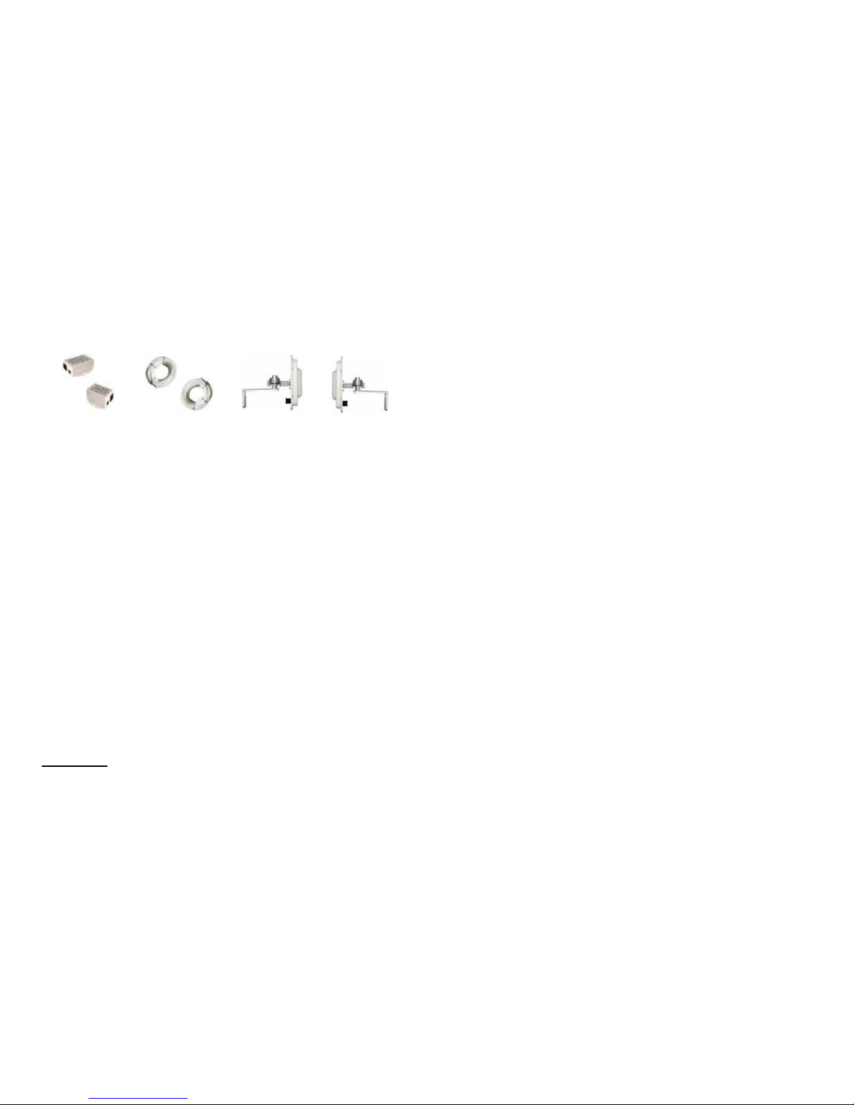
unit and accessories. You should have all the parts shown
below. In addition, you will find AC power cords and a pair of short
Ethernet jumper cables (patch cords).
STEP 1: Assemble the square tube to the back of the Q-BridgeTM unit
using 4 nuts. Don’t overtighten, just needs to be moderately tight
.
STEP 2:
Decide which polarity you will be using, Horizontal or vertical.
We highly recommend using Horizontal polarity because there is a lot
less interference when using this polarity. When the unit is in Horizontal
polarity the RJ45 ethernet connector is in the lower right hand corner.
When the unit is in vertical polarity, the RJ45 ethernet connector is in
the lower left hand corner. NOTE: In order for the antennas to talk to
each other, both units must be mounted with the same polarity
.
STEP 3: Decide on the mounting location for the units. This is probably
the single most important part of the installation. For best performance
and longest distances, the units should be mounted outside within sight
of each other. If just shooting a short distance, the units can be
mounted inside and a link can be established thru a wall or window.
The Q-Bridge
TM
comes complete with a QwikClamp pole mounting
system which can be used to mount to an existing pole like a TV antenna or a CB Radio antenna pole. It also includes a wall mount bracket
that will allow attachment to the wall of a structure or possibly a tree.
We recommend that, if possible, the Q-Bridge
TM
be mounted high on
the wall of a house under an eave which will provide added protection
from snow and freezing rain and the sun .
TECH NOTE:
Microwaves travel in straight lines and they lose strength
quickly when going thru buildings and trees. If there are objects in the
microwave path, then useable distance will be reduced. If the target unit
is less than 1 mile away then you won’t have to worry too much about a
couple obstructions but if over 1 mile and there are some obstructions
in the microwave path, then the performance will be reduced.
POE Power Supplies
75’ CAT5e Shielded Outdoor
Q-Bridge™ Bridge Units with Qwik-
13
e. Create an online gaming link with a friend up to 4 miles away.
Reduce or eliminate extra fees you might be paying for online
access for gaming purposes. And have more bandwidth for the
increased complexity of future games including Voice and Video.
f. Create a secure link for remote video and network based security
cameras. The Q-Bridge
TM
works with all network based security
cameras. Create a streaming video conference link between
buildings. Because of the high 4.5Mb/sec bandwidth available
with the Q-Bridge
TM
, it easily supports streaming video technologies used for remote conferencing, like church meetings, business meetings, etc.
Appendix:
Federal Communication Commission Interference Statement
This equipment has been tested and found to comply with the limits for
a Class B digital device, pursuant to Part 15 of the FCC Rules. These
limits are designed to provide reasonable protection against harmful
interference in a residential installation. This equipment generates, uses
and can radiate radio frequency energy and, if not installed and used in
accordance with the instructions, may cause harmful interference to
radio communications. However, there is no guarantee that interference
will not occur in a particular installation. If this equipment does cause
harmful interference to radio or television reception, which can be determined by turning the equipment off and on, the user is encouraged to
try to correct the interference by one of the following measures:
• Reorient or relocate the receiving antenna.
• Increase the separation between the e quipment and receiver.
• Connect the equipment into an outlet on a circuit different from
that to which the receiver is connected.
• Consult the dealer or an experienced radio/TV technician for
help.
• FCC Caution: Any changes or modifications not expressly approved by the party responsible for compliance could void the
user's authority to operate this equipment.
This device complies with Part 15 of the FCC Rules. Operation is subject to the following two conditions: (1) This device may not cause
harmful interference, and (2) this device must accept any interference
received, including interference that may cause undesired operation.
Page 3

12
lar house color. Only non metallic enamel or latex paints should be
used. If a paint with metal content is used, it will block the microwaves
and cause reduced performance.
7.TINTED WINDOWS – Tinted windows are made by applying a metal-
lized film to the window. If a window has tinting, it will usually block the
microwaves and cause reduced performance of the Q-Bridge
TM
. Concrete walls are also a significant barrier to microwave signals. Aluminum siding in houses is also a barrier to microwave signals. Wood
frame houses covered with brick or stucco are pretty transparent to microwave signals and they will reduce the signal strength but the signal
will still pass thru the structure. We are bringing this up to you so you
can better understand possible causes of performance issues
8.POE POWER SUPPLY – The Power Over Ethernet (POE) power
supply supplied with the Q-Bridge
TM
is a high quality auto-ranging and
highly regulated switching power supply. It meets the IEEE 802.3af
standard for Power Over Ethernet adapters. It will work over a wide variety of input voltages. It has built-in surge, overload and short circuit
protection. If the power supply light is not lit, then there is most likely
something wrong with the power supply or the wall outlet. If the power
supply light is blinking then there is probably some short circuit between
the power supply and the Q-Bridge
TM
electronics or possibly a dam-
aged Q-Bridge
TM
.
9.VOICE OVER IP (VOIP) – The Q-Bridge
TM
supports all VOIP stan-
dards making it possible to use VOIP phones across any Q-Bridge
TM
link.
10.TYPICAL APPLICATIONS:
a. Internet access sharing – share internet access with a friend or
family member
b. Link your Home Office to your Main Office - you can access
shared files and folders as well as print to the main office printers
and use other shared network devices remotely
c. Link multiple building networks together – A company with multi-
ple buildings will find the Q-Bridge
TM
an inexpensive way to link
their buildings together. Up to 4 buildings can be linked seamlessly using Q-Bridge
TM
wireless bridges.
d. Add a high speed link between your home network and a PC in
your remote studio or office which is located in an outbuilding on
your property.
3
STEP 4:
Mount the QwikClamp pole mount bracket to the tube in the
back of the Q-Bridge
TM
. Be sure to be mindful of the antenna polarity
as discussed above. The bracket can be attached to give up-tilt or
down-tilt for the antenna. Down-tilt is used if the sending antenna is
higher in elevation than the receiving antenna and up-tilt is used when
the sending antenna is lower than the receiving antenna. For down-tilt,
the bracket is installed on the square tube with the adjustment screw
pointing towards the right and for up-tilt the bracket is installed on the
square tube with the adjustment screw pointing towards the left. For
both cases, the bracket should be installed with the adjustment screw
under the square tube. The bracket can be installed at any length along
the square tube depending on how much standoff from the wall or pole
is desired. We typically recommend installing the bracket about half
way along the square tube.
STEP 5:
Attach the wall mount bracket to a wall using screws (not in-
cluded). Be sure to seal any screw holes in the wall with sealant to
avoid any water damage to the wall. Attach the QwikClamp bracket to
the installed wall mount bracket or to an existing pole. The speedbolt
clamp has two mounting orientations, one for smaller poles and one for
larger poles. Use whichever seems best. Tighten the speed bolt lightly.
STEP 6: Point the antenna towards the receiving antenna. Pointing is
achieved by visually sighting the location of the receiving antenna and
then moving the antenna to point in that direction. Tighten the speedbolt
and the locking nut once rotation is set. Tighten the bracket elevation
adjust screw once proper up/down angle is set.
TECH NOTE:
Because of the specially designed wide beamwidth antenna, pointing is not critical and simply pointing in the general direction
of the receiving antenna will yield good results.
STEP 7: Install the cable thru the patent pending field replaceable RJ45
waterproof connector system.
a. Trim about ½ the length of the bayonet tab from the CAT5
cable connector. This trimming is required to prevent interference when the RJ45-ECS cable feedthru is screwed into the
RJ45-ECS housing
b.
Feed the trimmed CAT5 cable RJ45 connector thru the
feedthru assembly as shown. There may be a rubber “skin”
on the compression gasket assembly. Just remove this by
grasping with the fingers and tearing it away
c. Slide the compression gasket insert into the compression
gasket assembly until it is flush with the end of the assembly
Page 4

4
d.Install the compression nut and tighten loosely
e. Screw the entire feedthru assembly into the RJ45-ECS hous-
ing which is already mounted in the enclosure. There should
be a rubber gasket between the two assemblies. Tighten the
feedthru assembly to create a seal
f. The final step is to tighten the compression nut until the gas-
kets are tight around the Cat5 cable
Disassembly
a. Loosen the compression nut to relieve pressure on the Cat5
cable
b.Unscrew the feedthru assembly from the RJ45-ECS housing
c. Using a small screwdriver depress the RJ45 bayonet lock to
release the RJ45 connector from the socket
STEP 8: Route the outdoor CAT5 cable from the Q-BridgeTM unit into
the building. Make sure to seal any holes you make with sealant to prevent water damage. Tie wrap the cable to secure it so it won’t flap in the
wind. We recommend using black color tie wraps because they perform
better in an outdoor environment than the white color ones.
TECH NOTE:
The Q-BridgeTM comes with 75 feet of CAT5e shielded
outdoor rated cable. This should be long enough for most installations.
If additional length is required, you can purchase an RJ45 shielded coupler at most electronics stores. The coupler won’t work very long outside but are fine for inside use. You can add up to a total of 225 additional feet of Cat5e cable without affecting performance.
STEP 9: Install the POE Power Supply. Be sure to plug in the cable
going to the Q-Bridge
TM
before plugging the unit into the wall. This will
avoid any damage to the Q-Bridge
TM
which could be caused by plugging in a “hot” connection. There is no problem plugging and unplugging the computer/router cable with power applied, only the POE connection. Once the POE power supply is plugged into the wall and the
system is OK, the green light on the power supply will light and stay lit
as long as the system is in operation. Because the Q-Bridge
TM
is designed to take such a small amount of power, it is recommended that it
be left powered up 24/7.
TECH NOTE: The Q-BridgeTM POE power supply is specially de-
signed to offer overload and short circuit protection. It also offers surge
protection from lightning to protect your equipment like routers,
switches, hubs, computers and gaming consoles.
11
3.SUN AND HEAT– The Q-Bridge
TM
is constructed of all UV protected materials so it will survive for many years in the most extreme of
solar environments (ie; an Arizona rooftop during the summer). The unit
has been tested and qualified for constant operation at over 165 deg F
ambient temperature. Even though the Q-Bridge
TM
is designed for
long term survivability in extreme environments, we would still recommend that the unit be mounted in a more protected location, like under
a roof eve, if possible. Of course if line of sight is better with the antenna mounted in a non-protected environment then we would recommend the better line of sight mounting location.
4.LIGHTNING – Lightning is the single worst enemy of outdoor elec-
tronics equipment. No electronics will survive a direct strike but there
are close proximity strikes that can cause huge electrical fields to be
generated which can damage electronic equipment. We have taken
special care in the design of the Q-Bridge
TM
unit to ensure proper
grounding of the electronics inside the enclosure to prevent damage
from electrical storms. We use only the more expensive shielded
CAT5e cable to prevent electrical surges being generated within the
cable. Make sure that the POE Power Supply is plugged into a 3 prong
grounded outlet. This will prevent damage from surges to equipment
inside the house. We highly recommend that the mounting pole or the
wall mount bracket be grounded to give additional protection against
surges caused by lightning. These can be grounded by attaching a wire
to the metal and running the wire to a good earth ground (cold water
pipe, copper stake driven in the ground). If there are metal rain gutters
on the house, the wire can be run from the wall mount bracket to the
metal gutter and then another wire can be run from one of the downspouts to an earth ground. Because of the random nature of lightning,
we cannot warrant the Q-Bridge
TM
against damage from lightning. We
will, however, repair any unit which fails within the warranty period at a
greatly reduced service fee.
5.INTERNET ACCESS SHARING – The Q-Bridge
TM
is the perfect
equipment to share your internet access with a friend or family member
up to 4 miles away. Using the Q-Bridge
TM
provides a seamless connection between networks and you can share the internet access available on the main network with the remote network. Please take note
that certain internet service providers may not approve of this and in
some cases, they may consider this to be illegal. It’s best before sharing your internet connection that you check with your internet service
provider to make sure you aren’t in violation of your service contract.
6.PAINTING – The Q-Bridge
TM
unit can be painted to match a particu-
Page 5
10
remote units to each of the Q-Bridges
TM
on the WIRELSS | BRIDGE
SETTINGS page. So each Q-Bridge
TM
unit in a quad arrangement will
have the MAC addresses of the other 3 remote units programmed into
its MAC Address table. The MAC address of each unit is shown on the
STATUS page.
9. CLIENT MODE:
In addition to being a bridge device, the Q-
Bridge
TM
can also be used as a client device. A client device is one
that talks to an access point. You would need to have an available access point in your area in order to use the Q-Bridge
TM
as a client device. To change to client mode: WIRELESS | BASIC SETTINGS | Mode
= Client. Settings such as Channel and Security Encryption would need
to be set to match the access point.
TECH CORNER
Additional Information you may find useful
1.
DHCP – DHCP is used to automatically assign IP addresses to com-
puters on the network. The DHCP server that is responsible for assigning the IP addresses is usually the Router that connects your network to
the internet but it could be your computer if you are using Microsoft
Internet Sharing. Because of the seamless and transparent nature of
the Q-Bridge
TM
connection, DHCP requests and responses will be
passed across the wireless link. We normally recommend that only 1
DHCP server exists on a given network. It’s not a huge issue if two or
more are present on the network but it’s cleaner if only 1 DHCP server
is available on the network to avoid IP confusion. IP confusion would
occur if two machines on the same network were given the same IP
address. The machines would report an IP conflict error if this were the
case. Keep in mind that with the Q-Bridge
TM
link the two connected
networks will appear as one network because they are being bridged
seamlessly thru Q-Bridge
TM
wireless connection.
2.RAIN, SNOW, ICE – The 2.4GHz frequency being used by the QBridge
TM
will not be affected by heavy rain or falling snow. You should
not see any performance degradation due to inclement weather. If snow
or ice collects on the front bubble of the antenna, you may see some
reduced performance assuming you are shooting a long distance
( >3miles) and the ice or snow buildup is greater than 1” thick on the
surface of the bubble. For this reason, we suggest mounting under an
eave of a house if feasible for your particular situation.
5
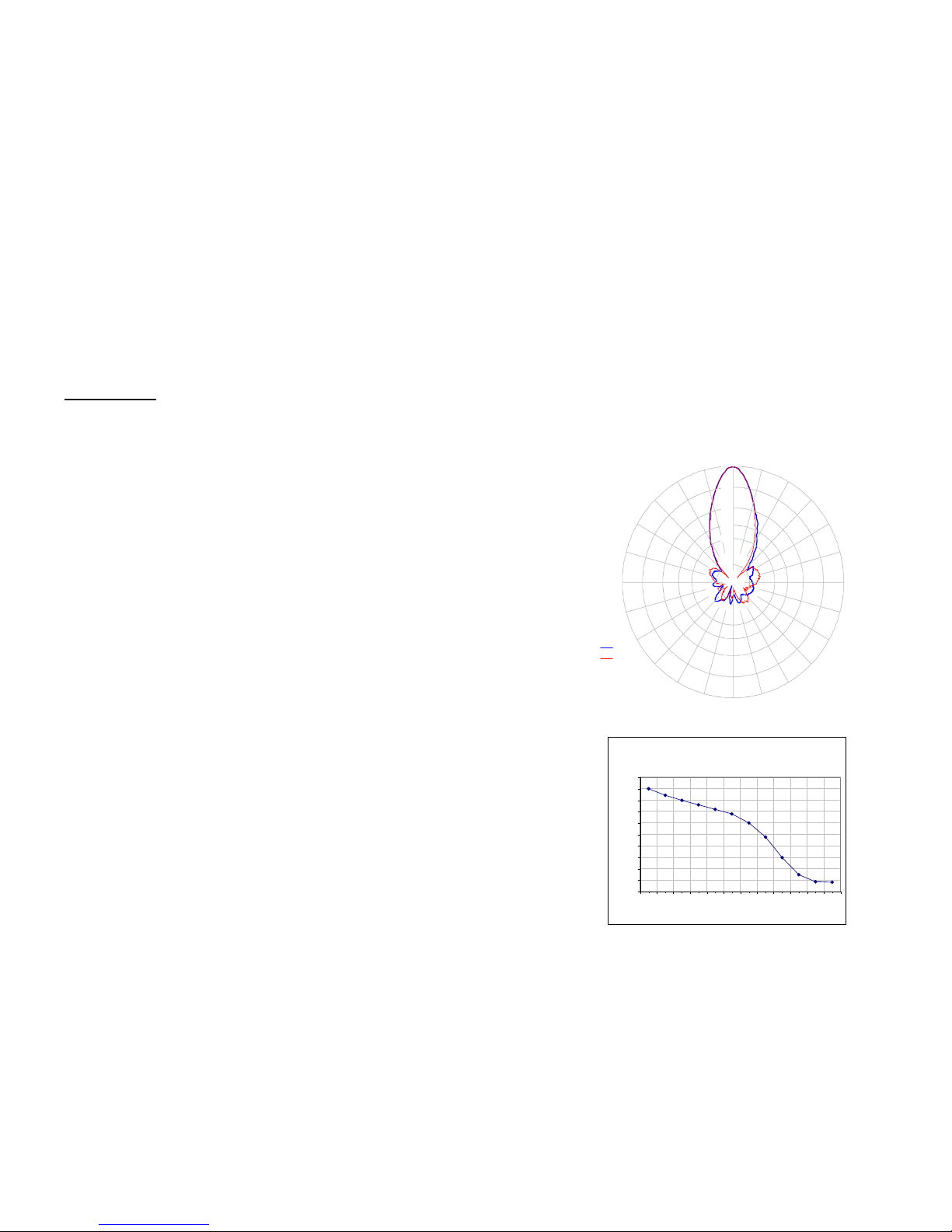
Antenna Pattern
0
15
30
45
60
75
90
105
120
135
150
165
180
-165
-150
-90
-75
-60
-45
-30
-15
h
v
-1
-3
-6
-10
-25
2400.0 MHz
When connecting to routers, switches and hubs you will use a
straight thru cable normally called a patch cord. When connecting
directly to a computer or gaming console, you will use a crossover
cable.
STEP 10: Repeat the procedure for the other side of the link up to 4
miles away. After the installation is completed on both sides of the Q-
Bridge
TM
wireless bridge link the networks will be connected and the
link will be established. The Wireless Bridge is transparent so that it’s
just like having a CAT5 cable strung between the two devices or networks.
QwikBri dge Typical Thruput vs Dis t ance
Line of Site = No Obstructions Between Antennas
0
0.5
1
1.5
2
2.5
3
3.5
4
4.5
5
<=1 1.5 2 2.5 3 3.5 4 4.5 5 5.5 6 6.5
Miles
Mb/sec Thru pu t
Page 6
6
Specifications
Why can’t I get 11Mb/sec thruput like those other guys advertise? The truth is that
all 802.11b devices on the market operate in half duplex mode which cuts the realistic
thruput in half so theoretical maximum is 5.5Mb/sec. Because of 128bit encryption and
other communication overhead within the devices, typical thruput maximums are 4.0 to
4.5Mb/sec. We believe in only advertising tested and verified actual thruput numbers
so you get what you expect and not some pie-in-the-sky empty promise. Refer to the
chart above for actual thruput vs distance test results.
General
Standards
802.11b (Wlan), 802.3(LAN), 802.3af
(POE)
Modulation DSSS (DPBSK, DQPSK, CCK)
Certifications FCC / CE
Radio Specifications
Operating Frequency 2400 to 2497MHz
Channels
USA/Canada 11; Japan 14; France 4;
Europe 13
RF Output Power
(software selectable)
250mW, 200mW, 150mW, 100mW
Maximum EIRP
+38dBm
Receive Sensitivity @ 11Mbps -87dBm
Security 64/128bit WEP, WPA or TKIP 802.1x
Remote Config (Web Based) By IP Address; thru Wireless or Ethernet
Antenna Specifications
Antenna Gain 14 dBi
Antenna Beamwidth (V & H) 35 deg
Antenna Front to Back >18dB
Polarization Horizontal or Vertical
POE Specification
Power Over Ethernet Injector (CE
Approved / 802.3af Compliant)
INPUT: 90 – 264VAC @ 47 – 63Hz OUTPUT: 48VDC @ .35A
Mechanical Specifications
Color
White or Gray
Dimensions (L x W x H)
10.75” x 10.75” x 2.6” (267 x 267 x 67mm)
Weight
29 oz (800 g)
Ethernet Connector
Field Replaceable Waterproof RJ45
Cable (75’ long)
CAT5E Outdoor Rated Shielded Cable
Mount
Wall or Pole Mount
Environmental Specifications
Operating Temperature
-40 to 167 Deg F (-40 to 75 Deg C)
Humidity
0 to 100% RH
Wind Loading (125MPH survivability)
100MPH / 28lbs; 125MPH / 43lbs
9
TECH NOTE:
You may want to play around with different settings to
see what works best for your particular link. The measurement you
would use to compare settings would be to measure the actual thruput
by timing the transfer of data across the link. One program that we have
found useful for determining thruput is DISKBENCH
(http://nodesoft.com/DiskBench/
).
6. SITE SURVEY:
The site survey is a very useful tool to determine
what wireless devices are within range of your Q-Bridge
TM
. Goto
WIRELESS | SITE SURVEY and click on REFRESH. The list will show
all wireless devices including the remote Q-Bridge
TM
unit (The remote
unit will have a blank SSID, for additional security, but can be identified
by its MAC address). The table will show channel #, MAC Address and
relative signal strength of all the devices within the range of the Q-
Bridge
TM
. This is useful to see where possible interference could be
coming from in case you are experiencing performance problems.
7. ANTENNA ALIGNMENT:
Because of the special antenna design,
antenna alignment is simple using just visual alignment and an electronic alignment isn’t necessary. If you’d like to use the antenna alignment tool, make sure that both sides of the link are attached to an active network, then goto WIRELESS | ANTENNA ALIGNMENT | ENTER
ANTENNA ALIGNMENT MODE then click on Antenna Alignment Meter. This will bring up a bar graph display showing RSSI (signal
strength) and SQ (signal quality). It’s normal for these numbers to
bounce around a bit but they are useful to get an average reading. You
can move the antenna while watching the numbers to get a peak signal.
Due to terrain variances and reflections this peak signal might cause
the antenna to be tilted away slightly from visual alignment. NOTE:
After antenna alignment both sides of the link will need to be rebooted.
This can be accomplished by unplugging the POE power supply and replugging it in or if you have computer access to the unit by clicking on
the reboot button on the STATUS page.
8. MESH NETWORK:
You can add an
additional 2 Q-Bridge
TM
units to create a
mini mesh network. This is useful if you
want to connect 4 buildings together. All
Q-Bridge
TM
units must have the same
settings for Encryption and Channel.
Each unit must have a unique IP address.
To add another Q-Bridge
TM
you will
need to add the MAC addresses of any
SAMPLE MESH NETWORK
Page 7

8
WIRELESS is used for setting up client security if the unit is reconfigured as a client device. For bridge security setting you must set security
under the BRIDGE SETTINGS.
TECH NOTE:
When setting encryption you must setup both sides of the
link to have identical encryption keys. You can setup the remote unit
first and then the local unit last in order to be able to configure both
units from 1 location across the wireless link. HEX Encryption keys can
use the letters A to F, a to f and numbers 0 to9. The more random the
key the more secure the code. For 128 bit encryption (most secure)
using a HEX code takes 26 characters in the excryption key. You can
also set ASCII codes which only take 13 characters and can be any
ASCII character but we recommend a HEX code as being the most secure.
a.SSID Broadcast is set to disabled by default. We recommend that you
keep this disabled for additional security. You may also change SSID to
a personal word. SSID doesn’t need to be the same on both units. It’s
for information purposes only.
4. CHANNELS:
The Q-BridgeTM default channel is set to channel 2.
The only reason you might want to change the channel is if you experience lots of interference from local wireless systems which are operating on the same channel. To change the channel go to WIRELESS |
BASIC SETTINGS and change the channel. Both sides of the link must
be on the same channel and if setting both units from 1 location, always
set the remote unit first and the local unit last.
5. TRANSMIT POWER
(Tx Power): Normally there wouldn’t be any
reason to change the power setting. The factory default setting is
200mW which should be good for most applications. If you are trying to
shoot a longer link or you have some objects (trees, buildings) between
your Q-Bridge
TM
units, then you may want to turn up the power to
250mW. If you have a shorter link you will actually get better performance if you turn down the Tx Power. This is because at close range
there is too much power and it has a tendency to overload the input
stage of the units and performance degrades. Use the following general
guideline for reference:
Power Level Recommended Distance
100mW <1 mile
150mW 1 to 1.5 miles
200mW 1.5 to 2 miles
250mW 2 to 4 miles
7
Software Settings - We strongly recommend
that you create a working plug and play link before
making ANY changes to the software settings
1. There is an HTML management system built into every Q-BridgeTM
unit. This management system can be accessed thru the CAT5
ethernet cable connection or thru the wireless connection, so you can
manage both sides of a link from 1 location.
2. To access the Q-Bridge
TM
units, your computer/game console must
be on the same subnet as the Q-Bridge
TM
unit. For instance the Q-
Bridge
TM
units come configured on subnet 192.168.1.xxx Your computer/game console must be on this subnet to be able to talk to the
units. If using Windows goto MY NETWORK PLACES | VIEW NETWORK CONNECTIONS | LOCAL AREA CONNECTION, then click on
the SUPPORT tab to see the IP address. If your IP address starts with
192.168.1.xxx then you will be able to communicate with the Q-
Bridge
TM
. If your address is something else like 192.168.0.xxx you will
need to first manually configure your machine’s IP address temporarily
to be on the 192.168.1.xxx subnet, access the Q-Bridge
TM
units so
that you can change their IP address to match your original subnet,
then switch your machine back to the original settings. Before changing
any settings on your machine write down all the numbers on the SUPPORT tab under DETAILS. This will allow you to reset the machine
back to the original settings after making any changes. The Q-
Bridge
TM
unit #1 comes pre-configured with IP address 192.168.1.220
and Unit #2 comes pre-configured with IP address 192.168.1.221
3. SECURITY:
Security is pre-configured with system passwords,
128Bit encryption, SSID broadcast disabled and Mac Address verification pre-set. This is so that you can setup a plug and play link and have
confidence that the link is secure and that your data and network is
safe. Once you feel comfortable with the system we would recommend
the following security changes:
a.Change the access password on each side of the link by going to
PASSWORD. The factory default user name is: PAW and the default
password is: pawhero. Both password and user name are case sensitive.
b.Change the 128bit encryption code by going to WIRELESS | BRIDGE
SETTINGS | SET SECURITY . ATTENTION: The SECURITY tab under
 Loading...