

connektgear 27-3020/WIFI, 27-3020/WIFI/1 Install & Set-up Manual
Install & Set-Up Guide
All In One Socket
Starter Kit
WIFI USB
Charging
Network
Ports
Powerline
Technology

Connekt Gear is a brand of Group Gear Ltd
This Install Guide is for:
WiFi CONNEkT Starter Kit
and
WiFi CONNEkT Add-On Sockets
GROUP GEAR LTD
Email • technical@groupgear.co.uk
Skype • technical@groupgear.co.uk
Website • www.groupgear.co.uk
Find us on YouTube • WiFi CONNEkT

CONTENTS
Important Safety Warnings 4
Socket Labels 5-6
Installation Regulations 7
Installation Instructions 8-9
Safety Approvals 10
Product Specifications 11-12
Changing the IP Address 13-16
Set-up - SSID Repeat 17-26
Set-up - Access Point (wireless) 27-39
Set-up - Access Point (wired) 40-50
Switching Configuration Mode 51-53
Bandwidth Throttling 54-57
Time Settings 58-60
Global WiFi Control 61-63
Factory Restore 64-67
3

We recommend using a qualified electrician for installation.
Please ensure that these instructions are read carefully and
fully understood before commencing with installation.
IMPORTANT SAFETY WARNINGS
CONTACT WITH MAINS ELECTRICITY CAN CAUSE SERIOUS INJURY OR DEATH.
• Do not open the back of WiFi CONNEkT Wall Socket as this will void your warranty.
• Do not store or install this product in areas of high humidity.
• Do not insert any foreign objects into the openings of the WiFi CONNEkT Wall Socket.
• Do not cover or block the holes on the rear of the unit as they serve as ventilation.
• Do not use water or substances such as paint thinners, alcohol or strong cleaning solutions to
clean the WiFi CONNEkT Wall Socket due to risk of damage to the plastic, electrocution or fire.
• Do not use the WiFi CONNEkT Wall Socket with a power supply different than 220-240 volts 50 Hz AC.
• To prevent fire hazard always use cable of the correct rating, size & type for the installation.
• Suitable for indoor use only.
• If the WiFi CONNEkT Wall Socket becomes damaged isolate all electrics and
seek the advice from a qualified electrician.
4
5
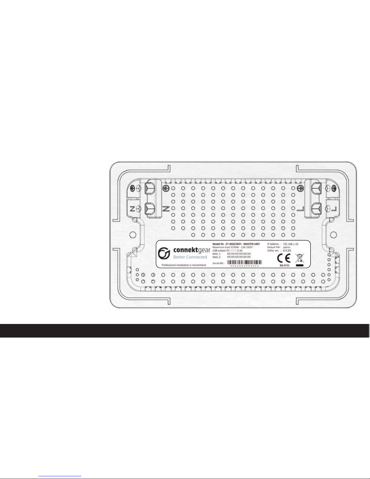
MASTER SOCKET PRODUCT LABEL
The product label is located on
the back of the unit and contains
unique details specific to
your device.
• Model number
• Power usage details
• USB charger details
• Powerline MAC address
• Ethernet/wireless MAC address
• Serial number
• Default password (refer
to user manual)
• IP Address (refer to
user manual)
• Software version
PLEASE NOTE:
MAC 1, MAC 2, Serial NR & Softw. ver
will vary for each unit
Warranty is void if the label
is removed.
6
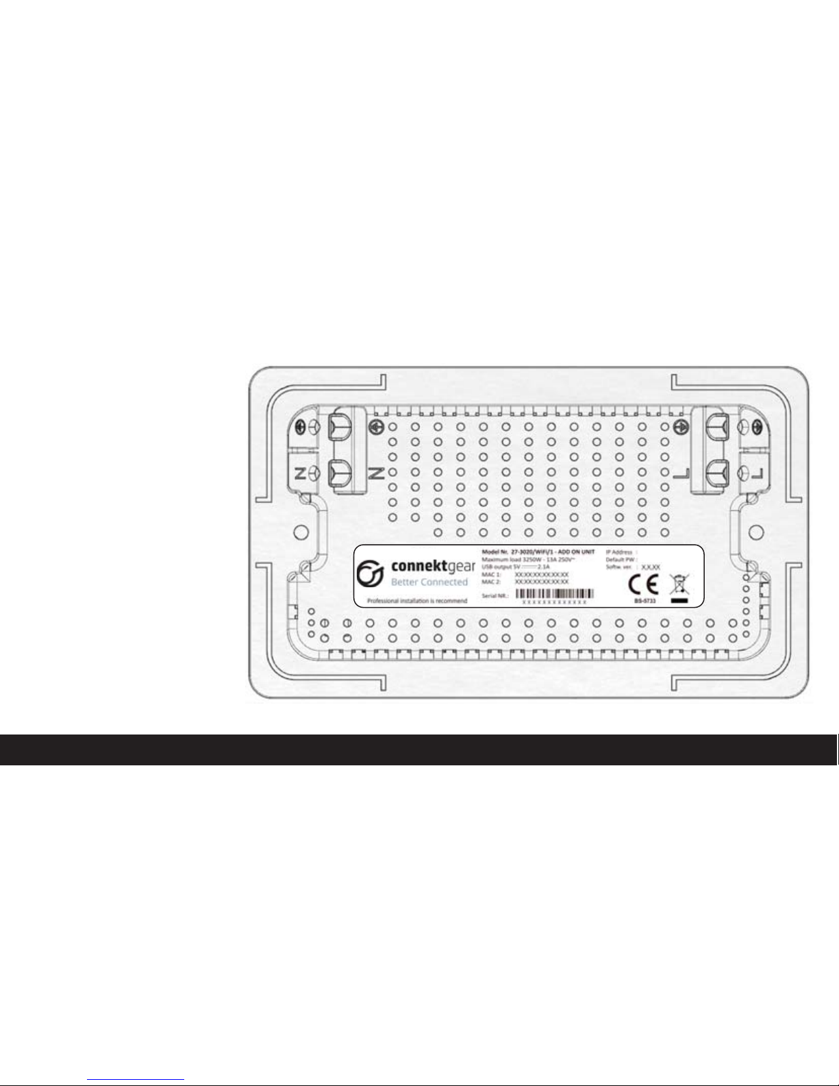
ADD-ON SOCKET PRODUCT LABEL
The product label is located on
the back of the unit and contains
unique details specific to
your device.
• Model number
• Power usage details
• USB charger details
• Powerline MAC address
• Ethernet/wireless MAC address
• Serial number
• Default password
• IP Address
• Software version
PLEASE NOTE:
MAC 1, MAC 2, Serial NR &
Softw. ver will vary for each unit
Warranty is void if the label
is removed.

INSTALLATION REGULATIONS
UNITED KINGDOM
The WiFi CONNEkT Wall Socket must be installed in accordance with the
latest edition of the IEE Wiring (BS 7671) Regulations & Building Regulations.
REPUBLIC OF IRELAND
The WiFi CONNEkT Wall Socket must be installed in accordance with the
ETCI National Rules for Electrical installations.
7

8
INSTALLATION INSTRUCTIONS
1. Switch off the mains power supply in the consumer unit (fuse box).
2. If retro fit remove the existing wall socket from the wall.
3. Prepare the mounting surface area clearing away any plaster debris
and dust from the inside the mounting box.
4. If using the included spacer slide it over the back of the wall socket.
5. Following the diagram overleaf push the cables into the relevant terminal blocks.
(features dual earth terminals, either or both can be used).
6. All earth wires must be sleeved and terminated to the backbox.
7. Tighten the terminal screws firmly and securely.
8. This device must be earthed.
9. Screw the wall socket securely to the wall using the screws provided.
10. Switch the mains supply back on in the consumer unit (fuse box) when
the installation has been correctly completed.
11. Before use we recommend that a socket test is carried out using a socket tester.

9
NOTE
Please follow installation guide diagram for best practice.

SAFETY APPROVALS
• EN300328
• EN301489
• EN62311
• EN50561
• EN50412
• EN55032
• EN61000-3-2
• EN61000-3-3
• BS5733
• Complies with UK Building Regulations 2010
approved document M, Volume 2, Section 4.
10

11
PRODUCT SPECIFICATIONS
POWERLINE, WIRELESS, USB CHARGING & GENERAL SPECIFICATIONS

12
POWERLINE SPECIFICATIONS
• Ring main circuit distance: Up to 300m
• High speed data transfer: 500Mbps
• Network: 10/100Mbit
802.11N WIRELESS SPECIFICATIONS
• Signal range: Up to 15m
• High speed data transfer: 300Mbps
• Frequency: 2.4GHz
• MIMO technology - ensures minimal errors,
optimal performance and signal range
USB CHARGING SPECIFICATIONS
• Surge and spike protection
• 2.1 Amp Output
GENERAL SPECIFICATIONS
• Supports up to 8 sockets
(1 x Master Socket, 7 x Add-On Sockets)
• Modes: Access Point, Extend/Repeat (SSID)
• User Interface (UI) via web browser
• Standards: IEEE 802.3, IEEE 802.3u, IEEE 802.3x,
auto MDI/X, IEEE 1901, IEEE 802.11 b, g, n, IEEE 802.1p
• Protocols: CSMA/CA (Powerline)
• Function buttons: WiFi on/off, Powerline pairing,
Device reset
• Simple retro fit socket
• Fits into a standard BS double gang backbox
• 25mm Backbox will require the enclosed spacers
• Interchangeable front fascia
• Downloadable Firmware updates
• Operating temperature: 0° to 40°C
• Operating humidity 10–90% max relative humidity, non-condensing
• Storage humidity 5–95% max relative humidity, non-condensing

13
IP ADDRESS - SSID REPEAT
HOW TO CHANGE THE WALL SOCKETS DEFAULT IP ADDRESS
WHEN SETTING UP SSID REPEAT MODE
14
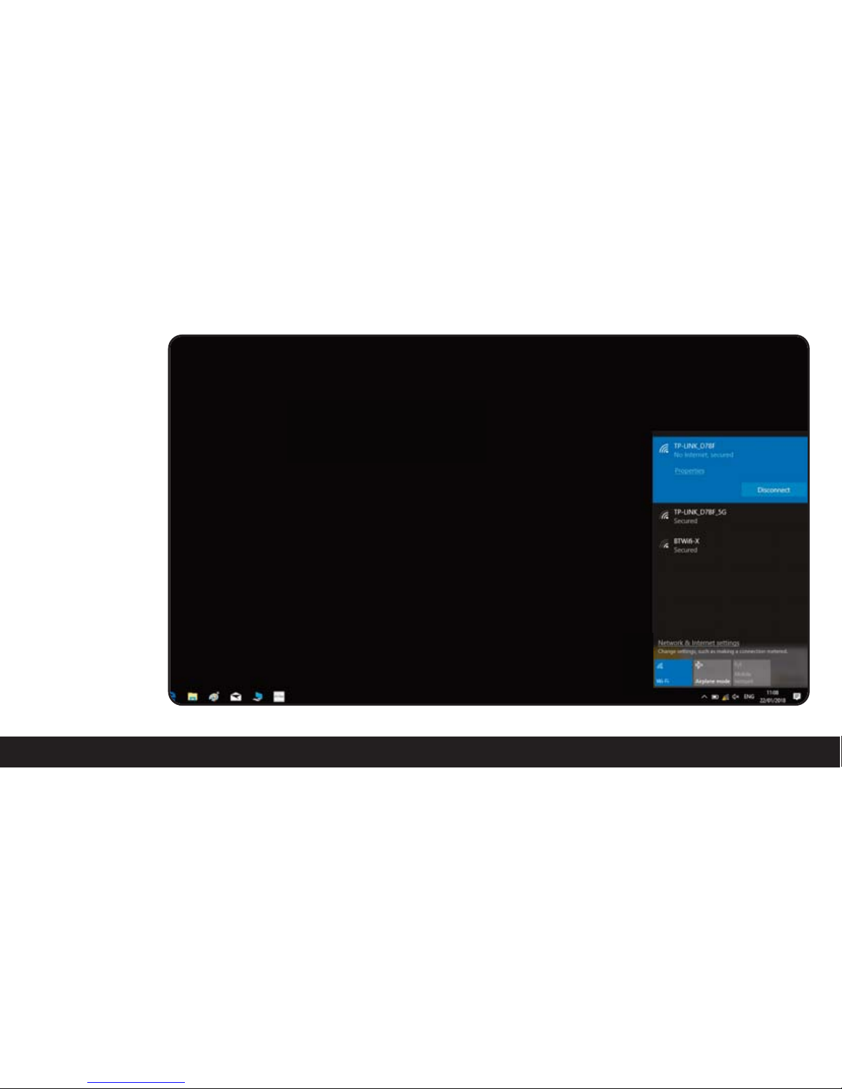
• To check if the
router you are
using has a different
IP scheme start
by connecting to
the router.
15
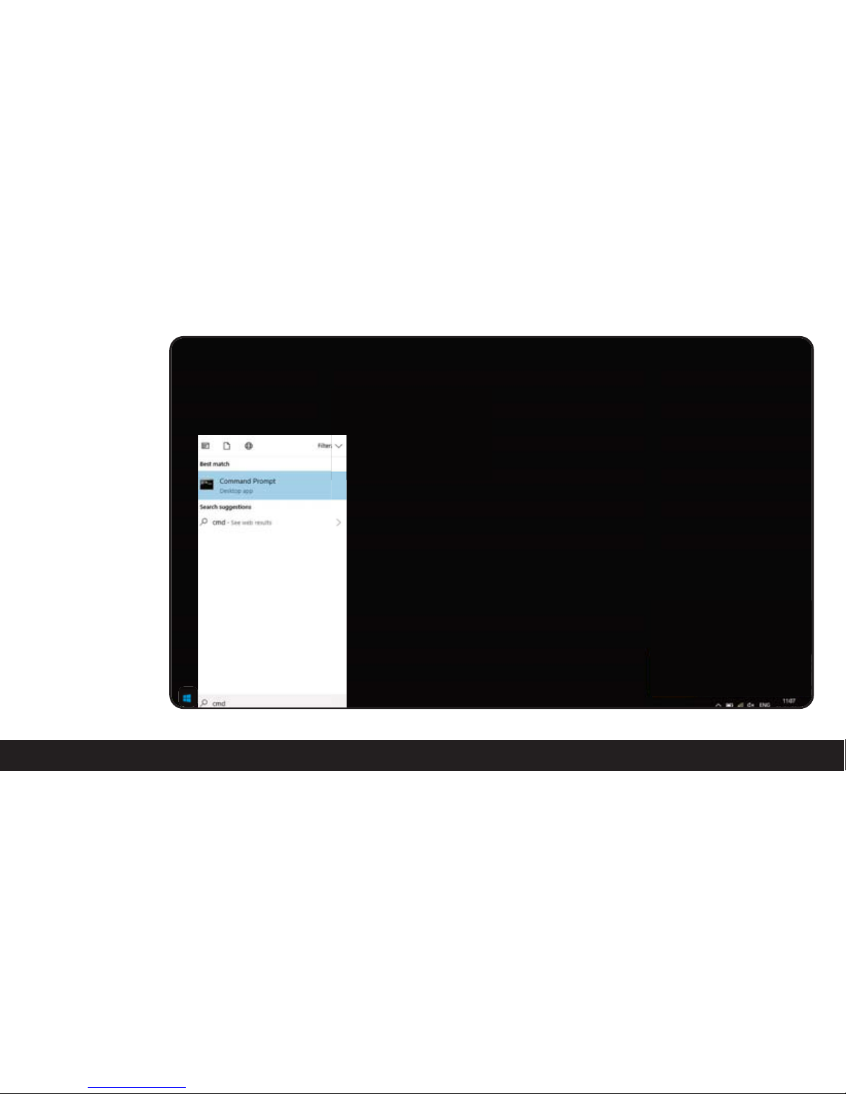
• Load the start menu.
In the search bar
enter CMD and
load command
prompt.

16
• Once the command
prompt has loaded
type in “ipconfig”
and hit enter, this
will come up with
a list of text and
numbers. The text
you need to look
for is “Default
Gateway” next to
this thereshould be
an IP address (a
series of numbers
separated by full
stops) you will need
to take note of the
numbers as they
will be used later on.
Next is to configure
the unit to your
chosen mode:

17
SET-UP - SSID REPEAT
ENSURE ALL THE WIFI CONNEKT WALL SOCKETS & ADD-ON SOCKETS
THAT YOU WISH TO USE ARE WIRED UP TO YOUR MAINS.
18
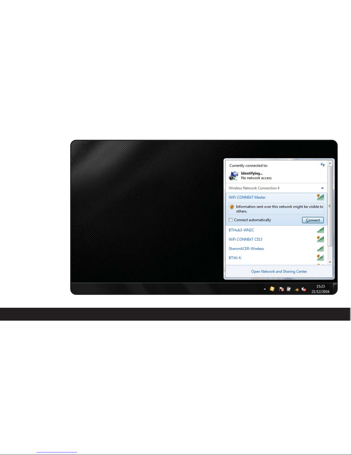
• Firstly connect to
the WiFi CONNEkT
Wall Socket. It will
be displayed as
“WiFi CONNEkT
Master“
19
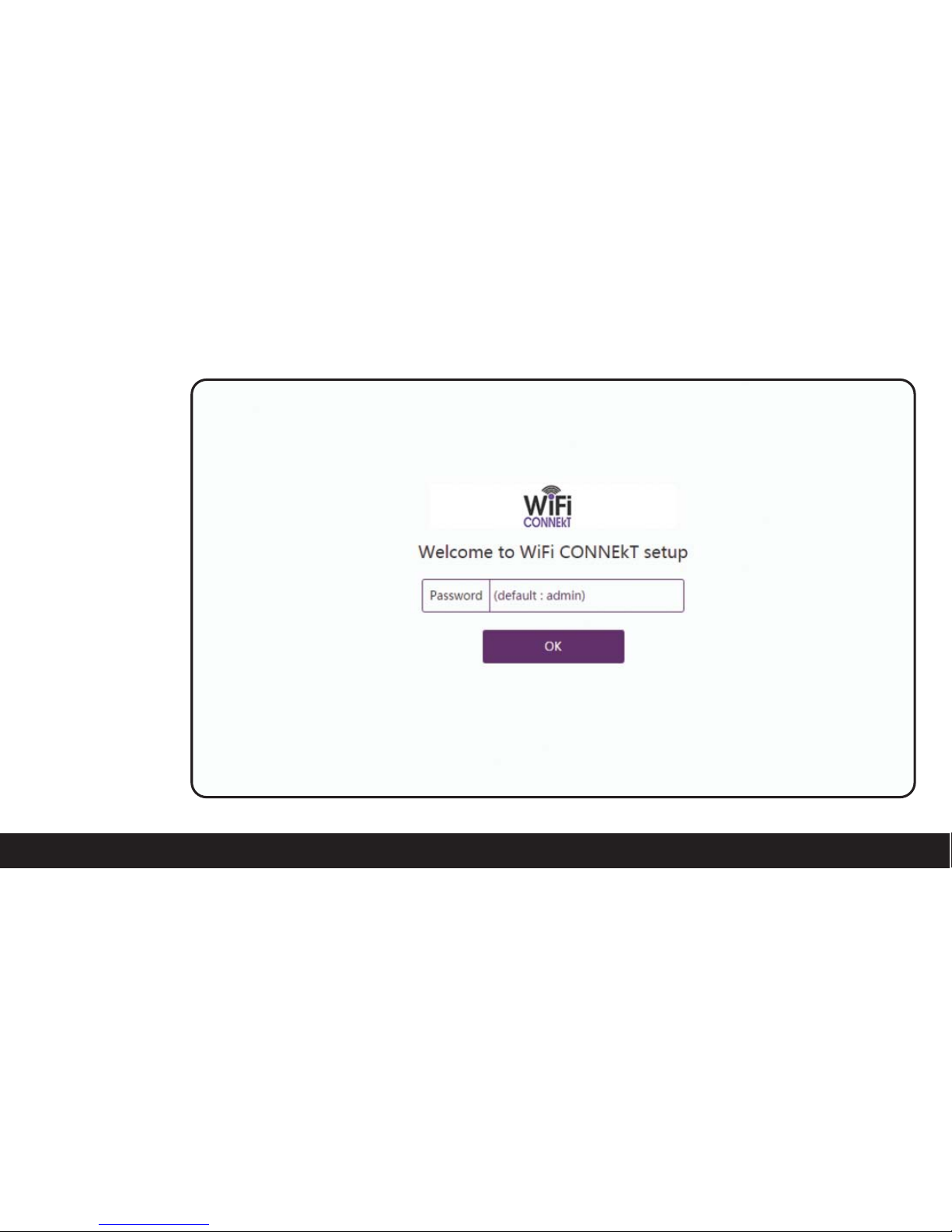
• Once connected to
the WiFi CONNEkT
Wall Socket we then
need to load up
a browser and
type in the
address bar the
IP address for the
WiFi CONNEkT
Wall Socket which
is: 192.168.1.10
(if not
changed)
• This will bring up
the log-in screen
where you will be
asked for a
password which is
set to: admin
• Once you have
entered the
password click OK
to continue.
20
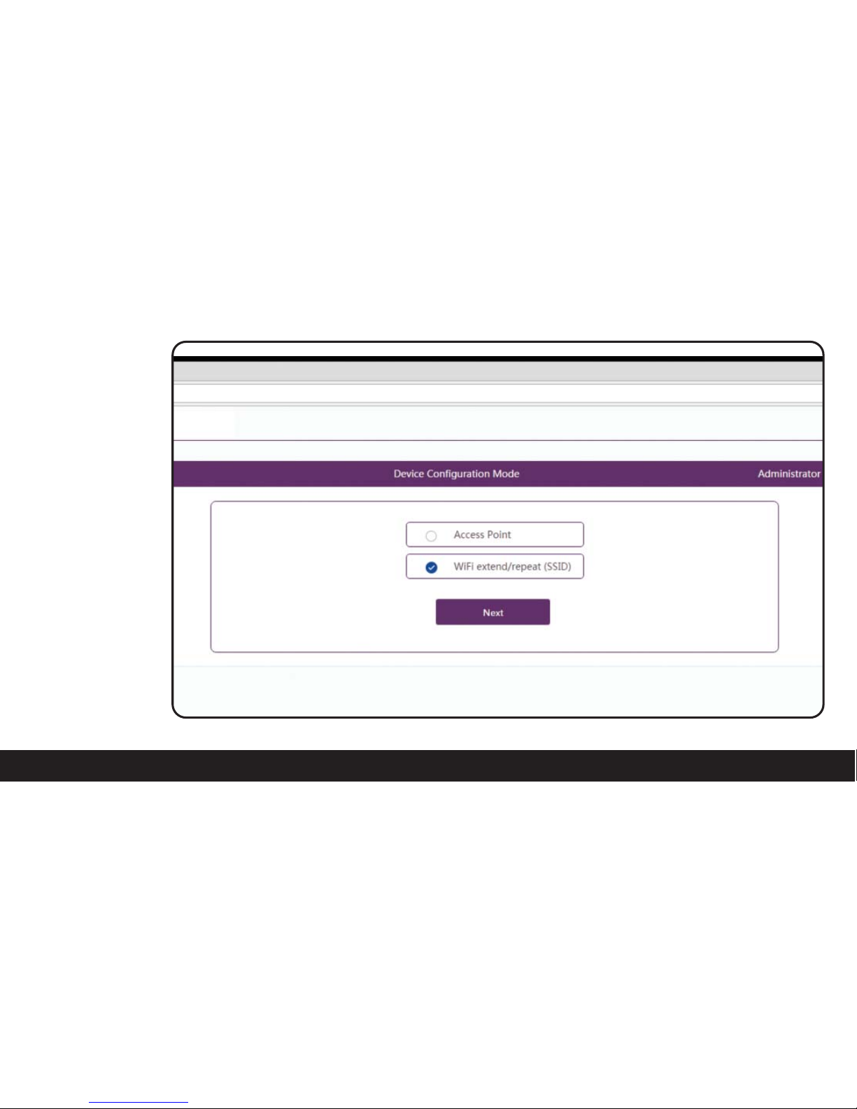
• Now you will need
to choose which
configuration mode
you would like to
set-up.
• In this instance
it will be:
WiFi extend/repeat
(SSID).
• Once you have
selected this option
click NEXT to
continue.
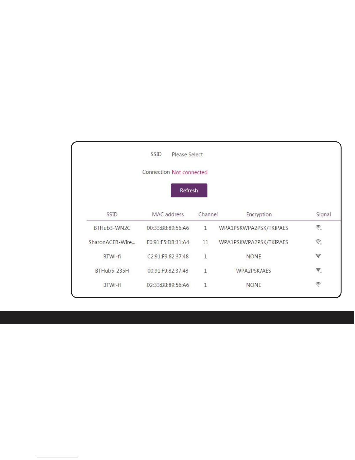
21
• Here there will be
a list of SSIDs that
are available to
repeat from. Select
the SSID that you
require.
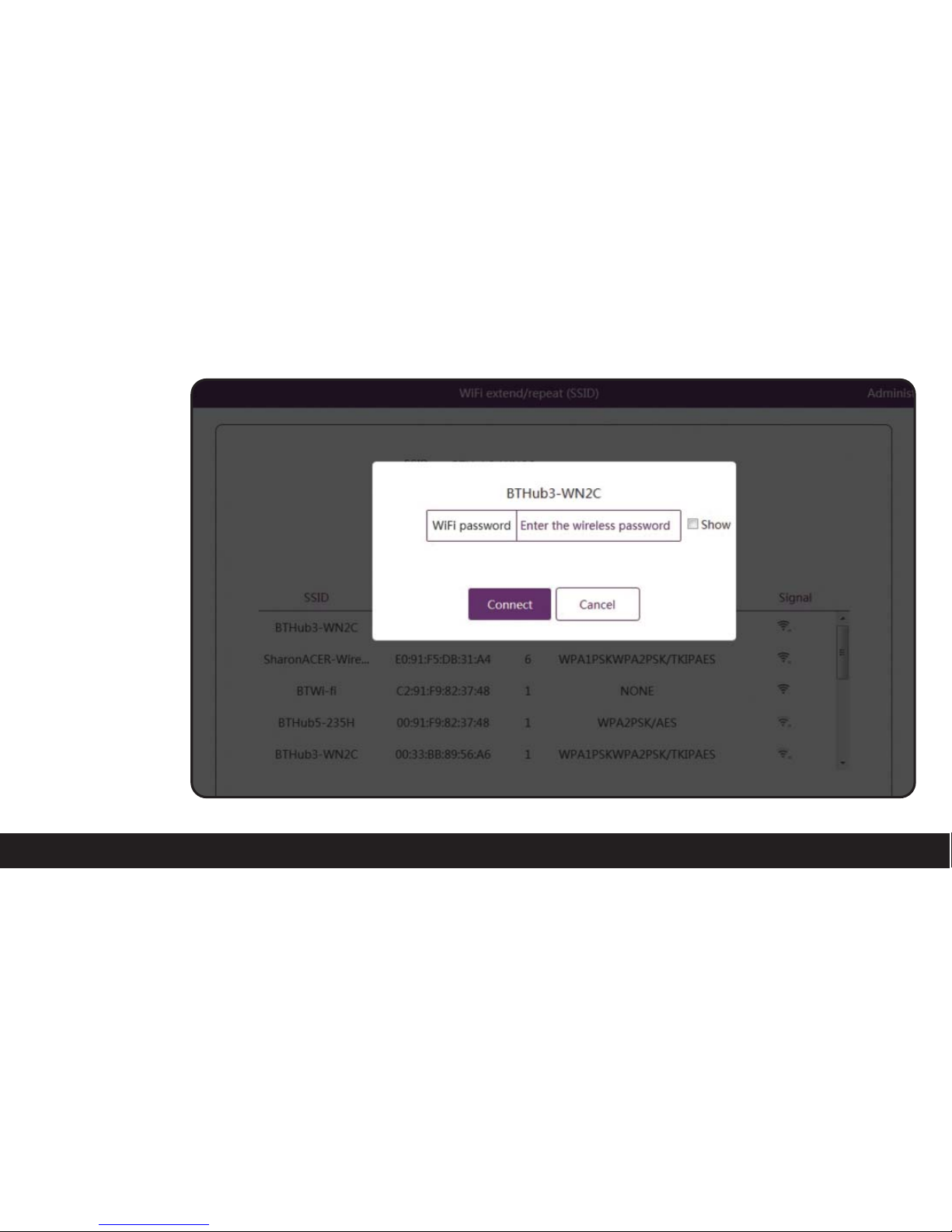
22
• Once you have
selected the
required
SSID you wish to
repeat from, you
will be asked to
enter it’s password.
• Once you have
entered the
password click
CONNECT to
continue.
 Loading...