

Page 1
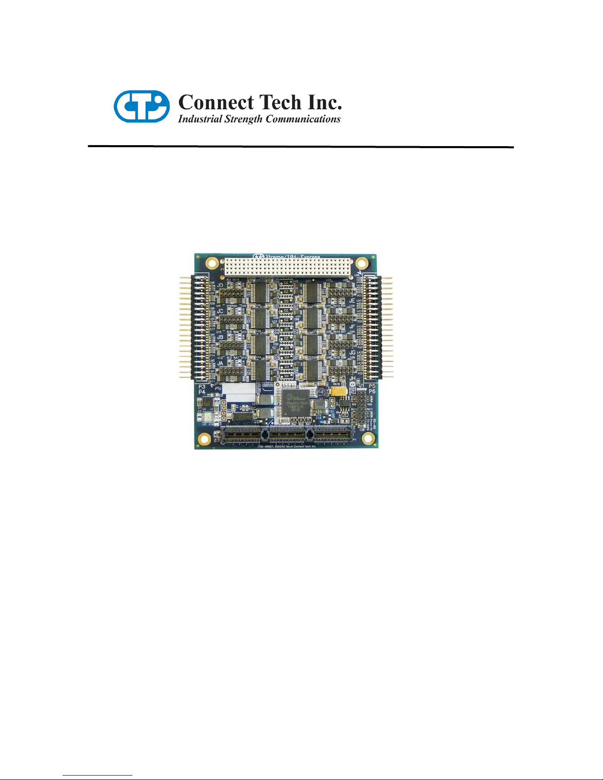
Xtreme/104-Express
User Manual
Connect Tech Inc
42 Arrow Road
Guelph, Ontario
N1K 1S6
Tel: 519-836-1291
Toll: 800-426-8979 (North America only)
Fax: 519-836-4878
Email: sales@connecttech.com
support@connecttech.com
Web: www.connecttech.com
CTIM-00045 Revision 0.00 July 30, 2008
Page 2

Connect Tech Xtreme/104-Express User Manual
Limited Lifetime Warranty
Connect Tech Inc. provides a Lifetime Warranty for all Connect Tech Inc. products. Should this
product, in Connect Tech Inc.'s opinion, fail to be in good working order during the warranty
period, Connect Tech Inc. will, at its option, repair or replace this product at no charge, provided
that the product has not been subjected to abuse, misuse, accident, disaster or non-Connect Tech
Inc. authorized modification or repair.
You may obtain warranty service by delivering this product to an authorized Connect Tech Inc.
business partner or to Connect Tech Inc. along with proof of purchase. Product returned to
Connect Tech Inc. must be pre-authorized by Connect Tech Inc. with an RMA (Return Material
Authorization) number marked on the outside of the package and sent prepaid, insured and
packaged for safe shipment. Connect Tech Inc. will return this product by prepaid ground
shipment service.
The Connect Tech Inc. Lifetime Warranty is defined as the serviceable life of the product. This
is defined as the period during which all components are available. Should the product prove to
be irreparable, Connect Tech Inc. reserves the right to substitute an equivalent product if
available or to retract Lifetime Warranty if no replacement is available.
The above warranty is the only warranty authorized by Connect Tech Inc. Under no
circumstances will Connect Tech Inc. be liable in any way for any damages, including any lost
profits, lost savings or other incidental or consequential damages arising out of the use of, or
inability to use, such product.
Copyright Notice
The information contained in this document is subject to change without notice. Connect Tech
Inc. shall not be liable for errors contained herein or for incidental consequential damages in
connection with the furnishing, performance, or use of this material. This document contains
proprietary information that is protected by copyright. All rights are reserved. No part of this
document may be photocopied, reproduced, or translated to another language without the prior
written consent of Connect Tech, Inc.
Copyright 2008 by Connect Tech, Inc.
Trademark Acknowledgment
Connect Tech, Inc. acknowledges all trademarks, registered trademarks and/or copyrights
referred to in this document as the property of their respective owners.
Not listing all possible trademarks or copyright acknowledgments does not constitute a lack of
acknowledgment to the rightful owners of the trademarks and copyrights mentioned in this
document.
Revision 0.00
2
Page 3

Connect Tech Xtreme/104-Express User Manual
Table of Contents
Limited Lifetime Warranty............................................................................................................................. 2
Copyright Notice ............................................................................................................................................ 2
Trademark Acknowledgment ......................................................................................................................... 2
Table of Contents ........................................................................................................................................... 3
Customer Support Overview .......................................................................................................................... 5
Contact Information........................................................................................................................................ 5
Introduction .................................................................................................................................................... 6
Features ...................................................................................................................................................... 6
Xtreme/104-Express Board Diagram ............................................................................................................. 7
Xtreme/104-Express Installation Overview ................................................................................................... 8
Hardware Configuration................................................................................................................................. 8
Interrupts and Memory Address Selection ................................................................................................. 8
Electrical Interfaces........................................................................................................................................ 8
RS-232 Electrical Interface ........................................................................................................................ 8
RS-422/485 Electrical Interface ................................................................................................................. 8
Full Duplex Mode......................................................................................................8
Half Duplex Mode .....................................................................................................9
Multi-drop Mode........................................................................................................9
Line Bias/Termination ...............................................................................................9
Jumper Block Settings................................................................................................................................ 9
Tri-state Operation.................................................................................................................................... 11
Connectors/Pinouts....................................................................................................................................... 12
Hardware Installation ................................................................................................................................... 14
Installing the Xtreme/104-Express into your system................................................................................ 14
Software/Driver Installation ......................................................................................................................... 15
Windows Installation................................................................................................................................ 15
Port Settings ............................................................................................................................................. 24
COM Port Number...................................................................................................24
FIFOs........................................................................................................................................................ 24
FIFOs........................................................................................................................................................ 25
Receive and Transmit FIFO Settings .......................................................................25
Specifications ............................................................................................................................................... 26
Operating Environment ............................................................................................................................ 26
Communications....................................................................................................................................... 26
Baud Rates...............................................................................................................26
UARTs.....................................................................................................................26
Dimensions............................................................................................................................................... 26
Revision 0.00
3
Page 4

Connect Tech Xtreme/104-Express User Manual
List of Figures
Figure 1: Xtreme/104-Express Hardware Components.................................................................................. 7
Figure 2: Jumper Block Diagrams.................................................................................................................. 9
Figure 3: Example port configuration jumper block settings ....................................................................... 10
Figure 4: RS-422/485 Wiring Diagram ........................................................................................................ 13
List of Tables
Table 1: I/O Signal Assignments for Xtreme/104-Express .......................................................................... 12
Table 2: DB-9 Male Pinouts......................................................................................................................... 13
Revision 0.00
4
Page 5

Customer Support Overview
If you experience difficulties after reading the manual and/or using the product, contact the
Connect Tech reseller from which you purchased the product. In most cases the reseller can help
you with product installation and difficulties.
In the event that the reseller is unable to resolve your problem, our highly qualified support staff
can assist you. Our support section is available 24 hours a day, 7 days a week on our website at:
www.connecttech.com/sub/support/support.asp. See the contact information section below for
more information on how to contact us directly. Our technical support is always free.
Contact Information
We offer three ways for you to contact us:
Mail/Courier
You may contact us by letter at:
Connect Tech Inc.
Technical Support
42 Arrow Road
Guelph, Ontario
Canada N1K 1S6
Connect Tech Xtreme/104-Express User Manual
Email/Internet
You may contact us through the Internet. Our email and URL addresses on the Internet are:
sales@connecttech.com
support@connecttech.com
www.connecttech.com
Note:
Please go to the Download Zone or the Knowledge Database in
the Support Center on the Connect Tech website for product
manuals, installation guides, device driver software and
technical tips.
Submit your technical support questions to our customer
support engineers via the Support Center on the Connect Tech
website.
Telephone/Facsimile
Technical Support representatives are ready to answer your call Monday through Friday, from
8:30 a.m. to 5:00 p.m. Eastern Standard Time. Our numbers for calls are:
Telephone: 800-426-8979 (North America only)
Telephone: 519-836-1291 (Live assistance available 8:30 a.m. to 5:00 p.m. EST, Monday to
Friday)
Facsimile: 519-836-4878 (on-line 24 hours)
Revision 0.00
5
Page 6

Connect Tech Xtreme/104-Express User Manual
Introduction
Connect Tech's Xtreme/104-Express multi-port serial boards provide a fully compliant PCI/104Express communications solution for industrial and embedded needs.
Xtreme/104-Express features a built-in baud rate prescaler to allow almost any non-standard
baud rate to be matched with a high level of accuracy. The onboard fail-safe 1/8th load
transceivers allow up to 256 devices on a multi-drop RS-485 bus. Filtering on all ports help
improve immunity to EMI and noisy transmission lines for guaranteed dependability in
communications.
The Xtreme/104-Express is perfect for military, aerospace, medical, instrumentation and
industrial control applications, among others. Full industrial temperature range (-40°C to 85°C)
operation is standard.
Features
● Eight hardware switchable RS-232/422/485 ports
● Fully PCI/104-Express compliant
● 9-bit data support allows for command/data addressing in RS-485 networks
● Supports RS-485 full duplex (four wire) with RTS/CTS flow control, half duplex
(two wire) with auto TxD echo cancellation and multi-drop (four wire)
communication modes
● Data communication speeds up to 15.625 Mbps in RS-422/485
● Each port is individually hardware selectable for tri-state on power-up in RS-485
mode
● 1/8 load RS-485 transceivers allow up to 256 devices on a bus
● Industrial temperature range of -40ºC to 85ºC
● Filtering on all ports to improve immunity to EMI and noisy transmission lines
● Plug and play - no jumpers to set for memory or interrupt configuration
Revision 0.00
6
Page 7
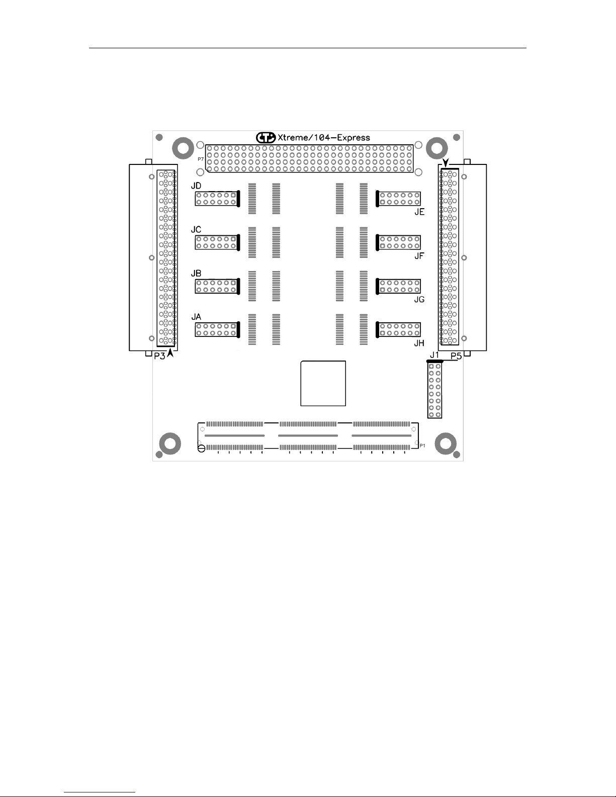
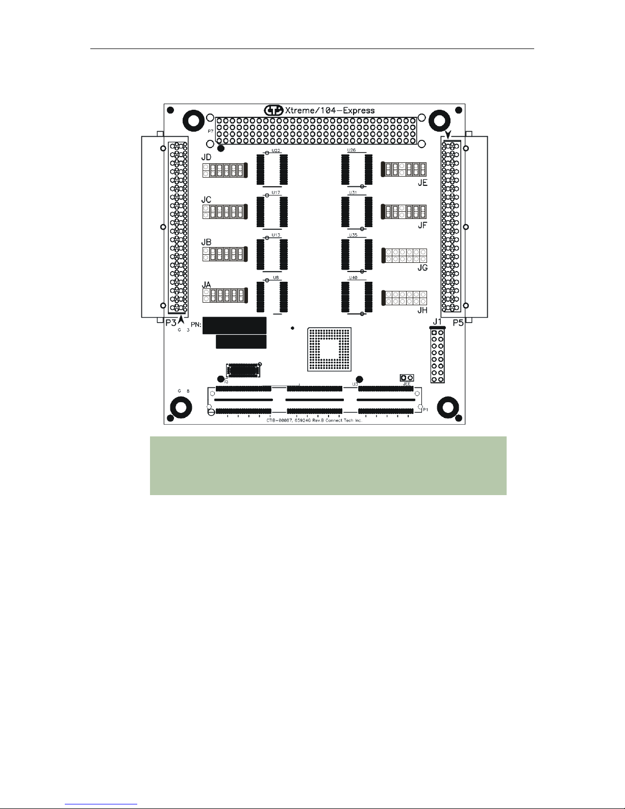
Xtreme/104-Express Board Diagram
Connect Tech Xtreme/104-Express User Manual
Figure 1: Xtreme/104-Express Hardware Components
Revision 0.00
7
Page 8

Connect Tech Xtreme/104-Express User Manual
Xtreme/104-Express Installation Overview
Before you begin, take a moment to ensure your package includes the components that ship with
your product. These components should include:
One Xtreme/104-Express adapter
One CD containing software and documentation
DB-9 male fan-out cables (optional)
If any of these components are missing, contact Connect Tech or your reseller.
There are three stages to installing your Xtreme/104-Express:
1. Hardware Configuration
Interrupts and memory selection will be set by the host computer’s BIOS and operating
system. This section outlines jumper settings and configuration.
2. Hardware Installation
Installation involves the physical installation of the Xtreme/104-Express into your
computer. Please note that you should configure any jumper settings prior to installing
the board.
3. Software/Driver Installation
Load the appropriate driver for your operating system, as found on the accompanying
CD. Installation guides are also available on the CD to aid you in this process.
Hardware Configuration
Interrupts and Memory Address Selection
The Xtreme/104-Express board is a PCI/104-Express card, so the host computer’s BIOS will
automatically set interrupts and memory addresses when you power up the system. Depending
on the operating system you are using, the operating system may opt to re-configure the devices.
Electrical Interfaces
RS-232 Electrical Interface
This is the default setting for the selectable interface of the Xtreme/104-Express. To operate a
port in RS-232 mode, no jumpers are installed on the corresponding jumper block.
RS-422/485 Electrical Interface
Xtreme/104-Express models offer three modes of RS-422/485 communication, as outlined
below. (See Figure 2 to see examples of jumper settings.)
Full Duplex Mode
In this mode, TxD+/- is being driven to a known level all the time. This mode is typically used in
point-to-point situations much like RS-232. It is the default setting for RS-422/485 mode.
Revision 0.00
8
Page 9

Half Duplex Mode
In this mode the TxD+/- line driver is enabled only when data is transmitted and RxD+/- is
disabled when data is being transmitted. This mode is typically used in either point-to-point 2wire connections OR in multi-drop 2-wire bus connections. This mode requires software setup
in Control Panel – System – Hardware – Device Manager – Ports – CTI Xtreme/104 PCI Express UART Serial
Port.
Multi-drop Mode
In this mode the TxD+/- line driver is enabled only when data is transmitted and RxD+/- is
enabled all the time. This mode is typically used in multi-drop 4-wire connections. This mode
requires software setup in Control Panel – System Properties – Hardware – Device Manager – Ports – CTI
Xtreme/104 PCI Express UART Serial Port.
Line Bias/Termination
The RS-422/485 transceivers can be configured to terminate and produce a line level mark
condition on the receiver, and/or terminate the transmitter. These options are enabled through
on-board jumper selectable resistors. These options are typically used in multi-drop 4-wire or
half duplex 2-wire connections.
Jumper Block Settings
The following jumper block diagram depicts typical settings on an interface-selectable
Xtreme/104-Express. (See Figure 1 for location of jumper blocks.)
Connect Tech Xtreme/104-Express User Manual
Figure 2: Jumper Block Diagrams
Jumper Block Summary
RS-485 Selection
TXD Control
RXD Control
RXD +/- Termination/Bias
RXD +/- Termination/Bias
TXD +/- Termination
RS-232 RS-485
Full Duplex
NOTE: You must configure your jumper block settings before installing the
Xtreme/104-Express into your system.
RS-485
Half Duplex
RS-485
Multi-Drop Slave
Revision 0.00
9
Page 10
Connect Tech Xtreme/104-Express User Manual
Figure 3: Example port configuration jumper block settings
NOTE: The example above illustrates the following:
Ports 1, 2, 3 and 4 are configured for RS-485 Half-Duplex
Ports 5 and 6 are configured for RS-485 Multi-Drop Slave
Ports 7 and 8 are configured for RS-232
RS-485 Selection: Install this jumper to configure a port for RS-422/485 mode. If the jumper is
not installed, the port will function in RS-232 mode. All jumpers should be removed from any
port operating in RS-232 mode.
TxD Control: Install this jumper to enable the RS-485 transmitter only when sending data. This
mode is useful for half-duplex operation when only one device is allowed to send data at a time.
If the jumper is not installed, the transmitter will always drive the line to an idle state when not
sending data.
RxD Control: Install this jumper to enable the RS-485 receiver only when NOT transmitting
data. This is useful for half-duplex operation to prevent the transmitting device from receiving
the data it has sent. If this jumper is not installed, the receiver is always enabled and ready to
receive data.
RxD ± Termination/Bias: Install this pair of jumpers to enable a 120 Ohm terminator across the
RxD+ and RxD- pins for the corresponding port. A biasing network is also enabled that drives
the receiver to an inactive or safe mode. The receiver can still receive data from another device
and the biasing helps to prevent the reception of data generated by noise on the transmission
line, or a disconnected line. The two jumpers for RxD termination/bias must be installed and
removed as a pair.
TxD ± Termination: Install this jumper to enable a 120 Ohm resistor across the TxD+ and
TxD- pins of the corresponding port.
Revision 0.00
10
Page 11

Half Duplex and Multi-drop modes require you to select the appropriate mode
via software, appropriate wiring and the proper jumper block settings. Please
refer to the wiring recommendations (Figure 4) and the readme.txt files found in
the appropriate directories on the CD.
Tri-state Operation
Xtreme/104-Express models offer a power-on tri-state option to ensure glitch-free network
operation while the system is powering up. If enabled, the Xtreme/104-Express will tri-state the
transmitter until the driver opens the port. This operation is configurable for any port configured
as RS-485, regardless of the RS-485 mode selected.
Jumper J1 controls the power-on tri-state functionality. Install a jumper on the first location of
the J1 in order to tri-state Port 1 at power-on. Install a jumper on the second position for Port 2,
etc. The ports will not come out of tri-state until the operating system driver begins transmitting
on the associated port.
Installing a jumper on J1 will have no effect on ports configured in RS-232 mode.
Connect Tech Xtreme/104-Express User Manual
Revision 0.00
11
Page 12

Connect Tech Xtreme/104-Express User Manual
Connectors/Pinouts
Table 1: I/O Signal Assignments for Xtreme/104-Express
P3 contains the signals for ports 1-4, and P5 contains the signals for ports 5-8.
Header
Port No.
1 or 5
2 or 6
3 or 7
4 or 8
Pin No. RS-232 Direction RS-
422/485
1 DCD Input RxD+ Input
2 DSR Input CTS- Input
3 RxD Input RxD- Input
4 RTS Output RTS+ Output
5 TxD Output TxD+ Output
6 CTS Input CTS+ Input
7 DTR Output TxD- Output
8 RI Input RTS- Output
9 SG Signal Ground SR Signal Reference
10 N/C No Connection N/C No Connection
11 DCD Input RxD+ Input
12 DSR Input CTS- Input
13 RxD Input RxD- Input
14 RTS Output RTS+ Output
15 TxD Output TxD+ Output
16 CTS Input CTS+ Input
17 DTR Output TxD- Output
18 RI Input RTS- Output
19 SG Signal Ground SR Signal Reference
20 N/C No Connection N/C No Connection
21 DCD Input RxD+ Input
22 DSR Input CTS- Input
23 RxD Input RxD- Input
24 RTS Output RTS+ Output
25 TxD Output TxD+ Output
26 CTS Input CTS+ Input
27 DTR Output TxD- Output
28 RI Input RTS- Output
29 SG Signal Ground SR Signal Reference
30 N/C No Connection N/C No Connection
31 DCD Input RxD+ Input
32 DSR Input CTS- Input
33 RxD Input RxD- Input
34 RTS Output RTS+ Output
35 TxD Output TxD+ Output
36 CTS Input CTS+ Input
37 DTR Output TxD- Output
38 RI Input RTS- Output
39 SG Signal Ground SR Signal Reference
40 N/C No Connection N/C No Connection
Direction
Cable CAG08104 will send signals to eight DB-9 male connectors. See Table 2 for DB-9 pinouts
Revision 0.00
12
Page 13
Connect Tech Xtreme/104-Express User Manual
D
Xtreme/104
-
Express
RTS +
RTS -
CTS +
CTS -
RxD +
RxD -
RxD +
TxD +
RxD -
TxD -
RTS -
CTS -
RTS +
CTS +
SR
SR
Xtreme/104-Express
RS-485/422
RTS +
RTS
-
CTS +
-
TxD +
RxD +
RxD
-
RxD +
-
TxD -
-
-
RTS +
SR
SR
BlueStorm/Express
Opto
RS-422/
485
3
4
2
6
9
7
8
RS-422/485
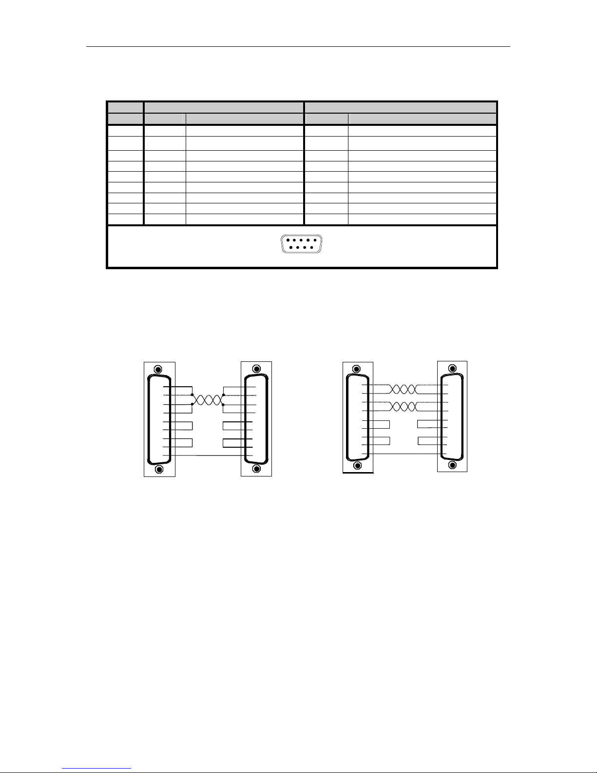
Table 2: DB-9 Male Pinouts
Pin # RS-232 RS-422/485
DB-9 Signal Direction Signal Direction
1 DCD Input RxD+ Input
2 RxD Input
RxD- Input
Adapter
3 TxD Output TxD+ Output
4 DTR Output TxD- Output
5 SG Signal Ground SR Signal Reference
6 DSR Input CTS- Input
7 RTS Output RTS+ Output
8 CTS Input CTS+ Input
9 RI Input RTS- Output
DB-9 Male
1
6
5
9
Figure 4: RS-422/485 Wiring Diagram
Adapter
Peripheral
Adapter
1
TxD +
3
TxD -
4
2
7
8
9
6
5
1
5
TxD -
RxD
RTS
CTS
4 Wire Diagram
Peripheral
TxD +
CTS +
CTS
Revision 0.00
13
Page 14

Connect Tech Xtreme/104-Express User Manual
Hardware Installation
Installing the Xtreme/104-Express into your system
1. Turn off the power to your PCI/104-Express system and open any relevant enclosure to
gain access to the stack (consult your system’s documentation for more information on
this procedure).
2. Mount the Xtreme/104-Express into an available PCI Express slot.
NOTE: Ensure that all PCI/104-Express cards are within 6 cards from the CPU
and are stacked closest to the CPU. PCI/104-Express cards must stack in only
one direction, either on top of or below the CPU, and there must be no more
than six PCI/104-Express cards installed in a given stack without specialized
extender circuitry.
The Xtreme/104-Express provides support for Windows 2000/XP/XP x64/XPe/Server
2003/Server 2003 x64 and Vista. Please refer to the readme.txt files found in the appropriate
directories on the CD containing drivers and documentation. These files contain technical tips
or release notes concerning installation and configuration of the device driver. For further
information concerning software installation of Xtreme/104-Express products please visit the
Connect Tech website at www.connecttech.com.
If you are interested in a device driver for an operating system not listed, please contact the
Connect Tech Sales Department. Also, visit the Download Zone of the Support Center on the
Connect Tech website for the latest product manuals, installation guides, diagnostic utilities and
device driver software.
Revision 0.00
14
Page 15
Software/Driver Installation
Windows Installation
The following instructions outline how to install the Xtreme/104-Express to a computer running
Windows XP. For other operating system installations, consult the readme.txt and Installation
Guides available on the CD shipped with your board(s).
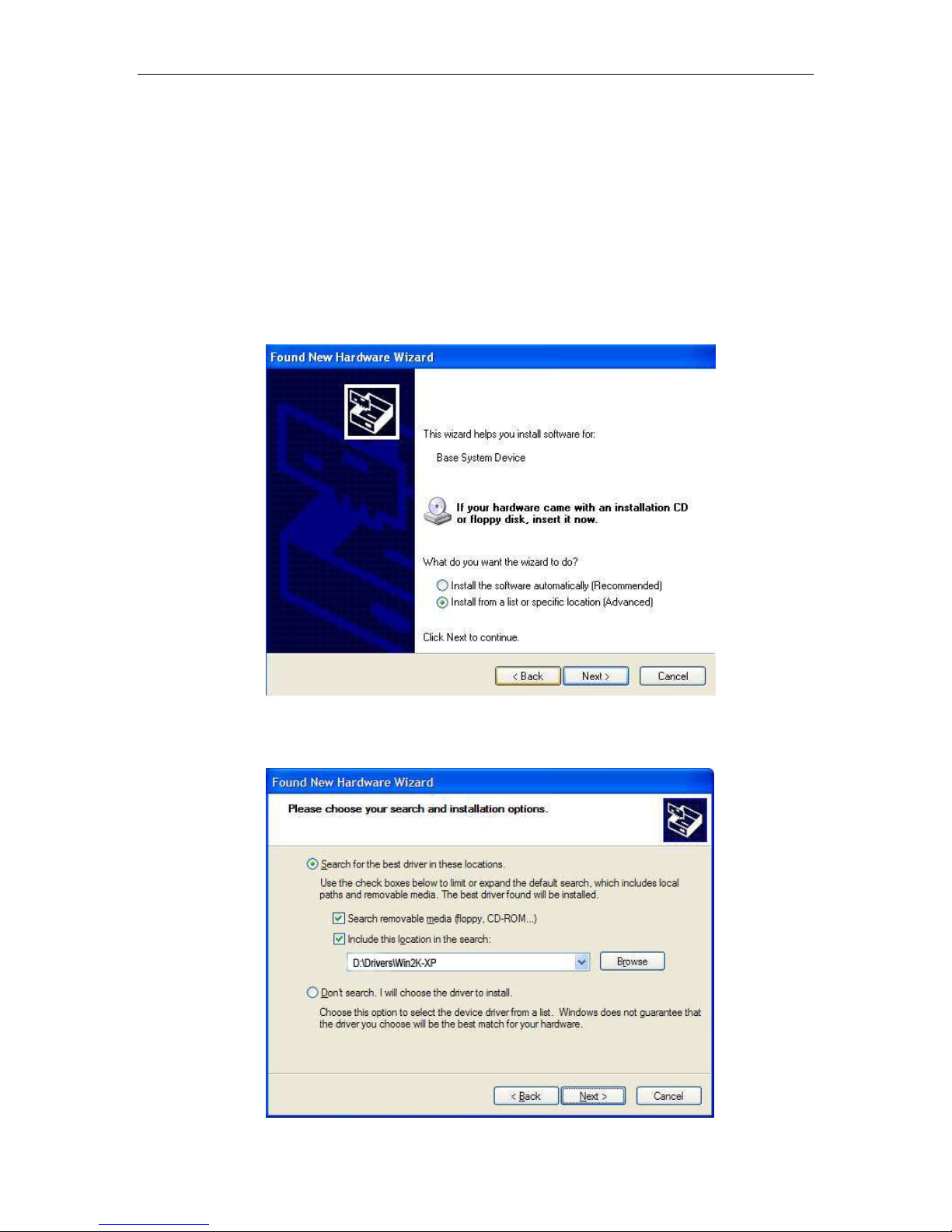
1. After inserting the Xtreme/104-Express into your system’s PCI Express slot, turn on
your system. A Found New Hardware Wizard will appear. Insert the Xtreme/104-Express
CD into your drive as requested. Select Install from a list or specific location (Advanced).
Select Next.
Connect Tech Xtreme/104-Express User Manual
2. Choose Select removable media (floppy, CD-ROM) and Include this location in the search and
type D:\ Drivers\Win2K-XP, where D is the drive letter of your CD ROM. Now select Next.
Revision 0.00
15
Page 16

Connect Tech Xtreme/104-Express User Manual
3. Once you have clicked Next , the Found New Hardware Wizard will begin to install the
software.
4. Next a window will appear indicating that the software for Xtreme/104-Express has not
passed Windows logo testing. Select Continue Anyway.
GPIO Adapter
Revision 0.00
16
Page 17
Connect Tech Xtreme/104-Express User Manual
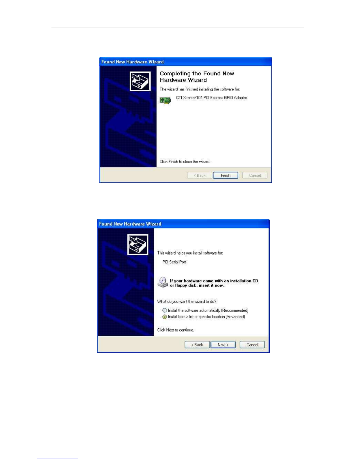
5. CTI Xtreme/104 PCI Express GPIO Adapter installation is complete. Select Finish.
6. Once the software for the CTI Xtreme/104 PCI Express GPIO Adapter has been
installed, a window will appear to begin the installation for the PCI Serial Port. Select
Install from a list or specific location (Advanced). Select Next.
Revision 0.00
17
Page 18
Connect Tech Xtreme/104-Express User Manual
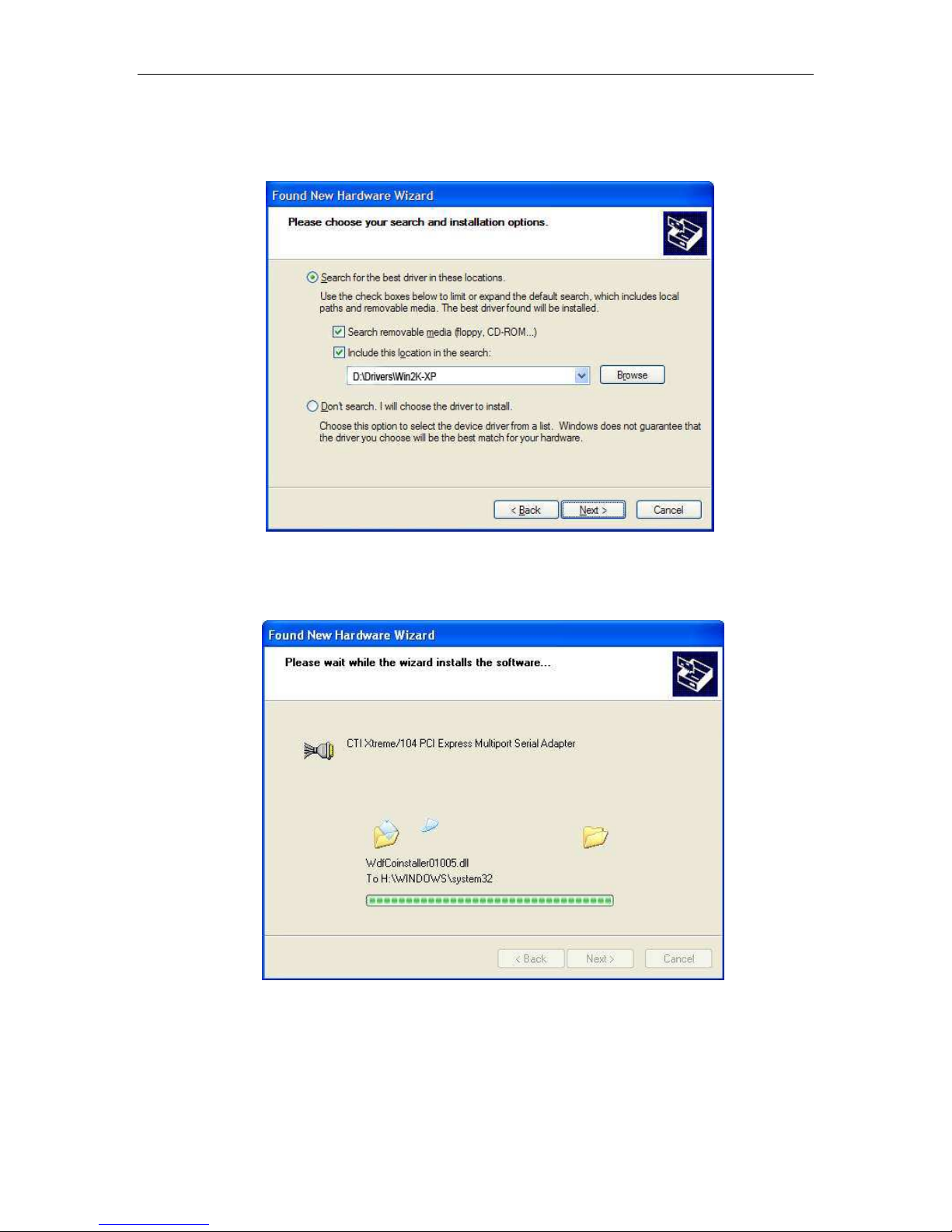
7. Choose Select removable media (floppy, CD-ROM) and Include this location in the search and
type D:\ Drivers\Win2K-XP, where D is the drive letter of your CD ROM. Now select Next.
8. Once you have clicked Next , the Found New Hardware Wizard will begin to install the
software.
Revision 0.00
18
Page 19

Connect Tech Xtreme/104-Express User Manual
9. Next a window will appear indicating that the software for Xtreme/104-Express has not
passed Windows logo testing. Select Continue Anyway.
10. CTI Xtreme/104 PCI Express Multiport Serial Adapter installation is complete. Select
Finish.
Revision 0.00
19
Page 20

Connect Tech Xtreme/104-Express User Manual
11. Once the software for the CTI Xtreme/104 PCI Express Multiport Serial Adapter has
been installed, a window will appear to begin the installation for the Xtreme/104 PCI
Express UART Serial Port. Select Install from a list or specific location (Advanced). Select
Next.
12. Choose Select removable media (floppy, CD-ROM) and Include this location in the search and
type D:\ Drivers\Win2K-XP, where D is the drive letter of your CD ROM. Now select Next.
Revision 0.00
20
Page 21

Connect Tech Xtreme/104-Express User Manual
13. Once you have clicked Next , the Found New Hardware Wizard will begin to install the
software.
14. Next a window will appear indicating that the software for Xtreme/104-Express has not
passed Windows logo testing. Select Continue Anyway.
UART Serial Port
Revision 0.00
21
Page 22

Connect Tech Xtreme/104-Express User Manual
15. CTI Xtreme/104 PCI Express UART Serial Port installation is complete. Select Finish.
16. Verify the presence of the Xteme/104-Express serial ports in your system by going to
Start – Control Panel – System – Hardware – Device Manager. You should see CTI
Xtreme/104 PCI Express GPIO Adapter, Xtreme/104 PCI Express Multiport Serial Adapter,
and Ports.
Revision 0.00
22
Page 23

Connect Tech Xtreme/104-Express User Manual
17. Double click on CTI Xtreme/104 PCI Express GPIO Adapter. Click on the General tab
to see that your device is working properly.
NOTE: The Windows driver provided with your Xtreme/104Express unit has not been signed by Microsoft. If you require
a signed driver, please contact Connect Tech.
Revision 0.00
23
Page 24

Connect Tech Xtreme/104-Express User Manual
Port Settings
You can now access individual port settings such as baud rate, data bits, parity, stop bits and
flow control by choosing the appropriate CTI Xtreme/104 PCI Express UART Serial Port under
Settings in the Device Manager.
COM Port Number
The driver supports the ability to change COM port names, which is also referred to as COM
port mapping. For example specifying COM5 would set the COM name for the port selected to
COM5.
NOTE: Ensure the COM name selected is not already in use
or the port may not respond properly.
Revision 0.00
24
Page 25

Connect Tech Xtreme/104-Express User Manual
FIFOs
Choosing the FIFOs tab, located at Start – Control Panel – System – Hardware – Device Manager Ports will allow you to select the settings for the FIFO buffers.
Receive and Transmit FIFO Settings
These sliders adjust the size of UART FIFO levels used by the CTI Xtreme/104 PCI Express
UART serial ports. You obtain more buffering the further you move the slider to the right. This
results in higher throughput and lower load on the system. Note that high buffer levels can cause
communication problems with some applications.
Revision 0.00
25
Page 26

Connect Tech Xtreme/104-Express User Manual
Specifications
Operating Environment
● Storage temperature: -40° C to 105° C
● Operating temperature: -40° C to 85° C
● Relative humidity: 95% non-condensing
Communications
Baud Rates
UARTs
● Air movement: no requirement
● RS-232: up to 1.000 Mbps
● RS-422/485: up to 15.625 Mbps
Custom baud rates are also available. The onboard fractional baud rate divisor will
match almost any custom baud rate..
● One octal PCI Express UART with up to 128 byte transmit and receive FIFO
buffers
Dimensions
Fully PCI/104-Express compliant
● Length: 9.017 cm, 3.550 inches
● Height: 9.5885 cm, 3.775 inches
Revision 0.00
26
 Loading...