

Page 1
Orbitty Carrier for Jetson™ TX1
Users Guide
Connect Tech Inc. Tel: 519-836-1291
42 Arrow Road Toll: 800-426-8979 (North America only)
Guelph, Ontario Fax: 519-836-4878
N1K 1S6 Email: sales@connecttech.com
www.connecttech.com support@connecttech.com
CTIM-00471 Revision 0.05 2016/12/01
Page 2

Orbitty Carrier for Jetson™ TX1
Users Guide
www.connecttech.com
Document: CTIM-00471
Revision: 0.05
Page 2 of 27
Connect Tech Inc. 800-426-8979 | 519-836-1291
Date: 2016/12/01
Table of Contents
Table of Contents ................................................................................................................................... 2
Preface ................................................................................................................................................... 4
Disclaimer ....................................................................................................................................................... 4
Customer Support Overview ........................................................................................................................... 4
Contact Information ........................................................................................................................................ 4
Limited Product Warranty ............................................................................................................................... 5
Copyright Notice ............................................................................................................................................. 5
Trademark Acknowledgment .......................................................................................................................... 5
ESD Warning .................................................................................................................................................. 6
Revision History .................................................................................................................................... 6
Introduction........................................................................................................................................... 7
Product Features and Specifications ...................................................................................................... 7
Product Overview .................................................................................................................................. 8
Block Diagram ................................................................................................................................................ 8
Connector Locations (Top Side) ..................................................................................................................... 8
Connector Summary ........................................................................................................................................ 9
Switch Summary & Locations ........................................................................................................................ 9
Detailed Feature Description ................................................................................................................ 10
Jetson™ TX1 Board-to-Board Connector ................................................................................................ ..... 10
System Expansion IO Connector................................................................................................................... 11
System Expansion IO Connector – Detailed Signal Descriptions ...................................................... 12
HDMI Connector ........................................................................................................................................... 13
10/100/1000 Ethernet (GBE) ......................................................................................................................... 14
USB 3.0 ......................................................................................................................................................... 15
USB OTG ...................................................................................................................................................... 16
USB OTG – Host Mode ..................................................................................................................... 16
USB OTG – Client Mode (Used for Image Flashing) ........................................................................ 16
Input Power ................................................................................................................................................... 17
Input Power - Wiring .......................................................................................................................... 17
Switch Details ...................................................................................................................................... 18
DIP Switch Details (S1) ................................................................................................................................ 18
S1 Usage Examples ............................................................................................................................ 18
Push Button Details (SW1, SW2, SW3)................................................................................................ ........ 19
Typical Installation .............................................................................................................................. 20
Power Supply ....................................................................................................................................... 21
On-Board Indicator LED’s .................................................................................................................. 21
Current Consumption Details .............................................................................................................. 22
Software / BSP Details ......................................................................................................................... 23
NVIDIA Linux For Tegra (L4T) ................................................................................................................... 23
NVIDIA Jetpack for L4T .............................................................................................................................. 23
Connect Tech’s Custom L4T BSP (CTI-L4T) .............................................................................................. 23
Force Recovery Mode ................................................................................................................................... 24
Page 3

Orbitty Carrier for Jetson™ TX1
Users Guide
www.connecttech.com
Document: CTIM-00471
Revision: 0.05
Page 3 of 27
Connect Tech Inc. 800-426-8979 | 519-836-1291
Date: 2016/12/01
Thermal Details ................................................................................................................................... 25
Mechanical Details ............................................................................................................................... 26
3D STEP Model ............................................................................................................................................ 26
2D Dimensions Drawing ............................................................................................................................... 26
Stack-up Drawing .......................................................................................................................................... 27
Cables .................................................................................................................................................. 27
Page 4

Orbitty Carrier for Jetson™ TX1
Users Guide
www.connecttech.com
Document: CTIM-00471
Revision: 0.05
Page 4 of 27
Connect Tech Inc. 800-426-8979 | 519-836-1291
Date: 2016/12/01
Preface
Disclaimer
The information contained within this user’s guide, including but not limited to any product specification, is
subject to change without notice.
Connect Tech assumes no liability for any damages incurred directly or indirectly from any technical or
typographical errors or omissions contained herein or for discrepancies between the product and the user’s
guide.
Customer Support Overview
If you experience difficulties after reading the manual and/or using the product, contact the Connect Tech
reseller from which you purchased the product. In most cases the reseller can help you with product installation
and difficulties.
In the event that the reseller is unable to resolve your problem, our highly qualified support staff can assist you.
Our support section is available 24 hours a day, 7 days a week on our website at:
www.connecttech.com/sub/support/support.asp. See the contact information section below for more
information on how to contact us directly. Our technical support is always free.
Contact Information
Mail/Courier
Connect Tech Inc.
Technical Support
42 Arrow Road
Guelph, Ontario
Canada N1K 1S6
Email/Internet
sales@connecttech.com
support@connecttech.com
www.connecttech.com
Note:
Please go to the Download Zone or the Knowledge Database in the Support Center on the Connect Tech
website for product manuals, installation guides, device driver software and technical tips.
Submit your technical support questions to our customer support engineers via the Support Center on the
Connect Tech website.
Telephone/Facsimile
Technical Support representatives are ready to answer your call Monday through Friday, from 8:30 a.m. to
5:00 p.m. Eastern Standard Time. Our numbers for calls are:
Toll Free: 800-426-8979 (North America only)
Telephone: 519-836-1291 (Live assistance available 8:30 a.m. to 5:00 p.m. EST, Monday to Friday)
Facsimile: 519-836-4878 (on-line 24 hours)
Page 5

Orbitty Carrier for Jetson™ TX1
Users Guide
www.connecttech.com
Document: CTIM-00471
Revision: 0.05
Page 5 of 27
Connect Tech Inc. 800-426-8979 | 519-836-1291
Date: 2016/12/01
Limited Product Warranty
Connect Tech Inc. provides a one year Warranty for the Orbitty Carrier. Should this product, in Connect Tech
Inc.'s opinion, fail to be in good working order during the warranty period, Connect Tech Inc. will, at its
option, repair or replace this product at no charge, provided that the product has not been subjected to abuse,
misuse, accident, disaster or non-Connect Tech Inc. authorized modification or repair.
You may obtain warranty service by delivering this product to an authorized Connect Tech Inc. business
partner or to Connect Tech Inc. along with proof of purchase. Product returned to Connect Tech Inc. must be
pre-authorized by Connect Tech Inc. with an RMA (Return Material Authorization) number marked on the
outside of the package and sent prepaid, insured and packaged for safe shipment. Connect Tech Inc. will
return this product by prepaid ground shipment service.
The Connect Tech Inc. Limited Warranty is only valid over the serviceable life of the product. This is defined
as the period during which all components are available. Should the product prove to be irreparable, Connect
Tech Inc. reserves the right to substitute an equivalent product if available or to retract the Warranty if no
replacement is available.
The above warranty is the only warranty authorized by Connect Tech Inc. Under no circumstances will
Connect Tech Inc. be liable in any way for any damages, including any lost profits, lost savings or other
incidental or consequential damages arising out of the use of, or inability to use, such product.
Copyright Notice
The information contained in this document is subject to change without notice. Connect Tech Inc. shall not
be liable for errors contained herein or for incidental consequential damages in connection with the furnishing,
performance, or use of this material. This document contains proprietary information that is protected by
copyright. All rights are reserved. No part of this document may be photocopied, reproduced, or translated to
another language without the prior written consent of Connect Tech, Inc.
Copyright 2016 by Connect Tech, Inc.
Trademark Acknowledgment
Connect Tech, Inc. acknowledges all trademarks, registered trademarks and/or copyrights referred to in this
document as the property of their respective owners. Not listing all possible trademarks or copyright
acknowledgments does not constitute a lack of acknowledgment to the rightful owners of the trademarks and
copyrights mentioned in this document.
Page 6
Orbitty Carrier for Jetson™ TX1
Users Guide
www.connecttech.com
Document: CTIM-00471
Revision: 0.05
Page 6 of 27
Connect Tech Inc. 800-426-8979 | 519-836-1291
Date: 2016/12/01
ESD Warning
Electronic components and circuits are sensitive to
ElectroStatic Discharge (ESD). When handling any circuit
board assemblies including Connect Tech carrier
assemblies, it is recommended that ESD safety
precautions be observed. ESD safe best practices include,
but are not limited to:
Leaving circuit boards in their antistatic packaging
until they are ready to be installed.
Using a grounded wrist strap when handling circuit
boards, at a minimum you should touch a grounded
metal object to dissipate any static charge that may be
present on you.
Only handling circuit boards in ESD safe areas, which
may include ESD floor and table mats, wrist strap
stations and ESD safe lab coats.
Avoiding handling circuit boards in carpeted areas.
Try to handle the board by the edges, avoiding contact
with components.
Revision History
Revision
Date
Changes
0.00
2016/04/28
Preliminary Release
0.01
2016/06/13
First Production Release
0.02
2016/08/10
Fixed BSP Download Link
0.03
2016/11/04
Updated images and assembly drawing
0.04
2016/11/24
Added note on power supply, MSG064
0.05
2016/12/01
Added Power Requirements and update maximum input voltage
Page 7

Orbitty Carrier for Jetson™ TX1
Users Guide
www.connecttech.com
Document: CTIM-00471
Revision: 0.05
Page 7 of 27
Connect Tech Inc. 800-426-8979 | 519-836-1291
Date: 2016/12/01
Introduction
Connect Tech’s Orbitty Carrier for NVIDIA® Jetson™ TX1 brings a low cost deployable Jetson™ TX1 Solution to
the market. Designed to match the NVIDIA® Jetson™ TX1 module form factor, the Orbitty’s design includes
Gigabit Ethernet, HDMI Video, USB 3.0, USB 2.0 (w/ OTG functionality), 2 x UART ports and 4-bits of GPIO.
Product Features and Specifications
Feature
Orbitty Carrier for NVIDIA Jetson TX1
Module Compatibility
NVIDIA Jetson TX1
- Datasheet Downloads: Module Datasheet - SoC Datasheet
Mechanical Dimensions
X/Y Footprint: 87mm x 50mm
- Tallest Component Height: 13.42mm (From Top PCB Surface of Orbitty)
- Total Stack Height: 30.18mm (Orbitty + TX1 Module + TX1 Flat Heatplate)
- 3D STEP Model: Download Here
Video Output
1x HDMI 2.0
- Maximum: 6Gbps, 24bpp, 4096x2160@60Hz
Ethernet
1x Gigabit Ethernet
- 10/100/1000 BASE-T
USB
1x USB 3.0 (5Gbps, 1A Maximum Current Sourcing)
1x USB 2.0 (w/ OTG functionality)
Audio Output
HDMI Integrated
UART
2x 3.3V UART Ports
- TX/RX lines only
GPIO
4-bits GPIO
- 3.3V CMOS Level
- Configurable as inputs or outputs
SD Card
1x microSD Card Slot
- 4-bit Data
- Support for SD 4.0 Specification without UHS-II
Video Inputs
Video Inputs can be accessed through any of the of the following interfaces:
- USB 3.0 / 2.0
- Gigabit Ethernet
I2C
1x I2C (Master Controller)
- Pullup Level: 1k ohm
- Operation Speeds: 100kbit/s, 400kbit/s, 1Mbit/s, 3.4Mbit/s
Misc Interfaces
User Power Output Pins: +3.3V and +5V
Fan Connection: 4-pin, +5V, PWM Capability
On-board and External Button Interfaces: Reset, Power, Recovery
External RTC Battery Connection
Power Requirements
Input Voltage Range: +9V to +15V DC
TX1 Module Consumption: 6.5W to 15W (dependent on CPU/GPU utilization)
Orbitty Carrier Consumption: 2W to 6W (dependent on draw of peripheral ports)
Temperature
TX1 Module Operating Temperature Range: -25C to +80C
TX1 SoC Junction Temperature Range: -25C to +105C
Orbitty Carrier Operating Temperature Range: -40C to +85C
Weight
34g
Warranty and Support
1 Year Warranty and Free Support
Page 8
Orbitty Carrier for Jetson™ TX1
Users Guide
www.connecttech.com
Document: CTIM-00471
Revision: 0.05
Page 8 of 27
Connect Tech Inc. 800-426-8979 | 519-836-1291
Date: 2016/12/01
Product Overview
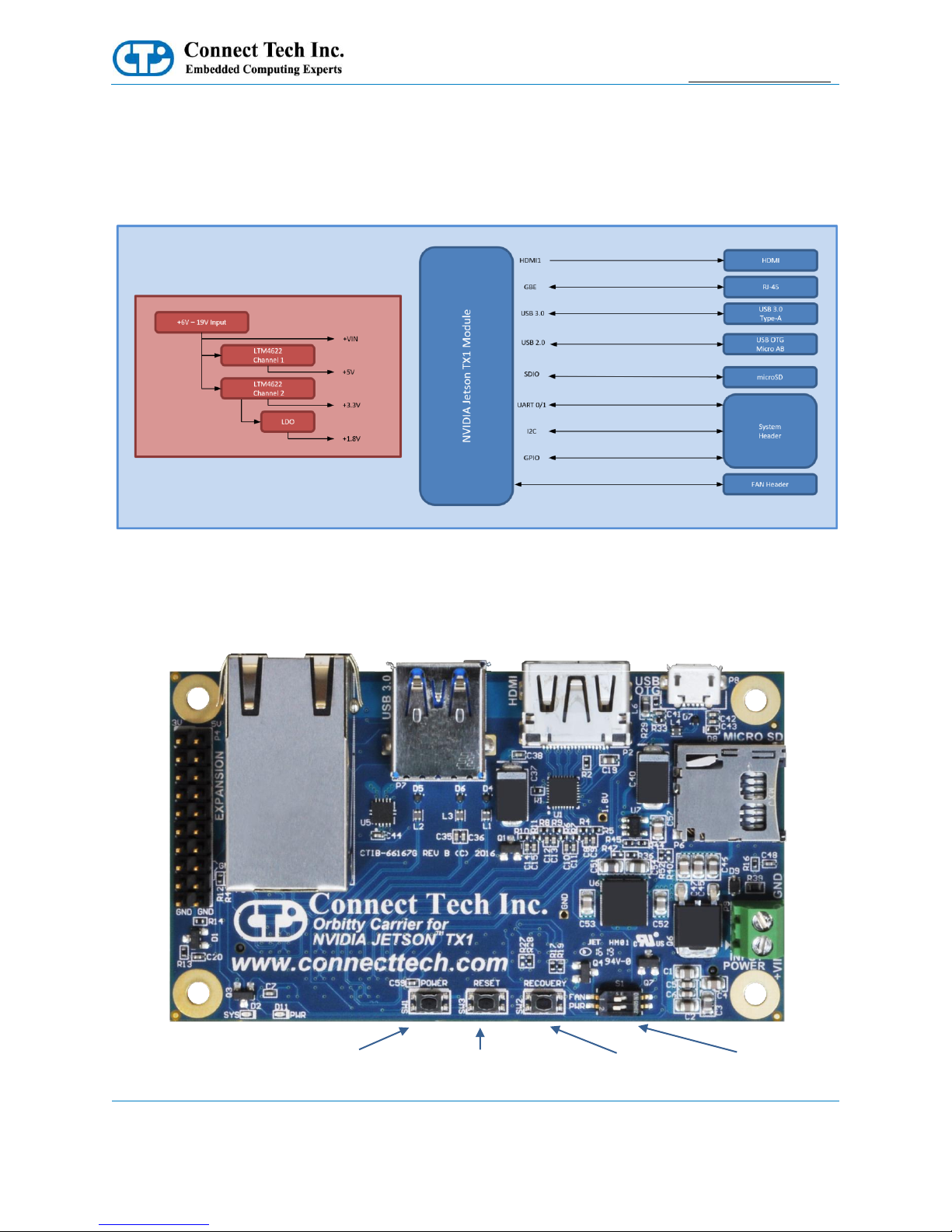
Block Diagram
Connector Locations (Top Side)
FAN / SYS PWR
SWITCH (S1)
POWER
BUTTON (SW1)
RESET
BUTTON (SW3)
RECOVERY
BUTTON (SW2)
POWER
INPUT (P9)
MICRO SD (P6)
SYS LED
PWR LED
Gigabit Ethernet (P6)
USB 3.0 (P7)
USB OTG (P8)
HDMI (P2)
EXPANSION IO
HEADER (P4)
Page 9

Orbitty Carrier for Jetson™ TX1
Users Guide
www.connecttech.com
Document: CTIM-00471
Revision: 0.05
Page 9 of 27
Connect Tech Inc. 800-426-8979 | 519-836-1291
Date: 2016/12/01
Connector Summary
Designator
Connector
Description
P1
TX1 Module Connector
NVIDIA Jetson TX1 Module Board-to-Board Connector
P2
HDMI
HDMI 2.0 Maximum: 6Gbps, 24bpp, 4096x2160@60Hz
P4
Expansion IO Header
Expansion IO Header Interfacing to all Misc IO
P5
Gigabit Ethernet
Gigabit Ethernet 10/100/1000 BASE-T Connection
P6
Micro SD Card Slot
Micro SD Card Slot (4-bit Data, Support for SD 4.0)
P7
USB 3.0
USB 3.0 Type-A Host Connection
P8
USB OTG
USB OTG (Host Mode and Client Mode capable)
P9
Power Input
DC Power Input (+9V to +15V)
Switch Summary & Locations
Designator
Function
Description
S1
Fan / Power Control
Power Start-up Control, FAN PWM / Always ON Control
SW1
Power Button
Power Button, Press to Power ON or OFF
SW2
Reset Button
Reset Button, Press to initiate Reset Sequence
SW3
Recovery
Use to initiate a recovery mode, and flash new image via USB
OTG
Page 10

Orbitty Carrier for Jetson™ TX1
Users Guide
www.connecttech.com
Document: CTIM-00471
Revision: 0.05
Page 10 of 27
Connect Tech Inc. 800-426-8979 | 519-836-1291
Date: 2016/12/01
Detailed Feature Description
Jetson™ TX1 Board-to-Board Connector
With the NVIDIA Jetson™ TX1, the processor and chipset are implemented on the Jetson™ TX1 Module.
This connects to the Orbitty Carrier via a Samtec SEARAY™ Board to Board Connector.
Function
NVIDIA Jetson™ TX1 Interface
Location
P1
Type
Samtec SEARAY™ Connector
Carrier
Connector
Part Number: SEAM-50-03.5-S-08-2-A-K
Manufacturer: Samtec
Mating
Connector
Part Number: SEAF-50-05-S-08-02-A-K
Manufacturer: Samtec
Pinout
Refer to NVIDIA’s Jetson™ TX1 System-on-Module
datasheet for pinout details
Board-toBoard
Standoff
Height
8.0mm height M3 Standoffs Required between
NVIDIA Jetson TX1 Module and Orbitty (ASG003)
Carrier
Page 11

Orbitty Carrier for Jetson™ TX1
Users Guide
www.connecttech.com
Document: CTIM-00471
Revision: 0.05
Page 11 of 27
Connect Tech Inc. 800-426-8979 | 519-836-1291
Date: 2016/12/01
System Expansion IO Connector
The System Expansion header has numerous interfaces to connect external peripherals and IO. As well as the
ability to provide external connection to the Recovery, Reset and Power Buttons. The System Expansion IO
Connector also has 2 voltage output pins to allow powering of external devices.
Function
System Connector
Location
P4
Type
0.1” / 2.54mm Pitch IDC Header (DIL)
Carrier
Connector
Part Number: TSW-110-07-L-D
Manufacturer: Samtec
Mating
Connector
Any IDC / DIC 0.1” Cable, Socket or Jumper Wire
Assemblies
Cable
CBG116
Pinout
Pin
Description
Pin
Description
1
+3.3V OUTPUT
2
+5V OUTPUT
3
UART0 TX
4
UART0 RX
5
UART1 TX
6
UART1 RX
7
GPIO-0
8
GPIO-1
9
GPIO-2
10
GPIO-3
11
I2C CLK
12
I2C SDA
13
RECOVERY
14
RTC BAT INPUT
15
RESET
16
GND
17
POWER BUTTON
18
GND
19
GND
20
GND
Page 12

Orbitty Carrier for Jetson™ TX1
Users Guide
www.connecttech.com
Document: CTIM-00471
Revision: 0.05
Page 12 of 27
Connect Tech Inc. 800-426-8979 | 519-836-1291
Date: 2016/12/01
System Expansion IO Connector – Detailed Signal Descriptions
Signal Name
Description
Type
Pin
Number(s)
+3.3V OUTPUT
+3.3V Power Output Pin
- Max output should be limited to 1A
- Please note there is no external fuse.
Output
1
+5V OUTPUT
+5V Power Output Pin
- Max output should be limited to 1A
- Please note there is no external fuse.
Output
2
UART0 TX
UART 0 Transmit Pin
- This signal is the UART port 0 output from the
TX1 Module
- This is level shifted on the Orbitty carrier to
support 3.3V logic.
- Under L4T this port will show up as /dev/ttyS0
Output
3.3V CMOS
3
UART0 RX
UART 0 Receive Pin
- This signal is the UART channel 0 input on TX1
Module
- This is level shifted on the Orbitty carrier to
support 3.3V logic.
- Under L4T this port will show up as /dev/ttyS0
Input
3.3V CMOS
4
UART1 TX
UART 1 Transmit Pin
- This signal is the UART channel 1 output from
the TX1 Module
- This is level shifted on the Orbitty carrier to
support 3.3V logic.
- Under L4T this port will show up as
/dev/ttyTHS2
Output
3.3V CMOS
5
UART1 RX
UART 1 Receive Pin
- This signal is the UART channel 1 input on TX1
Module
- This is level shifted on the Orbitty carrier to
support 3.3V logic.
- Under L4T this port will show up as
/dev/ttyTHS2
Input
3.3V CMOS
6
GPIO-[0:3]
GPIO Bits 0 to 3
- This signal is the GPIO Bit 0 and can be
configured as an Input or an Output
- This is level shifted on the Orbitty carrier to
support 3.3V logic.
- GPIO-0 = sysfs GPIO 187
- GPIO-1 = sysfs GPIO 186
- GPIO-2 = sysfs GPIO 89
- GPIO-3 = sysfs GPIO 202
Input/Output
Configurable
3.3V CMOS
7,8,9,10
I2C CLK
I2C Clock Signal
- This is clock signal on the I2C bus
- This signal has a pull up on the TX1 module to
+3.3V
- Under L4T this is I2C bus # 1
Output
+3.3V
Open Drain
11
I2C SDA
I2C Data Signal
- This is data signal on the I2C bus
- This signal has a pull up on the TX1 module to
+3.3V
Bidirectional
+3.3V
Open Drain
12
Page 13
Orbitty Carrier for Jetson™ TX1
Users Guide
www.connecttech.com
Document: CTIM-00471
Revision: 0.05
Page 13 of 27
Connect Tech Inc. 800-426-8979 | 519-836-1291
Date: 2016/12/01
- Under L4T this is I2C bus # 1
RECOVERY
System Recovery Pin
- Shorting this signal to Ground will initialize a
system recovery procedure
Input
13
RTC BAT INPUT
RTC Battery Input
- Use this pin to connect a backup battery source
(Coin Cell or other) to sustain the RTC clock on
the TX1 module.
- The voltage should be provided from a 3V
source
Input
14
RESET
External Reset Button Source
- Pulse / Short this signal to GND to initiate a
reset sequence
Input
15
POWER BUTTON
External Power Button Source
- Pulse / Short this signal to GND to initiate a
power sequence
Input
17
GND
Ground / Reference Connection
- This pin is connected to the Orbitty Carrier’s
main digital ground connection
- Use this pin as a reference/return for any
externally connected peripherals to the
Expansion IO Connector
Reference
16,18,19,20
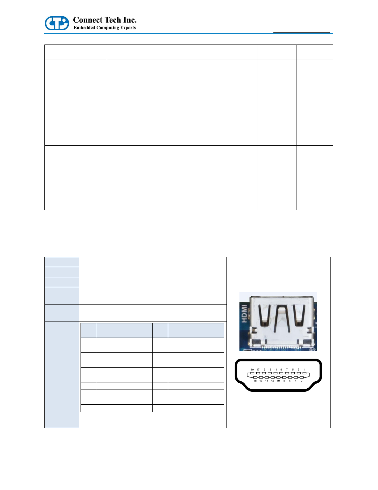
HDMI Connector
Function
HDMI Connector
Location
P2
Type
HDMI Type-A Connector (Female)
Carrier
Connector
Part Number: A35071TR-ND
Manufacturer: TE Connectivity
Mating
Connector
Any HDMI Type-A Cable Assembly
Pinout
Pin Description
Pin Description
1
TMDS Data2+
2
TMDS Data2 GND
3
TMDS Data2-
4
TMDS Data1+
5
TMDS Data1 GND
6
TMDS Data1-
7
TMDS Data0+
8
TMDS Data0 GND
9
TMDS Data0-
10
TMDS Clock+
11
TMDS Clock GND
12
TMDS Clock-
13
CEC
14
No Connect
15
DDC clock
16
DDC data
17
DDC GND
18
+5V Power
19
Hot Plug Detect
Page 14

Orbitty Carrier for Jetson™ TX1
Users Guide
www.connecttech.com
Document: CTIM-00471
Revision: 0.05
Page 14 of 27
Connect Tech Inc. 800-426-8979 | 519-836-1291
Date: 2016/12/01
NVIDIA Jetson TX1 Fan
Function
NVIDIA Jetson TX1 Fan Control
Location
P4
Type
Molex PicoBlade Header
Carrier
Connector
Part Number: 53261-0471
Manufacturer: Molex
Mating
Connector
Part Number: 51021-0400
Manufacturer: Molex
Pinout
Pin
Description 1 GND
2
+5V
3
TACH
4
PWM
NOTE: Please note that Fan PWM (speed control) is NOT natively supported by the stock L4T builds.
If users wish to use the native builds you must enable the S1 DIP Switch to put the Fan into the Always ON
mode.
To enable PWM functionality (speed control) users must deploy CTI-L4T BSP and enable the S1 DIP Switch
to put the Fan into the PWM Enabled mode.
10/100/1000 Ethernet (GBE)
Function
Gigabit Ethernet Connector
Location
P5
Type
RJ-45 8p8c
Carrier
Connector
Part Number: 1RJMG14-220LNL
Manufacturer: Unicom
Mating
Connector
Any RJ-45 Plug with Cat5, Cat5e, Cat6 Type Cabling
Pinout
Pin
Description
Pin
Description
1
TP0+
2
TP0-
3
TP1+
4
TP2+
5
TP2-
6
TP1-
7
TP3+
8
TP3-
Page 15

Orbitty Carrier for Jetson™ TX1
Users Guide
www.connecttech.com
Document: CTIM-00471
Revision: 0.05
Page 15 of 27
Connect Tech Inc. 800-426-8979 | 519-836-1291
Date: 2016/12/01
microSD Card Slot
Function
microSD Card Slot
Location
P7
Type
Molex microSD Memory Card Connector
Carrier
Connector
502570-0893
Pinout
Pin
Description
Pin
Description
1
SDIO_DATA2
2
SDIO_DATA3
3
SDIO_CMD
4
SDIO_VCC
5
SDIO_CLK
6
GND
7
SDIO_DATA0
8
SDIO_DATA1
9
GND
10
SDIO_CD
USB 3.0
The Orbitty Carrier provides one external USB 3.0 Port with an integrated USB 2.0 Port. The USB 3.0 signals
are sourced directly from the Jetson TX1 Module. Over current protection, power supply filtering and ESD
protection is provided on-board. The current limit on this port is set to 1A, if more current capacity is required
please contact sales@connecttech.com
Function
USB 3.0
Location
P7
Type
USB 3.0 Type-A
Carrier
Connector
Part Number: 1932258-1
Manufacturer: TE Connectivity
Mating
Connector
Any USB 3.0 Type-A Cable
Pinout
Pin
Description
Pin
Description
1
VBUS
2
USB 2.0 D-
3
USB 2.0 D+
4
GND
5
SSRX-
6
SSRX+
7
GND
8
SSTX-
9
SSTX+
Page 16
Orbitty Carrier for Jetson™ TX1
Users Guide
www.connecttech.com
Document: CTIM-00471
Revision: 0.05
Page 16 of 27
Connect Tech Inc. 800-426-8979 | 519-836-1291
Date: 2016/12/01
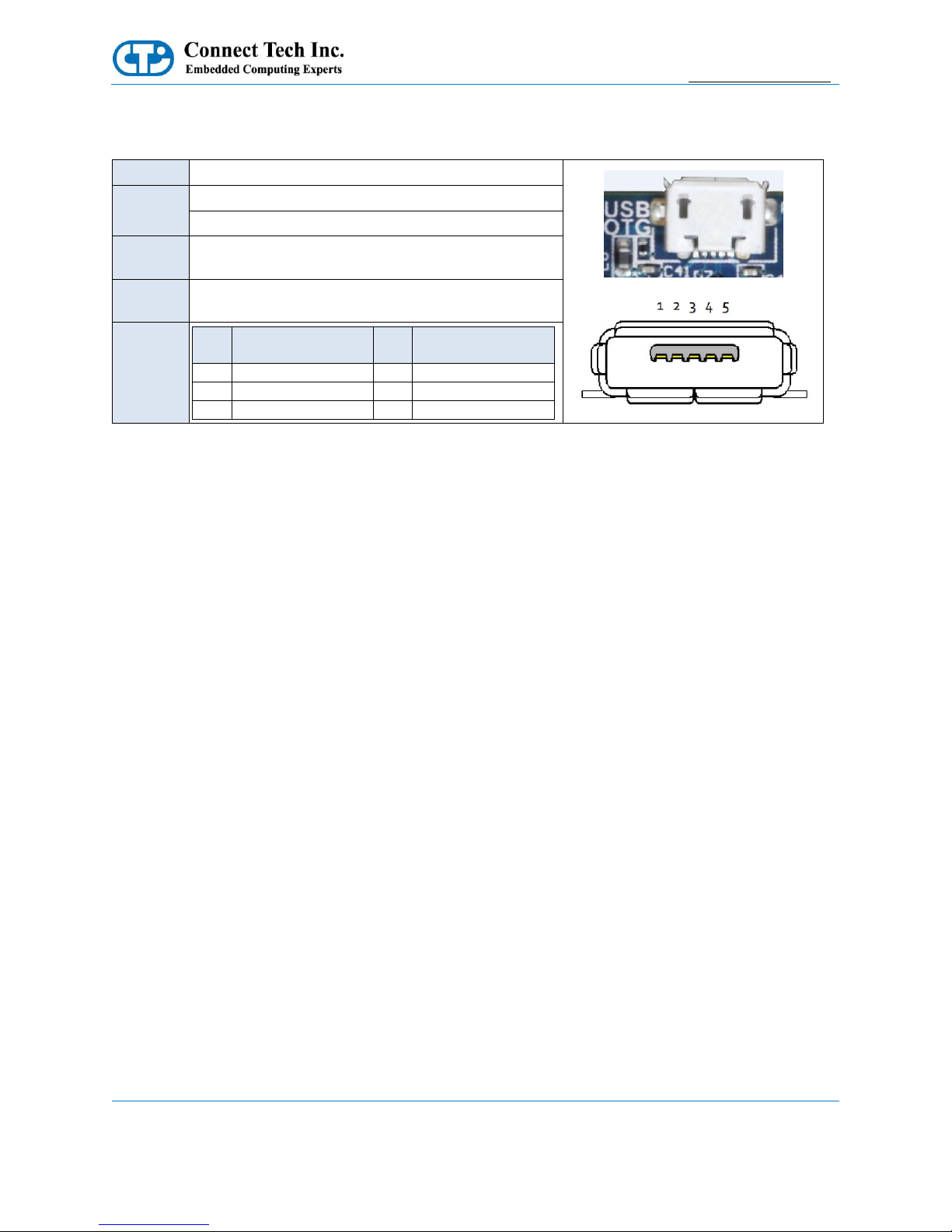
USB OTG
Function
USB OTG
Location
P8
Type
USB 2.0 Micro-AB
Carrier
Connector
Part Number: 47589-0001
Manufacturer: Molex
Mating
Connector
Any USB 2.0 Micro A or Micro B or Cable
Pinout
Pin Description
Pin Description
1
VBUS
2
USB 2.0 D-
3
USB 2.0 D+
4
USB ID
5
GND
USB OTG – Host Mode
To put the USB OTG port into HOST mode, the USB ID pin needs to be left floating. Most USB Micro-A to TypeA (Female) cables will do this internally.
USB OTG – Client Mode (Used for Image Flashing)
To put the USB OTG port into CLIENT mode, the USB ID pin needs to be tied to GND. Most USB Micro-B cables
will do this internally. Once in Client mode this port can then be connected to a Host PC. This is required for
software image flashing. Please see the Software Section of this manual for more details.
Page 17

Orbitty Carrier for Jetson™ TX1
Users Guide
www.connecttech.com
Document: CTIM-00471
Revision: 0.05
Page 17 of 27
Connect Tech Inc. 800-426-8979 | 519-836-1291
Date: 2016/12/01
Input Power
The Orbitty Carrier accepts a single power input to power all on-board devices.
A power input range of +9V to +15V is recommended.
Function
Input Power
Location
P9
Type
3.5mm Pitch Wire-to-Board Screw Terminal
P/N
TBD
Mating
N/A – Any Stripped and Tinned 8-22 AWG Wire
Cable
N/A
Pinout
Pin
Description
1
+VIN
2
GND
Input Power - Wiring
The positive wire should be connected to the +VIN terminal, and the negative wire should be connected to the GND
terminal.
Page 18

Orbitty Carrier for Jetson™ TX1
Users Guide
www.connecttech.com
Document: CTIM-00471
Revision: 0.05
Page 18 of 27
Connect Tech Inc. 800-426-8979 | 519-836-1291
Date: 2016/12/01
Switch Details
DIP Switch Details (S1)
The Orbitty Carrier has a 2 position DIP switch block which controls the PWM Fan Control and the main
Power-up / Start-up Control.
Position No. Position Description Switch ON Switch OFF
1 PWM Fan Control FAN PWM Enabled (SW Controlled) FAN Always ON
2 Power-Up / Start-up Control "AT Mode" - Automatic Start-up Enabled "ATX Mode" - Power Button Press Required
S1 Usage Examples
Page 19

Orbitty Carrier for Jetson™ TX1
Users Guide
www.connecttech.com
Document: CTIM-00471
Revision: 0.05
Page 19 of 27
Connect Tech Inc. 800-426-8979 | 519-836-1291
Date: 2016/12/01
Push Button Details (SW1, SW2, SW3)
The Orbitty Carrier has a 3 tactile push buttons - Power (SW1), RESET (SW3) and RECOVERY (SW2).
Switch Designator
Description
SW1
Power Button
- When Orbitty is in “ATX Mode” a button press will initiate boot-up
sequence
- When Orbitty is ON, a button press will initiate a power down sequence
in the Operating System
- When Orbitty is ON and button is held for 5 seconds the system will do a
hard power off (power down ungracefully)
SW3
Reset Button
- When button is pressed the system will initiate a Reset sequence
SW2
Recovery Button
- Use this button to perform the Force Recovery Procedure detailed in the
Software Section of this manual.
- This is required when flashing a new image onto the TX1 module via the
USB OTB port.
Page 20
Orbitty Carrier for Jetson™ TX1
Users Guide
www.connecttech.com
Document: CTIM-00471
Revision: 0.05
Page 20 of 27
Connect Tech Inc. 800-426-8979 | 519-836-1291
Date: 2016/12/01
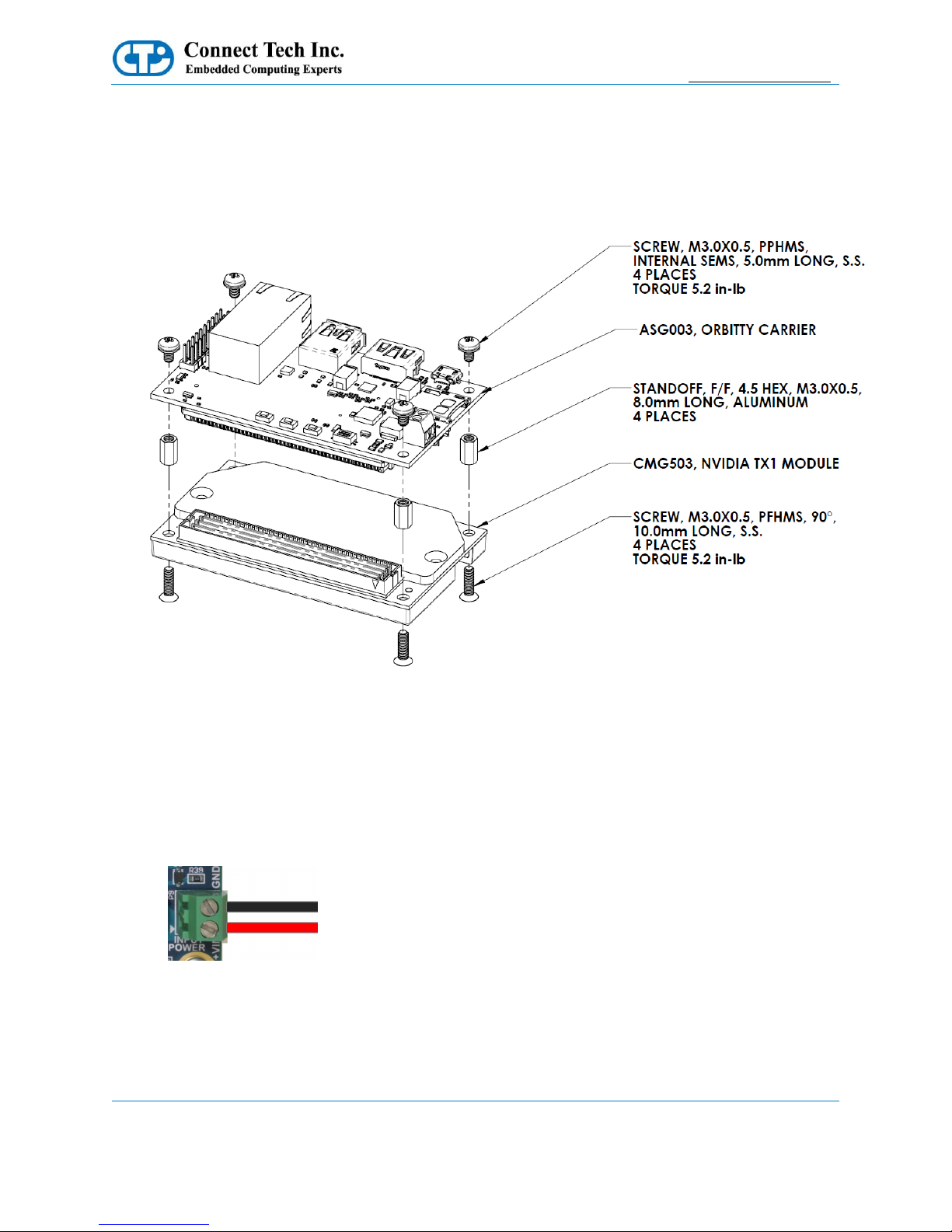
Typical Installation
1. Ensure all external system power supplies are off.
2. Install the Jetson TX1 Module onto the Orbitty Carrier as shown below:
3. Install the necessary cables for application. At a minimum these would include:
a) HDMI video display cable
b) Keyboard and mouse via USB
For additional information on the relevant cables, please see the Cables and Interconnects section of this
manual.
4. Connect the main power input to the Wire-to-Board Screw Terminal on board as shown below:
+9V to +15V to the +VIN terminal and Ground to the GND terminal.
5. Switch ON the Power Supply. DO NOT power up your system by plugging in live power.
Page 21
Orbitty Carrier for Jetson™ TX1
Users Guide
www.connecttech.com
Document: CTIM-00471
Revision: 0.05
Page 21 of 27
Connect Tech Inc. 800-426-8979 | 519-836-1291
Date: 2016/12/01
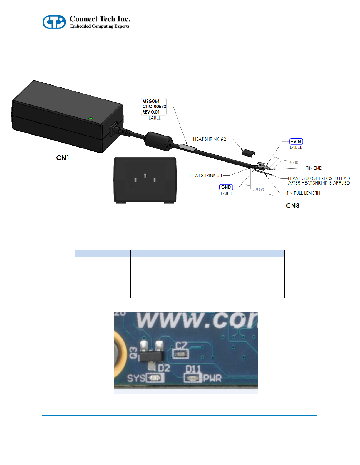
Power Supply
Connect Tech offers a 12V 5A power supply preconfigured for the ASG003. It is supplied by a standard AC
line cord and has a cable length of approximately 1.5m. Contact our sales department about the MSG064 for
more details.
On-Board Indicator LED’s
The Orbitty Carrier has 2 on-board indicator LEDs.
LED Designator
Description
D11
Power Good Indicator
- If this LED is ON, this indicates that all on-board
power supplies are ON and at the proper level.
D2
System Status Indicator
- If this LED is ON, it indicates the TX1 module has
powered ON.
Page 22

Orbitty Carrier for Jetson™ TX1
Users Guide
www.connecttech.com
Document: CTIM-00471
Revision: 0.05
Page 22 of 27
Connect Tech Inc. 800-426-8979 | 519-836-1291
Date: 2016/12/01
Current Consumption Details
Below are the maximum ratings of the Orbitty Carrier.
Theoretical Maximum
Amps
Watts
Theoretical absolute maximum total draw of all functionality on the
board
1.75
21
Below are measurements taken with the Orbitty Carrier running in various configurations. Some values will
change depending on what operation or software is installed. Please refer to the module manufacturer’s manual
for full details on the current consumption of the particular module you are using.
All measurements below are used with +12V applied to the Input Power Connector.
Actual Measurements
Amps
Watts
Orbitty Carrier standalone no module installed, powered ON, with no
loads
0.03
0.36
Module Installed, Ubuntu in headless mode, remote operation over
serial console
0.12
1.44
Module Installed, single HDMI video output, Keyboard, Mouse and
Ethernet conenctted.System sitting at Ubuntu Desktop (GUI) in idle
operation
0.20
2.4
Module Installed, single HDMI video output, USB 3.0 Camera
Connected, USB OTG connected with a Keyboard, and system running
cpu stress test and glxgears GPU test
0.71
8.52
Page 23

Orbitty Carrier for Jetson™ TX1
Users Guide
www.connecttech.com
Document: CTIM-00471
Revision: 0.05
Page 23 of 27
Connect Tech Inc. 800-426-8979 | 519-836-1291
Date: 2016/12/01
Software / BSP Details
NVIDIA Linux For Tegra (L4T)
The Orbitty Carrier is designed to be used with the stock NVIDIA Linux For Tegra (L4T) Builds. HDMI,
Gigabit Ethernet, USB 3.0, USB OTG (Host & Client), UARTs, GPIO, SD Card and I2C will all be supported
natively with no BSP modifications needed. Please note that Fan PWM (speed control) is NOT natively
supported by the stock L4T builds. If users wish to use the native builds you must enable the S1 DIP Switch to
put the Fan into the Always On mode.
NVIDIA’s L4T can be downloaded directly from NVIDIA here:
https://developer.nvidia.com/embedded/linux-tegra
NVIDIA Jetpack for L4T
The JetPack for L4T is an on-demand all-in-one package that bundles and installs all software tools required to
develop for the NVIDIA’s TX1 Platform with Connect Tech’s TX1 Carrier boards. JetPack includes host and
target development tools, APIs and packages (OS images, tools, APIs, middleware, samples, documentation
including compiling samples) to enable developers to jump start their development environment for developing
with the Jetson Embedded Platform. The latest release of JetPack runs on an Ubuntu 14.04 Linux 64-bit host
system and supports both the latest Jetson TX1 Development Kit and Jetson TK1 Development Kit.
NVIDIA’s Jetpack can be downloaded directly from NVIDIA here:
https://developer.nvidia.com/embedded/jetpack
Connect Tech’s Custom L4T BSP (CTI-L4T)
Connect Tech also offers a custom BSP to add in additional peripheral support on CTI’s TX1 Carrier Boards.
In the case of the Orbitty Carrier board the CTI-L4T will expose software control of the TX1 Fan PWM (Fan
Speed Control). Once the CTI-L4T is deployed, users must enable the S1 DIP Switch to put the Fan into the
PWM Enabled mode, to use this feature. Other features and add-ons will be added into the CTI-L4T in the
future, please see the README file in the CTI-L4T package for full details.
The CTI-L4T can be downloaded directly from Connect Tech here:
http://www.connecttech.com/sub/Products/ASG002.asp
Page 24

Orbitty Carrier for Jetson™ TX1
Users Guide
www.connecttech.com
Document: CTIM-00471
Revision: 0.05
Page 24 of 27
Connect Tech Inc. 800-426-8979 | 519-836-1291
Date: 2016/12/01
Force Recovery Mode
To update your system, you will need to be in Force USB Recovery Mode so you can transfer system software to the
developer board. When in Force USB Recovery Mode, you are able to update system software and write the boot
loader, boot configuration table (BCT), and partition configuration to the device.
See the Platform Software documentation for OS specific instructions when updating system software on your
developer board.
CAUTION: ALWAYS CONNECT ALL EXTERNAL PERIPHERAL DEVICES BEFORE CONNECTING THE
INPUT POWER SUPPLY
Connecting a device while powered on may damage the Orbitty Carrier or peripheral device.
Procedure to place system in Force USB Recovery Mode:
1) Power OFF the Orbitty. The Orbitty MUST be powered OFF, and not in a suspend or sleep state.
2) Use a USB Micro-B to USB Type-A Cable. Plug the Micro-B end into the Orbitty USB OTG port. Plug the
USB Type-A end into a host PC.
3) Power ON the Orbitty.
4) (Press and release the POWER button, if necessary) Press and hold the RECOVERY button; while depressing the
RECOVERY button, press and release the RESET button; wait two seconds and release the RECOVERY button.
Note: When in Force USB Recovery Mode, the development system will not boot up (nothing appears on display or
serial port).
After successfully updating the system software and restarting your developer board, the system will continue
through the boot up process.
Page 25

Orbitty Carrier for Jetson™ TX1
Users Guide
www.connecttech.com
Document: CTIM-00471
Revision: 0.05
Page 25 of 27
Connect Tech Inc. 800-426-8979 | 519-836-1291
Date: 2016/12/01
Thermal Details
The Orbitty Carrier Board has an Operating Temperature Range of -40°C to +85°C.
However, it is important to note that the NVIDIA Jetson TX1 Module has its own properties separate to that of
the Orbitty Carrier Board.
Customer responsibility requires proper implementation of a thermal solution that maintains the TX1 SoC and
Thermal Transfer Plate (TTP) temperatures below the specified temperatures (shown in the table below) under
the maximum thermal load and system conditions for their use case.
Parameter
Value
Units
Maximum Orbitty Carrier Operating Temperature
85
°C
Maximum TX1 TTP Operating Temperature
80
°C
Maximum TX1 CPU Operating Temperature
89
°C
Maximum TX1 GPU Operating Temperature
90.5
°C
TX1 CPU Shutdown Temperature
103
°C
TX1 GPU Shutdown Temperature
104
°C
NVIDIA provides a complete Thermal Design Guide, which includes all of the information required to
implement a complete thermal solution for Jetson TX1 Module. The Thermal Design Guide can be
downloaded here:
http://developer.nvidia.com/embedded/dlc/jetson-tx1-thermal-design-guide
Page 26

Orbitty Carrier for Jetson™ TX1
Users Guide
www.connecttech.com
Document: CTIM-00471
Revision: 0.05
Page 26 of 27
Connect Tech Inc. 800-426-8979 | 519-836-1291
Date: 2016/12/01
Mechanical Details
3D STEP Model
A complete 3D STEP Model file of the Orbitty Carrier can be downloaded here:
http://www.connecttech.com/ftp/3d_models/ASG003_3D_MODEL.zip
2D Dimensions Drawing
Page 27

Orbitty Carrier for Jetson™ TX1
Users Guide
www.connecttech.com
Document: CTIM-00471
Revision: 0.05
Page 27 of 27
Connect Tech Inc. 800-426-8979 | 519-836-1291
Date: 2016/12/01
Stack-up Drawing
Cables
The Orbitty Carrier does not require any special external cables.
Standard USB, HDMI and Ethernet Cabling can be used.
 Loading...