

Page 1

Elroy Carrier for NVIDIA® Jetson™
TX2/TX2i/TX1
Users Guide
Connect Tech Inc. Tel: 519-836-1291
42 Arrow Road Toll: 800-426-8979 (North America only)
Guelph, Ontario Fax: 519-836-4878
N1K 1S6 Email: sales@connecttech.com
www.connecttech.com support@connecttech.com
CTIM-00465 Revision 0.16 2018-11-29
Page 2

Elroy Carrier for NVIDIA® Jetson™ TX2/TX2i/TX1
Users Guide
www.connecttech.com
Document: CTIM-00465
Revision: 0.16
Page 2 of 30
Connect Tech Inc. 800-426-8979 | 519-836-1291
Date: 2019-02-20
Table of Contents
Table of Contents ................................................................................................................................... 2
Preface ................................................................................................................................................... 4
Disclaimer ....................................................................................................................................................... 4
Customer Support Overview ........................................................................................................................... 4
Contact Information ........................................................................................................................................ 4
Limited Product Warranty ............................................................................................................................... 5
Copyright Notice ............................................................................................................................................. 5
Trademark Acknowledgment .......................................................................................................................... 5
ESD Warning .................................................................................................................................................. 6
Revision History .................................................................................................................................... 6
Introduction........................................................................................................................................... 7
Product Features and Specifications ...................................................................................................... 7
Product Overview .................................................................................................................................. 8
Block Diagram ................................................................................................................................................ 8
Connector Locations – Top Side ..................................................................................................................... 9
Connector Locations – Bottom Side .............................................................................................................. 10
Connector Summary ...................................................................................................................................... 11
DIP Switch Summary & Locations ............................................................................................................... 11
Detailed Feature Description ................................................................................................................ 12
Jetson™ TX2/TX2i/TX1 Board-to-Board Connector ................................................................................... 12
Jetson™ TX2, TX2i or TX1 Compatibility ................................................................................................... 13
HDMI Connector ........................................................................................................................................... 15
System ........................................................................................................................................................... 15
Mini-PCIe/mSATA Slots .............................................................................................................................. 17
Dual Function Mini-PCIe/mSATA Slots ............................................................................................ 17
Half and Full Length Mini-PCIe/mSATA Module Installation .......................................................... 18
USB 2.0/3.0 ................................................................................................................................................... 20
Serial ............................................................................................................................................................. 21
Serial Configuration ........................................................................................................................... 21
Dual RS-232 ............................................................................................................................................ 22
Serial 0 RS-232/Serial 1 RS-485 ............................................................................................................. 22
Dual RS-485 ............................................................................................................................................ 22
Dual Disable ............................................................................................................................................ 22
Power Input ................................................................................................................................................... 23
Auto Start............................................................................................................................................ 23
Switch Description ............................................................................................................................... 24
SW1 DIP Switch – Carrier Control ............................................................................................................... 24
Typical Installation .............................................................................................................................. 25
Power Supply ....................................................................................................................................... 26
On-Board Indicator LED’s .................................................................................................................. 26
Current Consumption Details .............................................................................................................. 26
Software / BSP Details ......................................................................................................................... 27
Connect Tech’s Custom L4T BSP (CTI-L4T) .............................................................................................. 27
Page 3

Elroy Carrier for NVIDIA® Jetson™ TX2/TX2i/TX1
Users Guide
www.connecttech.com
Document: CTIM-00465
Revision: 0.16
Page 3 of 30
Connect Tech Inc. 800-426-8979 | 519-836-1291
Date: 2019-02-20
NVIDIA Linux For Tegra (L4T) ................................................................................................................... 27
NVIDIA Jetpack for L4T .............................................................................................................................. 27
Thermal Details ................................................................................................................................... 28
Mechanical Details ............................................................................................................................... 29
Top View ....................................................................................................................................................... 29
Cables .................................................................................................................................................. 30
Cable Kits ...................................................................................................................................................... 30
Page 4

Elroy Carrier for NVIDIA® Jetson™ TX2/TX2i/TX1
Users Guide
www.connecttech.com
Document: CTIM-00465
Revision: 0.16
Page 4 of 30
Connect Tech Inc. 800-426-8979 | 519-836-1291
Date: 2019-02-20
Preface
Disclaimer
The information contained within this user’s guide, including but not limited to any product specification, is
subject to change without notice.
Connect Tech assumes no liability for any damages incurred directly or indirectly from any technical or
typographical errors or omissions contained herein or for discrepancies between the product and the user’s
guide.
Customer Support Overview
If you experience difficulties after reading the manual and/or using the product, contact the Connect Tech
reseller from which you purchased the product. In most cases the reseller can help you with product installation
and difficulties.
In the event that the reseller is unable to resolve your problem, our highly-qualified support staff can assist
you. Our support section is available 24 hours a day, 7 days a week on our website at:
http://connecttech.com/support/. See the contact information section below for more information on how to
contact us directly. Our technical support is always free.
Contact Information
Mail/Courier
Connect Tech Inc.
Technical Support
42 Arrow Road
Guelph, Ontario
Canada N1K 1S6
Email/Internet
sales@connecttech.com
support@connecttech.com
www.connecttech.com
Note:
Please go to the Connect Tech Resource Center for product manuals, installation guides, device drivers,
BSPs and technical tips. Submit your technical support questions to our support engineers.
Telephone/Facsimile
Technical Support representatives are ready to answer your call Monday through Friday, from 8:30 a.m. to
5:00 p.m. Eastern Standard Time. Our numbers for calls are:
Toll Free: 800-426-8979 (North America only)
Telephone: 519-836-1291 (Live assistance available 8:30 a.m. to 5:00 p.m. EST, Monday to Friday)
Facsimile: 519-836-4878 (on-line 24 hours)
Page 5

Elroy Carrier for NVIDIA® Jetson™ TX2/TX2i/TX1
Users Guide
www.connecttech.com
Document: CTIM-00465
Revision: 0.16
Page 5 of 30
Connect Tech Inc. 800-426-8979 | 519-836-1291
Date: 2019-02-20
Limited Product Warranty
Connect Tech Inc. provides a one year Warranty for the Elroy Carrier. Should this product, in Connect Tech
Inc.'s opinion, fail to be in good working order during the warranty period, Connect Tech Inc. will, at its
option, repair or replace this product at no charge, provided that the product has not been subjected to abuse,
misuse, accident, disaster or non-Connect Tech Inc. authorized modification or repair.
You may obtain warranty service by delivering this product to an authorized Connect Tech Inc. business
partner or to Connect Tech Inc. along with proof of purchase. Product returned to Connect Tech Inc. must be
pre-authorized by Connect Tech Inc. with an RMA (Return Material Authorization) number marked on the
outside of the package and sent prepaid, insured and packaged for safe shipment. Connect Tech Inc. will
return this product by prepaid ground shipment service.
The Connect Tech Inc. Limited Warranty is only valid over the serviceable life of the product. This is defined
as the period during which all components are available. Should the product prove to be irreparable, Connect
Tech Inc. reserves the right to substitute an equivalent product if available or to retract the Warranty if no
replacement is available.
The above warranty is the only warranty authorized by Connect Tech Inc. Under no circumstances will
Connect Tech Inc. be liable in any way for any damages, including any lost profits, lost savings or other
incidental or consequential damages arising out of the use of, or inability to use, such product.
Copyright Notice
The information contained in this document is subject to change without notice. Connect Tech Inc. shall not
be liable for errors contained herein or for incidental consequential damages in connection with the furnishing,
performance, or use of this material. This document contains proprietary information that is protected by
copyright. All rights are reserved. No part of this document may be photocopied, reproduced, or translated to
another language without the prior written consent of Connect Tech, Inc.
Copyright © 2017 by Connect Tech, Inc.
Trademark Acknowledgment
Connect Tech, Inc. acknowledges all trademarks, registered trademarks and/or copyrights referred to in this
document as the property of their respective owners. Not listing all possible trademarks or copyright
acknowledgments does not constitute a lack of acknowledgment to the rightful owners of the trademarks and
copyrights mentioned in this document.
Page 6

Elroy Carrier for NVIDIA® Jetson™ TX2/TX2i/TX1
Users Guide
www.connecttech.com
Document: CTIM-00465
Revision: 0.16
Page 6 of 30
Connect Tech Inc. 800-426-8979 | 519-836-1291
Date: 2019-02-20
ESD Warning
Electronic components and circuits are sensitive to
ElectroStatic Discharge (ESD). When handling any circuit
board assemblies including Connect Tech carrier
assemblies, it is recommended that ESD safety
precautions be observed. ESD safe best practices include,
but are not limited to:
• Leaving circuit boards in their antistatic packaging
until they are ready to be installed.
• Using a grounded wrist strap when handling circuit
boards, at a minimum you should touch a grounded
metal object to dissipate any static charge that may be
present on you.
• Only handling circuit boards in ESD safe areas, which
may include ESD floor and table mats, wrist strap
stations and ESD safe lab coats.
• Avoiding handling circuit boards in carpeted areas.
• Try to handle the board by the edges, avoiding contact
with components.
Revision History
Revision
Date
Changes
0.00
2016/04/28
Initial Release
0.01
2016/06/13
Added more technical information throughout the document
0.02
2016/07/07
Fixed formatting on thermal section
0.03
2016/10/06
Added information on USB Recovery Mode & fixed minipcie pinout
0.04
2016/10/14
Revised information on USB recovery & added note on video input
0.05
2016/11/16
Updated assembly drawings
0.06
2016/11/24
Added note on power supply, MSG063
0.07
2017/04/18
Updated MSG063 Cable Drawing
0.08
2017/04/24
Added Note on P8, Added tags on mPCIe Pinout table
0.09
2017/05/26
Updated power supplies; added TX2 specs
0.10
2017/08/04
Added cable drawing links, removed drawings from doc
0.11
2017/11/08
Added TX1/TX2 Compatibility information, updated block diagram,
updated SW section
0.12
2017/12/06
Updated power specifications
0.13
2018/01/05
Revised cable information
0.14
2018/03/08
Added GPIO KDB link
0.15
2018/07/30
Added TX2i compatibility
0.16
2019/02/20
Added TX2i power circuitry note, pinouts to all photos, P4B to Video
Input, notes on CSI connection and SPI lanes
Page 7

Elroy Carrier for NVIDIA® Jetson™ TX2/TX2i/TX1
Users Guide
www.connecttech.com
Document: CTIM-00465
Revision: 0.16
Page 7 of 30
Connect Tech Inc. 800-426-8979 | 519-836-1291
Date: 2019-02-20
Introduction
Connect Tech’s Elroy Carrier for NVIDIA® Jetson™ TX2/TX2i/TX1 brings a low cost deployable Jetson™ TX2,
TX2i or TX1 Solution to the market. Designed to match the NVIDIA® Jetson™ TX2, TX2i or TX1 module form
factor, the Elroy’s design includes Dual MIPI CSI-2 Video Inputs, Mini-PCIe/mSATA expansion, Gigabit Ethernet,
HDMI Video, USB 3.0 and 2.0, and two Serial Ports for RS-232/485.
All of this is designed for use in a small form factor rugged environment. With locking pin-header connectors,
solder in standoffs, and industrial temperature range components, the Elroy is going places.
Product Features and Specifications
Feature
Elroy Carrier for NVIDIA® Jetson™ TX2/TX2i/TX1
Module Compatibility
NVIDIA® Jetson™ TX2, TX2i or TX1
PCB Size / Overall Size
87mm x 50mm (3.425” x 1.968”)
3D STEP Model: download here
Display
1x HDMI
Ethernet
1x Gigabit Ethernet (10/100/1000)
USB
1x USB 3.0 (Integrated USB 2.0)
1x USB 2.0
SATA
1x mSATA Half or Full Size
(Use of Full Size Removes Secondary Mini-PCIe Slot)
Audio
HDMI Integrated
Serial
2x RS-232/RS-485
Mini-PCIe/mSATA
1x Mini-PCIe/mSATA Half or Full Size
(Use of Full Size Removes Secondary Mini-PCIe Slot)
1x Mini-PCIe Half Size
SD Card
1x microSD Card Slot
Video Input
2x 2-Lane MIPI CSI 2.0
Misc.
1x I2C Link
1x SPI Link
1x System Control
4x GPIO
Power Requirements
+9V to +14V DC Input Range
Operating Temperature
-40oC to +85oC
Weight
35g
Accessories
Cable Kit
Warranty and Support
1 Year Warranty and Free Support
Page 8

Elroy Carrier for NVIDIA® Jetson™ TX2/TX2i/TX1
Users Guide
www.connecttech.com
Document: CTIM-00465
Revision: 0.16
Page 8 of 30
Connect Tech Inc. 800-426-8979 | 519-836-1291
Date: 2019-02-20
Product Overview
Block Diagram
Page 9

Elroy Carrier for NVIDIA® Jetson™ TX2/TX2i/TX1
Users Guide
www.connecttech.com
Document: CTIM-00465
Revision: 0.16
Page 9 of 30
Connect Tech Inc. 800-426-8979 | 519-836-1291
Date: 2019-02-20
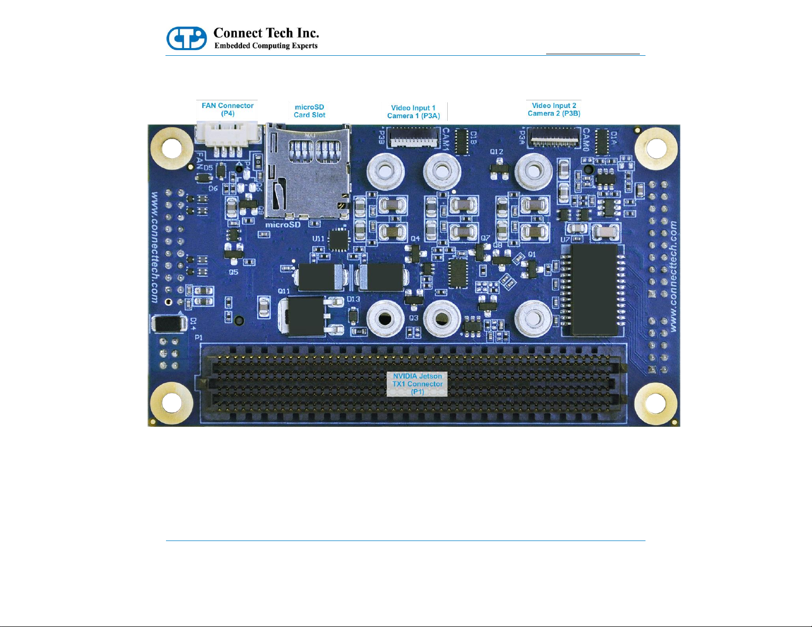
Connector Locations – Top Side
Page 10
Elroy Carrier for NVIDIA® Jetson™ TX2/TX2i/TX1
Users Guide
www.connecttech.com
Document: CTIM-00465
Revision: 0.16
Page 10 of 30
Connect Tech Inc. 800-426-8979 | 519-836-1291
Date: 2019-02-20
Connector Locations – Bottom Side
Page 11

Elroy Carrier for NVIDIA® Jetson™ TX2/TX2i/TX1
Users Guide
www.connecttech.com
Document: CTIM-00465
Revision: 0.16
Page 11 of 30
Connect Tech Inc. 800-426-8979 | 519-836-1291
Date: 2019-02-20
Connector Summary
Designator
Connector
Description
P1
NVIDIA Jetson
TX2/TX2i/TX1
NVIDIA Jetson TX2/TX2i/TX1 Module Connector
P2
HDMI Port
HDMI FCI MiniTek Connector
P3A
Video Input 1
MIPI CSI-0 Camera Input Connector
P3B
Video Input 2
MIPI CSI-1 Camera Input Connector
P4
Fan
NVIDIA Jetson TX2/TX2i/TX1 ACES Fan Connector
P5
System Port
System Port FCI MiniTek Connector
P6
Gigabit Ethernet Port
Gigabit Ethernet (10/100/1000) FCI MiniTek Connector
P7
microSD Card Slot
P8
Mini-PCIe Slot
Mini-PCIe Half Sized Card Slot
P9
Mini-PCIe/mSATA
Slot
Mini-PCIe/mSATA Half or Full Sized Card Slot
P10
USB 2.0/3.0 Ports 0-1
USB 2.0/3.0 Links 0 and 1 Intel Style Locking Connector
P11
Serial
Dual RS-232/RS485 FCI MiniTek Connector
P12
Input Power
Input Power FCI MiniTek Connector
DIP Switch Summary & Locations
Designator
Function
Description
SW1A
Mini-PCIe/mSATA
Selection (P3)
DIP Switch for Selecting Mini-PCIe/mSATA Slot (P3) Operation
SW1B
Serial Selection
DIP Switch for Controlling Serial Format and Related Feature
SW1C
Serial Selection
DIP Switch for Controlling Serial Format and Related Feature
SW1D
Serial Selection
DIP Switch for Controlling Serial Format and Related Feature
SW1E
Serial Selection
DIP Switch for Controlling Serial Format and Related Feature
SW1F
Serial Selection
DIP Switch for Controlling Serial Format and Related Feature
SW1G
Serial Selection
DIP Switch for Controlling Serial Format and Related Feature
SW1H
Multiple Use Cases
See Jetson™ TX2, TX2i or TX1 Compatibility section for
information
Page 12

Elroy Carrier for NVIDIA® Jetson™ TX2/TX2i/TX1
Users Guide
www.connecttech.com
Document: CTIM-00465
Revision: 0.16
Page 12 of 30
Connect Tech Inc. 800-426-8979 | 519-836-1291
Date: 2019-02-20
Detailed Feature Description
Jetson™ TX2/TX2i/TX1 Board-to-Board Connector
With the NVIDIA Jetson™ TX2/TX2i/TX1, the processor and chipset are implemented on the Jetson™
TX2/TX2i/TX1 Module. This connects to the Elroy Carrier via a Samtec SEARAY™ Board to Board
Connector.
Function
NVIDIA Jetson™ TX2, TX2i or TX1 Interface
Location
P1
Type
Samtec SEARAY™ Connector
Carrier
Connector
P/N
SEAM-50-03.0-S-08-2-A-K-TR (8.0mm stacking height)
Manufacturer: Samtec
Mating
Connector
P/N
SEAF-50-05-S-08-02-A-K (installed on Jetson™
TX2/TX2i/TX1)
Manufacturer: Samtec
Pinout
Refer to NVIDIA’s Jetson™ TX2/TX2i/TX1 System-onModule datasheet for pinout details
Standoffs
8.0mm Standoffs Required between NVIDIA Jetson
TX2/TX2i/TX1 Module and Elroy (ASG002) Carrier
Page 13

Elroy Carrier for NVIDIA® Jetson™ TX2/TX2i/TX1
Users Guide
www.connecttech.com
Document: CTIM-00465
Revision: 0.16
Page 13 of 30
Connect Tech Inc. 800-426-8979 | 519-836-1291
Date: 2019-02-20
Jetson™ TX2, TX2i or TX1 Compatibility
Due to pin-muxing within the Jetson™ TX2, TX2i and TX1 modules, the Elroy Carrier features a DIP switch
setting that will ensure full compatibility depending on which Jetson™ module you use. This DIP switch
setting is only present on board revisions F and later. Elroy Carrier board revisions E and earlier do not offer
full Jetson™ TX2 or TX2i compatibility and this DIP switch setting serves a different purpose on revision E
and earlier. Please see the table below for more information.
To determine which revision of the Elroy Carrier you have please see the revision label as per the image
below.
Function
Jetson™ TX2, TX2i or TX1 Select Switch
Location
SW1 – “H” Switch
Type
DIP Switch
Description
For revisions F and later:
If you are using a Jetson™ TX1 then leave the “H”
switch in the OFF position to ensure full compatibility.
If you are using a Jetson™ TX2/TX2i then leave the “H”
switch in the ON position to ensure full compatibility.
“H” switch OFF = Full Jetson™ TX1 Support
“H” switch ON = Full Jetson™ TX2/TX2i Support
For revision E and earlier:
DIP Switch for Grounding +3.3V_RTC, which will
Ground the VDD_RTC (Pin 50) on the NVIDIA Jetson
Module.
“H” switch ON = connects +3.3V_RTC to ground
For the other switch settings on SW1, please see the
Switch Description section of this document.
For further information please see the following notice regarding Astro Carrier compatibility:
• http://connecttech.com/resource-center/kdb344-cti-nvidia-jetson-carrier-board-tx2-tx1-compatibility/
Page 14
Elroy Carrier for NVIDIA® Jetson™ TX2/TX2i/TX1
Users Guide
www.connecttech.com
Document: CTIM-00465
Revision: 0.16
Page 14 of 30
Connect Tech Inc. 800-426-8979 | 519-836-1291
Date: 2019-02-20
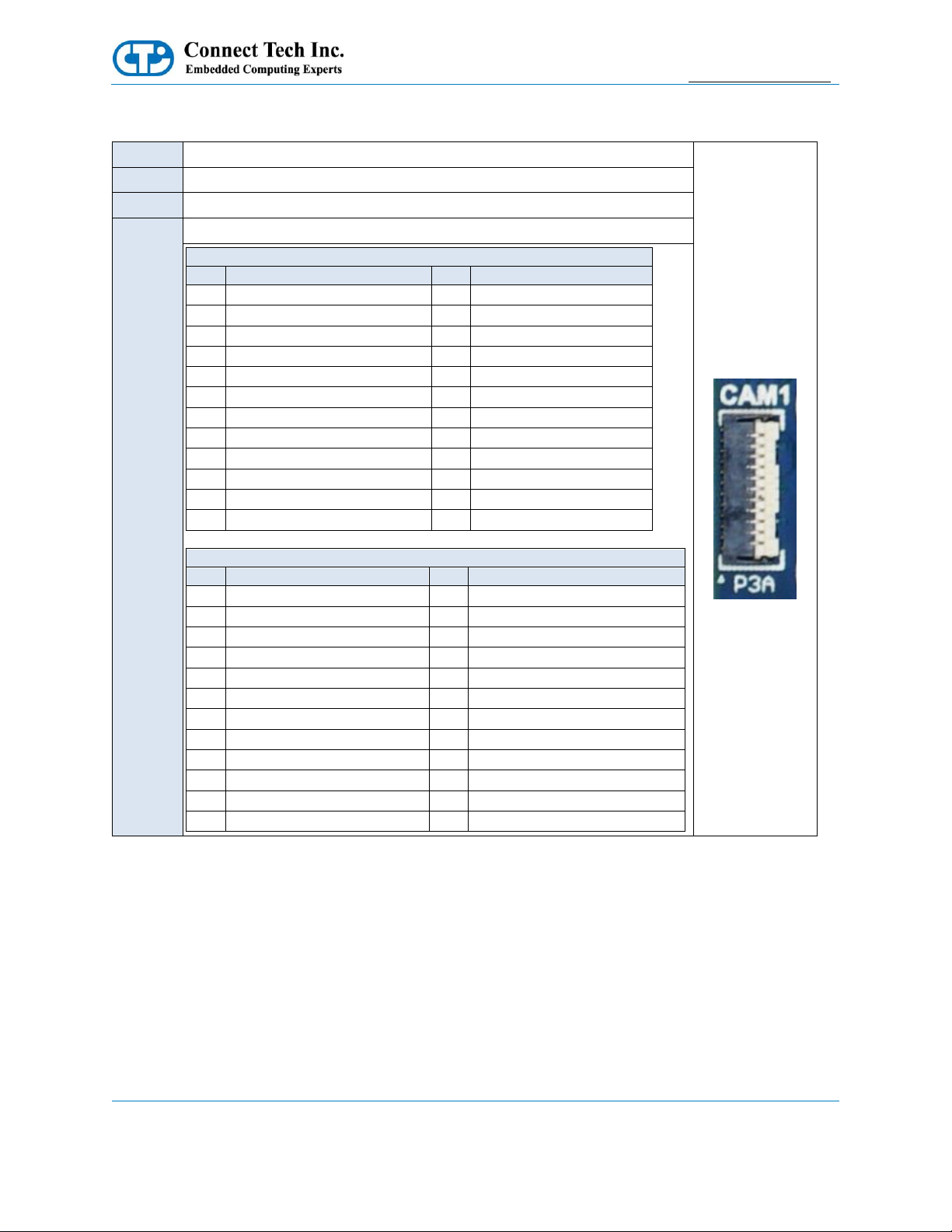
Video Input
Function
Video Input/Camera
Location
P3A, P3B
Type
Panasonic Flat Flex Cable Connector
P/N
AYF332335
Pinout
P4A
Pin
Description
Pin
Description
1
+1.8V
2
+1.8V
3
GND
4
CSI0_DATA0_P
5
CSI0_DATA0_N
6
GND
7
CSI0_CLK_P
8
CSI0_CLK_N
9
GND
10
CSI0_DATA1_P
11
CSI0_DATA1_N
12
GND
13
CAM0_MCLK
14
CAM0_PWR
15
GND
16
I2C_CAM_DATA
17
I2C_CAM_CLK
18
CAM0_RST
19
(NC)
20
GND
21
+2.8V
22
(NC)
23
GND
P4B
Pin
Description
Pin
Description
1
+1.8V
2
+1.8V
3
GND
4
CSI1_DATA0_P
5
CSI1_DATA0_N
6
GND
7
CSI1_CLK_P
8
CSI1_CLK_N
9
GND
10
CSI1_DATA1_P
11
CSI1_DATA1_N
12
GND
13
CAM1_MCLK
14
CAM1_PWR
15
GND
16
I2C_GP0_DATA
17
I2C_GP0_CLK
18
CAM1_RST
19
(NC)
20
GND
21
+2.8V
22
(NC)
23
GND
Note: This connector can accept cables with contacts facing both up and down. Ensure you are installing the cable
correctly by verifying with the pinout above. Failure to do so may damage the carrier. When installing the cable, the
pins should be facing the PCB, and the white line on the ribbon should face away from the PCB
Page 15

Elroy Carrier for NVIDIA® Jetson™ TX2/TX2i/TX1
Users Guide
www.connecttech.com
Document: CTIM-00465
Revision: 0.16
Page 15 of 30
Connect Tech Inc. 800-426-8979 | 519-836-1291
Date: 2019-02-20
HDMI Connector
Function
HDMI Connector
Location
P2
Type
FCI Minitek Double Row 10 x 2
P/N
98414-G06-20LF
Mating
10073599-020LF
Cable
CBG145
Pinout
Pin
Description
Pin
Description
1
TMDS2+
2
TMDS CLK+
3
TMDS2-
4
TMDS CLK-
5
GND
6
GND
7
TMDS1+
8
DDC DATA
9
TMDS1-
10
DDC CLK
11
GND
12
GND
13
TMDS0+
14
Hot Plug Detect
15
TMDS0-
16
GND
17
GND
18
GND
19
+5V
20
HDMI CEC
System
The System header can be used to connect the power button, reset button, and other system status required to
monitor the module performance or state. It also allows access to the Jetson TX2/TX2i/TX1 Module via I2C,
SPI (2 lanes), or GPIO.
Function
System Connector
Location
P5
Type
FCI Minitek Double Row 10 x 2
P/N
98424-G52-20LF
Mating
10073599-020LF
Cable
CBG116
Pinout
Pin
Description
Pin
Description 1 +5V
2
+3.3V_SB
3
SPI_CLK
4
PWRBTN#
5
SPI_MISO
6
FORCE_RECOV#
7
SPI_MOSI
8
BATLOW#
9
SPI_CS0#
10
RESET#
11
SPI_CS1#
12
GPIO8
13
RTC_BAT
14
GPIO9
15
I2C_CLK
16
GPIO_EXP0
17
I2C_DATA
18
GPIO_EXP1
19
GND
20
GND
Please reference our GPIO KDB for TX2/TX2i/TX1
values.
Page 16

Elroy Carrier for NVIDIA® Jetson™ TX2/TX2i/TX1
Users Guide
www.connecttech.com
Document: CTIM-00465
Revision: 0.16
Page 16 of 30
Connect Tech Inc. 800-426-8979 | 519-836-1291
Date: 2019-02-20
10/100/1000 Ethernet (GBE)
Function
Gigabit Ethernet Connector
Location
P6
Type
FCI Minitek Double Row 5 x 2
P/N
98414-G06-10LF
Mating
10073599-010LF
Cable
CBG117
Pinout
Pin
Description
Pin
Description
1
MX0-
2
MX0+
3
MX1-
4
MX1+
5
SHELL
6
SHELL
7
MX2-
8
MX2+
9
MX3-
10
MX3+
microSD Card Slot
Function
microSD Card Slot
Location
P7
Type
Molex microSD Memory Card Connector
P/N
502570-0893
Pinout
Pin
Description
Pin
Description
1
SDIO_DATA2
2
SDIO_DATA3
3
SDIO_CMD
4
SDIO_VCC
5
SDIO_CLK
6
GND
7
SDIO_DATA0
8
SDIO_DATA1
9
GND
10
SDIO_CD
NVIDIA Jetson TX2/TX2i/TX1 Fan
Function
NVIDIA Jetson TX2/TX2i/TX1 Fan Control
Location
P4
Type
Molex PicoBlade Header
P/N
53261-0471
Mating
51021-0400
Pinout
Pin
Description 1 GND
2
+5V
3
TACH
4
PWM
NOTE: Please note that FAN PWM (speed control) is NOT natively supported by the stock L4T builds. To enable
PWM functionality (speed control) users must deploy CTI-L4T BSP. Please see the software section of this
document for more details.
Page 17

Elroy Carrier for NVIDIA® Jetson™ TX2/TX2i/TX1
Users Guide
www.connecttech.com
Document: CTIM-00465
Revision: 0.16
Page 17 of 30
Connect Tech Inc. 800-426-8979 | 519-836-1291
Date: 2019-02-20
Mini-PCIe/mSATA Slots
Dual Function Mini-PCIe/mSATA Slots
The Elroy Carrier has a special dual purpose functional Mini-PCIe/mSATA slot (P9). This slot can accept
either a Mini-PCIe module or an mSATA SSD module. This slot has circuitry that allows for the selection
between connecting PCIe lanes or SATA lanes to the Connector. Finally, the slot also contains a USB 2.0 link
as per the Mini-PCIe specification.
See the block diagram for the Mini-PCIe/mSATA switching functionality.
Mini-PCIe/mSATA Switching Functionality Diagram
If a Mini-PCIe Card is placed into the Mini-PCIe/mSATA slot, then the Carrier Control DIP Switch (SW1A)
will select the SATA link routed to the Mini-PCIe/mSATA slot to be disconnected.
If however an mSATA Card is placed into the Mini-PCIe/mSATA slot, then the Carrier Control DIP Switch
(SW1A) will select the PCIe link routed to the Mini-PCIe/mSATA slot to be disconnected.
This allows for the following maximum configurations:
A. 1x Full Sized Mini-PCIe Card, with 0x mSATA Card
B. 2x Half Sized Mini-PCIe Cards, with 0x mSATA Card
C. 1x Half Sized Mini-PCIe Card, with 1x Half Sized mSATA Card
D. 0x Mini-PCIe Card, with 1x Full Sized mSATA Card
Carrier Control DIP Switch Selection
Switch Location
Switch ON
Switch OFF
SW1A
Mini-PCIe Slot
mSATA Slot
NOTE:
The Mini-PCie Card slot at P8 does not have USB2.0 capability, as such when using USB devices over this
interface the Mini-PCIe/mSATA at P9 must be used.
Page 18

Elroy Carrier for NVIDIA® Jetson™ TX2/TX2i/TX1
Users Guide
www.connecttech.com
Document: CTIM-00465
Revision: 0.16
Page 18 of 30
Connect Tech Inc. 800-426-8979 | 519-836-1291
Date: 2019-02-20
Half and Full Length Mini-PCIe/mSATA Module Installation
The Elroy Carrier is designed with mounting holes to allow for the population of full and half sized modules.
To switch between the sizes, simply move the spacers and screws to the appropriate position. See the images
below for further information.
Full-Size Mini-PCIe/mSATA Module installation:
Half-Size Mini-PCIe/mSATA Module installation:
Page 19

Elroy Carrier for NVIDIA® Jetson™ TX2/TX2i/TX1
Users Guide
www.connecttech.com
Document: CTIM-00465
Revision: 0.16
Page 19 of 30
Connect Tech Inc. 800-426-8979 | 519-836-1291
Date: 2019-02-20
Function
Mini-PCIe/mSATA Slots
Location
P8, P9
Type
Molex Card Edge Connector
P/N
48338-0065
Pinout
Pin
Mini-PCIe Description
mSATA Description
1 - -
2
+3.3V
+3.3V
3 - - 4 GND
GND
5 - -
6
+1.5V
+1.5V
7
CLKREQ#
- 8 - - 9
GND
GND
10 - -
11
PCIe CLK-
-
12 - -
13
PCIe CLK+
-
14 - -
15
GND
GND
16 - -
17 - -
18
GND
GND
19 - -
20
W_DISABLE#
-
21
RESV
RESV
22 - -
23
PCIe RX-
SATA TX+
24
+3.3V
+3.3V
25
PCIe RX+
SATA TX-
26
GND
GND
27
GND
GND
28
+1.5V
+1.5V
29
GND
GND
30 - -
31
PCIe TX-
SATA RX-
32 - -
33
PCIe TX+
SATA RX+
34
GND
GND
35
GND
GND
36
USB D- (P9 Only)
-
37
GND
GND
38
USB D+ (P9 Only)
-
39
+3.3V
+3.3V
40
GND
GND
41
+3.3V
+3.3V
42 - -
43
RESV
RESV
44 - -
45 - -
46 - -
47 - -
48
+1.5V
+1.5V
49 - -
50
GND
GND
51 - -
52
+3.3V
+3.3V
Page 20
Elroy Carrier for NVIDIA® Jetson™ TX2/TX2i/TX1
Users Guide
www.connecttech.com
Document: CTIM-00465
Revision: 0.16
Page 20 of 30
Connect Tech Inc. 800-426-8979 | 519-836-1291
Date: 2019-02-20
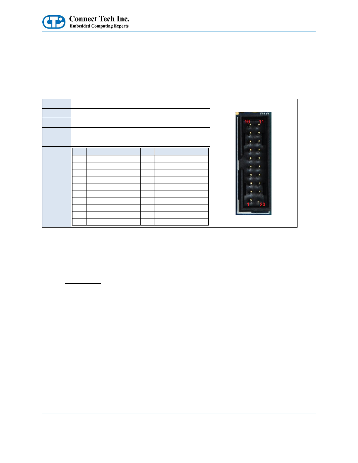
USB 2.0/3.0
The maximum configuration for a NVIDIA Jetson TX2, TX2i or TX1 Module allows for one external USB 3.0
Port with an integrated USB 2.0 Port. The USB 3.0 signals are sourced from the Jetson TX2/TX2i/TX1
Module, and run through a re-driver.
Over current protection, power supply filtering and ESD protection is provided on-board.
Function
USB 2.0/3.0
Location
P10
Type
Lotes Co. Ltd Double Row 10 x 2
P/N
ABA-USB-152-K01
Cable
CBG131
Pinout
Pin
Description
Pin
Description
1
Port A - VBUS
20
KEY
2
Port A - SSRX-
19
Port B - VBUS
3
Port A - SSRX+
18 - 4
GND
17 - 5
Port A - SSTX-
16
GND
6
Port A - SSTX+
15 - 7
GND
14 - 8
Port A - D-
13
GND
9
Port A - D+
12
Port B - D-
10 - 11
Port B - D+
Force USB Recovery Mode
The Elroy carrier supports flashing the TX2/TX2i/TX1 module over USB 2.0 using Port B. A standard
USB-A to USB-A cable is required to connect it to the flashing system. Note that you should leave the
USB cable unplugged until after the TX2/TX2i/TX1 is put into recovery mode.
To flash the TX2/TX2i/TX1, first ensure the unit is powered down. Next, connect pins 6 and 20 of the
System Header together with a jumper wire, then power on the unit. The jumper wire can be removed after
applying power. Connect the USB-A to USB-A cable from a free USB port on the host PC to the USB 2.0
port on the Elroy. The TX2/TX2i/TX11 can now be flashed using the standard NVIDIA flashing tools.
Page 21

Elroy Carrier for NVIDIA® Jetson™ TX2/TX2i/TX1
Users Guide
www.connecttech.com
Document: CTIM-00465
Revision: 0.16
Page 21 of 30
Connect Tech Inc. 800-426-8979 | 519-836-1291
Date: 2019-02-20
Serial
Function
Dual Serial (RS-232/RS-485)
Location
P11
Type
FCI Minitek Double Row 5 x 2
P/N
98424-G52-10LF
Mating
10073599-010LF
Cable
CBG104
Pinout
Pin
Description
1
Serial 0 - RS-232TX/RS-485TX+
2
Serial 0 - RS-232RX/RS-485RX+
3
Serial 0 - RS-485TX-
4
Serial 0 - RS-485RX-
5
GND
6
GND
7
Serial 1 - RS-232TX/RS-485TX+
8
Serial 1 - RS-232RX/RS-485RX+
9
Serial 1 - RS-485TX-
10
Serial 1 - RS-485RX-
UART0 = ttyS0 within Linux for Tegra
UART1 = ttyTHS2 within Linux for Tegra
Both channels are +/-5.5V RS-232 by default.
Serial Configuration
Two of the Serial UART links from the Jetson TX2/TX2i/TX1 Module are routed into an Exar SP336E
Transceiver. This enables the various selectable serial outputs (RS-232/RS-485). To configure the setting, the
appropriate configuration of the Serial Selection DIP Switch is required. Please refer to the Exar SP336E
datasheet for additional details.
Page 22

Elroy Carrier for NVIDIA® Jetson™ TX2/TX2i/TX1
Users Guide
www.connecttech.com
Document: CTIM-00465
Revision: 0.16
Page 22 of 30
Connect Tech Inc. 800-426-8979 | 519-836-1291
Date: 2019-02-20
Dual RS-232
Switch
Position
Description
G
OFF
Mode 0 Selection - RS-232 Selection
F
OFF
Serial Link 0 - RX+ BIAS
E
OFF
Serial Link 0 - RX- BIAS
D
OFF
Mode 1 Selection - RS-232 Selection
C
OFF
Serial Link 1 - RX+ BIAS
B
OFF
Serial Link 1 – RX- BIAS
Serial 0 RS-232/Serial 1 RS-485
Switch
Position
Description
G
OFF
Mode 0 Selection - RS-232 Selection
F
OFF
Serial Link 0 - RX+ BIAS
E
OFF
Serial Link 0 - RX- BIAS
D
ON
Mode 1 Selection - RS-232 Selection
C
USER
Serial Link 1 - RX+ BIAS
B
USER
Serial Link 1 – RX- BIAS
Dual RS-485
Switch
Position
Description
G
ON
Mode 0 Selection - RS-232 Selection
F
USER
Serial Link 0 - RX+ BIAS
E
USER
Serial Link 0 - RX- BIAS
D
OFF
Mode 1 Selection - RS-232 Selection
C
USER
Serial Link 1 - RX+ BIAS
B
USER
Serial Link 1 – RX- BIAS
Dual Disable
Switch
Position
Description
G
ON
Mode 0 Selection - RS-232 Selection
F
XX
Serial Link 0 - RX+ BIAS
E
XX
Serial Link 0 - RX- BIAS
D
ON
Mode 1 Selection - RS-232 Selection
C
XX
Serial Link 1 - RX+ BIAS
B
XX
Serial Link 1 – RX- BIAS
Page 23

Elroy Carrier for NVIDIA® Jetson™ TX2/TX2i/TX1
Users Guide
www.connecttech.com
Document: CTIM-00465
Revision: 0.16
Page 23 of 30
Connect Tech Inc. 800-426-8979 | 519-836-1291
Date: 2019-02-20
Power Input
The Elroy Carrier accepts a single power input to power all on-board devices. A power input range of +9V to
+14V is acceptable.
Function
Power
Location
P12
Type
FCI Minitek Double Row 3 x 2
P/N
98414-G06-06LF
Mating
10073599-006LF
Cable
CBG112
Pinout
Pin
Description
1
GND
2
GND
3
GND
4
+12.0V
5
+12.0V
6
+12.0V
Auto Start
The Elroy Carrier has an on-board Auto Start Functionality. The NVIDIA Jetson TX2/TX2i/TX1 Module
requires a power button or power pulse to start. The Elroy Carrier has a power pulse circuit on board to auto
start the Jetson TX2/TX2i/TX1.
Note: Due to the changes done to the PMIC circuitry of the TX2i Jetson Module the Elroy Carrier will always
remain ON when in AT (Automatic Power ON) and ATX (Push Power button) modes. This will cause the Elroy
Carrier to automatically power ON when voltage is applied to the system. The system will in addition be unable to
shut down in software (Soft Shutdown), due to the characteristics of the TX2i power circuitry as such the system
will perform a Reset/Reboot function.
Page 24

Elroy Carrier for NVIDIA® Jetson™ TX2/TX2i/TX1
Users Guide
www.connecttech.com
Document: CTIM-00465
Revision: 0.16
Page 24 of 30
Connect Tech Inc. 800-426-8979 | 519-836-1291
Date: 2019-02-20
Switch Description
The Elroy Carrier has a DIP Switch block for various on-board controls.
SW1 DIP Switch – Carrier Control
Function
Mini-PCIe/mSATA Selection, Serial Selection, RTC
Battery Operation
Location
SW1
Pinout
Switch
Description
SW1A
DIP Switch for Selecting MiniPCIe/mSATA Slot (P3) Operation
SW1B
DIP Switches for Controlling Serial
Format and Related Features
SW1C
DIP Switches for Controlling Serial
Format and Related Features
SW1D
DIP Switches for Controlling Serial
Format and Related Features
SW1E
DIP Switches for Controlling Serial
Format and Related Features
SW1F
DIP Switches for Controlling Serial
Format and Related Features
SW1G
DIP Switches for Controlling Serial
Format and Related Features
SW1H
For revisions F and later:
If you are using a Jetson™ TX1 then
leave the “H” switch in the OFF position
to ensure full compatibility.
If you are using a Jetson™ TX2/TX2i
then leave the “H” switch in the ON
position to ensure full compatibility.
“H” switch OFF = Full Jetson™ TX1
Support
“H” switch ON = Full Jetson™
TX2/TX2i Support
For revision E and earlier:
DIP Switch for Grounding +3.3V_RTC,
which will Ground the VDD_RTC (Pin
50) on the NVIDIA Jetson Module.
“H” switch ON = connects +3.3V_RTC
to ground
Page 25

Elroy Carrier for NVIDIA® Jetson™ TX2/TX2i/TX1
Users Guide
www.connecttech.com
Document: CTIM-00465
Revision: 0.16
Page 25 of 30
Connect Tech Inc. 800-426-8979 | 519-836-1291
Date: 2019-02-20
Typical Installation
1. Ensure all external system power supplies are off.
2. Install the Jetson TX2, TX2i or TX1 Module onto the Samtec SEARAY Connector P1. Be sure to follow
the manufacturer’s directions for proper installation of mounting hardware, heatsink/heatspreader, and any
other applicable requirements from the manufacturer.
3. Install the necessary cables for application. At a minimum these would include:
a) Power cable to the input power connector
b) HDMI video display cable
c) Keyboard and mouse via USB
For additional information on the relevant cables, please see the Cables and Interconnects section of this
manual.
4. Connect the Power Cable to the Power Supply
5. Switch ON the Power Supply. DO NOT power up your system by plugging in live power.
Page 26

Elroy Carrier for NVIDIA® Jetson™ TX2/TX2i/TX1
Users Guide
www.connecttech.com
Document: CTIM-00465
Revision: 0.16
Page 26 of 30
Connect Tech Inc. 800-426-8979 | 519-836-1291
Date: 2019-02-20
Power Supply
Connect Tech offers 12V 2A power supplies preconfigured for the ASG002. It is supplied by a standard AC
line cord and has a cable length of approximately 1.5m. Contact our sales department about the MSG063 or
MSG071 for more details. View the MSG063 drawing.
On-Board Indicator LED’s
The Elroy Carrier has 4 on-board indicator LEDs.
LED
Description
D7
GBE ACT#
D8
GBE LINK#
D15
+1.5V
D16
+3.3V_SB
Current Consumption Details
Below are the maximum ratings of the Elroy Carrier.
Theoretical Maximum
Watts
Theoretical absolute maximum total draw of all functionality on the
Elroy Carrier Board (not including TX2/TX2i/TX1 Module)
7.5
Below are measurements taken with the Elroy Carrier running in various configurations. Some values will
change depending on what operation or software is installed. Measurements also include the Jetson™
TX2/TX2i/TX1 Module. No mSATA or miniPCIe modules were installed while taking these measurements.
All measurements were taken in a lab environment with an ambient temperature of 25 degrees Celsius.
Actual Measurements
Watts
Module not installed, power applied to Elroy Carrier only
0.75
Module installed, booted into Ubuntu, idle
6.12
Module Installed, booted into Ubuntu, running a NVStreamer Demo
with a USB camera and 1080p video
12.3
Page 27

Elroy Carrier for NVIDIA® Jetson™ TX2/TX2i/TX1
Users Guide
www.connecttech.com
Document: CTIM-00465
Revision: 0.16
Page 27 of 30
Connect Tech Inc. 800-426-8979 | 519-836-1291
Date: 2019-02-20
Software / BSP Details
All Connect Tech NVIDIA Jetson TX2/TX2i/TX1 based products are built upon a modified Linux for Tegra
(L4T) Device Tree that is specific to each CTI product.
WARNING: The hardware configurations of CTI’s products differ from that of the NVIDIA supplied
evaluation kit. Please review the product documentation and install ONLY the appropriate CTI L4T BSPs.
Failure to follow this process could result in non-functional hardware.
Connect Tech’s Custom L4T BSP (CTI-L4T)
Connect Tech offers a custom BSP to add additional peripheral support on CTI’s Jetson Carrier Boards.The
CTI-L4T can be downloaded directly from Connect Tech here:
http://connecttech.com/product/rudi-embedded-system-for-nvidia-jetson-tx2-tx1/
BSPs, supporting documentation and release notes can be found at:
http://www.connecttech.com/jetson
http://connecttech.com/resource-center/cti-l4t-nvidia-jetson-board-support-package-release-notes/
NVIDIA Linux For Tegra (L4T)
The Rudi Embedded System is designed to be used with the stock NVIDIA Linux For Tegra (L4T) Builds.
However, the Connect Tech Board Support Package is required for full functionality.
NVIDIA’s L4T can be downloaded directly from NVIDIA here:
https://developer.nvidia.com/embedded/
NVIDIA Jetpack for L4T
The JetPack for L4T is an on-demand all-in-one package that bundles and installs all software tools required to
develop for the NVIDIA’s TX2/TX2i/TX1 Platform with Connect Tech’s Jetson Carrier Boards. JetPack
includes host and target development tools, APIs and packages (OS images, tools, APIs, middleware, samples,
documentation including compiling samples) to enable developers to jump start their development
environment for developing with the Jetson Embedded Platform. The latest release of JetPack runs on an
Ubuntu 14.04 Linux 64-bit host system and supports both the latest Jetson TX2/TX2i/TX1 Development Kit
and Jetson TK1 Development Kit.
NVIDIA’s Jetpack can be downloaded directly from NVIDIA here:
https://developer.nvidia.com/embedded/jetpack
Page 28
Elroy Carrier for NVIDIA® Jetson™ TX2/TX2i/TX1
Users Guide
www.connecttech.com
Document: CTIM-00465
Revision: 0.16
Page 28 of 30
Connect Tech Inc. 800-426-8979 | 519-836-1291
Date: 2019-02-20
Thermal Details
The Elroy Carrier Board has an Operating Temperature Range of -40°C to +85°C.
However, it is important to note that the NVIDIA Jetson TX2 and TX1 Modules have its own properties
separate to that of the Elroy Carrier Board. The NVIDIA Jetson TX2i matches the Elroy Operating
Temperature Range of -40°C to +85°C.
Customer responsibility requires proper implementation of a thermal solution that maintains the
TX2/TX2i/TX1 SoC and Thermal Transfer Plate (TTP) temperatures below the specified temperatures (shown
in the tables below) under the maximum thermal load and system conditions for their use case.
Jetson TX2i Thermal Specifications
Parameter
Value
Units
Maximum TTP operating temperature
85
°C
Recommended Tegra X2 operating temperature limit
T.cpu = 95.5
°C
T.gpu = 95.5
°C
Tegra X2 maximum operating temperature limit
T.cpu = 101
°C
T.gpu = 101
°C
T.diode = 110
°C
Jetson TX2/TX1 Thermal Specifications
Parameter
Value
Units
Maximum TTP operating temperature
80
°C
Recommended Tegra X2 operating temperature limit
T.cpu = 95.5
°C
T.gpu = 93.5
°C
Tegra X2 maximum operating temperature limit
T.cpu = 101
°C
T.gpu = 101
°C
NVIDIA provides complete Thermal Design Guides, which include all of the information required to
implement a complete thermal solution for the Jetson TX2, TX2i or TX1 Module. The Thermal Design Guides
can be downloaded here:
Jetson TX2i:
http://developer.nvidia.com/embedded/dlc/jetson-tx2i-thermal-design-guide
Jetson TX2/TX1:
http://developer.nvidia.com/embedded/dlc/jetson-tx2-thermal-design-guide
Page 29
Elroy Carrier for NVIDIA® Jetson™ TX2/TX2i/TX1
Users Guide
www.connecttech.com
Document: CTIM-00465
Revision: 0.16
Page 29 of 30
Connect Tech Inc. 800-426-8979 | 519-836-1291
Date: 2019-02-20
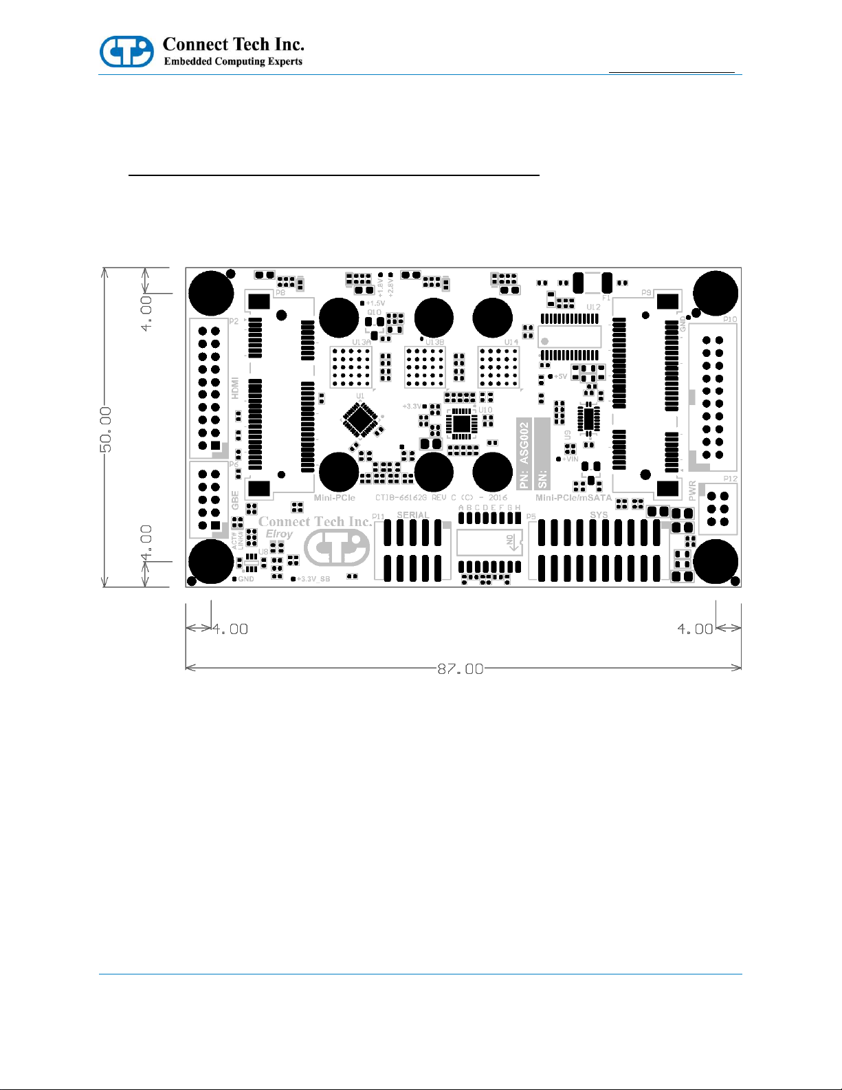
Mechanical Details
A complete 3D STEP Model file of Elroy Carrier can be downloaded here:
http://www.connecttech.com/ftp/3d_models/ASG002_3D_MODEL.zip
2D Mechanical Dimensioned Drawing (Top View) - PCB and Mounting Hole Dimension are in mil.
Top View
Page 30
Elroy Carrier for NVIDIA® Jetson™ TX2/TX2i/TX1
Users Guide
www.connecttech.com
Document: CTIM-00465
Revision: 0.16
Page 30 of 30
Connect Tech Inc. 800-426-8979 | 519-836-1291
Date: 2019-02-20
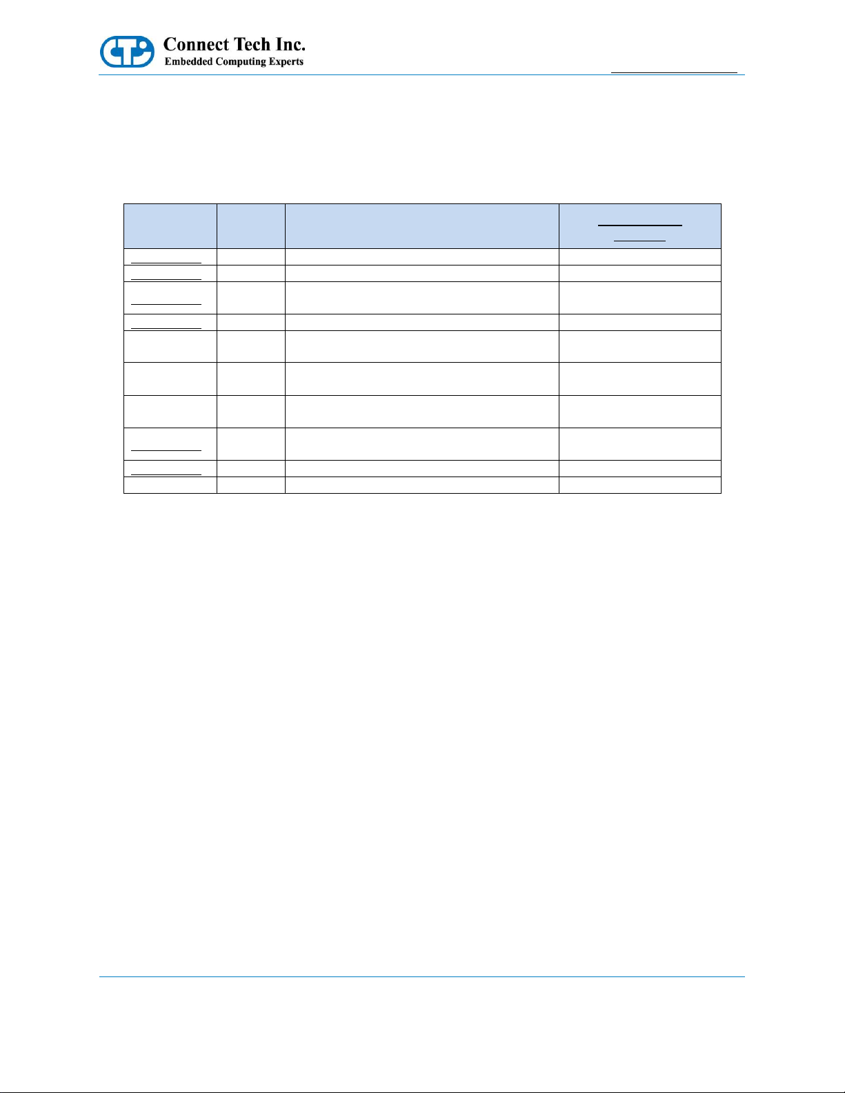
Cables
The following table summarizes the Elroy Carrier cables available.
Cable Kits
Drawing No.
Part No.
Description
Full Cable Kit
CKG059
CTIC-00430
CBG111
Dual DB9 Panel Mount to 10-Pin MiniTek
1
CTIC-00431
CBG112
Power Cable (Unterminated) to 6-Pin MiniTek
1
CTIC-00435
CBG116
System Cable (Unterminated) to 20-Pin
MiniTek
1
CTIC-00433
CBG117
RJ-45 Panel Mount to 10-Pin MiniTek
1
N/A
CBG160
Dual USB 3.0 to 20-pin RA USB3.0 Cable
Panel Mount: Right Angle Inner Exit
1
N/A
CBG287
Dual USB 3.0 to 20-pin RA USB3.0 Cable
Panel Mount: Right Angle Outer Exit
1
N/A
CBG288
Dual USB 3.0 to 20-pin RA USB3.0 Cable
Panel Mount: Vertical Exit
1
CTIC-00461
CBG145
HDMI Female Panel Mount to 20-Pin
MiniTek
1
CTIC-00571
MSG063
North American Power Supply Unit for Elroy
0
TBD
MSG071
Multi-Region Power Supply Unit for Elroy
0
 Loading...