

Page 1

Connect Tech Inc.
“Industrial Strength Communications”
Intellicon-NT960/PCI
Intelligent Serial Communications
Subsystem
User Manual
Connect Tech Inc
42 Arrow Road
Guelph, Ontario
N1K 1S6
Tel: 519-836-1291
800-426-8979
Fax: 519-836-4878
Email: sales@connecttech.com
URL: http://www.connecttech.com
CTIM-00008, Revision 0.02, January 7 2003
Part Number: MAN062
Intellicon-NT960/PCI User's Manual, ver. 0.02
Page 2

Intellicon-NT960/PCI User's Manual, ver. 0.02
Page 3

Warranty i
LIMITED WARRANTY
Connect Tech Inc. provides a Lifetime Warranty for all Connect
Tech Inc. products. Should this product, in Connect Tech Inc.'s
opinion, fail to be in good working order during the warranty
period, Connect Tech Inc. will, at its option, repair or replace this
product at no charge, provided that the product has not been
subjected to abuse, misuse, accident, disaster or non Connect
Tech Inc. authorized modification or repair.
You may obtain warranty service by delivering this product to an
authorized Connect Tech Inc. business partner or to Connect Tech
Inc. along with proof of purchase. Product returned to Connect
Tech Inc. must be pre-authorized by Connect Tech Inc. With an
RMA (Return Material Authorization) number marked on the
outside of the package and sent prepaid, insured and packaged for
safe shipment. Connect Tech Inc. will return this product by
prepaid ground shipment service.
The Connect Tech Inc. Lifetime Warranty is defined as the
serviceable life of the product. This is defined as the period during
which all components are available. Should the product prove to
be irreparable, Connect Tech Inc. reserves the right to substitute
an equivalent product if available or to retract Life Time Warranty
if no replacement is available.
The above warranty is the only warranty authorized by Connect
Tech Inc. Under no circumstances will connect tech inc. be liable
in any way for any damages, including any lost profits, lost
savings or other incidental or consequential damages arising out
of the use of, or inability to use, such product.
Intellicon-NT960/PCI User's Manual, ver. 0.02
Page 4

ii Copyright/Trademarks
Copyright Notice
The information contained in this document is subject to change
without notice. Connect Tech shall not be liable for errors
contained herein or for incidental consequential damages in
connection with the furnishing, performance, or use of this
material. This document contains proprietary information which
is protected by copyright. All rights are reserved. No part of this
document may be photocopied, reproduced, or translated to
another language without the prior written consent of Connect
Tech, Inc.
Copyright 2001, 2002 by Connect Tech, Inc.
Trademark Acknowledgment
Connect Tech, Inc. acknowledges all trademarks, registered
trademarks and/or copyrights referred to in this document as the
property of their respective owners.
Not listing all possible trademarks or copyright acknowledgments
does not constitute a lack of acknowledgment to the rightful
owners of the trademarks and copyrights mentioned in this
document.
Intellicon-NT960/PCI User's Manual, ver. 0.02
Page 5

FCC/DOC Certification iii
CLASS A COMPUTING DEVICE
Intellicon-NT960/PCI, ACM/16, ACM/Flex16, ACM/16RJ
FCC
This equipment complies with the requirements in Part 15 of FCC
Rules for a Class A computing device. Operation of this
equipment in a residential area may cause unacceptable
interference to radio and TV reception requiring the operator to
take whatever steps are necessary to correct the interference.
DOC/IC
This Class A digital apparatus meets all the requirements of the
Canadian Interference-Causing Equipment Regulations as defined
in ICES-003.
Cet appareil numérique de la classe A respecte toutes les
exigences du Règlement sur le matériel brouiller du Canada.
General
The above agency conformances were met by independent
laboratory testing of Connect Tech Inc. product(s) with shielded
cables, with metal hoods, attached to either the terminating
connectors or cable assemblies supplied with the product(s).
Failure to follow good EMC/EMI compliant cabling practices
may produce more emissions or less immunity than were
obtained in laboratory measurements.
Operation of this equipment in a residential area may cause
unacceptable interference to radio a TV reception, requiring the
user to take whatever steps necessary to correct the interference.
Intellicon-NT960/PCI User's Manual, ver. 0.02
Page 6

Intellicon-NT960/PCI User's Manual, ver. 0.02
Page 7

Contents v
Table of Contents
Chapter 1: Introduction
Introduction ........................................................................................... 1-1
Manual Overview.................................................................................. 1-2
Conventions & Symbols ..............................................................1-3
Product Overview.................................................................................. 1-4
Intellicon-NT960/PCI Host Adapter............................................ 1-4
Intellicon-NT960/PCI ACM/16 ................................................... 1-5
Intellicon-NT960/PCI ACM/16RJ............................................... 1-7
Intellicon-NT960/PCI ACM/Flex16 ............................................ 1-9
Intellicon-NT960/PCI Software................................................. 1-12
Customer Service Overview................................................................ 1-12
RMA Overview.......................................................................... 1-15
Chapter 2: Hardware Installation
Introduction ........................................................................................... 2-1
NT960/PCI Host Adapter............................................................. 2-1
Installing the NT960/PCI in your System...........................2-2
ACM/16, ACM/16RJ and ACM/Flex16 ...................................... 2-2
ACM/16/16RJ/Flex16 Address Selection........................... 2-3
SLIM Installation(ACM/Flex16)........................................ 2-6
SLIM Options..................................................................... 2-8
LED interface indicators (ACM/Flex16)............................ 2-8
ACM/16/16RJ/Flex16 to NT960/PCI Host Adapter........... 2-9
Chapter 3: Software Installation
Introduction ........................................................................................... 3-1
Intellicon-NT960/PCI User's Manual, ver. 0.02
Page 8

vi Contents
Chapter 4: Appendices
Appendix A: Specifications................................................................... 4-1
NT960/PCI Host Adapter............................................................. 4-1
NT960/PCI ACM/16, ACM/16RJ, ACM/Flex16.........................4-1
NT960/PCI Part Numbers............................................................ 4-3
Certification .................................................................................4-4
Appendix B: Connector Pinouts............................................................ 4-5
ACM/16 Pinouts ..........................................................................4-5
ACM/Flex16 Pinouts ...................................................................4-6
ACM/Flex16 SLIM Pinouts......................................................... 4-6
ACM/16RJ Pinouts ......................................................................4-9
Appendix C: RS-232 Option ...............................................................4-10
Installation .................................................................................4-11
LED interface indicators............................................................ 4-11
Appendix D: RS-485/422 Option ........................................................ 4-12
Introduction................................................................................ 4-12
Installation .................................................................................4-14
LED interface indicators............................................................ 4-14
Configuration options ................................................................4-15
RS-485/422 Cable Wiring.......................................................... 4-20
Appendix E: 20mA Current Loop Option ........................................... 4-22
Installation .................................................................................4-23
LED interface indicators............................................................ 4-23
20mA Current Loop................................................................... 4-24
Current Loop Cable Wiring .......................................................4-25
Processor ............................................................................4-1
Memory .............................................................................. 4-1
PCI Bus Interface ...............................................................4-1
Operating Environment ...................................................... 4-1
Power Requirements........................................................... 4-1
Dimensions......................................................................... 4-1
Asynchronous Communication Module .............................4-1
Operating Environment ...................................................... 4-2
Power Requirements........................................................... 4-2
Dimensions......................................................................... 4-2
Intellicon-NT960/PCI; ACM/16/Flex16/16RJ ...................4-4
FCC .................................................................. 4-4
DOC/IC ............................................................ 4-4
General ...............................................................................4-4
Line bias feature ............................................................... 4-17
Line load options.............................................................. 4-17
Intellicon-NT960/PCI User's Manual, ver. 0.02
Page 9

Contents vii
Chapter 4: Appendices (continued)
Appendix F: SLIM Insertion/Removal................................................ 4-26
ACM/Flex16 back cover removal.............................................. 4-27
SLIM insertion........................................................................... 4-28
SLIM removal............................................................................ 4-29
Appendix G: Factory Settings ............................................................. 4-30
NT960/PCI Host Adapter........................................................... 4-30
ACM/16, ACM/Flex16, ACM/16RJ Modules ........................... 4-31
ACM/16, ACM/Flex16, ACM/16RJ Address Setting ......4-31
ACM/Flex16: RS-485 SLIM options ...............................4-34
List of Tables
Table 1: ACM/16/Flex16/16RJ address settings ...................................2-5
Table 2: NT960/PCI SW1 switch settings........................................... 2-10
Table 3: DB-9 pinouts - ACM/16.......................................................... 4-5
Table 4: DB-9 pinouts - ACM/Flex16................................................... 4-6
Table 5: ACM/Flex16 SLIM pinouts.....................................................4-7
Table 5(continued): ACM/Flex16 SLIM pinouts ..................................4-8
Table 6: RJ-45 pinouts - ACM/16RJ..................................................... 4-9
Table 7: RS-485/422 SLIM; port/switch block relation ......................4-16
Table 8: RS-485/422 SLIM; line load options..................................... 4-16
Table 9: NT960/PCI SW1 factory settings.......................................... 4-30
Intellicon-NT960/PCI User's Manual, ver. 0.02
Page 10

viii Contents
List of Figures
Figure 1: NT960/PCI Host Adapter.......................................................1-5
Figure 2: ACM/16 module ....................................................................1-6
Figure 3: ACM/16RJ module ................................................................ 1-8
Figure 4: ACM/Flex16 module ...........................................................1-10
Figure 5: Intellicon-NT960/PCI - 32 port configuration......................1-11
Figure 6: Problem summary sheet....................................................... 1-13
Figure 7: ACM/16/Flex16 address switch block ................................... 2-3
Figure 8: ACM/16RJ address switch block........................................... 2-4
Figure 9: ACM/Flex16: SLIM socket locations .................................... 2-6
Figure 10: LED interface indicators (ACM/Flex16)..............................2-9
Figure 11: Connection of one ACM/16/16RJ/Flex16 module............. 2-13
Figure 12: Connection of three ACM/16/16RJ/Flex16 modules ......... 2-14
Figure 13: Connection of six ACM/16/16RJ/Flex16 modules.............2-15
Figure 14: RS-232 SLIM partial schematic......................................... 4-10
Figure 15: RS-485/422 SLIM partial schematic.................................. 4-13
Figure 16: RS-485/422 SLIM - DIP switches......................................4-15
Figure 17: Typical RS-485 circuit ....................................................... 4-17
Figure 18: RS-485/422 wiring diagram(8 wire) ..................................4-20
Figure 19: RS-485/422 wiring diagram(4 wire) ..................................4-20
Figure 20: RS-485/422 wiring diagram(2 wire) ..................................4-21
Figure 21: 20mA Current Loop partial schematic ............................... 4-22
Figure 22: Current Loop wiring diagram(4 wire)................................ 4-25
Figure 23: ACM/Flex16 back cover removal...................................... 4-27
Figure 24: SLIM insertion (ACM/Flex16) ..........................................4-28
Figure 25: SLIM removal (ACM/Flex16) ........................................... 4-29
Figure 26: ACM/16, ACM/Flex16 factory settings............................. 4-32
Figure 27: ACM/16RJ factory setting ................................................. 4-33
Figure 28: ACM/Flex16 RS-485 SLIM settings.................................. 4-34
Intellicon-NT960/PCI User's Manual, ver. 0.02
Page 11

Chapter 1: Introduction
Introduction ........................................................................................... 1-1
Manual Overview.................................................................................. 1-2
Conventions & Symbols ..............................................................1-3
Product Overview.................................................................................. 1-4
Intellicon-NT960/PCI Host Adapter............................................ 1-4
Intellicon-NT960/PCI ACM/16 ................................................... 1-5
Intellicon-NT960/PCI ACM/16RJ............................................... 1-7
Intellicon-NT960/PCI ACM/Flex16 ............................................ 1-9
Intellicon-NT960/PCI Software................................................. 1-12
Customer Service Overview................................................................ 1-12
RMA Overview.......................................................................... 1-15
Intellicon-NT960/PCI User's Manual, ver. 0.02
Page 12

Intellicon-NT960/PCI User's Manual, ver. 0.02
Page 13

Chapter 1: Introduction 1-1
Introduction
This section contains an overall description of the
Intellicon-NT960/PCI manual, the Intellicon-NT960/PCI product,
Connect Tech technical services, Return Merchandise
Authorization and warranty repair policies. The organization of
the information is as follows:
Manual Overview - describes the structure of the manual and
the conventions the manual uses.
Product Overview - describes the Intellicon-NT960/PCI, its
features and specifications.
Customer Services Overview - describes the various
customer support services available to users of Connect Tech
products.
RMA Overview - describes the RMA policy and procedures
for all Connect Tech products.
Intellicon-NT960/PCI User's Manual, ver. 0.02
Page 14

1-2 Chapter 1: Introduction
Manual Overview
The purpose of the Intellicon-NT960/PCI User's Manual is to help
you install the Intellicon-NT960/PCI subsystem as effortlessly as
possible. The manual includes four main sections:
Introduction - the section you are currently reading, covers
the Intellicon-NT960/PCI features; Connect Tech's customer
services; and return merchandise authorization (RMA)
policies and procedures.
Hardware Installation - describes installation of the
Intellicon-NT960/PCI host adapter and the IntelliconNT960/PCI ACM/16, ACM/16RJ and ACM/Flex16 external
modules.
Software Installation - discusses the installation of the
Intellicon-NT960/PCI device drivers under various operating
systems.
Note:
We recommend that you read both the Hardware
Installation and Software Installation sections before you
attempt to install the Intellicon-NT960/PCI.
Appendices - the appendices contain information on
electrical pinouts, product specifications such as power
requirements; and other technical information.
Intellicon-NT960/PCI User's Manual, ver. 0.02
Page 15
Chapter 1: Introduction 1-3
Conventions & Symbols
This manual uses the following conventions:
In most cases the font for file names and command
statements is 9 point Arial Narrow Bold. An example is:
DEVICE=NT960.SYS a=D000 p=300 n=1 i=3 d=COM
Note: the "Note" convention informs you of important
messages, exceptions, or special cases.
Example: the "Example" convention outlines hardware
and software installation examples.
Technical Tip: the "Technical Tip" convention offers
technical tips to assist you in hardware and software
installation or problems.
WARNING
The "Warning" convention advises you to take certain
precautions in order to avoid possible damage to your
Connect Tech product.
This message warns you that your Connect Tech product is
very sensitive to static electricity. Make sure that before
you handle the product you practice proper ESD
procedures.
Intellicon-NT960/PCI User's Manual, ver. 0.02
Page 16

1-4 Chapter 1: Introduction
Product Overview
The Intellicon-NT960/PCI is a high performance intelligent
multi-port subsystem that allows you to connect up to 128 serial
devices through one expansion slot.
The Intellicon-NT960/PCI subsystem consists of the following
components:
Intellicon-NT960/PCI Host Adapter
Intellicon-NT960/PCI ACM/16, ACM/16RJ or ACM/Flex16,
power supply, and bus cable
Intellicon-NT960/PCI Device Drivers
Intellicon-NT960/PCI Host Adapter
The NT960/PCI Host Adapter provides the high-speed interface
between a host computer and an external ACM/16, ACM/16RJ or
ACM/Flex16 communication module. The NT960/PCI Host
Adapter off loads from the host computer the task of managing
the serial communication component of an application. The
Intellicon-NT960/PCI Host Adapter includes features such as:
Connects up to eight ACM/16, ACM/16RJ and/or
ACM/Flex16 modules giving you a total of 128 asynchronous
RS-232 and/or RS-485/422 and/or 20mA Current Loop serial
ports out of one slot.
1MB of dual ported SRAM for data and program storage.
System requirements are one 3.3V, 5V or universal PCI bus
compatible expansion slot; one available interrupt, one
available 2MB memory segment which is assigned by the
Plug and Play system.
Intellicon-NT960/PCI User's Manual, ver. 0.02
Page 17
Chapter 1: Introduction 1-5
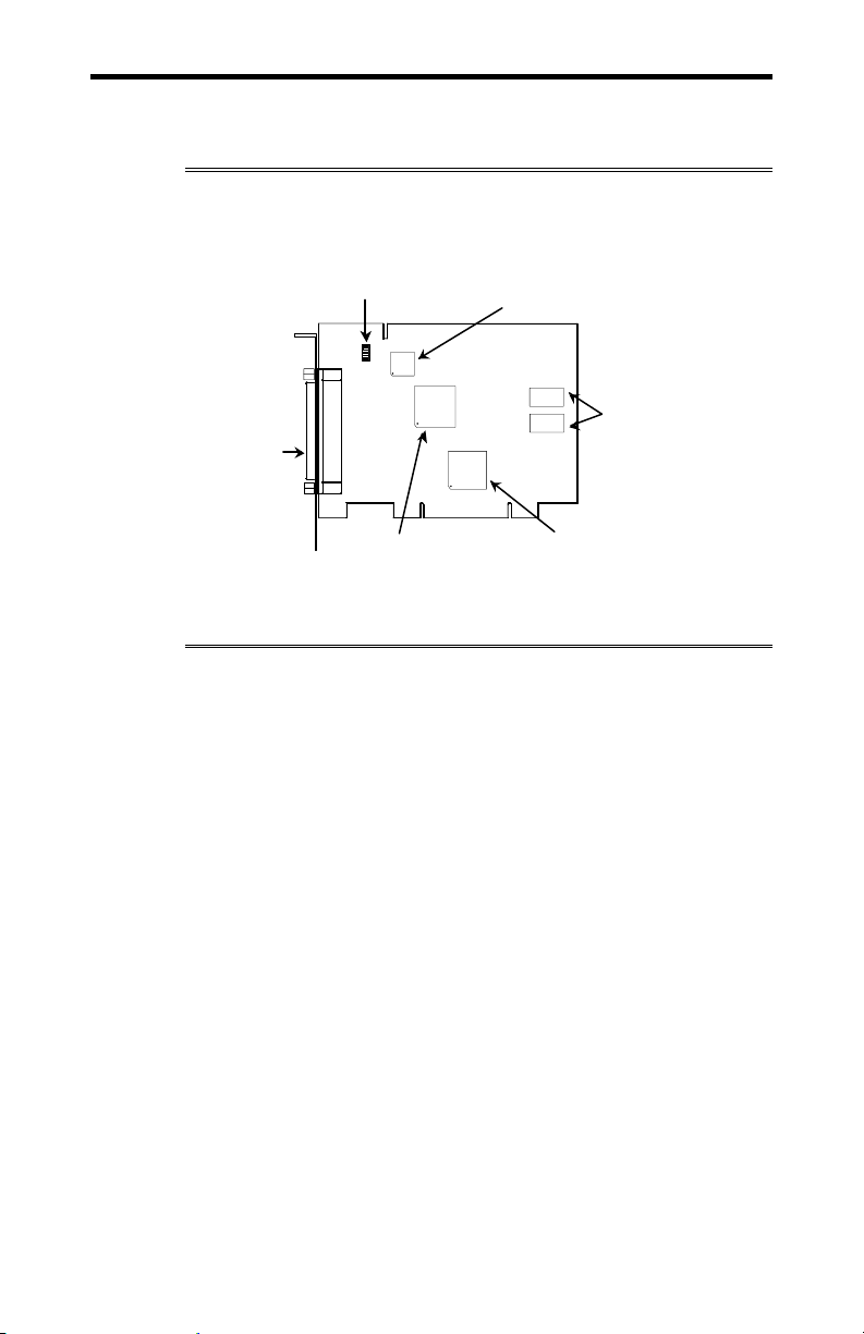
Figure 1 shows the locations of various hardware components of
the NT960/PCI Host Adapter.
Figure 1: NT960/PCI Host Adapter
DIP Sw itch SW1
P3P3
DB3 7
Connector
Intel i960 Processor
CPLD
1MB SRAM
PCI Bridge
Intellicon-NT960/PCI ACM/16
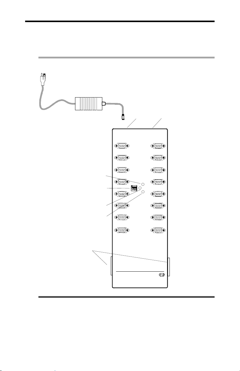
The ACM/16 (Asynchronous Communication Module) is an
external module that connects to the NT960/PCI Host Adapter via
a high speed 37 pin external bus cable. Figure 2 shows a top
view of the ACM/16. The ACM/16 offers the following features:
16 asynchronous RS-232-C serial ports.
Four CLCD1400 RISC-like quad UARTS c/w 12 bytes of
receive and 12 bytes of transmit FIFO for each port.
Each port is individually programmable for baud rates up to
115 Kbps.
Each RS-232 port supports the following signals: TxD, RxD,
DTR, DSR, RTS, CTS, DCD, RI.
Support for 5 to 8 data bits per character plus optional parity;
odd, even, no or forced parity; and 1 or 2 Stop Bits.
Includes a 37 pin bus cable and an external power supply.
Intellicon-NT960/PCI User's Manual, ver. 0.02
Page 18
1-6 Chapter 1: Introduction
A
A
Up to eight ACM/16's, ACM/16RJ’s and/or ACM/Flex16’s
can connect to an Intellicon-NT960/PCI Host Adapter
providing up to 128 serial ports.
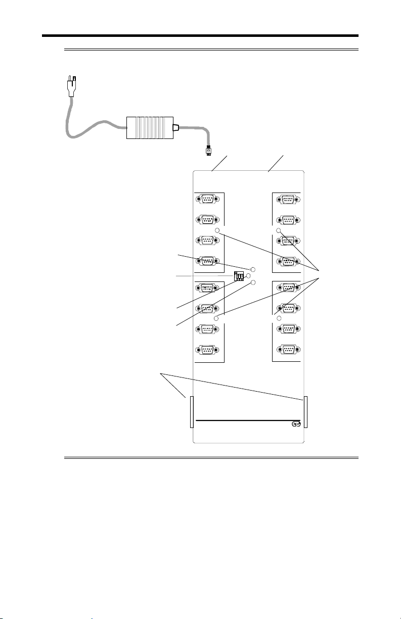
Figure 2: ACM/16 module
External power supply
Power LED
CM/16 address switch
ctivity LED
Traffic LED
DB37 bus connector
Power in
connector connector
1
2
5
6
Addr e ss
9
10
13
14
Intellicon-NT960 ACM/16
Connect Tech Inc.
Activity
Power
Traffic
Power out
3
4
7
8
11
12
15
16
Intellicon-NT960/PCI User's Manual, ver. 0.02
Page 19

Chapter 1: Introduction 1-7
Intellicon-NT960/PCI ACM/16RJ
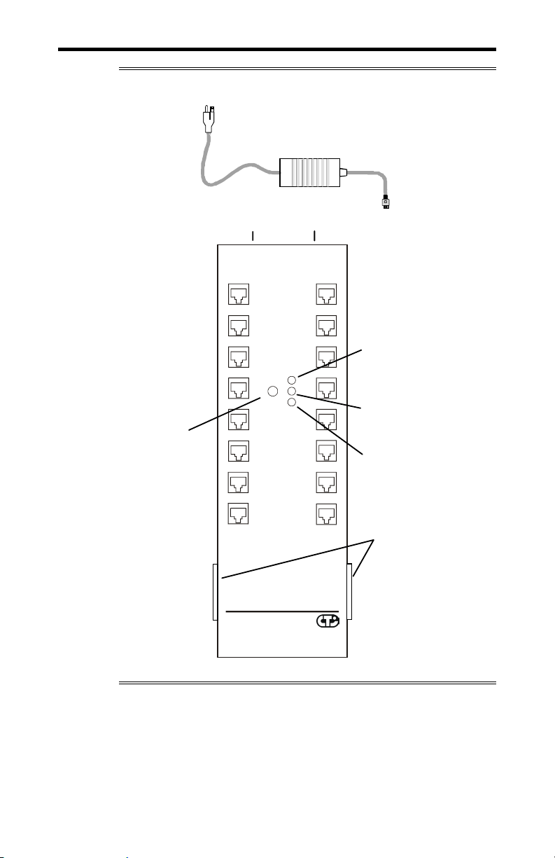
The ACM/16RJ (Asynchronous Communication Module) is an
external module that connects to the NT960/PCI Host Adapter via
a high speed 37 pin external bus cable. Figure 3 shows a top
view of the ACM/16RJ. The ACM/16RJ offers the following
features:
16 asynchronous RS-232-C serial ports
16 RJ-45 (8 pin) connectors
Four CLCD1400 RISC-like quad UARTS c/w 12 bytes of
receive and 12 bytes of transmit FIFO for each port.
Each port is individually programmable for baud rates up to
115 Kbps.
Each RS-232 port supports the following signals: TxD, RxD,
DTR, RTS, CTS, DCD.
Support for 5 to 8 data bits per character plus optional parity;
odd, even, no or forced parity; and 1 or 2 Stop Bits.
Includes a 37 pin bus cable and an external power supply.
Up to eight ACM/16's, ACM/16RJ’s and/or ACM/Flex16’s
can connect to an Intellicon-NT960/PCI Host Adapter
providing up to 128 serial ports.
Intellicon-NT960/PCI User's Manual, ver. 0.02
Page 20
1-8 Chapter 1: Introduction
A
A
Figure 3: ACM/16RJ module
power supply
External
ACM/16RJ
Address switch
Power-in
connector
PWR-IN PWR-OUT
1
2
57
6
911
10 12
13
14 16
Intellicon NT960 ACM/16RJ
Connect Tech Inc
7
8
ddress
1
2
456
Power-out
connector
Power
ctivity
3
Traffic
3
4
8
15
bus connector
Power LED
Activity LED
Traffic LED
DB37
Intellicon-NT960/PCI User's Manual, ver. 0.02
Page 21

Chapter 1: Introduction 1-9
Intellicon-NT960/PCI ACM/Flex16
The ACM/Flex16 (Asynchronous Communication Module) is an
external module that connects to the NT960/PCI Host Adapter via
a high speed 37 pin external bus cable. Figure 4 shows a top
view of the ACM/Flex16. The ACM/Flex16 offers the following
features:
16 asynchronous RS-232-C and/or RS-485/422 and/or 20mA
Current Loop serial ports
The RS-232, RS-485/422 and 20mA Current Loop electrical
interfaces are on field upgradeable Serial Line Interface
Modules (SLIM). This allows you to run different line
interfaces on the ACM/Flex16 at the same time.
Four CLCD1400 RISC-like quad UARTS c/w 12 bytes of
receive and 12 bytes of transmit FIFO for each port.
Each port is individually programmable for baud rates up to
115 Kbps.
Each RS-232 port supports the following signals: TxD, RxD,
DTR, DSR, RTS, CTS, DCD, RI.
Note: ports 3, 4, 7, 8, 11, 12, 15 and 16 do not support the
RI signal.
Each RS-485/422 port supports the following signals: TxD,
RxD, RTS, CTS.
Each 20mA Current Loop port supports the following signals:
TxD, RxD.
Support for 5 to 8 data bits per character plus optional parity;
odd, even, no or forced parity; and 1 or 2 Stop Bits.
Includes a 37 pin bus cable and an external power supply.
Up to eight ACM/16's, ACM/16RJ’s and/or ACM/Flex16’s
can connect to an Intellicon-NT960/PCI Host Adapter
providing up to 128 serial ports.
Intellicon-NT960/PCI User's Manual, ver. 0.02
Page 22
1-10 Chapter 1: Introduction
A
A
r
Figure 4: ACM/Flex16 module
External power supply
Power LED
CM/16 address switch
ctivity LED
Traffic LED
DB37 bus connecto
Power out
Power in
Power
Activity
Traffic
connector
SLIM
Type
SLIM
Type
16
15
14
13
12
11
10
9
Interface LED
connector
1
SLIM
2
Type
3
4
Address
5
SLIM
6
Type
7
8
Intellicon NT960
Connect Tech Inc.
ACM/Flex16
Intellicon-NT960/PCI User's Manual, ver. 0.02
Page 23
Chapter 1: Introduction 1-11
The Intellicon-NT960/PCI subsystem can accommodate both
small and large multi-channel applications. The NT960/PCI Host
Adapter can connect up to eight ACM/16, ACM/16RJ and/or
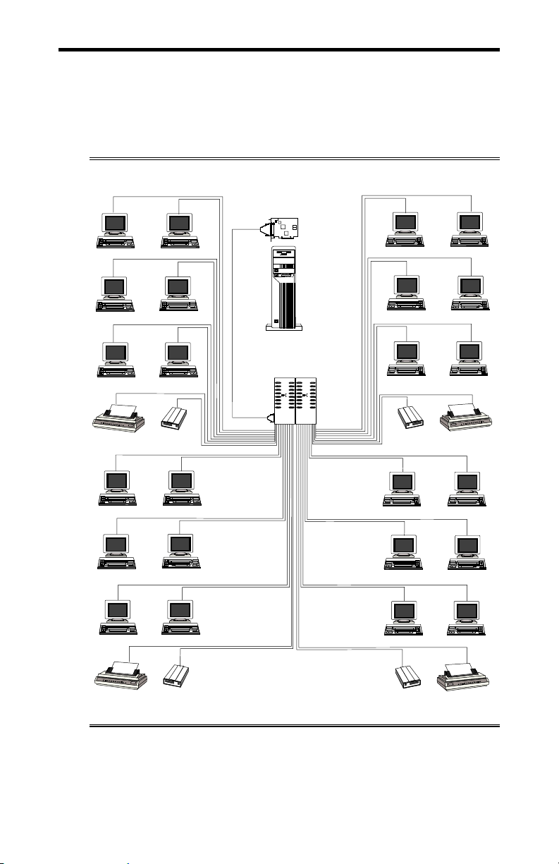
ACM/Flex16 modules for a total of 128 ports. Figure 5 below
represents a sample configuration for a system requiring 32 ports.
Figure 5: Intellicon-NT960/PCI - 32 port configuration
Terminals
NT960/PCI
Host Adapter
Terminals
Printer
Terminals
Terminals
Terminals
Terminals
Terminals
Modem
Terminals
Host Computer
Terminals
ACM/16, ACM16RJ
or ACM/Flex16 I/O Modules
Modem
Terminals
Terminals
Printer
Terminals
Printer
Modem
Modem
Printer
Intellicon-NT960/PCI User's Manual, ver. 0.02
Page 24

1-12 Chapter 1: Introduction
Intellicon-NT960/PCI Software
The NT960/PCI ships with software device drivers. These device
drivers provide support for multi-port serial communications with
different operating systems without the need for programming.
See Chapter 3: Software Installation for driver installation
instructions for the different operating systems.
Customer Service Overview
If you experience difficulties after reading the manual and using
the product, contact the Connect Tech reseller from which you
purchased the product. In most cases the reseller can help you
with product installation and difficulties.
In the event that the reseller is unable to resolve your problem, our
highly qualified support staff can assist you. Please refer to and
complete the problem summary sheet found in Figure 6 before
contacting us.
Intellicon-NT960/PCI User's Manual, ver. 0.02
Page 25

Chapter 1: Introduction 1-13
Figure 6: Problem summary sheet
Problem Description
Connect Tech Product Description
Product: Revision no.:
Product serial no.: No. of serial ports:
IRQ selected: Base address selected:
I/O port address selected:
Device driver: Revision no.:
System Description
Operating system: Revision no.:
System type & manufacturer:
Amount of RAM: CPU type/speed:
Video adapter: Settings:
Network adapter: Settings:
Hard disk adapter: Settings:
Tape adapter: Settings:
Other serial adapters Settings:
Other adapters: Settings:
Devices connected to ports:
Intellicon-NT960/PCI User's Manual, ver. 0.02
Page 26

1-14 Chapter 1: Introduction
We offer several ways for you to contact us:
Mail/Courier
You may contact us by letter and our mailing address for
correspondence is:
Connect Tech Inc.
c/o Customer Service
42 Arrow Road
Guelph, Ontario
Canada N1K 1S6
Email/Internet
You may contact us through the Internet. Our email and URL
addresses on the Internet are:
sales@connecttech.com
support@connecttech.com
www.connecttech.com
Note:
1. You can submit your technical support questions to our
customer support engineers via our Internet email address
OR
2. You can refer to our knowledge database found in the
Customer Support section of our World Wide Web site.
OR
3. You can fill out the problem summary form, found in the
Customer Support section of our World Wide Web site and
submit it to our customer support engineers via the Web.
OR
4. You can obtain the latest versions of software drivers and
manuals from the Customer Support section of our World
Wide Web site.
Telephone/Facsimile
Customer Support representatives are ready to answer your call
Monday through Friday, from 9:00 a.m. to noon and 1:00 p.m. to
5:00 p.m. Eastern Standard Time. Our numbers for calls are:
Telephone: 519-836-1291
Toll free: 800-426-8979
Facsimile 519-836-4878 (on-line 24 hours)
Intellicon-NT960/PCI User's Manual, ver. 0.02
Page 27

Chapter 1: Introduction 1-15
RMA Overview
Connect Tech products requiring warranty or non warranty repairs
need an RMA number. To obtain a Return Merchandise
Authorization (RMA) Number please contact us in the following
manner:
Go to the RMA Request Form found in the Support Center on our
website:
www.connecttech.com
Telephone, fax, email or mail us at:
Connect Tech Inc.
Technical Support
42 Arrow Road
Guelph, Ontario
Canada N1K 1S6
Phone: 519-836-1291
800-426-8979
Facsimile: 519-836-4878
Email: support@connecttech.com
Include with the product, proof of purchase (including date of
purchase), a description of the problem and the RMA number.
Clearly display the RMA number on the external packaging.
Please refer to the Limited Warranty for further restrictions or
requirements.
The NT960/PCI Host Adapter is very sensitive to static electricity.
Make sure that before you remove the card from your computer,
you wear an anti-static wristband. When you remove the board
from your computer, handle it only by the edges and place it on
the anti-static bag or an anti-static mat.
Note:
1. Please pack the item for repair securely and ship it prepaid
and insured. Connect Tech is not liable for damage or loss
to the product due to shipping.
2. Connect Tech will not accept items for repair without an
RMA number.
3. Connect Tech will not accept items for repair shipped freight
collect.
Intellicon-NT960/PCI User's Manual, ver. 0.02
Page 28

Intellicon-NT960/PCI User's Manual, ver. 0.02 Intellicon-NT960/PCI User's Manual, ver. 0.02
Page 29

Chapter 2: Hardware Installation
Introduction ........................................................................................... 2-1
NT960/PCI Host Adapter............................................................. 2-1
Installing the NT960/PCI in your System...........................2-2
ACM/16, ACM/16RJ and ACM/Flex16 ...................................... 2-2
ACM/16/16RJ/Flex16 Address Selection........................... 2-3
SLIM Installation(ACM/Flex16)........................................ 2-6
SLIM Options..................................................................... 2-8
LED interface indicators (ACM/Flex16)............................ 2-8
ACM/16/16RJ/Flex16 to NT960/PCI Host Adapter........... 2-9
Page 30

Intellicon-NT960/PCI User's Manual, ver. 0.02
Page 31

Chapter 2: Hardware Installation 2-1
Introduction
Hardware installation involves configuration of the following:
The NT960/PCI Host Adapter
One or more ACM/16, ACM/16RJ or ACM/Flex16 external
modules
NT960/PCI Host Adapter
Installation of the NT960/PCI Host Adapter consists of:
1. Installing the Host Adapter in your computer.
2. Connecting one or more ACM/16, ACM/16RJ or
ACM/Flex16 external modules.
You must configure the various settings before installing the Host
Adapter in the computer. In order to insure a successful
installation, please follow the steps in the order specified above.
The NT960/PCI Host Adapter is very sensitive to static electricity.
Make sure that before you remove the card from the anti-static
shipping bag, you wear an anti-static wristband. When you
remove the board from the anti-static bag, handle it only by the
edges and place it on the anti-static bag or an anti-static mat.
Intellicon-NT960/PCI User's Manual, ver. 0.02
Page 32

2-2 Chapter 2: Hardware Installation
Installing the NT960/PCI in your System
To install the NT960/PCI Host Adapter in your computer follow
these steps:
Computer components are very sensitive to static electricity.
When installing adapters in your computer make sure that you
wear an anti-static wristband. Handle the adapter by its edges
and place it on the anti-static bag or an anti-static mat.
1. Turn the power off to your computer.
2. Open your computer to expose the expansion slots (consult
the system documentation for information on this procedure.)
3. Choose an available PCI expansion slot.
4. Remove the screw and the expansion slot cover from the slot
you select and save both.
5. Place the NT960/PCI in the expansion slot and push down
gently until the card seats fully in the slot.
Note: Do not force the card into the expansion slot. If you meet a
great deal of resistance, remove the board and try again.
6. Align the mounting bracket and secure the board with the
screw that you saved.
7. Close your computer.
ACM/16, ACM/16RJ and ACM/Flex16
The installation of an ACM/16, ACM/16RJ or ACM/Flex16
external module consists of:
1. Setting the ACM/16, ACM/16RJ or ACM/Flex16 address
number
2. Installing the Serial Line Interface Modules (SLIMs) in the
ACM/Flex16
3. Connecting one or more ACM/16, ACM/16RJ or
ACM/Flex16 modules to the NT960/PCI Host Adapter
To insure a successful installation, you must configure the
appropriate settings and follow the steps in the order specified.
Intellicon-NT960/PCI User's Manual, ver. 0.02
Page 33
Chapter 2: Hardware Installation 2-3
M
A
M
ACM/16/16RJ/Flex16Address Selection
The ACM/16, ACM/Flex16 and ACM/16RJ address switch block
or switch assigns a number for each port on the ACM/16,
ACM/16RJ and ACM/Flex16. This switch setting enables the
Host Adapter to identify each port. You must set each ACM/16,
ACM/Flex16 or ACM/16RJ connected to a NT960/PCI Host
Adapter for an unique address. Please refer to Figures 7 and 8
for the location and orientation of the ACM/16, ACM/Flex16 and
ACM/16RJ address switch block or switch.
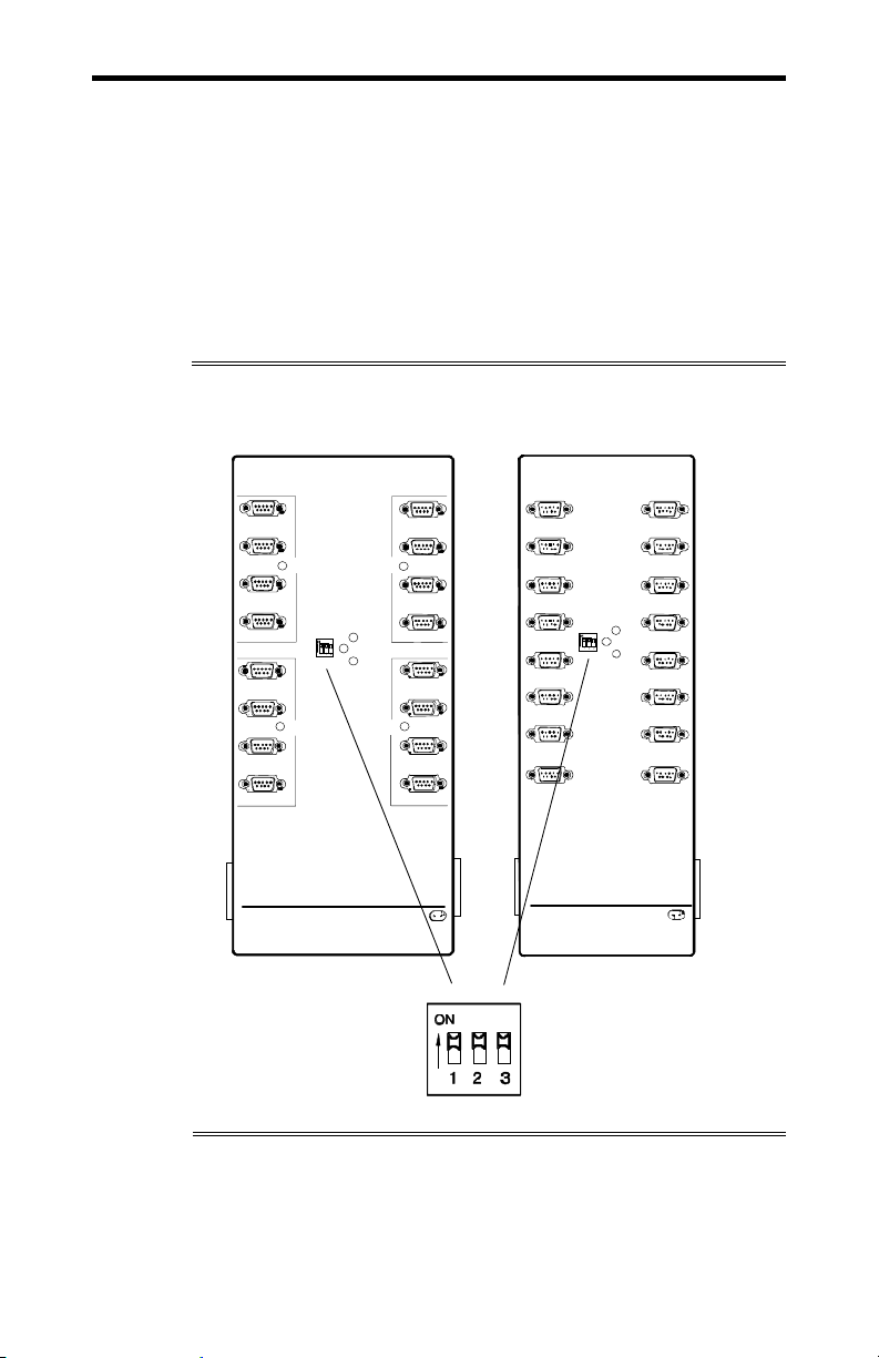
Figure 7: ACM/16/Flex16 address switch block
ACM/Flex16 ACM/16
1
SLI
2
Type
3
4
5
6
7
89
Intellicon NT960 ACM/Flex16
Connect Tech Inc.
Activity
Address
SLIM
Type
16
15
SLI
Type
14
Powe
13
Traffic
12
SLIM
11
Type
10
ddress
1
2
5
6
9
10
13
14
Intellicon-NT960 ACM/ 16
Connect Tech Inc.
0
1
Address
Activity
3
4
7
Power
8
Traffic
11
12
15
16
Intellicon-NT960/PCI User's Manual, ver. 0.02
Page 34

2-4 Chapter 2: Hardware Installation
Figure 8: ACM/16RJ address switch block
ACM/16RJ
PWR-IN PWR-OUT
1
2
5
1
8
7
6
5
6
Address
9
10 12
13 15
14 16
Intellicon NT960
Connect Tech Inc
1
8
7
6
5
Address
3
4
7
Power
2
3
Activity
4
8
Traffic
11
ACM/16RJ
2
3
4
The ACM/16, ACM/Flex16 and ACM/16RJ ship with the address
switch block or switch set for address 1, which assigns numbers 1
through 16 to the serial ports. If you are connecting only one
ACM/16, ACM/16RJ or ACM/Flex16 to the Host Adapter then
use this setting. If you are connecting more than one then
configure each ACM/16, ACM/16RJ or ACM/Flex16 with an
unique address. Table 1 outlines all the switch settings for the
address switch block and their corresponding address and port
numbers.
Intellicon-NT960/PCI User's Manual, ver. 0.02
Page 35

Chapter 2: Hardware Installation 2-5
A
A
WARNING
Do not use a pencil to set the DIP switches as the lead graphite
may short-circuit the switch.
Table 1: ACM/16/Flex16/16RJ address settings
Address Port numbers
1 2 3
1 1 - 16 1 on on on
2 17 - 32 2 off on on
3 33 - 48 3 on off on
4 49 - 64 4 off off on
5 65 - 80 5 on on off
6 81 - 96 6 off on off
7 97 - 112 7 on off off
8 113 - 128 8 off off off
assigned
Example:
The following examples show the ACM/16, ACM/Flex16 or
ACM/16RJ address switch block or switch set for:
Address 1, ports 1 through 16(default):
ACM/16/Flex16
ddress
Address 2, ports 17 through 32:
ACM/16/Flex16
ddress
ACM/16RJ
Switch settings
0
1
0
1
ACM/16/Flex16
DIP Switch settings
ACM/16RJ
1
8
7
6
ACM/16RJ
8
7
6
5
Address
1
5
Address
2
3
4
2
3
4
Intellicon-NT960/PCI User's Manual, ver. 0.02
Page 36

2-6 Chapter 2: Hardware Installation
SLIM Installation(ACM/Flex16)
The ACM/Flex16 module has four 72 pin SLIM sockets that
accept line transceiver modules. Each transceiver module
provides the RS-232 or RS-485/422 or 20mA Current Loop
receivers and transmitters to condition four serial ports. SLIM 1
interfaces ports 1, 2, 3, 4; SLIM 2 interfaces ports 5, 6, 7, 8; SLIM
3 interfaces ports 9, 10, 11, 12; and SLIM 4 interfaces ports 13,
14, 15, 16. Refer to Figure 9 for the location and orientation of
the SLIM sockets on the ACM/Flex16
Figure 9: ACM/Flex16: SLIM socket locations
(view from back with cover removed)
ACM/Flex16
SLIM 4 socket
(SM4)
SLIM 3 socket
(SM3)
SLIM 1 socket
(SM1)
SLIM 2 socket
(SM2)
Intellicon-NT960/PCI User's Manual, ver. 0.02
Page 37

Chapter 2: Hardware Installation 2-7
To insert a SLIM into a connector follow these steps:
1. Place the SLIM into the socket almost vertically (about 75degree angle), making sure that it is properly oriented and
fully inserted into the socket.
2. Press downward and sideways on the SLIM until it latches
into the socket. Do NOT force the SLIM, the installation
process requires a small force and should be very smooth and
easy. If you encounter resistance then re-check the orientation
and insertion depth. Refer to Appendix F: SLIM
Insertion/Removal regarding the removal of the
ACM/Flex16 back cover and the insertion of a SLIM.
To remove a SLIM from a connector follow these steps:
1. Using both hands, place your thumbs on the metal clips that
hold the SLIM into the socket, and place your index fingers
on the edge of the SLIM.
2. Push outwards (with your thumbs) on the metal clips until the
SLIM is released from the clips. Your index fingers can then
raise the SLIM past the clips. The SLIM is then free to be
removed from the ACM/Flex16 board. The force required to
open the metal clips is small and the SLIM naturally springs
upwards as soon as the clips are open wide enough. If
removal is difficult, then you are probably trying to raise the
SLIM before the clips are open. Refer to Appendix F:
SLIM Insertion/Removal regarding the removal of the
ACM/Flex16 back cover and the removal of a SLIM.
The RS-232, RS-485/422 and 20mA Current Loop SLIMs are very
sensitive to static electricity. Make sure that before you remove
the SLIMs from the anti-static shipping bag, you wear an antistatic wristband. When you remove the board from the anti-static
bag, handle it only by the edges and place it on the anti-static bag
or an anti-static mat.
Intellicon-NT960/PCI User's Manual, ver. 0.02
Page 38

2-8 Chapter 2: Hardware Installation
SLIM Options
The ACM/Flex16 has four SLIM sockets to accept Connect
Tech's RS-232 and/or RS-485/422 and/or 20mA Current Loop
Serial Line Interface Modules (SLIM). If you order RS-232
modules please refer to Appendix C: RS-232 Option for more
technical information. If you order RS-485/422 modules please
refer to Appendix D: RS-485/422 Option for more technical
information. If you order 20mA Current Loop modules please
refer to Appendix E: 20mA Current Loop Option for more
technical information.
LED interface indicators (ACM/Flex16)
You can install RS-232 and/or RS-485/422 and/or 20mA Current
Loop Serial Line Interface Modules in your ACM/Flex 16. The
ACM/Flex16 has LED indicators on its front panel to show you
the electrical interface in use for a specific group of four ports.
When the LED is red the RS-485/422 interface is in use; when it
is green the RS-232 interface is in use; and when it is amber the
20mA Current Loop interface is in use. Please refer to Figure 10
for the location of these LED interface indicators.
Intellicon-NT960/PCI User's Manual, ver. 0.02
Page 39

Chapter 2: Hardware Installation 2-9
Figure 10: LED interface indicators (ACM/Flex16)
ACM/Flex16
1
2
SLIM
Type
3
4
Address
5
6
SLIM
Type
7
8 9
Intellicon NT960 ACM/Flex16
Connect Tech Inc.
Power
Activity
Traffic
16
15
SLIM
Type
14
13
12
SLIM
11
Type
10
LEDs to indicate the electrical interface
in use for specific groups of four ports.
where:
red = RS-485
green = RS-232
amber = 20mA Current Loop
Note: The Serial Line Interface Modules control four ports, and
therefore the LED indicators show the electrical interface in use
for four ports.
ACM/16/16RJ/Flex16 to NT960/PCI Host Adapter
The NT960/PCI was designed to be compatible with existing
ACM setups, as well as to improve the performance of these and
other new installations. You can achieve this performance
improvement by setting switch 6 on DIP switch block SW1 on the
NT960/PCI Host Adapter and by using a new bus cable assembly.
Please refer to Figure 1 for the location of DIP switch block
SW1.
Intellicon-NT960/PCI User's Manual, ver. 0.02
Page 40

2-10 Chapter 2: Hardware Installation
The following table shows appropriate settings for DIP switch
block SW1 for various ACM configurations.
Table 2: NT960/PCI SW1 switch settings
Switch Position Configuration
ON
1 2 3 4 5
SW1
ON
Switch 6 on DIP switch block SW1 set
One to 8 ACM modules stacked together,
with only one bus cable between the
6
NT960/PCI Host adapter and the first ACM
module.
Switch 6 on DIP switch block SW1 set
Any number of ACM modules with 2 bus
on.
off.
cables (one cable between the NT960/PCI
1 2 3 4 5
SW1
Host adapter and the first ACM, and then
6
another cable somewhere between the first
ACM and last ACM).
The steps to connect ACM/16, ACM/16RJ and ACM/Flex16
external modules to a NT960/PCI Host Adapter are:
1. Turn off or disconnect the power to the computer containing
the NT960/PCI Host Adapter.
2. Connect the ACM/16, ACM/16RJ or ACM/Flex16 to the
NT960/PCI Host Adapter with the DB37 bus cable supplied.
3. If you are connecting more than one ACM/16, ACM/16RJ or
and/or ACM/Flex16 to the Host Adapter, verify that each
module has a unique address switch setting.
4. The NT960/PCI Host Adapter can connect up to a maximum
of eight ACM/16, ACM/16RJ and/or ACM/Flex16 modules
giving you a total of 128 ports. You can connect the modules
directly to each other. When connecting the modules to each
other please attach metal straps between each module.
5. After you connect the ACM/16, ACM/16RJ and/or
ACM/Flex16 modules to the Host Adapter and to each other,
connect the ACM/16, ACM/16RJ or ACM/Flex16 power
supply to the module and then plug it into your power source.
Intellicon-NT960/PCI User's Manual, ver. 0.02
Page 41

Chapter 2: Hardware Installation 2-11
Note:
1. If an existing installation has a two cable configuration, we
recommend that you replace the cables with the newer cable
assembly.
2. You should use no more than two bus cables for the entire
subsystem.
Note:
The ACM/16 and ACM/16RJ require the connection of only
one external power supply for every 48 ports connected to a
HOST Adapter. Please connect the power supply to the POWER
IN connector on the first ACM/16 or ACM/16RJ module (16
ports) and then connect power cables between the POWER OUT
and the POWER IN connectors on the ACM/16 or ACM/16RJ
modules.
When you add another ACM/16 or ACM/16RJ module to bring
the total to 64 ports you must connect another external NT960
power supply to the POWER IN connector on this additional
ACM/16 orACM/16RJ module. If you add another 32 ports to
bring the total to 96 ports you can once again connect power
cables between the POWER OUT and POWER IN connectors on
the ACM/16 or ACM/16RJ modules. Please refer to Figures 11,
12 and 13 for connecting multiple ACM/16, ACM/16RJ or
ACM/Flex16 modules.
Intellicon-NT960/PCI User's Manual, ver. 0.02
Page 42

2-12 Chapter 2: Hardware Installation
Note:
The ACM/Flex16 with RS-232 and/or 20mA interfaces only
requires the connection of one external power supply for every
48 ports connected to a HOST Adapter.
The ACM/Flex16 with RS-485 only or a combination of RS-232
and RS-485 and 20mA Current Loop interfaces requires the
connection of one external power supply for every 32 ports
connected to a HOST Adapter.
Please connect the power supply to the POWER IN connector on
the first ACM/Flex16 (or ACM/16/16RJ) module (16 ports) and
then connect power cables between the POWER OUT and the
POWER IN connectors on the ACM/16, ACM/16RJ and
ACM/Flex16 modules.
When you add another ACM/Flex16 or ACM/16 or ACM/16RJ
module to bring the total to 48 ports you must connect another
external NT960 power supply to the POWER IN connector on
this additional ACM/Flex16, ACM/16 or ACM/16RJ module. If
you add another 16 ports to bring the total to 64 ports you can
once again connect power cables between the POWER OUT and
POWER IN connectors on the ACM/Flex16, ACM/16 or
ACM/16RJ modules. Please refer to Figures 11, 12 and 13 for
connecting multiple ACM/16/16RJ/ modules.
6. Turn on or connect the power to your host computer.
WARNING
1. When connecting or disconnecting an ACM/16, ACM/16RJ
or ACM/Flex16 to a NT960/PCI Host Adapter or to another
ACM/16, ACM/16RJ or ACM/Flex16 module, you must turn
off or disconnect the computer's power supply and the
power supply to the ACM/16, ACM/16RJ or ACM/Flex16
module(s). Failure to observe this precaution will result in
damage to the NT960/PCI Host Adapter, ACM/16,
ACM/16RJ or ACM/Flex16.
2. You can connect only ACM/16, ACM/16RJ or ACM/Flex16
modules to a NT960/PCI Host Adapter or to another
ACM/16, ACM/16RJ or ACM/Flex16 module. Failure to
observe this precaution will result in damage to the
NT960/PCI Host Adapter, ACM/16, ACM/16RJ or
ACM/Flex16.
Intellicon-NT960/PCI User's Manual, ver. 0.02
Page 43

Chapter 2: Hardware Installation 2-13
A
Figures 11, 12 and 13 show different methods of connecting
ACM/16, ACM/16RJ or ACM/Flex16 modules to the NT960/PCI
Host Adapter.
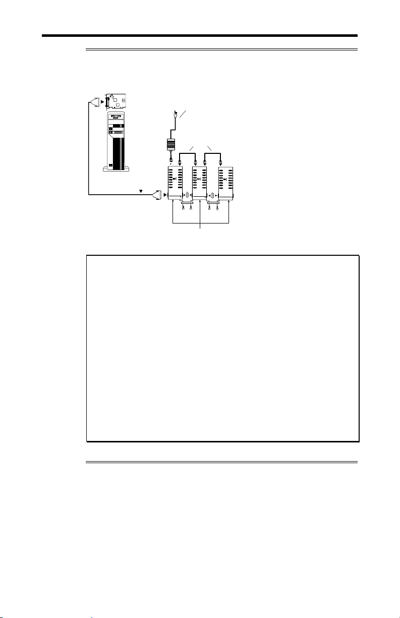
Figure 11: Connection of one ACM/16/16RJ/Flex16 module
NT960/PCI Host Adapter
PP
DB37 connector
Power supply
Host Computer
Bus cable
DB37 connector
CM/16, ACM/16RJ
or ACM/Flex16
Intellicon-NT960/PCI User's Manual, ver. 0.02
Page 44
2-14 Chapter 2: Hardware Installation
A
1
3 P3
Figure 12: Connection of three ACM/16/16RJ/Flex16 modules
NT960/PCI Host Adapter
P
DB37 connector
Power supply
Power cables
Host Computer
Bus cable
DB37 connector
Gender
Changer
Metal Straps
Metal Straps
&
Screws
CM/16, ACM/16RJ or ACM/Flex
Gender
Changer
&
Screws
Note:
1. The ACM/Flex16 with RS-232 and/or 20mA Current Loop
interfaces only requires the connection of one external
power supply for every 48 ports connected to a HOST
Adapter.
2. The ACM/Flex16 with RS-485 only or a combination of
RS-232 and RS-485 and 20mA Current Loop interfaces
requires the connection of one external power supply for
every 32 ports connected to a HOST Adapter.
3. Please install all the metal straps provided to insure a
proper connection between ACM/16/16RJ/Flex16 modules.
You should install these straps between both the top and the
bottom of the ACM/16/16RJ/Flex16 modules. Failure to do
so will cause an intermittent connection that will disrupt
communications.
Intellicon-NT960/PCI User's Manual, ver. 0.02
Page 45
Chapter 2: Hardware Installation 2-15
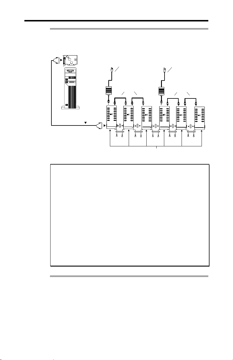
Figure 13: Connection of six ACM/16/16RJ/Flex16 modules
NT960/PCI Host Adapter
P3 P3
DB37 connector
Power supply
Power supply
Power cables
Power cables
Host Computer
Bus cable
Gende r
Changer
Gende r
Changer
Gende r
Changer
Gender
Changer
Gender
Changer
DB37 connector
Metal Straps
&
Screws
Metal Straps
&
Screws
ACM/16, ACM/16RJ or ACM/F lex16
Metal Straps
&
Screws
Metal Straps
&
Screws
Metal Straps
&
Screws
Note:
1. The ACM/Flex16 with RS-232 and/or 20mA Current Loop
interfaces only requires the connection of one external power
supply for every 48 ports connected to a HOST Adapter.
2. The ACM/Flex16 with RS-485 only or a combination of
RS-232 and RS-485 and 20mA Current Loop interfaces
requires the connection of one external power supply for
every 32 ports connected to a HOST Adapter.
3. Please install all the metal straps provided to insure a
proper connection between ACM/16/16RJ/Flex16 modules.
You should install these straps between both the top and the
bottom of the ACM/16/16RJ/Flex16 modules. Failure to do
so will cause an intermittent connection that will disrupt
communications.
Intellicon-NT960/PCI User's Manual, ver. 0.02
Page 46

Intellicon-NT960/PCI User's Manual, ver. 0.02 Intellicon-NT960/PCI User's Manual, ver. 0.02
Page 47

Chapter 3: Software Installation
Introduction ........................................................................................... 3-1
Page 48

Intellicon-NT960/PCI User's Manual, ver. 0.02
Page 49

Chapter 3: Software Installation 3-1
Introduction
Your Intellicon-NT960/PCI subsystem boards may ship with
diskettes that include README files. Please examine these files
for technical tips or release notes concerning installation and
configuration of various device drivers and software utilities. If
you require further information please contact Connect Tech
Customer Support.
Before installing the Intellicon-NT960/PCI software device
driver, verify and note your switch and jumper settings for:
The ACM/16, ACM/16RJ and ACM/Flex16 module(s)
address switch settings.
Technical Tips:
1. Your NT960/PCI subsystem may ship with diskettes that
include README files. Please examine these files for
technical tips or release notes concerning installation and
configuration of various device drivers and software utilities.
2. If you did not receive a driver diskette for your operating
system or you require additional information, please go to
the Download Zone of the Support Center on the Connect Tech
website for product manuals, installation guides and device
driver software.
Intellicon-NT960/PCI User's Manual, ver. 0.02
Page 50

Intellicon-NT960/PCI User's Manual, ver. 0.02 Intellicon-NT960/PCI User's Manual, ver. 0.02
Page 51

Chapter 4: Appendices
Appendix A: Specifications................................................................... 4-1
NT960/PCI Host Adapter............................................................. 4-1
Processor ............................................................................4-1
Memory .............................................................................. 4-1
PCI Bus Interface ...............................................................4-1
Operating Environment ...................................................... 4-1
Power Requirements........................................................... 4-1
Dimensions......................................................................... 4-1
NT960/PCI ACM/16, ACM/16RJ, ACM/Flex16.........................4-1
Asynchronous Communication Module .............................4-1
Operating Environment ...................................................... 4-2
Power Requirements........................................................... 4-2
Dimensions......................................................................... 4-2
NT960/PCI Part Numbers............................................................ 4-3
Certification .................................................................................4-4
Intellicon-NT960/PCI; ACM/16/Flex16/16RJ ...................4-4
FCC .................................................................. 4-4
DOC/IC ............................................................ 4-4
General ...............................................................................4-4
Appendix B: Connector Pinouts............................................................ 4-5
ACM/16 Pinouts ..........................................................................4-5
ACM/Flex16 Pinouts ...................................................................4-6
ACM/Flex16 SLIM Pinouts......................................................... 4-6
ACM/16RJ Pinouts ......................................................................4-9
Appendix C: RS-232 Option ...............................................................4-10
Installation .................................................................................4-11
LED interface indicators............................................................ 4-11
Appendix D: RS-485/422 Option ........................................................ 4-12
Introduction................................................................................ 4-12
Installation .................................................................................4-14
LED interface indicators............................................................ 4-14
Configuration options ................................................................4-15
Line bias feature ............................................................... 4-17
Line load options.............................................................. 4-17
RS-485/422 Cable Wiring.......................................................... 4-20
Appendix E: 20mA Current Loop Option ........................................... 4-22
Installation .................................................................................4-23
LED interface indicators............................................................ 4-23
20mA Current Loop................................................................... 4-24
Current Loop Cable Wiring .......................................................4-25
Page 52

Appendix F: SLIM Insertion/Removal................................................ 4-26
ACM/Flex16 back cover removal.............................................. 4-27
SLIM insertion........................................................................... 4-28
SLIM removal............................................................................ 4-29
Appendix G: Factory Settings ............................................................. 4-30
NT960/PCI Host Adapter........................................................... 4-30
ACM/16, ACM/Flex16, ACM/16RJ Modules ........................... 4-31
ACM/16, ACM/Flex16, ACM/16RJ Address Setting ......4-31
ACM/Flex16: RS-485 SLIM options ...............................4-34
Intellicon-NT960/PCI User's Manual, ver. 0.02
Page 53

Chapter 4: Appendix A - Specifications 4-1
Appendix A: Specifications
NT960/PCI Host Adapter
Processor
Intel i960 JX 32 bit RISC processor, 33MHz
Memory
1MB of dual ported SRAM
PCI Bus Interface
One 3.3V, 5V or Universal PCI slot
Dual-ported RAM interface
Operating Environment
Ambient temperature: 0 - 70 ° C
Relative humidity: 0 - 90% no condensing
Air movement: no requirement
Altitude: 15,000 feet (5000 metres)
Power Requirements
+3.3 vdc: 900 mA typical, 1.2 A maximum
+5 vdc: 200 mA typical
Dimensions
Length: 14.70 cm
Height: 10.60 cm
Width: 1.50 cm
Weight: 0.10 kg
NT960/PCI ACM/16, ACM/16RJ, ACM/Flex16
Asynchronous Communication Module
ACM/16
Four CLCD1400 RISC like quad UARTs with 12 bytes of
FIFO per channel on the chip
EIA RS232-C Interface
Sixteen RS-232 asynchronous ports with male DB-9
connectors
Ports configurable from 50 up to 115 Kbps
Programmable Baud Rate Generator
Intellicon-NT960/PCI User's Manual, ver. 0.02
Page 54

4-2 Chapter 4: Appendix A - Specifications
ACM/Flex16
Four CLCD1400 RISC like quad UARTs with 12 bytes of
FIFO per channel on the chip
EIA RS232-C and/or RS485/422 Interface and/or 20mA
Current Loop
Sixteen RS-232 and/or RS-485/422 and/or 20mA Current
Loop asynchronous ports with male DB-9 connectors
Ports configurable from 50 up to 115 Kbps
Programmable Baud Rate Generator
ACM/16RJ
Four Cirrus Logic CD1400 RISC like quad UARTs with 24
bytes of FIFO per channel on the chip
EIA RS232-C Interface
Sixteen RS-232 asynchronous ports with RJ-45 connectors
Ports configurable from 50 up to 115 Kbps
Programmable Baud Rate Generator
Operating Environment
ACM/16, ACM/Flex16 and ACM/16RJ
Ambient temperature: 0 - 70 ° C
Relative humidity: 0 - 90% no condensing
Air movement: no requirement
Altitude: 15,000 feet (5,000 metres)
Power Requirements
ACM/16, ACM/Flex16 and ACM/16RJ
Power supply provided
Dimensions
ACM/16
Length: 32.812 cm
Width: 11.562 cm
Height: 4.062 cm
ACM/Flex16
Length: 32.812 cm
Width: 14.100 cm
Height: 4.062 cm
ACM/16RJ
Length: 32.85 cm
Width: 11.55 cm
Height: 4.84 cm
Intellicon-NT960/PCI User's Manual, ver. 0.02
Page 55

Chapter 4: Appendix A - Specifications 4-3
NT960/PCI Part Numbers
NP001 Intellicon-NT960/PCI Host Adapter with 1MB of
RAM.
NTACM16V2 Intellicon-NT960/PCI ACM/16 external module
with DB-9 male connectors.
NTACM16V3 Intellicon-NT960/PCI ACM/16RJ external
module with RJ-45 connectors.
NTACMF16 Intellicon-NT960/PCI ACM/Flex16 external
module with DB-9 male connectors.
NT232SLM ACM/Flex16 RS-232 SLIM.
NT485SLM ACM/Flex16 RS-485 SLIM.
NT20MASLM ACM/Flex16 20mA Current Loop SLIM
NTCAB Intellicon-NT960/PCI bus cable, six feet long.
NTUPSLC Intellicon-NT960/PCI ACM/16, ACM/16RJ or
ACM/Flex16 external module power supply, 110
volts, with power line cord. (one power supply for
every three modules)
NTPS220 Intellicon-NT960/PCI ACM/16, ACM/16RJ or
ACM/Flex16 external module power supply, 220
volts, with no power line cord. (one power supply
for every three modules)
NTACMPC Intellicon-NT960/PCI ACM/16, ACM/16RJ or
ACM/Flex16 power cable (only required to
connect power between ACM modules).
CLIP001 Retaining clip for connecting ACM/16 modules,
version 1, together.
CLIP002 Retaining clip for connecting ACM/16, version 2
modules, ACM/16RJ or ACM/Flex16 modules
together.
Intellicon-NT960/PCI User's Manual, ver. 0.02
Page 56

4-4 Chapter 4: Appendix A - Specifications
Certification
Intellicon-NT960/PCI; ACM/16; ACM/Flex16; ACM/16RJ
FCC
This equipment complies with the requirements in Part 15 of FCC
Rules for a Class A computing device. Operation of this
equipment in a residential area may cause unacceptable
interference to radio and TV reception requiring the operator to
take whatever steps are necessary to correct the interference.
DOC/IC
This Class A digital apparatus meets all the requirements of the
Canadian Interference-Causing Equipment Regulations as defined
in ICES-003.
Cet appareil numérique de la classe A respecte toutes les
exigences du Règlement sur le matériel brouiller du Canada.
General
The above agency conformances were met by independent
laboratory testing of Connect Tech Inc. product(s) with shielded
cables, with metal hoods, attached to either the terminating
connectors or cable assemblies supplied with the product(s).
Failure to follow good EMC/EMI compliant cabling practices
may produce more emissions or less immunity than were
obtained in laboratory measurements.
Operation of this equipment in a residential area may cause
unacceptable interference to radio a TV reception, requiring the
user to take whatever steps necessary to correct the interference.
Intellicon-NT960/PCI User's Manual, ver. 0.02
Page 57
Chapter 4: Appendix B - Connector Pinouts 4-5
Appendix B: Connector Pinouts
A cable with 37 pin connectors connects the IntelliconNT960/PCI host adapter to an ACM/16, ACM/Flex16 or
ACM/16RJ external module. ACM/16, ACM/Flex16 and
ACM/16RJ modules also connect to each other via 37 pin
connectors. These connections are a proprietary external bus
interface not a serial interface, and therefore no pinouts are given
for the 37 pin connectors.
ACM/16 Pinouts
The ACM/16 provides male DB-9 connectors for each port. For
the DB-9 pinout information please refer to Table 3.
Table 3: DB-9 pinouts - ACM/16
Pin No.
1 DCD input
2 RxD input
3 TxD output
4 DTR output
5 SG signal gnd.
6 DSR input
7 RTS output
8 CTS input
9 RI input
RS-232
Signal
Male DB-9 Connector
Direction
1
6
5
9
Technical Tip:
Please ensure that you terminate the DCD or CTS signals if your
application does not use them. The common way to do this is to
connect DCD to DTR and/or to connect CTS to RTS. Failure to
do so may result in a loss of a performance on your IntelliconNT960/PCI subsystem.
Intellicon-NT960/PCI User's Manual, ver. 0.02
Page 58

4-6 Chapter 4: Appendix B - Connector Pinouts
r
ACM/Flex16 Pinouts
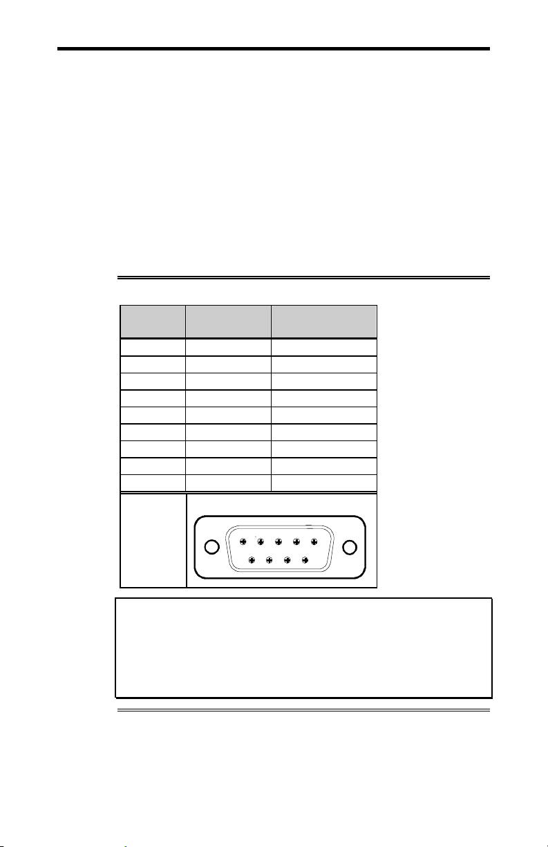
The ACM/Flex16 provides male DB-9 connectors for each port.
For the DB-9 pinout information please refer to Table 4.
Table 4: DB-9 pinouts - ACM/Flex16
Pin No. RS-232
Signal Direction
1 DCD input RxD + input RxD - input
2 RxD input TxD + output TxD + output
3 TxD output TxD - output unused
4 DTR output RxD - input unused
5 SG signal gnd. SG signal gnd. unused
6 DSR input CTS - input unused
7 RTS output RTS - output TxD - output
8 CTS input RTS + output RxD + input
9 RI input CTS + input unused
RS-485
Signal Direction
Male DB-9 Connecto
1
6
Note: ports 3, 4, 7, 8, 11, 12, and 15 do not support the RI signal.
Technical Tip:
Please ensure that you terminate the DCD or CTS signals if your
application does not use them. The common way to do this is to
connect DCD to DTR and/or to connect CTS to RTS. Failure to
do so may result in a loss of a performance on your IntelliconNT960/PCI subsystem.
ACM/Flex16 SLIM Pinouts
You may order the ACM/Flex16 external module with RS-232,
RS-485/422 and/or 20mA Current Loop Serial Line Interface
Modules (SLIM). Please refer to Table 5 for the pinouts for the
SLIM sockets found on the ACM/Flex16 module.
20mA
Signal Direction
5
9
Intellicon-NT960/PCI User's Manual, ver. 0.02
Page 59

Chapter 4: Appendix B - Connector Pinouts 4-7
Table 5: ACM/Flex16 SLIM pinouts
SLIM
Pin No.
1 +12 V
2 RxD 4
3 TxD 4
4 CTS 4
5 RTS 4
6 DSR 4
7 DTR 4
8 DCD 4
9 +5 V
10 DCD 4 RxD B(+) 4 RxD (-) 4
11 DSR 4 CTS A(-) 4
12 RxD 4 TxD B(+) 4 TxD (+) 4
13 RTS 4 RTS A(-) 4 TxD (-) 4
14 TxD 4 TxD A(-) 4
15 CTS 4 RTS B(+) 4 RxD (+) 4
16 DTR 4 RxD A(-) 4
17 RI 4 CTS B(+) 4
18 Ground Signal ground
19 RxD 3
20 TxD 3
21 CTS 3
22 RTS 3
23 DSR 3
24 DTR 3
25 DCD 3
26 Reserved
27 +5 V
28 DCD 3 RxD B(+) 3 RxD (-) 3
29 DSR 3 CTS A(-) 3
30 RxD 3 TxD B(+) 3 TxD (+) 3
31 RTS 3 RTS A(-) 3 TxD (-) 3
32 TxD 3 TxD A(-) 3
33 CTS 3 RTS B(+) 3 RxD (+) 3
34 DTR 3 RxD A(-) 3
35 RI 3 CTS B(+) 3
36 Ground Signal ground
TTL
Signal
RS-232
Signal
RS-485/422
Signal
Current Loop
Signal
Intellicon-NT960/PCI User's Manual, ver. 0.02
Page 60

4-8 Chapter 4: Appendix B - Connector Pinouts
Table 5(continued): ACM/Flex16 SLIM pinouts
SLIM
Pin No.
37 Ground
38 RxD 2
39 TxD 2
40 CTS 2
41 RTS 2
42 DSR 2
43 DTR 2
44 DCD 2
45 RI 2
46 DCD 2 RxD B(+) 2 RxD (-) 2
47 DSR 2 CTS A(-) 2
48 RxD 2 TxD B(+) 2 TxD (+) 2
49 RTS 2 RTS A(-) 2 TxD (-) 2
50 TxD 2 TxD A(-) 2
51 CTS 2 RTS B(+) 2 RxD (+) 2
52 DTR 2 RxD A(-) 2
53 RI 2 CTS B(+) 2
54 Ground Signal ground
55 RxD 1
56 TxD 1
57 CTS 1
58 RTS 1
59 DSR 1
60 DTR 1
61 DCD 1
62 RI 1
63 -12 V
64 DCD 1 RxD B(+) 1 RxD (-) 1
65 DSR 1 CTS A(-) 1
66 RxD 1 TxD B(+) 1 TxD (+) 1
67 RTS 1 RTS A(-) 1 TxD (-) 1
68 TxD 1 TxD A(-) 1
69 CTS 1 RTS B(+) 1 RxD (+) 1
70 DTR 1 RxD A(-) 1
71 RI 1 CTS B(+) 1
72 Ground Signal ground
TTL
Signal
RS-232
Signal
RS-485/422
Signal
Current Loop
Signal
Intellicon-NT960/PCI User's Manual, ver. 0.02
Page 61
Chapter 4: Appendix B - Connector Pinouts 4-9
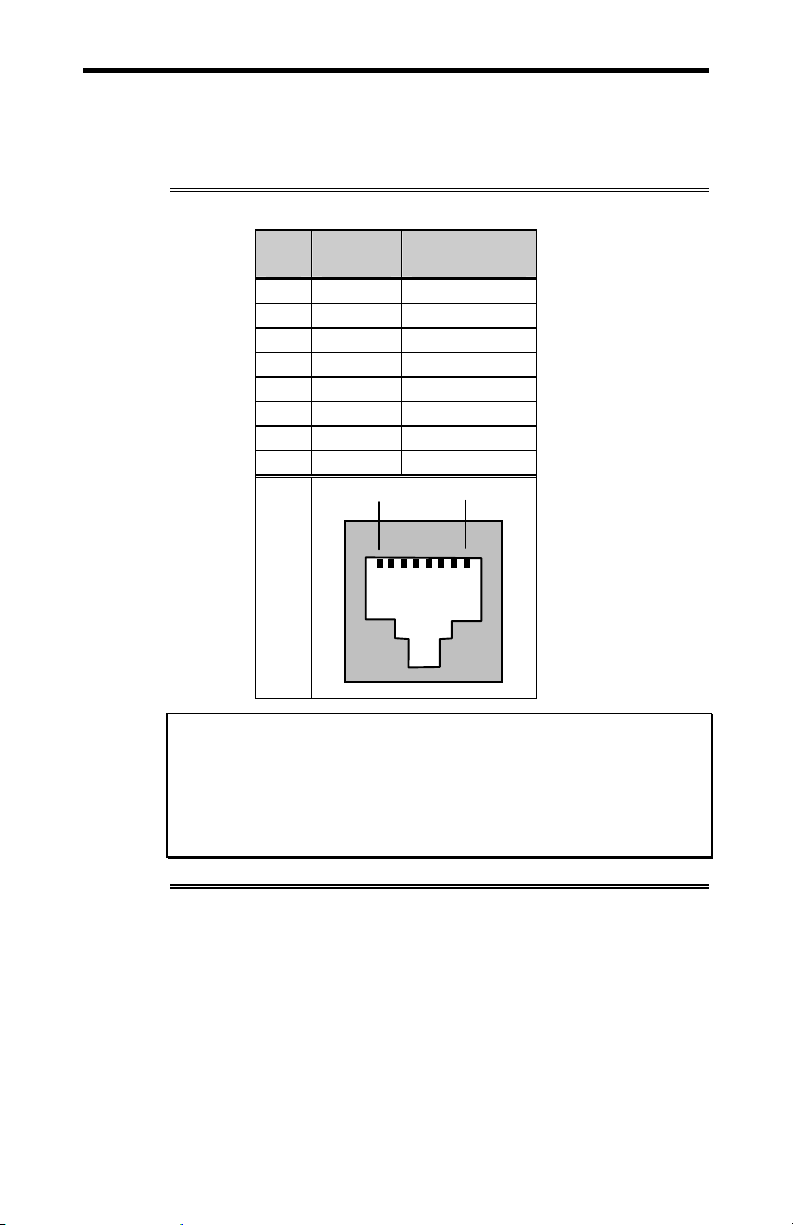
ACM/16RJ Pinouts
The ACM/16RJ provides RJ-45 modular connectors for each
port. For the RJ-45 pinout information please refer to Table 6.
Table 6: RJ-45 pinouts - ACM/16RJ
Pin
RS-232
No.
Signal Direction
1 DCD input
2 RTS output
3 SR
4 TxD output
5 RxD input
6 SR
7 CTS input
8 DTR output
Pin 1 Pin 8
Technical Tip:
Please ensure that you terminate the DCD or CTS signals if your
application does not use them. The common way to do this is to
connect DCD to DTR and/or to connect CTS to RTS. Failure to
do so may result in a loss of a performance on your IntelliconNT960/PCI subsystem.
Intellicon-NT960/PCI User's Manual, ver. 0.02
Page 62

4-10 Chapter 4: Appendix C - RS-232 Option
Appendix C: RS-232 Option
You may order the ACM/Flex16 external module with RS-232
Serial Line Interface Modules (SLIM). The RS-232 SLIM offers
the following features:
Each SLIM controls four ports.
LEDs on the ACM/Flex16 indicate the electrical interface in
use for specific groups of four ports.
SLIMS are field upgradeable, providing you with more
flexibility for your application.
Please refer to Figure 14 for a partial schematic of the RS-232
SLIM.
Figure 14: RS-232 SLIM partial schematic
Connector
RS-232 SLIM partial schematic
DB9
3
4
7
9
8
6
2
1
TxD
DTR
RTS
UART
RI
CTS
22K 22K
Note: The RS-232 Serial Line Interface Module controls four
ports, and therefore the schematic shows only a portion of the
circuit.
Intellicon-NT960/PCI User's Manual, ver. 0.02
22K
22K 22K
DSR
RXD
DCD
-12 V
Page 63

Chapter 4: Appendix C - RS-232 Option 4-11
Installation
The ACM/Flex16 module has four 72 pin SLIM sockets which
accept Serial Line Interface Modules. Each SLIM provides the
RS-232 or RS-485/422 or 20mA Current Loop receivers and
transmitters to condition four serial ports. SLIM 1 socket (SM1)
interfaces ports 1, 2, 3, 4; SLIM 2 socket (SM2) interfaces ports 5,
6, 7, 8; SLIM 3 socket (SM3) interfaces ports 9, 10, 11, 12; and
SLIM 4 socket (SM4) interfaces ports 13, 14, 15, 16. Please refer
to Figure 9 for the location of the SLIM sockets and to Appendix
F: SLIM Insertion/Removal for the proper procedures to
installing and removing SLIMs.
Your ACM/Flex16 and Serial Line Interface Module (SLIM) are
very sensitive to static electricity. Make sure that before you
remove them from the anti-static shipping bag, you wear an antistatic wristband. When you remove them from the anti-static bag,
handle them only by the edges and place them on the anti-static
bag or an anti-static mat.
LED interface indicators
You can install RS-232 and/or RS-485/422 and/or 20mA Current
Loop Serial Line Interface Modules in your ACM/Flex 16. The
ACM/Flex16 has LED indicators on its front panel to show you
the electrical interface in use for a specific group of four ports.
When the LED is red the RS-485/422 interface is in use; when it
is green the RS-232 interface is in use; and when it is amber the
20mA Current Loop interface is in use. Please refer to Figure 10
for the location of these LED interface indicators.
Intellicon-NT960/PCI User's Manual, ver. 0.02
Page 64

4-12 Chapter 4: Appendix D - RS-485/422 Option
Appendix D: RS-485/422 Option
Introduction
You may order the ACM/Flex16 external module with RS485/422 Serial Line Interface Modules (SLIM). The RS-485/422
SLIM offers the following features:
DIP switch selectable line load and bias options.
Each SLIM controls four ports.
LEDs on the ACM/Flex16 indicate the electrical interface in
use for a specific group of four ports.
SLIMs are field upgradeable, providing you with more
flexibility for your application.
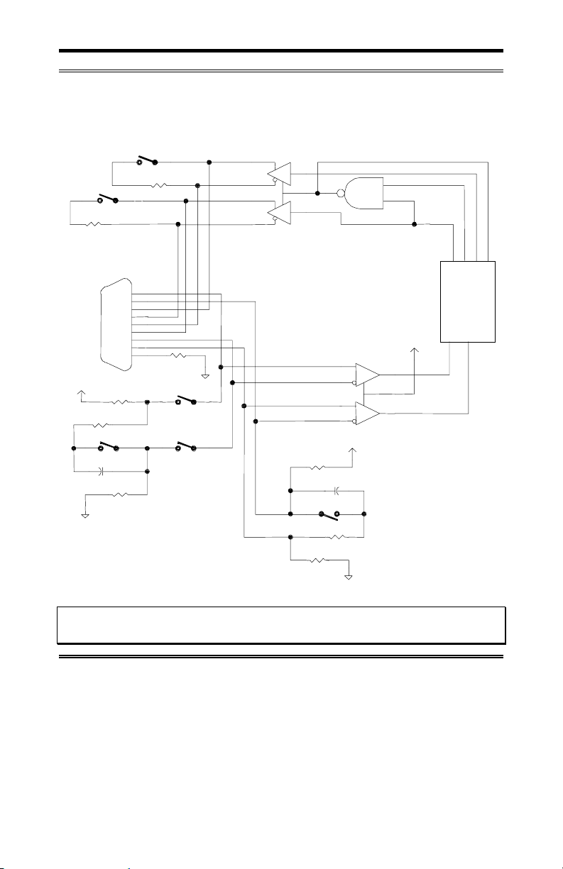
Please refer to Figure 15 for a partial schematic of the RS485/422 SLIM.
Intellicon-NT960/PCI User's Manual, ver. 0.02
Page 65
Chapter 4: Appendix D - RS-485/422 Option 4-13
Figure 15: RS-485/422 SLIM partial schematic
RS-485/422 SLIM partial schematic
TxD load
150R
RTS load
Connector
+5V
150R
50nF
GND
1
2
150R
TX+
TX-
RTS+
RTS-
DB9
1
6
2
7
3
8
4
9
5
1K8
54
1K8
100
GND
3
RxD load
and bias
RX+
RX-
CTS+
CTS-
1K8
1K8
50nF
6
150R
DSR1
TX1
DTR1
RTS1
UART
+5V
RX1
CTS1
+5V
CTS load
and bias
GND
Note: The RS-485/422 Serial Line Interface Module controls four ports, and
therefore the schematic shows only a portion of the circuit.
Intellicon-NT960/PCI User's Manual, ver. 0.02
Page 66

4-14 Chapter 4: Appendix D - RS-485/422 Option
Installation
The ACM/Flex16 module has four 72 pin SLIM sockets which
accept Serial Line Interface Modules. Each SLIM provides the
RS-232 or RS-485/422 or 20mA Current Loop receivers and
transmitters to condition four serial ports. SLIM 1 socket (SM1)
interfaces ports 1, 2, 3, 4; SLIM 2 socket (SM2) interfaces ports
5, 6, 7, 8; SLIM 3 socket (SM3) interfaces ports 9, 10, 11, 12; and
SLIM 4 socket (SM4) interfaces ports 13, 14, 15, 16. Please refer
to Figure 9 for the location of the SLIM sockets and to
Appendix F: SLIM Insertion/Removal for the proper
procedures to installing and removing SLIMs.
Your ACM/Flex16 and Serial Line Interface Module (SLIM) are
very sensitive to static electricity. Make sure that before you
remove them from the anti-static shipping bag, you wear an antistatic wristband. When you remove them from the anti-static bag,
handle them only by the edges and place them on the anti-static
bag or an anti-static mat.
LED interface indicators
You can install RS-232 and/or RS-485/422 and/or 20mA Current
Loop Serial Line Interface Modules in your ACM/Flex 16. The
ACM/Flex16 has LED indicators on its front panel to show you
the electrical interface in use for a specific group of four ports.
When the LED is red the RS-485/422 interface is in use; when it
is green the RS-232 interface is in use; and when it is amber the
20mA Current Loop interface is in use. Please refer to Figure 10
for the location of these LED interface indicators.
Intellicon-NT960/PCI User's Manual, ver. 0.02
Page 67

Chapter 4: Appendix D - RS-485/422 Option 4-15
Configuration options
The RS-485/422 SLIM on the ACM/Flex16 offers a wide range of
features and configuration options. These features and options
include:
Line bias features
Line load options
You select these options and features by four (one for each port),
6 position DIP switches on the SLIM. Please refer to Figure 16
for the locations of these DIP switches on the RS-485/422 SLIM.
Please refer to Table 7 for the port number/switch block
relationship; and to Table 8 for a summary of the line load
options.
WARNING
Do not use a pencil to set the DIP switches as the lead graphite
may short-circuit the switch.
Figure 16: RS-485/422 SLIM - DIP switches
RS-485 SLIM
1995, CO NNECT TECH IN C.RS485 65825 REV.A
S1
S2
S3 S4
Intellicon-NT960/PCI User's Manual, ver. 0.02
Page 68

4-16 Chapter 4: Appendix D - RS-485/422 Option
Table 7: RS-485/422 SLIM; port/switch block relation
Port
number
SLIM
socket
Switch
block
Port
number
1 SM1 S4 9 SM3 S4
2 SM1 S3 10 SM3 S3
3 SM1 S2 11 SM3 S2
4 SM1 S1 12 SM3 S1
5 SM2 S4 13 SM4 S4
6 SM2 S3 14 SM4 S3
7 SM2 S2 15 SM4 S2
8 SM2 S1 16 SM4 S1
Table 8: RS-485/422 SLIM; line load options
Switch
Position
1 TxD load is removed TxD load enabled (150 ohms)
2 RTS load is removed RTS load enabled (150 ohms)
3 & 4 RxD disconnected from
5 RxD load is AC (150
6 CTS load is AC (150
Configuration
(when OFF)
bias and load circuits
Note: These two switches
MUST be used together
ohms in series with 50 nF
and > 50 metres in length)
ohms in series with 50 nF)
Configuration
(when ON)
RxD connected to bias and
load circuits
RxD load is DC (150 ohms
and < 50 metres in length)
CTS load is DC (150 ohms)
Technical Tip: We recommend that you set the switches 3, 4 and
5 on the RS-485/422 SLIM to the ON (up) position for most RS485 configurations.
SLIM
socket
Switch
block
Intellicon-NT960/PCI User's Manual, ver. 0.02
Page 69

Chapter 4: Appendix D - RS-485/422 Option 4-17
Line bias feature
During the operation of a half duplex, or multi-drop RS-485/422
connection, there are situations (time intervals) when there is NO
"generator station" driving the wires that interconnect the various
stations. During these intervals the connection is susceptible to
electrical interference from outside sources. The RS-485/422
SLIM has fixed bias circuits to reduce the sensitivity to electrical
interference when no "generator station" (TxD and RTS) is
driving the cable. These bias circuits force the "receiver stations"
(RxD and CTS) into a known state.
Line load options
RS-485/422 lines normally need some type of load to prevent an
impedance mismatch that causes signal interference. The RS485/422 specification defines line termination loads placed on
either end of a twisted pair cable segment. Please refer to Figure
17 as an example of a typical circuit for a RS-485 application.
Figure 17: Typical RS-485 circuit
Typical RS-485 Circuit
G
Station A
G
Station B
where:
G = generationg station
R = receiving station
Intellicon-NT960/PCI User's Manual, ver. 0.02
R
Station D
R
Station C
Page 70

4-18 Chapter 4: Appendix D - RS-485/422 Option
DIP switches S1, S2, S3, and S4 on the RS-485/422 SLIM allow
you to select a "generator station" load and a "receiver station"
load. The "generator station" is either the TxD or RTS signals.
The "receiver station" is either the RxD or CTS signals.
The RS-485 SLIM also offers you the additional functionality to
disconnect the RxD signal pair COMPLETELY from the load and
bias circuits. This allows you to "multi-drop" the RxD station on a
half duplex communication line. You select this option with
switch positions 3 and 4 on switch blocks S1, S2, S3, and S4.
Please refer to the following examples concerning this option and
their switch settings.
Examples:
1. The following example shows the RxD signal pairs on a
ACM/Flex16 port disconnected from the load and bias
circuits for multi-drop on a half duplex line.
switch blocks
S1, S2, S3, or S4
2. The following example shows the RxD signal pairs on a
ACM/Flex16 port connected to the load and bias circuits.
switch blocks
S1, S2, S3, or S4
Switch positions 1 and 2 on switch blocks S1, S2, S3 and S4
allow the "generator stations" (TxD and RTS) to have either no
load or a DC load of 150 ohms. Please refer to the examples
following for these configuration options and their switch settings.
Intellicon-NT960/PCI User's Manual, ver. 0.02
Page 71

Chapter 4: Appendix D - RS-485/422 Option 4-19
Switch positions 5 and 6 on switch blocks S1, S2, S3, and S4
allow the "receiver stations" (RxD and CTS) to have either a DC
load of 150 ohms or an AC load of 150 ohms in series with a 50
nF capacitor. Please refer to the examples following for these
configuration options and their switch settings.
Examples:
1. The following example shows the switch settings for Station A
as per Figure 17 where TxD and RTS have a load of 150 Ω.
switch blocks
S1, S2, S3, or S4
2. The following example shows the switch settings for Station B
and Station C as per Figure 17.
switch blocks
S1, S2, S3, or S4
3. The following example shows the switch settings for Station
D as per Figure 17 where RxD and CTS have a DC load of
150 Ω..
switch blocks
S1, S2, S3, or S4
4. The following example shows the switch settings for Station
D as per Figure 17 where the circuit is > than 50 metres in
length and RxD and CTS have an AC load of 150 Ω in series
with 50 nF.
switch blocks
S1, S2, S3, or S4
Intellicon-NT960/PCI User's Manual, ver. 0.02
Page 72

4-20 Chapter 4: Appendix D - RS-485/422 Option
RS-485/422 Cable Wiring
You can wire your ACM/Flex16 with the RS-485/422 option in
various ways to communicate with RS-485/422 peripherals. This
section will describe a few examples of RS-485/422 cabling
schemes.
Figures 18, 19 and 20 describe 8 wire, 4 wire and 2 wire cabling
schemes between a port on the ACM/Flex16 to a port on the RS485/422 peripheral.
Figure 18: RS-485/422 wiring diagram(8 wire)
ACM/Flex16
RS-485 peripheral
TxD +
2
TxD -
3
RxD + TxD +
1
RxD - TxD -
4
RTS +
8
CTS +
9
RTS -
7
CTS -
6
SR SR
5
RxD +
RxD -
RTS +
CTS +
RTS -
CTS -
Figure 19: RS-485/422 wiring diagram(4 wire)
ACM/Flex16
2
3
1
4
8
9
7
6
5
TxD +
TxD -
RxD + TxD +
RxD - TxD RTS +
CTS +
RTS -
CTS SR SR
RS-485 peripheral
RxD +
RxD -
RTS +
CTS +
RTS -
CTS -
Intellicon-NT960/PCI User's Manual, ver. 0.02
Page 73
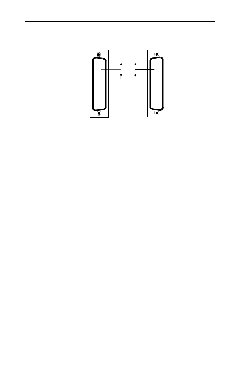
Chapter 4: Appendix D - RS-485/422 Option 4-21
Figure 20: RS-485/422 wiring diagram(2 wire)
ACM/Flex16 RS-485 peripheral
TxD +
2
RxD + TxD +
1
TxD -
3
RxD - TxD -
4
RTS +
8
CTS +
9
RTS -
7
CTS -
6
SR SR
5
RxD +
RxD -
RTS +
CTS +
RTS -
CTS -
Intellicon-NT960/PCI User's Manual, ver. 0.02
Page 74

4-22 Chapter 4: Appendix E - 20mA Current Loop Option
Appendix E: 20mA Current Loop Option
You may order the ACM/Flex16 with 20mA Current Loop Serial
Line Interface Modules. ). The 20mA Current Loop SLIM offers
the following features:
A passive 20mA Current Loop electrical interface.
The 20mA Current Loop receivers and transmitters are
optically isolated.
Each SLIM controls four ports.
LEDs on the ACM/Flex16 indicate the electrical interface in
use for a specific group of four ports.
SLIMs are field upgradeable, providing you with more
flexibility for your application.
Please refer to Figure 21 for a partial schematic of the 20mA
Current Loop SLIM.
Figure 21: 20mA Current Loop partial schematic
20mA Current Loop SLIM: partial schematic
+5V
TxD
8
HPCL
6
4100
5
TxD +
3
TxD -
4
Note: The 20mA Current Loop Serial Line Interface Module
controls four ports, and therefore the schematic shows only a
portion of the circuit.
Intellicon-NT960/PCI User's Manual, ver. 0.02
RxD
+5V
8
RxD +
1
HPCL
7
4200
RxD -
2
5
6
+5V
CTS
DCD
Page 75

Chapter 4: Appendix E - 20mA Current Loop Option 4-23
Installation
The ACM/Flex16 module has four 72 pin SLIM sockets which
accept Serial Line Interface Modules. Each SLIM provides the
RS-232 or RS-485/422 or 20mA Current Loop receivers and
transmitters to condition four serial ports. SLIM 1 socket (SM1)
interfaces ports 1, 2, 3, 4; SLIM 2 socket (SM2) interfaces ports
5, 6, 7, 8; SLIM 3 socket (SM3) interfaces ports 9, 10, 11, 12; and
SLIM 4 socket (SM4) interfaces ports 13, 14, 15, 16. Please refer
to Figure 9 for the location of the SLIM sockets and to
Appendix F: SLIM Insertion/Removal for the proper
procedures to installing and removing SLIMs.
Your ACM/Flex16 and Serial Line Interface Module (SLIM) are
very sensitive to static electricity. Make sure that before you
remove them from the anti-static shipping bag, you wear an antistatic wristband. When you remove them from the anti-static bag,
handle them only by the edges and place them on the anti-static
bag or an anti-static mat.
LED interface indicators
You can install RS-232 and/or RS-485/422 and/or 20mA Current
Loop Serial Line Interface Modules in your ACM/Flex 16. The
ACM/Flex16 has LED indicators on its front panel to show you
the electrical interface in use for a specific group of four ports.
When the LED is red the RS-485/422 interface is in use; when it
is green the RS-232 interface is in use; and when it is amber the
20mA Current Loop interface is in use. Please refer to Figure 10
for the location of these LED interface indicators.
Intellicon-NT960/PCI User's Manual, ver. 0.02
Page 76

4-24 Chapter 4: Appendix E - 20mA Current Loop Option
20mA Current Loop
The 20mA Current Loop module provides optically isolated
20mA passive Current Loop interfaces for four ports. For each
port there is an optically isolated receiver, and an optically
isolated transmitter.
Note:. Please refer to the Hewlett Packard Optoelectronics
Manual/Catalogue for a complete description of HPCL 4100 and
HPCL 4200 specifications.
To implement a passive interface, wire the transmitter and the
receiver, to an external current source.
Please refer to Figure 22 for a 20mA Current Loop cable wiring
configuration between one port of a ACM/Flex16 and another
port of an external device.
WARNING
There is a maximum loop resistance for a Current Loop circuit.
The calculation for Maximum Loop Resistance(R
Note:
Max R
= VOC - (S x VD)
L
0.020
1. S = the number of stations in the loop (TX’s and RX’s).
2. V
= the voltage drop for the HP opto couplers on the SLIM.
D
V
= 2.3 V for the HPCL 4100 and HPCL 4200. When you
D
use other manufacturers’ equipment in the loop the value of
VD may differ.
3. VOC = the open circuit voltage of the current source.
) is:
L
Intellicon-NT960/PCI User's Manual, ver. 0.02
Page 77

Chapter 4: Appendix E - 20mA Current Loop Option 4-25
Current Loop Cable Wiring
You can wire the ACM/Flex16 with the 20mA Current Loop
option in various ways to communicate with 20mA Current Loop
peripherals. This section describes an example of a Current Loop
cabling scheme.
Figure 22 describes a 4 wire cabling scheme between a port on
the ACM/Flex16 and another port on an external device.
Figure 22: Current Loop wiring diagram(4 wire)
External
Current
Source
+
-
TxD +
TxD -
1
RxD -
8
RxD +
ACM/Flex16 Port
DB-9 connector
2
7
-
+
External
Current
Source
RxD -
RxD +
TxD +
TxD -
External Device
Connector
Note:
The example above illustrates a 20mA Current Loop cable wiring
configuration between one port of the ACM/Flex16 and another
port of an external device.
Intellicon-NT960/PCI User's Manual, ver. 0.02
Page 78

4-26 Chapter 4: Appendix F - SLIM Insertion/Removal
Appendix F: SLIM Insertion/Removal
This section outlines procedures for the following:
ACM/Flex16 back cover removal.
SLIM insertion.
SLIM removal.
Your ACM/Flex16 and Serial Line Interface Module (SLIM) are
very sensitive to static electricity. Make sure that before you
remove them from the anti-static shipping bag, you wear an antistatic wristband. When you remove them from the anti-static bag,
handle them only by the edges and place them on the anti-static
bag or an anti-static mat.
Intellicon-NT960/PCI User's Manual, ver. 0.02
Page 79

Chapter 4: Appendix F - SLIM Insertion/Removal 4-27
ACM/Flex16 back cover removal
Figure 23 outlines the correct procedure for removing the back
cover on the ACM/Flex16.
Figure 23: ACM/Flex16 back cover removal
ACM/Flex16
(view from back)
ACM/Flex16 back cover removal
cover
screw
rubber
feet
1. To remove the cover on the back of the ACM/Flex16,
unscrew the four screws on the back cover with the
appropriate screwdriver.
Intellicon-NT960/PCI User's Manual, ver. 0.02
Page 80
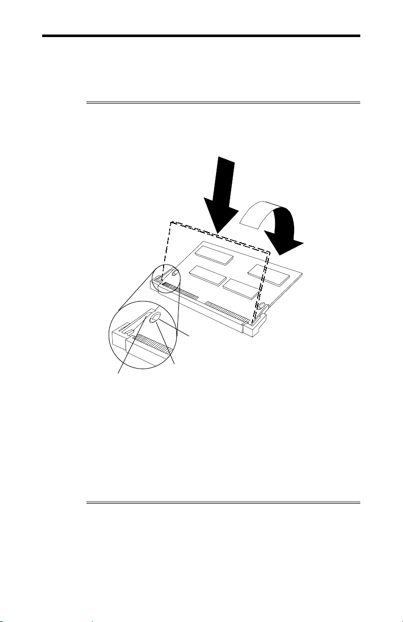
4-28 Chapter 4: Appendix F - SLIM Insertion/Removal
SLIM insertion
Figure 24 outlines the correct procedure for inserting an RS-232,
RS-485/422 and 20mA Current Loop Serial Line Interface
Module (SLIM).
Figure 24: SLIM insertion (ACM/Flex16)
1
2
Hole
Peg
Clip
1. Place the SLIM into the socket almost vertically (about 75degree angle), making sure that it is properly oriented and
fully inserted into the socket.
2. Press downward and sideways on the SLIM until it latches
into the socket. Do NOT force the SLIM, the installation
process requires a small force and should be very smooth and
easy. If you encounter resistance then re-check the orientation
and insertion depth.
Intellicon-NT960/PCI User's Manual, ver. 0.02
Page 81

Chapter 4: Appendix F - SLIM Insertion/Removal 4-29
SLIM removal
Figure 25 outlines the correct procedure for removing an RS-232,
RS-485/422 and 20mA Current Loop Serial Line Interface
Module (SLIM).
Figure 25: SLIM removal(ACM/Flex16)
3
2
1
1. Using both hands, place your thumbs on the clips that hold
the SLIM into the socket, and place your index fingers on the
edge of the SLIM.
2. Push outwards (with your thumbs) on the clips until the
SLIM is released from the clips. Your index fingers can then
raise the SLIM past the clips. The SLIM is then free to be
removed from the ACM/Flex16 board. The force required to
open the clips is small and the SLIM naturally springs
upwards as soon as the clips are open wide enough. If
removal is difficult, then you are probably trying to raise the
SLIM before the clips are open.
Intellicon-NT960/PCI User's Manual, ver. 0.02
Page 82
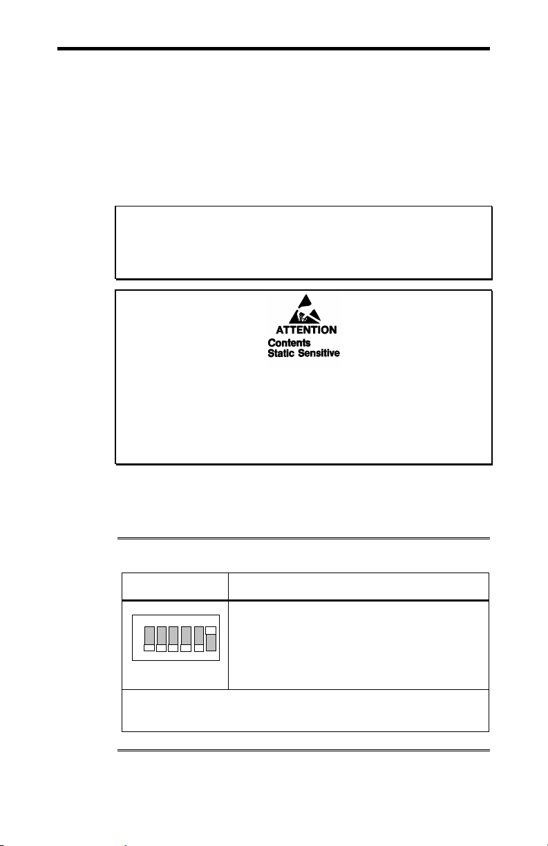
4-30 Chapter 4: Appendix G - Factory Settings
Appendix G: Factory Settings
This section summarizes the factory settings for the following
Intellicon-NT960/PCI hardware components:
Intellicon-NT960/PCI Host Adapter
Intellicon-NT960/PCI ACM/16, ACM/16RJ and
ACM/Flex16
ACM/Flex16 RS-485 SLIM
WARNING
Do not use a pencil to set the DIP switches as the lead graphite
may short-circuit the switch.
Your Intellicon-NT960/PCI adapter, ACM/Flex16 and Serial Line
Interface Module (SLIM) are very sensitive to static electricity.
Make sure that before you remove them from the anti-static
shipping bag, you wear an anti-static wristband. When you
remove them from the anti-static bag, handle them only by the
edges and place them on the anti-static bag or an anti-static mat.
NT960/PCI Host Adapter
The NT960/PCI Host Adapter ships with factory settings for the
following:
Table 9: NT960/PCI SW1 factory settings
Switch Position Configuration
ON
1 2 3 4 5
SW1
Switch 6 on DIP switch block SW1 set
One to 8 ACM modules stacked together,
with only one bus cable between the
6
NT960/PCI Host adapter and the first ACM
module.
on.
Note:
Switches 1 through 5 are set off and must not be changed.
Intellicon-NT960/PCI User's Manual, ver. 0.02
Page 83

Chapter 4: Appendix G - Factory Settings 4-31
ACM/16, ACM/Flex16, ACM/16RJ Modules
The NT960/PCI ACM/16, ACM/16RJ and ACM/Flex16 modules
ship with factory settings for the following:
ACM/16 ACM/16RJ, or ACM/Flex16 address
ACM/Flex16: RS-485 SLIM options
ACM/16, ACM/Flex16, ACM/16RJ Address Setting
The ACM/16, ACM/Flex16 or ACM/16RJ address switch block
or switch assigns a number for each port on that particular
ACM/16, ACM/Flex16 or ACM/16RJ. Connect Tech ships the
ACM/16, ACM/Flex16 and ACM/16RJ with the address switch
block or switch set for address 1. This setting assigns port
numbers 1 through 16 to the serial ports on the ACM/16,
ACM/Flex16 or ACM/16RJ module. Figure 26 shows the
location and factory setting of the ACM/16 and ACM/Flex16
address switch block. Figure 27 shows the location and factory
setting of the ACM/16RJ address switch.
Intellicon-NT960/PCI User's Manual, ver. 0.02
Page 84
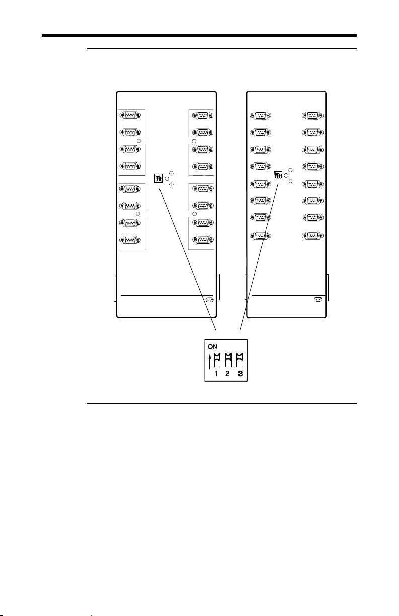
4-32 Chapter 4: Appendix G - Factory Settings
M
A
M
Figure 26: ACM/16, ACM/Flex16 factory settings
ACM/Flex16 ACM/16
1
SLI
2
Type
3
4
5
6
7
89
Activity
Address
SLIM
Type
Intellicon NT960 ACM/Flex16
Connect Tech Inc.
16
15
SLI
Type
14
Powe
13
Traffic
12
SLIM
11
Type
10
1
2
5
6
Address
9
10
13
14
Activity
3
4
7
Power
8
Traffic
11
12
15
16
Intellicon-NT960 ACM/ 16
Connect Tech Inc.
0
ddress
1
Intellicon-NT960/PCI User's Manual, ver. 0.02
Page 85
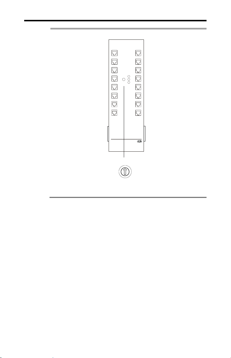
Chapter 4: Appendix G - Factory Settings 4-33
Figure 27: ACM/16RJ factory setting
PWR-IN PWR-OUT
1
2
5
6
9
10 12
13
14 16
Intellicon NT960 ACM/16RJ
Connect Tech Inc
8
7
6
8
7
Address
3
4
7
Power
1
2
3
Activity
4 5 6
8
Traffic
11
15
1
2
3
4
5
Address
Intellicon-NT960/PCI User's Manual, ver. 0.02
Page 86

4-34 Chapter 4: Appendix G - Factory Settings
ACM/Flex16: RS-485 SLIM options
The RS-485 SLIM for the ACM/Flex16 offers a wide range of
configuration options. These options allow you to choose the line
loads(DC or AC) and biasing for each port. DIP switch blocks
S1, S2, S3, and S4 control these options. Connect Tech ships the
RS-485 SLIM with all DIP switches set to the “OFF” position.
Figure 28 shows the location and the default factory settings for
these DIP switches.
Figure 28: ACM/Flex16 RS-485 SLIM settings
RS-485 SLIM
1995, CONNECT TECH IN C.RS485 65825 RE V.A
S1 S2
S3
S4
Intellicon-NT960/PCI User's Manual, ver. 0.02
Page 87

Intellicon-NT960/PCI User's Manual, ver. 0.02
Page 88

Intellicon-NT960/PCI User's Manual, ver. 0.02
 Loading...