

Page 1

Blue Heat/PCI
PCI Serial Communications
User Manual
Connect Tech Inc
42 Arrow Road
Guelph, Ontario
N1K 1S6
Tel: 519-836-1291
Toll: 800-426-8979 (North America only)
Fax: 519-836-4878
Email: sales@connecttech.com
support@connecttech.com
URL: www.connecttech.com
CTIM-00311, Revision 0.11 June 23 2004
Part Number: MAN071
Page 2

Blue Heat/PCI User’s Manual, Connect Tech Inc.
Limited Lifetime Warranty
Connect Tech Inc. provides a Lifetime Warranty for all Connect Tech Inc. products. Should this
product, in Connect Tech Inc.'s opinion, fail to be in good working order during the warranty
period, Connect Tech Inc. will, at its option, repair or replace this product at no charge, provided
that the product has not been subjected to abuse, misuse, accident, disaster or non Connect Tech
Inc. authorized modification or repair.
You may obtain warranty service by delivering this product to an authorized Connect Tech Inc.
business partner or to Connect Tech Inc. along with proof of purchase. Product returned to
Connect Tech Inc. must be pre-authorized by Connect Tech Inc. with an RMA (Return Material
Authorization) number marked on the outside of the package and sent prepaid, insured and
packaged for safe shipment. Connect Tech Inc. will return this product by prepaid ground
shipment service.
The Connect Tech Inc. Lifetime Warranty is defined as the serviceable life of the product. This
is defined as the period during which all components are available. Should the product prove to
be irreparable, Connect Tech Inc. reserves the right to substitute an equivalent product if
available or to retract Life Time Warranty if no replacement is available.
The above warranty is the only warranty authorized by Connect Tech Inc. Under no
circumstances will Connect Tech Inc. be liable in any way for any damages, including any lost
profits, lost savings or other incidental or consequential damages arising out of the use of, or
inability to use, such product.
Copyright Notice
The information contained in this document is subject to change without notice. Connect Tech
Inc. shall not be liable for errors contained herein or for incidental consequential damages in
connection with the furnishing, performance, or use of this material. This document contains
proprietary information that is protected by copyright. All rights are reserved. No part of this
document may be photocopied, reproduced, or translated to another language without the prior
written consent of Connect Tech, Inc.
Copyright 1997 - 2004 by Connect Tech, Inc.
Trademark Acknowledgment
Connect Tech, Inc. acknowledges all trademarks, registered trademarks and/or copyrights
referred to in this document as the property of their respective owners.
Not listing all possible trademarks or copyright acknowledgments does not constitute a lack of
acknowledgment to the rightful owners of the trademarks and copyrights mentioned in this
document.
Revision 0.11 2
Page 3

Blue Heat/PCI User’s Manual, Connect Tech Inc.
Table of Contents
Limited Lifetime Warranty .............................................................................................................................. 2
Copyright Notice .............................................................................................................................................2
Trademark Acknowledgment...........................................................................................................................2
Table of Contents .............................................................................................................................................3
Customer Support Overview............................................................................................................................5
Contact Information ..................................................................................................5
Certification .............................................................................................................................................6
Introduction .............................................................................................................................................7
Features ...................................................................................................................7
Hardware Installation.....................................................................................................................................14
Installing the Blue Heat/PCI Adapter in your System..................................................14
Configuration.........................................................................................................14
Baud Rate Selection................................................................................................15
RS-422/485 Line Interface.......................................................................................15
Full Duplex Mode.................................................................................................... 15
Half Duplex Mode ................................................................................................... 15
Multi-drop Slave Mode............................................................................................15
20mA Current Loop Interface..................................................................................15
Software Installation...................................................................................................................................... 16
Introduction ...........................................................................................................16
Appendix A: Specifications ...........................................................................................................................17
Operating Environment ...........................................................................................17
Power Requirements ...............................................................................................17
PCI Bus Interface....................................................................................................18
Communications.....................................................................................................18
Control Signals.......................................................................................................18
Surge Suppression ..................................................................................................19
Optical Isolation .....................................................................................................19
Dimensions............................................................................................................19
Connectors/Interface ...............................................................................................20
Appendix B: Connectors/Pinouts...................................................................................................................21
Connector Pinouts...................................................................................................21
Connector Box Pinouts............................................................................................28
Appendix C: RS-422/485 Line Interface .......................................................................................................31
Blue Heat/PCI RS-422/485......................................................................................31
Full Duplex Mode.................................................................................................... 31
Half Duplex Mode ................................................................................................... 31
Multi-drop Slave Mode............................................................................................31
Line Bias/Termination .............................................................................................31
Universal Blue Heat/PCI RS-422/485 .......................................................................31
Tri-state Control.......................................................................................................31
Blue Heat/PCI RS-422/485 (6+2 model) ...................................................................32
Tri-state Control.......................................................................................................32
Line Bias/Termination .............................................................................................32
Blue Heat/PCI Opto and Opto RS-422/485................................................................35
Electrical Interface Selection ...................................................................................35
Full Duplex Mode.................................................................................................... 35
Half Duplex Mode ................................................................................................... 36
Multi-drop Slave Mode............................................................................................36
Tri-state Control.......................................................................................................36
Line/Bias Termination ............................................................................................. 37
RS-422/485 Cable Wiring........................................................................................38
Appendix D: 20mA Current Loop Line Interface ..........................................................................................40
Blue Heat/PCI 20mA CL.........................................................................................40
Current Source/Voltage Selection............................................................................ 41
Current Loop Cable Wiring ..................................................................................... 42
Appendix E: Blue Heat/PCI PTM model.......................................................................................................44
Blue Heat/PCI PTM Adapter....................................................................................44
Features .................................................................................................................44
Specifications for the Blue Heat/PCI PTM ................................................................45
3 Revision 0.11
Page 4

Blue Heat/PCI User’s Manual, Connect Tech Inc.
Power Requirements................................................................................................45
Communications......................................................................................................45
Control Signals ........................................................................................................45
Dimensions .............................................................................................................. 45
Connectors/Interface ................................................................................................ 45
Part Numbers ...........................................................................................................45
Certification ...........................................................................................................45
Connectors/Pinouts .................................................................................................46
List of Figures
Figure 1: Blue Heat/PCI Adapters................................................................................................................. 9
Figure 2: Blue Heat/PCI RS-422/485 adapters............................................................................................ 10
Figure 3: Universal Blue Heat/PCI RS-422/485 adapters...........................................................................11
Figure 4: Blue Heat/PCI RS-422/485 adapter (6+2 model) ........................................................................ 11
Figure 5: Blue Heat/PCI RJ-11 adapter ...................................................................................................... 12
Figure 6: Blue Heat/PCI Opto adapters ...................................................................................................... 12
Figure 7: Blue Heat/PCI adapter................................................................................................................. 13
Figure 8: Blue Heat/PCI, 20-port configuration.......................................................................................... 13
Figure 9: Blue Heat/PCI, RS-422/485, 20mA CL and Universal Blue Heat/PCI RS-422/485 I/O Box....... 29
Figure 10: RJ-45 Connector Plug................................................................................................................ 30
Figure 11: Partial schematic: Blue Heat/PCI RS-422/485; Universal Blue Heat/PCI RS-422-485............ 33
Figure 12: Partial schematic: Blue Heat/PCI Opto..................................................................................... 37
Figure 13: RS-422/485 wiring diagram (4 wire).......................................................................................... 38
Figure 14: RS-422/485 wiring diagram (2 wire).......................................................................................... 39
Figure 15: Partial schematic: Blue Heat/PCI 20mA CL.............................................................................. 40
Figure 16: Current Loop wiring diagram (4 wire)....................................................................................... 42
Figure 17: Blue Heat/PCI PTM adapter...................................................................................................... 44
Figure 18: Blue Heat/PCI PTM Monitor Pass Through Mode Connections ............................................... 47
Figure 19: Blue Heat/PCI PTM Intercept Pass Through Mode Connections.............................................. 47
List of Tables
Table 1: DB-9 pinouts for Blue Heat/PCI RS-232, 422/485 models, Universal Blue Heat/PCI RS-422/48522
Table 2: DB-9 pinouts for the Blue Heat/PCI Opto ..................................................................................... 22
Table 3: RJ-45 pinouts for the Blue Heat/PCI Opto .................................................................................... 23
Table 4: Blue Heat/PCI RJ-11 port header (P7/P8) pinouts........................................................................23
Table 5: Blue Heat/PCI RJ-11 pinouts......................................................................................................... 24
Table 6: Blue Heat/PCI 20mA CL pinouts ................................................................................................... 24
Table 7: DB-37 pinouts for Blue Heat/PCI RS-232 and RS-422/485 models............................................... 25
Table 8: DB-78 pinouts for Blue Heat/PCI RS-232, RS-422/485, Universal Blue Heat/PCI RS-422/485... 26
Table 9: DB-9 pinouts for Blue Heat/PCI RS-232, RS-422/485, 20mA CL and Universal Blue Heat/PCI RS-
422/485 I/O Box ........................................................................................................................................... 29
Table 10: RJ-45 pinouts, RJ-45 connector plug........................................................................................... 30
Table 11: DB-9 pinouts – Blue Heat/PCI PTM............................................................................................ 46
Revision 0.11 4
Page 5

Blue Heat/PCI User’s Manual, Connect Tech Inc.
Customer Support Overview
If you experience difficulties after reading the manual and/or using the product, contact the
Connect Tech reseller from which you purchased the product. In most cases the reseller can help
you with product installation and difficulties.
In the event that the reseller is unable to resolve your problem, our highly qualified support staff
can assist you. Our support section is available 24 hours a day, 7 days a week on our website at:
www.connecttech.com/sub/support/support.asp. See the contact information section below for
more information on how to contact us directly. Our technical support is always free.
Contact Information
We offer three ways for you to contact us:
Mail/Courier
You may contact us by letter at:
Connect Tech Inc.
Technical Support
42 Arrow Road
Guelph, Ontario
Canada N1K 1S6
Email/Internet
You may contact us through the Internet. Our email and URL addresses on the Internet are:
sales@connecttech.com
support@connecttech.com
www.connecttech.com
Note:
Please go to the Download Zone or the Knowledge Database in the
Support Center on the Connect Tech website for product
manuals, installation guides, device driver software and
technical tips.
Submit your technical support questions to our customer
support engineers via the Support Center on the Connect Tech
website.
Telephone/Facsimile
Technical Support representatives are ready to answer your call Monday through Friday, from
8:30 a.m. to 5:00 p.m. Eastern Standard Time. Our numbers for calls are:
Telephone: 800-426-8979 (North America only)
Telephone: 519-836-1291 (Live assistance available 8:30 a.m. to 5:00 p.m. EST, Monday to
Friday)
Facsimile: 519-836-4878 (on-line 24 hours)
5 Revision 0.11
Page 6

Blue Heat/PCI User’s Manual, Connect Tech Inc.
Certification
Blue Heat/PCI
Blue Heat/PCI RS-422/485
Blue Heat/PCI RJ-11
Blue Heat/PCI Opto; Opto RS-422/485
Blue Heat/PCI CL
Universal Blue Heat/PCI RS-422/485
Connect Tech Inc. declares that the product(s) covered by the contents of this manual have been
tested and found compliant with the below listed standards as required by the Electromagnetic
Compatibility (EMC) Directive for General Immunity Compliance, EN 50 0082.1:1997
EN 55022 Conducted and Radiated emissions
CISPR 22 Class A
EN 55024 Immunity to Disturbances
EN 61000-4-2 EN 61000-4-4
EN 61000-4-3 EN 61000-4-6
The above satisfy the requirements of:
USA: FCC – CFR47, Part 15, part 2
Canada: ICES-003
Europe: EMC Directive
Japan: VCCI
Australia/New Zealand: AS/NZS
The above agency conformances were met by independent laboratory testing of Connect Tech
Inc. product(s) with shielded cables, with metal hoods, attached to either the terminating
connectors or cable assemblies supplied with the product(s). Failure to follow good EMC/EMI
compliant cabling practices may produce more emissions or less immunity than were obtained in
laboratory measurements.
Operation of this equipment in a residential area may cause unacceptable interference to radio
and TV reception, requiring the user to take whatever steps necessary to correct the interference.
Industry Industrie
Canada Canada
Revision 0.11 6
Page 7

Blue Heat/PCI User’s Manual, Connect Tech Inc.
Introduction
The Blue Heat/PCI family of adapters includes the Blue Heat/PCI RS-232, RS-422/485, RJ-11,
Opto, 20mA CL and Universal Blue Heat/PCI RS-422/485. provide high speed interfaces,
allowing you to connect up to eight serial devices through one expansion slot.
Your Blue Heat/PCI product consists of the following components:
● One Blue Heat/PCI adapter
● One cable harness or external connector box (four and eight port models only)
● One CD containing device drivers and documentation
Blue Heat/PCI RS-422/485, RJ-11, Opto, Opto RS-422/485, 20mA CL and Universal Blue
Heat/PCI RS-422/485 adapters provide high speed interfaces between a host computer’s PCI bus
and multiple external serial devices.
Features
● 2, 4, or 8 asynchronous serial ports
● Multiple interface options:
RS-232 (Blue Heat/PCI and RJ-11 adapters)
RS-232 and/or RS-422/485 (Blue Heat/PCI RS-422/485, Opto, Opto RS-422/485
and Universal Blue Heat/PCI RS-422/485 adapters)
20mA Current Loop interface (Blue Heat/PCI CL adapters)
● The Blue Heat/PCI RS-422/485, Opto, Opto RS-422/485, Universal Blue Heat/PCI
RS-422/485 offer full RS-422/485 support in hardware. The modes are as follows:
Full Duplex Mode
Half Duplex Mode
Multi-drop Slave Mode
● Different models of Blue Heat/PCI, RS-422/485, RJ-11, 20mA CL, Opto, Opto RS-422/485
and Universal Blue Heat/PCI RS-422/485 adapters may reside in a host computer offering
up to 32 ports per system
● 16C654 quad UARTs control two, four or eight ports (Blue Heat/PCI, RJ-11, 20mA CL
models)
● 16C864 quad UARTs control two, four or eight ports (Blue Heat/PCI RS-422/485,
Universal Blue Heat/PCI RS-422/485 models)
● 16C2850 dual UARTs control two, or four ports (Blue Heat/PCI Opto, /PCI Opto
RS-422/485)
● Each port on a Blue Heat/PCI and RJ-11 models offers independent baud rate selection from
21 bps to 1382.4 Kbps, with 5, 6, 7 or 8 data bits and 1, 1.5, 2 stop bits, odd, even, mark and
space parity
● Each port on a Blue Heat/PCI RS-422/485, Opto, Opto RS-422/485 and Universal Blue
Heat/PCI RS-422/485 adapter offers independent baud rate selection from 50 bps to 921.6
Kbps, with 5, 6, 7 or 8 data bits and 1, 1.5, 2 stop bits, odd, even, mark and space parity
● Each port on a Blue Heat/PCI 20mA CL adapter offers independent baud rate selection from
21 bps to 57.6 Kbps, with 5, 6, 7 or 8 data bits and 1, 1.5, 2 stop bits, odd, even, mark and
space parity
● Blue Heat/PCI, Blue Heat/PCI RS-422/485 and Universal Blue Heat/PCI RS-422/485
adapters come with optional Transient Voltage Protection (surge suppression – IEC 1000-4
compatible) on every signal line of every port
● Each port is independently optically isolated to 1K or 3.0kV AC peak to peak (Blue
Heat/PCI Opto models)
● The RS-232 line drivers on the first three (3) ports offer double the drive capability of
standard RS-232 line drivers (Blue Heat/PCI and RJ-11 models)
7 Revision 0.11
Page 8

Blue Heat/PCI User’s Manual, Connect Tech Inc.
● Six RJ-11 connectors provide +12 VDC or +5 VDC output (factory installed) on pin 6 with
a current limit of 300 mA total for +12 VDC and 1A total for +5 VDC. (Blue Heat/PCI
RJ-11 model)
● System requirements are one 32-bit 5V PCI bus compatible slot (Blue Heat/PCI,
RS-422/485, RJ-11, Opto, Opto RS-422/485, 20mA CL, Universal Blue Heat/PCI
RS-422/485 adapters) or a 3.3V PCI slot (Universal Blue Heat/PCI RS-422/485 adapters
only)
● You can use up to thirty two (32) Blue Heat/PCI, RS-422/485, RJ-11, Opto, Opto
RS-422/485, 20mA CL or Universal Blue Heat/PCI RS-422/485 ports per system for larger
I/O requirements
Revision 0.11 8
Page 9
Blue Heat/PCI User’s Manual, Connect Tech Inc.
g
)
g
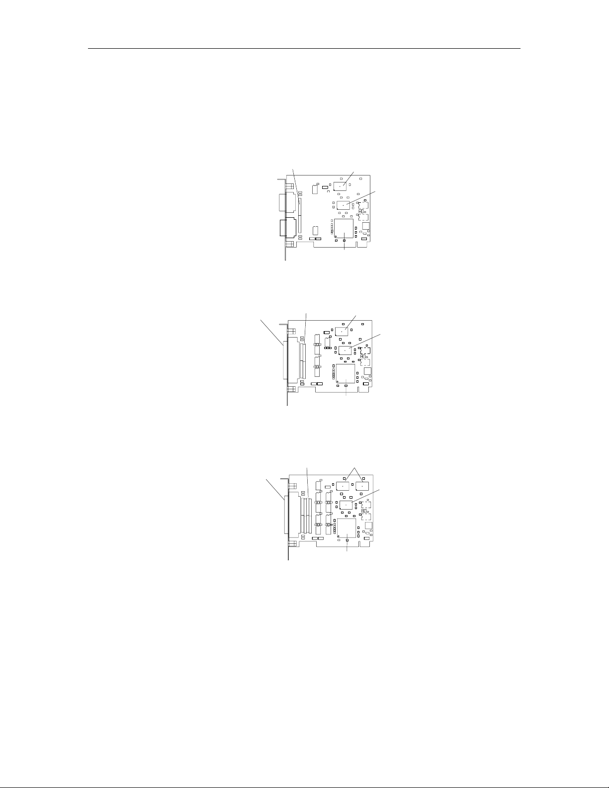
Figures 1 through 7 show the locations of various hardware components found on the Blue
Heat/PCI, RS-422/485, Opto, Opto RS-422/485, RJ-11, 20mA CL and Universal Blue Heat/PCI
RS-422/485 models.
Figure 1: Blue Heat/PCI Adapters
Blue Heat/PCI adapter(2 port model
Surge
Suppression
DB-9
Port 1
DB-9
Port 2
Blue Heat/PCI adapter (4 port model)
16C654 Quad UART
(2 Ports Used)
CPLD
e
PCI Brid
DB-37
Connector
Surge
Suppression
16C654
Quad UART
PCI Brid
e
Blue Heat/PCI adapter (8 port model)
16C654
Quad UARTs
PCI Bridge
DB-78
Connector
Surge
Suppression
CPLD
CPLD
9 Revision 0.11
Page 10
Blue Heat/PCI User’s Manual, Connect Tech Inc.
g
(2 p
g
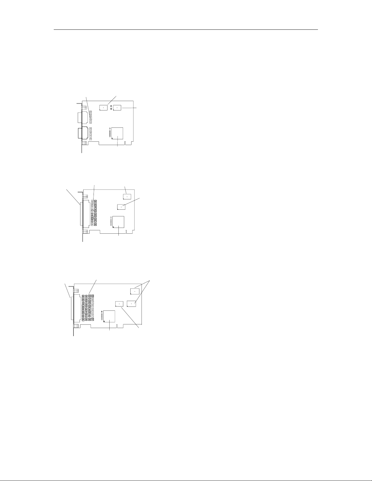
Figure 2: Blue Heat/PCI RS-422/485 adapters
Blue Heat/PCI RS-422/485 adapter
Surge
Suppression
DB-9
Port 2
DB-9
Port 1
Blue Heat/PCI RS-422/485 adapter
DB-37
Connector
ort model)
16C864 Quad UART
(2 Ports Used)
e
PCI Brid
(4 port & 2+2 models)
Surge
Suppression
16C864
Quad UART
CPLD
CPLD
PCI Brid
Blue Heat-8/PCI RS-422/485 adapter
(8 port & 4+4 models)
DB-78
Connector
Surge
Suppression
PCI Bridge
e
16C864
Quad UARTs
CPLD
Revision 0.11 10
Page 11
Blue Heat/PCI User’s Manual, Connect Tech Inc.
g
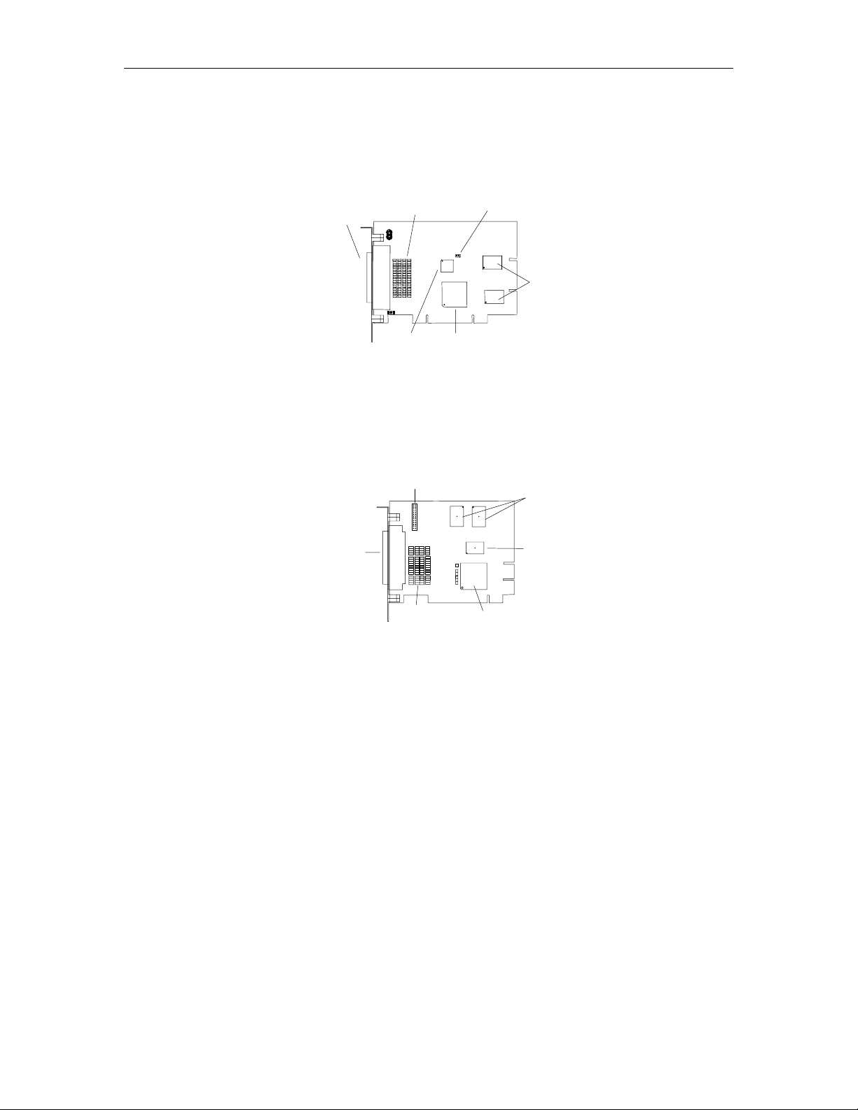
Figure 3: Universal Blue Heat/PCI RS-422/485 adapters
Universal Blue Heat/PCI RS-422/485
(8 port & 4+4 models)
DB-78
Connector
Surge
Suppression
CPLD
PCI Brid
Figure 4: Blue Heat/PCI RS-422/485 adapter (6+2 model)
Blue Heat/PCI RS-422/485 adapter
(6+2 model)
Tri-state control
Line bias termination
J1 through J13
J1 – Tri-state control
16C864
Quad UARTs
e
16C864 Quad
UARTs
DB-78
Connector
Surge
Suppression
PCI Bridge
CPLD
11 Revision 0.11
Page 12
Blue Heat/PCI User’s Manual, Connect Tech Inc.
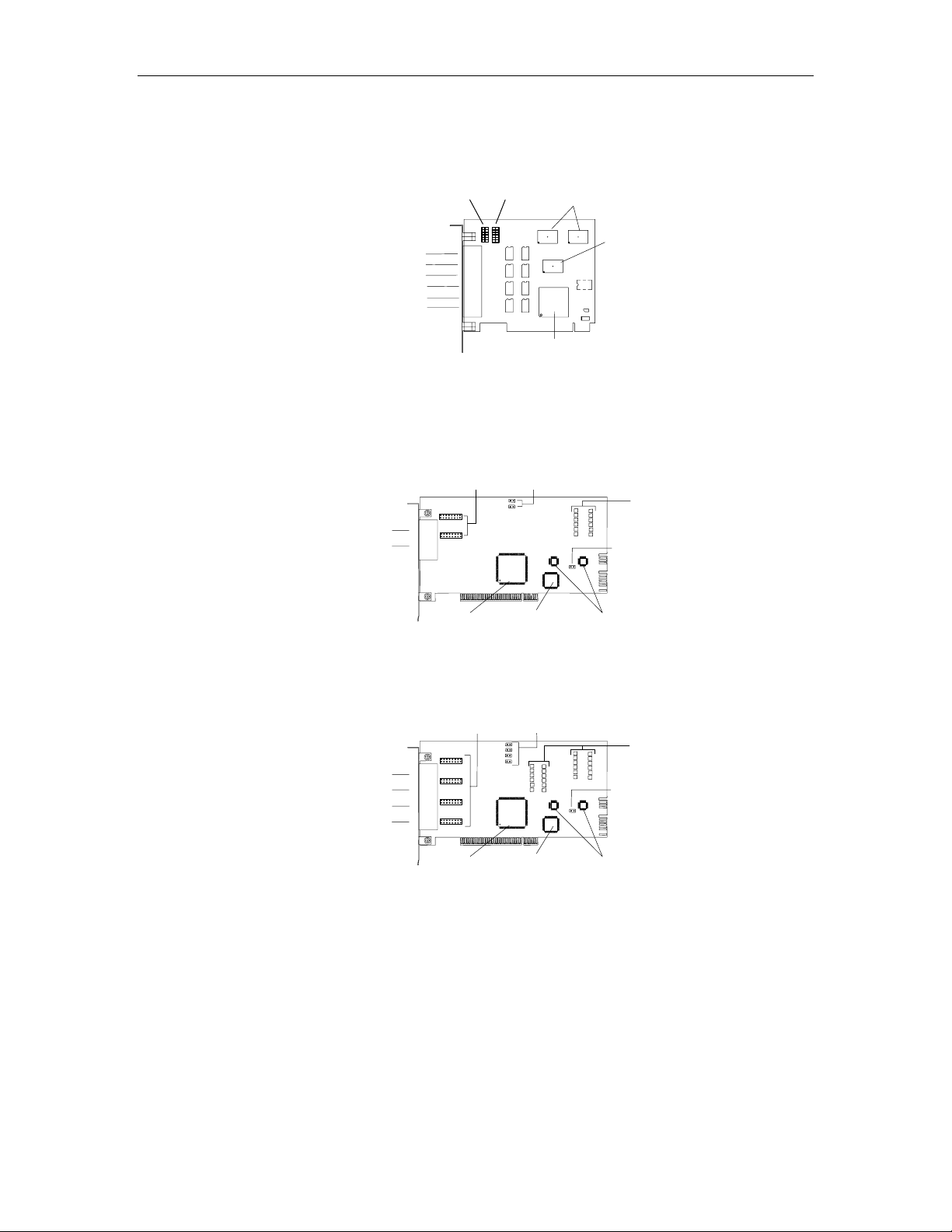
Figure 5: Blue Heat/PCI RJ-11 adapter
Blue Heat/PCI RJ-11 adapter
10 pin headers
Port 7 Port 8
16C654 Quad
UARTs
RJ-11 Connectors
Figure 6: Blue Heat/PCI Opto adapters
Blue Heat/PCI Opto adapter (2 port model)
Blue Heat/PCI Opto RS-422/485 adapter (2 port model)
RJ-45 Connectors
Port 1
Port 2
Blue Heat/PCI Opto RS-422/485 adapter (4 port model)
Jumper blocks – JA, JB, JC, JD
RJ-45 Connectors
Port 1
Port 2
Port 3
Port 4
CPLD
Port 6
Port 5
Port 4
Port 3
Port 2
Port 1
PCI Bridge
Electrical Interface
Termination/Bias
Jumper blocks – JA, JB
PCI Bridge
Jumper blocks – J2, J3
(Blue Heat/PCI Opto)
CPLD
16C2850 Dual
UARTs
Tri-state enable
on powerup
Blue Heat/PCI Opto adapter (4 port model)
Termination/Bias
Electrical Interface
Jumper blocks – J2, J3, J4, J5
(Blue Heat/PCI Opto)
Tri-state enable
on powerup
Optical
Isolators
J1
Optical
Isolators
J1
PCI Bridge
CPLD
16C2850 Dual
UARTs
Revision 0.11 12
Page 13
Blue Heat/PCI User’s Manual, Connect Tech Inc.
Figure 7: Blue Heat/PCI adapter
DB-78
Connector
Blue Heat/PCI CL adapter
Current Source Voltage Select
J1, J2, J3, J4, J5, J6, J7, J8
16C654
Quad UARTs
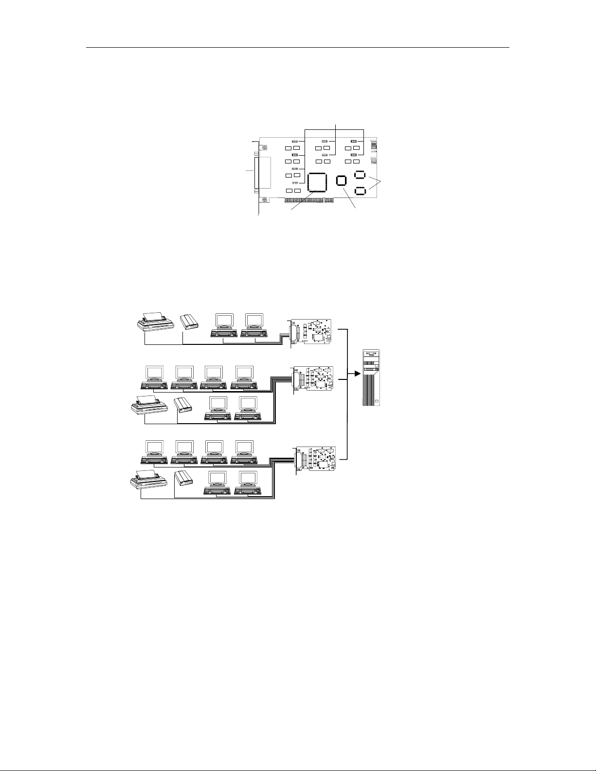
You can combine different Blue Heat/PCI and Universal Blue Heat/PCI RS-422/485 adapters in
a single computer to accommodate both small and large multi-channel applications. Figure 8
below represents a sample configuration for a system requiring 20 ports.
Figure 8: Blue Heat/PCI, 20-port configuration
Printer
Printer
Printer
Modem
Terminals
Modem
Terminals
Modem
Terminals
PCI Bridge
Blue Heat/PCI Opto
Blue Heat/PCI
Blue Heat/PCI RS-422/485
CPLD
Computer
Host
13 Revision 0.11
Page 14

Blue Heat/PCI User’s Manual, Connect Tech Inc.
Hardware Installation
Hardware installation involves configuration of the following Blue Heat/PCI products:
The Blue Heat/PCI; RS-422/485; Opto; Opto RS-422/485; 20mA CL; RJ-11 and Universal Blue
Heat/PCI RS-422/485 adapters
Note: Please see the Software Installation section for
installation of your Blue Heat/PCI or Universal Blue Heat/PCI
Installing the Blue Heat/PCI Adapter in your System
To install your Blue Heat/PCI adapter in your computer follow these steps:
board under certain operating systems.
Your Blue Heat/PCI adapter is very sensitive
to static electricity. Make sure you wear an
anti-static wristband before you remove the
card from the anti-static shipping bag. When
you remove the board from the anti-static
bag, handle it only by the edges and place it
on the anti-static bag or an anti-static mat.
1. Turn the power off to your computer.
2. Open your computer to expose the expansion slots (consult the system documentation for
information on this procedure.)
3. Choose an available 32-bit 5V PCI expansion slot (Blue Heat/PCI; RS-422/485; RJ-11;
Opto; Opto RS-422/485; 20mA CL; Universal Blue Heat/PCI RS-422/485 models) or 3.3V
PCI expansion slot (Universal Blue Heat/PCI RS-422/485 models only).
Note: 3.3V and 5V PCI expansion slots are keyed differently
to prevent incorrect installation of PCI adapters.
4. Remove the screw and the expansion slot cover from the slot you select and save both.
5. Place the Blue Heat/PCI adapter in the expansion slot and push down gently until the card
seats fully in the slot.
Note: Do not force the card into the expansion slot. If you
meet a great deal of resistance remove the board and try
again.
6. Align the mounting bracket and secure the board with the screw that you saved.
7. Close your computer.
Configuration
Peripheral Component Interconnect (PCI) bus architecture offers a feature called Plug and Play
(sometimes referred to as PnP). This feature automatically identifies and configures installed
devices each time the system boots.
In most PCI compliant computers, the system BIOS will automatically detect and configure the
Blue Heat/PCI adapter. However in some cases a system BIOS cannot resolve all of the requests
for resources in the system. This is especially true if you manually assign resources to ISA bus
adapters that the PCI devices need. This often occurs with the assignment of system interrupts,
since this is usually the scarcest resource.
Revision 0.11 14
Page 15

Blue Heat/PCI User’s Manual, Connect Tech Inc.
If this occurs, the driver will signal that a given resource has not been assigned, which requires
the user to assign system resources manually. Remove the assignments for ISA devices with the
BIOS setup and then reboot the computer. After reboot, determine with the BIOS setup utility
what resources have been assigned to the PCI devices and then do manual assignments of free
resources to ISA devices. Reboot your system. If the BIOS cannot find a suitable configuration
please contact Connect Tech Technical Support.
Baud Rate Selection
Blue Heat/PCI adapters offer ideal solutions for applications requiring serial communications up
to 57.6 Kbps (Blue Heat/PCI CL models), 921.6 Kbps (Blue Heat/PCI RS-422/485; Opto; Opto
RS-422/485; Universal Blue Heat/PCI RS-422/485 models) or 1382.4 Kbps (Blue Heat/PCI;
RJ-11 models). Their baud rates are software selectable, so therefore please refer to the
Software Installation section for configuring the baud rates under certain operating systems.
RS-422/485 Line Interface
The Blue Heat/PCI RS-422/485; Opto; Opto RS-422/485 and Universal Blue Heat/PCI
RS-422/485 adapters come with the RS-422/485 electrical line interface. The RS-422/485
electrical interface is a reliable high-speed serial link that offers superior noise immunity and
multi-drop network connectivity. The RS-422/485 electrical interface is also a superset of the
RS-422 electrical interface. These adapters offer full RS-422/485 support in hardware. The
modes are as follows:
Full Duplex Mode
In this mode, TxD & RxD are active all the time. This mode is typically used in point to point
situations much like RS-232. Please refer to Appendix C: RS-422/485 Line Interface.
Half Duplex Mode
In this mode the TxD line driver is enabled only when data is transmitted and RxD is disabled
when data is being transmitted. This mode is typically used in either point to point "2 wire"
connections OR in multi-drop "2 wire" bus connections. Please refer to Appendix C:
RS-422/485 Line Interface.
Multi-drop Slave Mode
In this mode the TxD line driver is enabled only when data is transmitted and RxD is enabled all
the time. This mode is typically used in multi-drop "4 wire" connections. Please refer to
Appendix C: RS-422/485 Line Interface.
20mA Current Loop Interface
The Blue Heat/PCI CL adapter comes with the 20mA Current Loop electrical line interface. The
20mA Current Loop electrical interface provides a reliable high-speed serial link over a long
distance that offers superior noise immunity and multi-drop network connectivity. Please refer
to Appendix D: 20mA Current Loop Interface.
15 Revision 0.11
Page 16

Blue Heat/PCI User’s Manual, Connect Tech Inc.
Software Installation
Introduction
Blue Heat/PCI boards are standard multi-port serial adapters that utilize 16C654, 16C864 or
16C2850 UARTS. In many cases, users have software that will interface directly to the Blue
Heat/PCI boards. Many operating systems come with handlers to control access to multiple
8250 style UARTS. Blue Heat/PCI adapters currently ship with device drivers for the following
operating systems:
● Linux
● QNX 4
● QNX 6
● SCO Unix/Openserver
● SCO UnixWare
● Solaris
● Windows 2000
● Windows 95/98/Me
● Windows CE
● Windows NT
● Windows XP
If you require further information please contact Connect Tech Customer Support.
Technical Tips:
Your Blue Heat/PCI adapter may ship with disks that include
howto.txt or readme.txt files. Please examine these files for
technical tips or release notes concerning installation and
configuration of various device drivers and software utilities.
If you did not receive a driver diskette or CD for your operating
system or you require additional information, please go to the
Download Zone of the Support Center on the Connect Tech
website for product manuals, installation guides, diagnostic
utilities and device driver software.
Revision 0.11 16
Page 17

Blue Heat/PCI User’s Manual, Connect Tech Inc.
Appendix A: Specifications
Operating Environment
Storage temperature: -65° C - 150° C
Operating temperature: 0° C to 70° C
Relative humidity: 5 - 95% non-condensing
Air movement: no requirement
Altitude: 15,000 feet (5000 metres)
Power Requirements
Blue Heat/PCI (2 port model)
+5 VDC +/-5% @ 200 mA (typical
+/-12VDC +/-10% @ 20 mA (typical)
Blue Heat/PCI (4 port model)
+5 VDC +/-5% @ 220 mA (typical)
+/-12VDC +/-10% @ 60 mA (typical)
Blue Heat/PCI (8 port model)
+5 VDC +/-5% @ 320 mA (typical)
+/-12VDC +/-10% @ 120 mA (typical)
Blue Heat/PCI RS-422/485 (8 port model)
+5 VDC ±5% @ 600mA
Blue Heat/PCI RS-422/485 (6+2 model)
+5 VDC ±5% @ 500mA
Blue Heat/PCI RS-422/485 (4+4 model)
+5 VDC ±5% @ 550mA
Blue Heat/PCI RS-422/485 (4 port model)
+5 VDC ±5% @ 400mA
Blue Heat/PCI RS-422/485 (2+2 model)
+5 VDC ± 5% @ 350mA
Blue Heat/PCI RS-422/485 (2 port model)
+5 VDC ±5% @ 300mA
Blue Heat/PCI RJ-11
+5 VDC ±5% @ 400mA (typical)
±12 VDC ±10% @ 144mA (typical)
Blue Heat/PCI Opto; /PCI Opto RS-422/485 (2 port models)
+5 VDC ±5% @ 320mA (typical)
Blue Heat/PCI Opto; /PCI Opto RS-422/485 (4 port models)
+5 VDC ±5% @ 500mA (typical)
Blue Heat/PCI CL
+5 VDC ±5% @ 375mA (typical)
±12 VDC +/-10% 320mA (max.)
Universal Blue Heat/PCI RS-422/485 (4+4 model)
+3 VDC ±5% @ 100mA (typical)
+5 VDC ±5% @ 340mA (typical)
17 Revision 0.11
Page 18

Blue Heat/PCI User’s Manual, Connect Tech Inc.
Power Requirements (continued)
Universal Blue Heat/PCI RS-422/485 (8 port model)
+3 VDC ±5% @ 100mA (typical)
+5 VDC ±5% @ 460mA (typical)
PCI Bus Interface
One 32 bit, 5V PCI slot
One 32 bit 3.3V or 5V PCI slot (Universal Blue Heat/PCI RS-422/485 adapters only)
Communications
Communication controllers:
• Blue Heat/PCI; /PCI RJ-11; 20mA CL models: 16C654 quad UARTs c/w 64 byte TxD/RxD
FIFO buffers
• Blue Heat/PCI RS-422/485 models: 16C864 quad UARTs c/w 128 byte TxD/RxD FIFO
buffers
• Universal Blue Heat/PCI RS-422/485 models: 16C864 quad UARTs c/w 128 byte TxD/RxD
FIFO buffers
• Blue Heat/PCI Opto; Opto RS-422/485 models: 16C2850 dual UARTs c/w 128 byte TxD/RxD
FIFO buffers
Programmable baud rate generator:
• Blue Heat/PCI; RJ-11 models: 21 bps to 1382.4 Kbps on all ports
• Blue Heat/PCI RS-422/485; Opto; Opto RS-422/485; Universal Blue Heat/PCI RS-422/485
models: 50 bps to 921.6 Kbps on all ports
• Blue Heat/PCI CL models: 21 bps to 57.6 Kbps on all ports
Control Signals
Blue Heat/PCI; RS-422/485; Universal Blue Heat/PCI RS-422/485 Models:
• RS-232
• RS-422/485 RTS±; TxD±; CTS±; RxD±
Blue Heat/PCI RJ 11Models:
• RS-232
Ports 1 - 6: RTS; TxD; RxD; DSR; +5 VDC; +12 VDC
Ports 7, 8: DTR; DSR; RTS; CTS; RI; TxD; RxD; DCD
Blue Heat/PCI Opto; Opto RS-422/485 Models:
• RS-232
• RS-422/485 RTS±; TxD±; CTS±; RxD±
Revision 0.11 18
RTS; DTR; TxD; DCD; CTS; RxD; DSR; RI
RTS; TxD; CTS; RxD
Page 19

Blue Heat/PCI User’s Manual, Connect Tech Inc.
Control Signals (continued)
Blue Heat/PCI CL Models:
• 20mA
TxD; RxD
Surge Suppression
Blue Heat Models:
• 500 watts, 8 x 20 µS (EN61000-4-2/3/4 compatible) on every signal of every port.
Blue Heat/PCI RS-422/485; Universal Blue Heat/PCI RS-422/485 Models:
• TransGuard
Transient Voltage Suppression, able to withstand multiple strikes on every
signal of every port.
• Transient Energy dissipation 0.1 joules on every signal of every port
• Transient peak current dissipation 40A on every signal of every port
• EN61000-4-2/3/4 compatible
Optical Isolation
Blue Heat/PCI Opto; Opto RS-422/485 Models:
• 1K or 2.5kV AC peak to peak on every signal of every port.
Dimensions
Blue Heat/PCI (2, 4 & 8 port models)
Length: 12.25 cm Width: 1.50 cm
Height: 10.50 cm Weight: 0.12 kg
Blue Heat/PCI RS-422/485 (8 port & 4+4 models)
Length: 17.30 cm Width: 1.50 cm
Height: 10.50 cm Weight: 0.20 kg
Blue Heat/PCI RS-422/485 (6+2 model)
Length: 13.62 cm Width: 1.50 cm
Height: 10.50 cm Weight: 0.12 kg
Blue Heat/PCI RS-422/485 (4 port & 2+2 models)
Length: 12.00 cm Width: 1.50 cm
Height: 10.50 cm Weight: 0.15 kg
Blue Heat/PCI RS-422/485 (2 port model)
Length: 12.00 cm Width: 1.50 cm
Height: 9.50 cm Weight: 0.13 kg
Blue Heat/PCI RJ-11
Length: 12.25 cm Width: 1.12 cm
Height: 10.60 cm Weight: 0.12 kg
19 Revision 0.11
Page 20

Blue Heat/PCI User’s Manual, Connect Tech Inc.
Dimensions (continued)
Blue Heat/PCI Opto; Opto RS-422/485 (2 & 4 port models)
Length: 19.50 cm Width: 1.50 cm
Height: 9.50 cm Weight: 0.12 kg
Blue Heat/PCI 20mA CL
Length: 18.00 cm Width: 1.50 cm
Height: 10.50 cm Weight: 0.12 kg
Universal Blue Heat/PCI RS-422/485
Length: 10.00 cm Width: 1.50 cm
Height: 10.50 cm Weight: 0.20 kg
Connectors/Interface
● Blue Heat/PCI; RS-422/485; 20mA CL; Universal Blue Heat/PCI RS-422/485; I/O Connector
Box:
9-pin male DB-9
● Blue Heat/PCI RJ-11:
6-pin RJ-11 and optional 9-pin male DB-9
● Blue Heat/PCI Opto; Opto RS-422/485 and RJ-45 Plug:
10-pin RJ-45; optional RJ-45 to male DB-9
Other connection options are available upon request. Contact Connect Tech for details.
Revision 0.11 20
Page 21

Blue Heat/PCI User’s Manual, Connect Tech Inc.
Appendix B: Connectors/Pinouts
Appendix B outlines the pinouts for the following:
● Blue Heat/PCI; RS-422/485; Opto; Opto RS-422/485; RJ-11; 20mA CL and Universal Blue
Heat/PCI RS-422/485 connector pinouts
● Blue Heat/PCI and RS-422/485 and CL and Universal Blue Heat/PCI RS-422/485 external
connector box and RJ-45 Plug pinouts
Connector Pinouts
Tables 1 through 8 show the pinouts for the Blue Heat/PCI and RJ-11, RS-422/485, Opto, Opto
RS-422/485, 20mA CL and Universal Blue Heat/PCI RS-422/485 connectors or cable
connectors.
Note:
The port configuration on the Blue Heat/PCI RS-422/485 (6+2
model) is:
RS-232: Ports 1, 2, 3, 4, 5, 6
RS-422/485: Ports 7, 8
The port configuration on the Blue Heat/PCI RS-422/485 (4+4
model) and Universal Blue Heat/PCI RS-422/485 (4+4 model)
is:
RS-232: Ports 1, 2, 3, 4
RS-422/485: Ports 5, 6, 7, 8
The port configuration on the Blue Heat/PCI RS-422/485 (2+2
model) is:
RS-232: Ports 1, 2
RS-422/485: Ports 3, 4
Technical Tip:
Please ensure that you terminate signals if your application
does not use them. Failure to do so may result in a loss of a
performance on your Blue Heat/PCI adapter.
21 Revision 0.11
Page 22

Blue Heat/PCI User’s Manual, Connect Tech Inc.
Table 1: DB-9 pinouts for Blue Heat/PCI RS-232, 422/485 models, Universal Blue Heat/PCI RS-422/485
Pin No.
RS-232
Signal Direction
RS-422/485
Signal
1 DCD input RxD B(+) input
2 RxD input TxD B(+) output
3 TxD output TxD A(-) output
4 DTR output RxD A(-) input
5 SG signal gnd SR signal ref.
6 DSR input CTS A(-) input
7 RTS output RTS A(-) output
8 CTS input RTS B(+) output
9 RI input CTS B(+) input
Male DB-9 Connector
1
6
Part #(s): CAB04DX
CAB08FXDX
Table 2: DB-9 pinouts for the Blue Heat/PCI Opto
Pin No.
1 N/C no connect RxD (+) input
2 RxD input RxD (-) input
3 TxD output TxD (+) output
4 N/C no connect TxD (-) output
5 SG signal gnd SR signal ref.
6 N/C no connect CTS (-) input
7 RTS output RTS (+) output
8 CTS input CTS (+) input
9 N/C no connect RTS (-) output
RS-232
Signal Direction
Male DB-9 Connector
RS-422/485
Signal
Direction
5
9
Direction
1
6
5
9
Part #:
Note:
CABRJ4509
The RS-232 signals do not apply to the Blue Heat/PCI
Opto RS-422/485 adapter.
Revision 0.11 22
Page 23

Blue Heat/PCI User’s Manual, Connect Tech Inc.
Table 3: RJ-45 pinouts for the Blue Heat/PCI Opto
Pin No.
1 N/C no connect RTS (-) output
2 N/C input RxD (+) input
3 RTS output RTS (+) output
4 SG signal gnd SR signal ref.
5 TxD output TxD (+) output
6 RxD input RxD (-) input
7 Gnd ground Gnd. ground
8 CTS input CTS (+) input
9 N/C no connect TxD (-) output
10 N/C no connect CTS (-) input
Note:
RS-232
Signal Direction
RS-422/485
Signal
RJ-45 connector
1
10
Direction
The RS-232 signals do not apply to the Blue Heat/PCI
Opto RS-422/485 adapter
Table 4: Blue Heat/PCI RJ-11 port header (P7/P8) pinouts
Pin No. RS-232 Direction
1 DCD input
2 DSR input
3 RxD input
4 RTS output
5 TxD output
6 CTS input
7 DTR output
8 RI input
9 SG signal gnd.
10 N/C no connect
1
3
5
7
9
2
4
6
8
10
P7/P8
23 Revision 0.11
Page 24

Blue Heat/PCI User’s Manual, Connect Tech Inc.
Table 5: Blue Heat/PCI RJ-11 pinouts
DB-9
Pin No.
1 DCD input 1 RTS output
2 RxD input 2 RxD input
3 TxD output 3 TxD output
4 DTR output 4 DSR input
5 SG signal ground
6 DSR input
7 RTS output
8 CTS input
9 RI input ** This option is a factory installed option
RS-232
Signal Direction
Male DB-9 Connector
1
6
5
9
RJ-11
Pin No.
5 SG Signal/power
6 +12 VDC**
RS-232
Signal
or +5 VDC**
RJ-11 Connector
1
Direction
ground
output
6
Part #: CAB104K
Technical Tip:
Please ensure that you terminate the CTS signal if your application does
not use them. The common way to do this is to connect CTS to RTS.
Failure to do so may result in loss of a performance on your Blue
Heat/PCI RJ-11 adapter.
Table 6: Blue Heat/PCI 20mA CL pinouts
Pin No. 20mA Signal Direction
1 RxD(-) input
2 TxD(+) output
3 TxD Source output
4 TxD Return output
5 SG signal ground
6 RxD Return input
7 TxD(-) output
8 RxD(+) input
9 RxD Source input
Part No.: CAB08FXDX
Male DB-9 Connector
1
6
5
9
Revision 0.11 24
Page 25

Blue Heat/PCI User’s Manual, Connect Tech Inc.
Table 7: DB-37 pinouts for Blue Heat/PCI RS-232 and RS-422/485 models
Pin
No.
1 1 SG signal gnd SR signal ref
2 1 DTR output RxD A(-) input
3 1 TxD output TxD A(-) output
4 1 RxD input TxD B(+) output
5 1 DCD input RxD B(+) input
6 unused unused
7 3 RI input CTS B(+) input
8 3 CTS input RTS B(+) output
9 3 RTS output RTS A(-) output
10 3 DSR input CTS A(-) input
11 4 RI input CTS B(+) input
12 4 CTS input RTS B(+) output
13 4 RTS output RTS A(-) output
14 4 DSR input CTS A(-) input
15 2 SG signal gnd SR signal ref
16 2 DTR output RxD A(-) input
17 2 TxD output TxD A(-) output
18 2 RxD input TxD B(+) output
19 2 DCD input RxD B(+) input
20 1 RI input CTS B(+) input
21 1 CTS input RTS B(+) output
22 1 RTS output RTS A(-) output
23 1 DSR input CTS A(-) input
24 3 SG signal gnd SR signal ref
25 3 DTR output RxD A(-) input
26 3 TxD output TxD A(-) output
27 3 RxD input TxD B(+) output
28 3 DCD input RxD B(+) input
29 4 SG signal gnd SR signal ref
30 4 DTR output RxD A(-) input
31 4 TxD output TxD A(-) output
32 4 RxD input TxD B(+) output
33 4 DCD input RxD B(+) input
34 2 RI input CTS B(+) input
35 2 CTS input RTS B(+) output
36 2 RTS output RTS A(-) output
37 2 DSR input CTS A(-) input
Part #: CAB04DX
Port
No.
RS-232
Signal Direction
RS-422/485
Signal
Direction
25 Revision 0.11
Page 26

Blue Heat/PCI User’s Manual, Connect Tech Inc.
Table 8: DB-78 pinouts for Blue Heat/PCI RS-232, RS-422/485, Universal Blue Heat/PCI RS-422/485
Pin
Port
No.
RS-232
Signal
No.
1 5 RTS output RTS A(-) output TxD (-) output
2 5 CTS input RTS B(+) output RxD (+) input
3 5 DSR input CTS A(-) input RxD Ret. input
4 5 RI input CTS B(+) input RxD Src. input
5 5 SG signal gnd. SR signal ref. SG signal ref
6 6 RTS output RTS A(-) output TxD (-) output
7 6 CTS input RTS B(+) output RxD (+) input
8 6 DSR input CTS A(-) input RxD Ret. input
9 6 RI input CTS B(+) input RxD Src. input
10 7 RTS output RTS A(-) output TxD (-) output
11 7 CTS input RTS B(+) output RxD (+) input
12 7 DSR input CTS A(-) input RxD Ret. input
13 7 RI input CTS B(+) input RxD Src. input
14 7 SG signal gnd. SR signal ref. SG signal ref
15 8 RTS output RTS A(-) output TxD (-) output
16 8 CTS input RTS B(+) output RxD (+) input
17 8 DSR input CTS A(-) input RxD Ret. input
18 8 RI input CTS B(+) input RxD Src. input
19 NC no connect NC no connect NC no connect
20 NC no connect NC no connect NC no connect
21 5 TxD output TxD A(-) output TxD Src. output
22 5 RxD input TxD B(+) output TxD (+) output
23 5 DTR output RxD A(-) input TxD Ret. output
24 5 DCD input RxD B(+) input RxD (-) input
25 6 SG signal gnd. SR signal ref. SG signal ref
26 6 TxD output TxD A(-) output TxD Src. output
27 6 RxD input TxD B(+) output TxD (+) output
28 6 DTR output RxD A(-) input TxD Ret. output
29 6 DCD input RxD B(+) input RxD (-) input
30 7 TxD output TxD A(-) output TxD Src. output
31 7 RxD input TxD B(+) output TxD (+) output
32 7 DTR output RxD A(-) input TxD Ret. output
33 7 DCD input RxD B(+) input RxD (-) input
34 SG signal gnd. NC no connect NC no connect
35 8 TxD output TxD A(-) output TxD Src. output
36 8 RxD input TxD B(+) output TxD (+) output
37 8 DTR output RxD A(-) input TxD Ret. output
38 8 DCD input RxD B(+) input RxD (-) input
39 8 SG signal gnd. SR signal ref. SG signal ref
…Continued on the next page
Signal
Direction
RS-422/485
Signal
Signal
Direction 20mA
Signal
Direction
Revision 0.11 26
Page 27

Blue Heat/PCI User’s Manual, Connect Tech Inc.
Table 8 (cont.): DB-78 pinouts – Blue Heat/PCI; RS-422/485; 20mA CL; Universal Blue Heat/PCI
Pin
Port
No.
No.
40 1 RTS output RTS A(-) output TxD (-) output
41 1 CTS input RTS B(+) output RxD (+) input
42 1 DSR input CTS A(-) input RxD Ret. input
43 1 RI input CTS B(+) input RxD Src. input
44 1 SG signal gnd. SR signal ref. SG signal ref
45 2 RTS output RTS A(-) output TxD (-) output
46 2 CTS input RTS B(+) output RxD (+) input
47 2 DSR input CTS A(-) input RxD Ret. input
48 2 RI input CTS B(+) input RxD Src. input
49 3 RTS output RTS A(-) output TxD (-) output
50 3 CTS input RTS B(+) output RxD (+) input
51 3 DSR input CTS A(-) input RxD Ret. input
52 3 RI input CTS B(+) input RxD Src. input
53 3 SG signal gnd. SR signal ref. SG signal ref
54 4 RTS output RTS A(-) output TxD (-) output
55 4 CTS input RTS B(+) output RxD (+) input
56 4 DSR input CTS A(-) input RxD Ret. input
57 4 RI input CTS B(+) input RxD Src. input
58 NC no connect NC no connect NC no connect
59 NC no connect NC no connect NC no connect
60 1 TxD output TxD A(-) output TxD Src. output
61 1 RxD input TxD B(+) output TxD (+) output
62 1 DTR output RxD A(-) input TxD Ret. output
63 1 DCD input RxD B(+) input RxD (-) input
64 2 SG signal gnd. SR signal ref. SG signal ref
65 2 TxD output TxD A(-) output TxD Src. output
66 2 RxD input TxD B(+) output TxD (+) output
67 2 DTR output RxD A(-) input TxD Ret. output
68 2 DCD input RxD B(+) input RxD (-) input
69 3 TxD output TxD A(-) output TxD Src. output
70 3 RxD input TxD B(+) output TxD (+) output
71 3 DTR output RxD A(-) input TxD Ret. output
72 3 DCD input RxD B(+) input RxD (-) input
73 4 SG signal gnd. SR signal ref. SG signal ref.
74 4 TxD output TxD A(-) output TxD Src. output
75 4 RxD input TxD B(+) output TxD (+) output
76 4 DTR output RxD A(-) input TxD Ret. output
77 4 DCD input RxD B(+) input RxD (-) input
78 NC no connect NC no connect NC no connect
Cable Part #(s): CAB08FXDX
IOB08DB9
IOB08DB9V1
RS-422/485
RS-232
Signal
Signal
Direction
RS-422/485
Signal
Signal
Direction 20mA
Signal
Direction
27 Revision 0.11
Page 28

Blue Heat/PCI User’s Manual, Connect Tech Inc.
Connector Box Pinouts
You may order the Blue Heat/PCI (8 port model), Blue Heat/PCI RS-422/485 (8 port, 4+4 and
6+2 models) and Blue Heat/PCI CL with an external I/O Box or the RJ-45 Connector Plug
option. The I/O Box option comes with a metal bracket that can be mounted on a wall or other
surface. When you receive the I/O Box, this bracket is clipped on to the back of the connector
box. If you wish to attach the I/O Box to a wall or other surface, just remove the bracket, fasten
it in place, and then re-attach the connector box. If you wish to set the I/O Box on its rubber feet
only, just remove the bracket from the back. See Figure 9 and Figure 10 for the orientation of
the I/O Box and RJ-45 Connector Plug and Table 9 and Table 10 for the DB-9 pinouts on the
connector box and the RJ-45 pinouts on the plug.
Note:
The port configuration on the Blue Heat/PCI RS-422/485 (6+2
model) is:
RS-232: Ports 1, 2, 3, 4, 5, 6
RS-422/485: Ports 7, 8
The port configuration on the Blue Heat/PCI RS-422/485 (4+4
model) and Universal Blue Heat/PCI RS-422/485 (4+4 model)
is:
RS-232: Ports 1, 2, 3, 4
RS-422/485: Ports 5, 6, 7, 8
The port configuration on the Blue Heat/PCI RS-422/485 (2+2
model) is:
RS-232: Ports 1, 2
RS-422/485: Ports 3, 4
Revision 0.11 28
Page 29

Blue Heat/PCI User’s Manual, Connect Tech Inc.
Figure 9: Blue Heat/PCI, RS-422/485, 20mA CL and Universal Blue Heat/PCI RS-422/485 I/O Box
Male DB-9 connectors
External I/O Box
(p/n: IOB0 8DB9 or
IOB08DB9V1)
Mounting bracket
DB-78 connector
Table 9: DB-9 pinouts for Blue Heat/PCI RS-232, RS-422/485, 20mA CL and Universal Blue Heat/PCI
RS-422/485 I/O Box
Pin
RS-232
No.
Signal Direction
1 DCD input RxD B(+) input
RS-422/485
Signal
Direction 20mA
RxD(-)
Direction
input
2 RxD input TxD B(+) output TxD(+) output
3 TxD output TxD A(-) output TxD Source output
4 DTR output RxD A(-) input TxD Return output
5 SG signal gnd. SR signal ref. SG sig. gnd.
6 DSR input CTS A(-) input RxD Return input
7 RTS output RTS A(-) output TxD(-) output
8 CTS Input RTS B(+) output RxD(+) input
9 RI Input CTS B(+) input RxD Source input
Male DB-9 Connector
1
6
5
9
29 Revision 0.11
Page 30

Blue Heat/PCI User’s Manual, Connect Tech Inc.
Figure 10: RJ-45 Connector Plug
1 2 3 4
8 7 5 6
Table 10: RJ-45 pinouts, RJ-45 connector plug
Pin
RS-232
No.
Signal Direction
1 RI input CTS (+) input
2 DSR input CTS (-) input RxD Return input
3 RTS output RTS (-) output TxD (-) output
4 SG signal gnd. FG frame gnd. FG frame gnd.
5 TxD output TxD (-) output TxD Source output
6 RxD input TxD (+) output TxD (+) output
7 Gnd ground Gnd ground Sig. Gnd. signal gnd.
8 CTS input RTS (+) output RxD(+) input
9 DTR output RxD (-) input TxD Return output
10 DCD input RxD (+) input RxD (-) input
RS-422/485
Signal
RJ-45 Connector
Direction 20mA
RxD
Source
Direction
input
1
10
Revision 0.11 30
Page 31

Blue Heat/PCI User’s Manual, Connect Tech Inc.
Appendix C: RS-422/485 Line Interface
For information on how to configure your RS-422/485 interface, find your specific Blue
Heat/PCI model below:
Blue Heat/PCI RS-422/485
You can order the Blue Heat/PCI RS-422/485 adapter with all ports RS-422/485 or a
combination of RS-422/485 and RS-232. The RS-422/485 electrical interface is a reliable highspeed serial link that offers superior noise immunity and multi-drop network connectivity. The
RS-422/485 electrical interface is also a superset of the RS-422 electrical interface. The Blue
Heat/PCI RS-422/485 offers full RS-422/485 support in hardware. The modes are as follows:
Full Duplex Mode
In this mode, TxD & RxD are active all the time. This mode is typically used in point to point
situations much like RS-232.
Half Duplex Mode
In this mode the TxD line driver is enabled only when data is transmitted and RxD is disabled
when data is being transmitted. This mode is typically used in either point to point "2 wire"
connections OR in multi-drop "2 wire" bus connections.
Multi-drop Slave Mode
In this mode the TxD line driver is enabled only when data is transmitted and RxD is enabled all
the time. This mode is typically used in multi-drop "4 wire" connections.
Line Bias/Termination
On the Blue Heat/PCI RS-422/485 the RS-422/485 receivers are biased high through fixed
resistors. Please refer to Figure 11 for a partial schematic.
Universal Blue Heat/PCI RS-422/485
Universal Blue Heat/PCI RS-422/485 adapters offer full RS-422/485 support in hardware like
the other Blue Heat/PCI RS-422/485 models. The modes include full duplex, half duplex, and
multi-drop slave. Universal Blue Heat/PCI RS-422/485 adapters offer the following additional
functionality:
Tri-state Control
Universal Blue Heat/PCI RS-422/485 adapters allow you to tri-state the line drivers on power
up. To tri-state the drivers on power up please ensure there is no jumper installed across the pins
on jumper block JI. Refer to Figure 3 for the location of J1.
Line Bias/Termination
On the Universal Blue Heat/PCI RS-422/485 the RS-422/485 receivers are biased high through
fixed resistors. Please refer to Figure 11 for a partial schematic.
31 Revision 0.11
Page 32

Blue Heat/PCI User’s Manual, Connect Tech Inc.
Blue Heat/PCI RS-422/485 (6+2 model)
The Blue Heat/PCI RS-422/485 (6+2 model) offers full RS-422/485 support in hardware like the
other Blue Heat/PCI RS-422/485 models. The modes include full duplex, half duplex, and multidrop slave. The Blue Heat/PCI RS-422/485 (6+2 model) offers the following additional
functionality.
Tri-state Control
The Blue Heat/PCI RS-422/485 6+2 model allows you to tri-state the line drivers on power up.
To tri-state the drivers on power up please make certain there is no jumper installed across the
pins on jumper block JI. Please refer to Figure 4 for the location of J1.
Line Bias/Termination
You can use jumpers J2, J3, J4, J5, J6, J7, J8, J9, J10, J11, J12, and J13 to terminate and bias
TxD ±, RxD ±, RTS ±, and CTS ± on the RS-422/485 ports 7 and 8. Please refer to Figure 11 for
a partial schematic of the RS-422/485 circuit for the Blue Heat/PCI RS-422/485 (6+2 model)
and Figure 4 for the location of J2, J3, J4, J5, J6, J7, J8, J9, J10, J11, J12, and J13.
Revision 0.11 32
Page 33

Blue Heat/PCI User’s Manual, Connect Tech Inc.
Figure 11: Partial schematic: Blue Heat/PCI RS-422/485; Universal Blue Heat/PCI RS-422-485
16C864
UART
Blue Heat/PCI RS-422/485
Universal Blue Heat/PCI RS-422/485
RS-422/485 Line Bias/Termination
TxD
+5 V
1.8K Ω
RxD
RTS
CTS
150 Ω
1.8K Ω
1.8K Ω
150 Ω
1.8K Ω
+5 V
Note:
1. Line bias and termination is
fixed and permanent.
2. RxD is biased inactive (off,
idle)
3. CTS is biased active (on)
TxD +
TxD -
RxD +
RxD -
RTS +
RTS -
CTS +
CTS -
16C864
UART
Blue Heat/PCI RS-422/485 (6+2 model)
RS-422/485 Line Bias/Termination
TxD
RxD
RTS
CTS
150 Ω
J4, J10
J5, J11
150 Ω
J4, J10
J5, J11
Note:
1. Line bias and termination is
jumper selectable for the Blue
Heat/PCI RS-422/485 (6+2
model).
J2, J8
J3, J9
1.8K Ω
150 Ω
1.8K Ω
1.8K Ω
150 Ω
1.8K Ω
+5 V
+5 V
TxD +
TxD -
RxD +
RxD -
RTS +
RTS -
CTS +
CTS -
4. For custom line bias and
termination requirements
please contact a Connect Tech
Sales Representative
33 Revision 0.11
Page 34

Blue Heat/PCI User’s Manual, Connect Tech Inc.
Example 1 Example 2
The following example shows the
settings on J1 to tri-state the line
drivers upon power up of the Blue
Heat/PCI RS-422/485 adapter (6+2
model). It also shows the settings
on J2 through J13 where the
RS-422/485 port 7 is set for
termination on TxD, RTS and
bias/termination on CTS ±, and
RxD ±; the RS-422/485 port 8 is set
for no bias/termination
Legend
J1
J1 = Tri- state co ntrol
J2 = TxD termination port 7
J2
J3 = RTS termination port 7
J3
J4 = RxD + bias/termination
J4
J5 = RxD - bias/termination
J5
J6 = CTS + bias/termination
J6
J7 = CTS - bias/termination
J7
J8 = TxD termination port 8
J8
J9 = RTS termination port 8
J10 = RxD + bias/termination
J9
J10
J11 = RxD - bias/termination
J11
J12 = CTS + bias/termination
J12
J13 = CTS - bias/termination
J13
port 7
port 7
port 7
port 7
port 8
port 8
port 8
port 8
The following example shows the
settings on J1 to enable the
RS-422/485 transmitters upon
power up of the Blue Heat/PCI
RS-422/485 adapter (6+2 model).
It also shows the settings on J2
through J13 where the RS-422/485
ports 7and 8 are set for no
termination on TxD, RTS and
bias/termination on CTS ±, and
RxD ±
J1
J2
J3
J4
J5
J6
J7
J8
J9
J10
J11
J12
J13
Note:
If you wish to bias/terminate CTS ± on a specific port, you must
jumper both CTS ± positions on the appropriate jumper block.
If you wish to bias/terminate RxD ± on a specific port, you must
jumper both RxD ± positions on the appropriate jumper block.
Legend
J1 = Tri- state co ntrol
J2 = TxD termination port 7
J3 = RTS termination port 7
J4 = RxD + bias/termination
port 7
J5 = RxD - bias/termination
port 7
J6 = CTS + bias/termination
port 7
J7 = CTS - bias/termination
port 7
J8 = TxD termination port 8
J9 = RTS termination port 8
J10 = RxD + bias/termination
port 8
J11 = RxD - bias/termination
port 8
J12 = CTS + bias/termination
port 8
J13 = CTS - bias/termination
port 8
Revision 0.11 34
Page 35

Blue Heat/PCI User’s Manual, Connect Tech Inc.
Blue Heat/PCI Opto and Opto RS-422/485
The Blue Heat/PCI Opto ships with all ports jumper selectable for RS-232 or RS-422/485. The
Blue Heat/PCI Opto RS-422/485 ships with all ports RS-422/485 only. Both the Blue Heat/PCI
Opto and the Blue Heat/PCI Opto RS-422/485 offer full RS-422/485 support in hardware with
three modes: Full Duplex, Half Duplex, and Multi-drop Slave. You enable these modes via
software. See the
different modes
Electrical Interface Selection
The Blue Heat/PCI Opto adapter provides jumper selectable RS-232 and RS-422/485 electrical
interfaces on each port.
Note:
Blue Heat/PCI Opto RS-422/485 adapters provide only an
RS-422/485 electrical interface on each port. Jumper blocks
J2, J3, J4 and J5 are not present, so therefore please
disregard the following interface selection examples for Blue
Heat/PCI Opto RS-422/485 adapters
Jumper blocks J2, J3, J4 and J5 set the electrical interfaces for the individual ports, with J2 for
Port 1, J3 for Port 2, J4 for Port 3, and J5 for Port 4. Jumpers installed on J2, J3, J4 and J5
enable the RS-232 interface for that port, while jumpers not installed enable the RS-422/485
interface for that port. Figure 6 depicts the locations of jumper blocks J2, J3, J4 and J5.
Example 1:
This example shows the
settings on J2 and J3 jumper
blocks so that port 1 is set for
RS-422/485 and port 2 is set
for RS-232.
Technical Note:
You can set up the RS-232 serial ports to run at up to 230.4
Kbps, but you must use good quality cables to maintain high
baud rates over longer distances.
readme files for each operating system concerning details on how to enable the
Example 2:
This example shows the
settings on J2, J3, J4 and J5
jumper blocks so that ports 1,
2 are set for RS-232 and
ports 3, 4 are set for
RS-422/485.
J2
COM1
J3
COM2
J2
COM1
J3
COM2
J4
COM3
J5
COM4
Full Duplex Mode
In this mode, TxD & RxD are active all the time. This mode is typically used in point to point
situations much like RS-232.
35 Revision 0.11
Page 36

Blue Heat/PCI User’s Manual, Connect Tech Inc.
Half Duplex Mode
In this mode the TxD line driver is enabled only when data is transmitted and RxD is disabled
when data is being transmitted. This mode is typically used in either point to point "2 wire"
connections OR in multi-drop "2 wire" bus connections. To enable this mode for a port you
must jumper positions 7 and 8 on the appropriate jumper blocks JA, JB, JC, JD. These jumpers
short TxD – to RxD – and TxD + to RxD +. Figure 6 depicts the locations of jumper blocks JA,
JB, JC and JD.
Example
The following example shows the settings on JA, JB, JC and JD
where the RS-422/485 port 1 is set half duplex, the RS-422/485
port 2 is set for half duplex; RS-422/485 port 3 is set for full
duplex or multi-drop slave, and the RS-422/485 port 4 is set for
full duplex or multi-drop slave.
JD JA
JD1
JD2
JD3
JD4
JD5
JD6
JD7
JD8
COM4
JC1
JC2
JC3
JC4
JC5
JC6
JC7
JC8
COM3
JBJC
COM2
Technical Notes:
If you wish to set a specific port for half duplex, you must
jumper both positions 7 and 8 on the appropriate jumper block.
For RS-232 ports do not jumper any positions on the
appropriate JA, JB, JC and JD jumper block.
JB1
JB2
JB3
JB4
JB5
JB6
JB7
JB8
COM1
JA1
JA2
JA3
JA4
JA5
JA6
JA7
JA8
RTS ± TERM
TXD ± TERM
CTS ± BIAS
CTS ± BIAS
RXD ± BIAS
RXD ± BIAS
Insert for 1/2 D
Insert f or 1/2 D
Multi-drop Slave Mode
In this mode the TxD line driver is enabled only when data is transmitted and RxD is enabled all
the time. This mode is typically used in multi-drop "4 wire" connections.
Tri-state Control
The Blue Heat/PCI Opto adapters allow you to tri-state the line drivers on power up. To tri-state
the drivers on power up please make certain there is no jumper installed across the pins on
jumper block JI. Please refer to Figure 6 for the location of J1.
Example
The following example shows the settings on J1 to tri-state the
transceivers upon power up of the Blue Heat/PCI Opto
adapter.
J1
RS485 TX Power up
ON = ENABLED
OFF = DISABLED
1.
Revision 0.11 36
Page 37

Blue Heat/PCI User’s Manual, Connect Tech Inc.
Line/Bias Termination
You can use jumper blocks JA, JB, JC and JD to terminate and bias TxD ±, RxD ±, RTS ±, and
CTS ± on the individual RS-422/485 ports through jumper selectable 150 Ω fixed resistors.
Please refer to Figure 12 for a partial schematic of the RS-422/485 circuit for the Blue Heat/PCI
Opto and Figure 6 for the locations of JA, JB, JC, and JD.
Figure 12: Partial schematic: Blue Heat/PCI Opto
Blue Heat/PCI Opto
RS-422/485 Line Bias/Termination
TxD +
TxD -
+5 V
RxD +
RxD -
RTS +
RTS -
CTS +
CTS -
+5 V
16C2850
UART
Optical
Isolator
Optical
Isolator
Optical
Isolator
Optical
Isolator
TxD
RxD
RTS
CTS
150 Ω
JA5, JB5, JC5, JD5
JA6, JB6, JC6, JD6
150 Ω
JA4, JB4, JC4, JD4
JA3, JB3, JC3, JD3
JA2, JB2, JC2, JD2
1.8K Ω
150 Ω
1.8K Ω
JA1, JB1, JC1, JD1
1.8K Ω
150 Ω
1.8K Ω
Note: Line bias/termination is jumper selectable
Example
The following example shows the settings on JA, JB, JC and JD
where the RS-422/485 port 1 is set for bias/termination on CTS
±, and RxD ±; the RS-422/485 port 2 is set for bias/termination
on RTS ±, TxD ±, CTS ±, and RxD ±; RS-422/485 port 3 is not
terminated, and the RS-422/485 port 4 is not terminated
JD JA
JD1
JD2
JD3
JD4
JD5
JD6
JD7
JD8
COM4
1.
JC1
JC2
JC3
JC4
JC5
JC6
JC7
JC8
COM3
Technical Notes:
If you wish to bias/terminate CTS ± on a specific port, you must
jumper both CTS ± positions on the appropriate jumper block.
If you wish to bias/terminate RxD ± on a specific port, you must
jumper both RxD ± positions on the appropriate jumper block.
For RS-232 ports do not jumper any positions on the
appropriate JA, JB, JC and JD jumper block.
JBJC
COM2
JB1
JB2
JB3
JB4
JB5
JB6
JB7
JB8
COM1
JA1
JA2
JA3
JA4
JA5
JA6
JA7
JA8
RTS ± TERM
TXD ± TERM
CTS ± BIAS
CTS ± BIAS
RXD ± BIAS
RXD ± BIAS
37 Revision 0.11
Page 38

Blue Heat/PCI User’s Manual, Connect Tech Inc.
r
RS-422/485 Cable Wiring
You can wire Blue Heat/PCI RS-422/485, Opto RS-422/485 and Universal Blue Heat/PCI
RS-422/485 adapters in various ways to communicate with RS-422/485 peripherals. This
section describes a few examples of RS-422/485 cabling schemes.
Figure 13 below describes a 4 wire cabling scheme between a port on the Blue Heat/PCI
RS-422/485, Opto, Opto RS-422/485 or Universal Blue Heat/PCI RS-422/485 adapter to a port
on the RS-422/485 peripheral.
Figure 13: RS-422/485 wiring diagram (4 wire)
Blue Heat/PCI RS- 422/485 adapte
Universal Blu e Heat/PCI RS-422/485 ad apter
RS-422/485 peripheral
TxD +
2
TxD -
3
RxD + TxD +
1
RxD -
4
RTS +
8
CTS +
9
RTS -
7
CTS -
6
SR
5
Blue Heat/PCI Opto ad apter
Blue Heat/PCI O pto RS-422/485 adapter RS-422/485 peripher al
TxD +
3
TxD -
4
RxD + TxD +
1
RxD -
2
RTS +
7
CTS +
8
RTS -
9
CTS -
6
SR
5
RxD +
RxD -
TxD -
RTS +
CTS +
RTS -
CTS -
SR
RxD +
RxD -
TxD -
RTS +
CTS +
RTS -
CTS -
SR
Technical Tip:
The RS-422/485 electrical interface consists of a differential
signaling scheme. You should always connect the signals with
twisted pairs.
Revision 0.11 38
Page 39

Blue Heat/PCI User’s Manual, Connect Tech Inc.
Figure 14 below describes a 2 wire cabling scheme between a port on the Blue Heat/PCI
RS-422/485, Opto, Opto RS-422/485 or Universal Blue Heat/PCI RS-422/485 adapter to a port
on the RS-422/485 peripheral.
Figure 14: RS-422/485 wiring diagram (2 wire)
Blue Heat/PCI RS-422/485 adapter
Universal Blue Heat/PCI RS-422/485 adapter
RS-422/485 peripheral
RxD +
1
TxD +
2
TxD -
3
RxD -
4
RTS +
8
CTS +
9
RTS -
7
CTS -
6
SR
5
TxD +
RxD +
RxD -
TxD -
RTS +
CTS +
RTS -
CTS -
SR
Blue Heat/PCI Opto adapter
lue Heat/PCI Opto RS-422/485 adapter RS-422/485 peripheral
TxD + RxD +
3
RxD +
1
RxD -
2
TxD -
4
RTS +
7
CTS +
8
RTS -
9
CTS -
6
SR
5
TxD +
TxD -
RxD -
RTS +
CTS +
RTS -
CTS -
SR
Note:
In half-duplex mode it is assumed on the Blue Heat/PCI Opto
adapter that TxD (-) is connected to RxD (-) and TxD (+) is
connected to RxD (+) via jumpers JA7, JB7, JC7, JD7 and
JA8, JB8, JC8, JD8.
Technical Tip:
The RS-422/485 electrical interface consists of a differential
signaling scheme. You should always connect the signals with
twisted pairs.
39 Revision 0.11
Page 40

Blue Heat/PCI User’s Manual, Connect Tech Inc.
Appendix D: 20mA Current Loop Line Interface
Blue Heat/PCI 20mA CL
The Blue Heat/PCI CL offers a 20mA Current Loop active or passive electrical interface. For
each port there is an optically isolated receiver, an optically isolated transmitter and a 20mA
current source. Optical isolation is functional in passive mode only. See Figure 15 for the
schematic of the 20mA Current Loop module.
Note: The current source uses a compliance voltage of 11 or 22 volts, and the transmitter will
withstand a 27 volt drop. Please refer to the Hewlett Packard Optoelectronics Manual/Catalogue
for a complete description of HPCL 4100 and HPCL 4200 specifications.
Figure 15: Partial schematic: Blue Heat/PCI 20mA CL
TxD 6
+12V
+5V
8
HCPL
4100
5
3 TxD +
4 TxD -
+5V
RxD 7
8
HCPL
4200
6
5
+12V
1 RxD +
2 RxD -
DSR
DCD
+5V
CTS
RI
VF = 1.5V
22K
300 mA
J1, J2, J3, J4, J5, J6, J7, J8
-12V
51 Ohm
2N2907A
RxD SRC
RxD RET
VF = 1.5V
22K
(must jumper – see Current
Source/Voltage Selection)
51 Ohm
2N2907A
RxD SRC
RxD RET
To implement an optically isolated passive interface, wire the transmitter and the receiver, while
leaving the current sources unconnected. An external current source is required to implement a
passive interface.
To implement an active interface, connect a 20mA current source in series with the transmitter
and another 20mA current source in series with the receiver. Please refer to Figure 16 for a
20mA Current Loop cable wiring configuration between one port of a Blue Heat/PCI CL adapter
and another port of a Blue Heat/PCI CL adapter. This example shows wiring for both active and
passive modes
Revision 0.11 40
Page 41

Blue Heat/PCI User’s Manual, Connect Tech Inc.
Current Source/Voltage Selection
When using the current source in a loop with low resistance, the transistor will run hot. This can
be avoided by increasing the loop resistance. The calculation for Maximum Loop
Resistance(RL ) is:
()
DS
×
= L
RMax
V S - V
0.020
Where:
● V
= 22V when pins 2 and 3 on jumper blocks J1, J2, J3, J4 J5, J6, J7 or J8 are jumpered
S
● V
= 11V when pins 1 and 2 on jumper blocks J1, J2, J3, J4 J5, J6, J7 or J8 are jumpered
S
● S = the number of stations in the loop (TX’s and RX’s)
● V
= the voltage drop for the HP opto couplers on the SLIM. VD = 2.3 V for the HPCL
D
4100 and HPCL 4200. When you use other manufacturers’ equipment in the loop, the value
of V
may differ.
D
Note:
For most applications, jumpering pins 1 and 2 on the
appropriate jumper block (J1, J2, J3, J4, J5, J6, J7 or J8) will
be satisfactory.
Jumpering pins 2 and 3 on the appropriate jumper block (J1,
J2, J3, J4, J5, J6, J7 or J8) may be required for applications
with multiple/many loads on the Current Loop network.
J1, J2, J3, J4, J5, J6, J7, and J8 are factory set with no
jumpers installed. (Please refer to Figure 7 for the locations of
J1, J2, J3, J4, J5, J6, J7, and J8)
41 Revision 0.11
Page 42

Blue Heat/PCI User’s Manual, Connect Tech Inc.
Current Loop Cable Wiring
You can wire Blue Heat/PCI CL adapters in various ways to communicate with 20mA Current
Loop peripherals. A few examples of Current Loop cabling schemes follow.
Figure 16 below depicts a 4 wire cabling scheme between a port on the Blue Heat/PCI CL
adapter to another port on the Blue Heat/PCI CL adapter.
Figure 16: Current Loop wiring diagram (4 wire)
Non-is olat ed station
(Active transmitters/receivers)
I
SRC
XMTR
HCPL 4100
I
SRC
RCVR
HCPL 4200
TxD Return
TxD Source
TxD +
TxD -
RxD Source
RxD Return
RxD -
RxD +
4
20mA
3
2
7
9
20mA
6
1
8
Optically isolated st ation
(Passive transmitters/receivers)
1
RxD -
RCVR
HCPL 4200
RxD +
8
2
TxD +
XMTR
HCPL 4100
TxD -
7
Port 1
DB-9 male
Port 2
DB-9 male
Note:
The example above illustrates a 20mA Current Loop cable
wiring configuration between one port of a Blue Heat/PCI CL
adapter and another port of a Blue Heat/PCI CL adapter. This
example shows wiring for both active and passive modes
Revision 0.11 42
Page 43

Blue Heat/PCI User’s Manual, Connect Tech Inc.
43 Revision 0.11
Page 44

Blue Heat/PCI User’s Manual, Connect Tech Inc.
g
Appendix E: Blue Heat/PCI PTM model
Blue Heat/PCI PTM Adapter
The Blue Heat/PCI Pass Through Mux (PTM) adapter offers two asynchronous RS-232 serial
ports with Monitor Pass Through and Intercept Pass Through capabilities. In Monitor mode the
Blue Heat/PCI PTM adapter allows you to monitor and pass through the data from a device
connected to one serial port to a device connected to the other serial port. This pass through
connection is maintained even if the power or software fails in the computer hosting the Blue
Heat/PCI PTM, but without monitoring capabilities.
In Intercept mode you can monitor, process and then pass through the data from a device
connected to one serial port to a device connected to the other serial port. Once again this pass
through connection is maintained even if the power or software fails, but without
monitoring/processing capabilities.
Features
Two, asynchronous RS-232 serial ports
Supports data communications speeds up to 921 Kbps
A 16C2850 UART controls each port providing 128 bytes of TxD/RxD FIFO buffers
Independent port configuration with baud rates from 50 bps to 921 Kbps; data bits of 5, 6, 7
or 8; stop bits of 1, 1.5, or 2, and odd, even, or stick parity
Monitor Pass Through Mode: you can monitor and pass through data from a device on one
serial port to a device on the other serial port. If power or software fails the serial port
connections will default to direct pass through
Intercept Pass Through Mode: you can monitor, process and pass through data from a device
on one serial port to a device on the other serial port. If power or software fails the serial port
connections will default to direct pass through
Utilizes robust high quality Telecom DPDT relays to achieve direct pass through when power
fails
Onboard DB-9 connectors
No DIP switches or jumpers to set – full Plug and Play
Figure 17: Blue Heat/PCI PTM adapter
Female DB-9
Port 2
Male DB-9
Port 1
Blue Heat-2/PCI PTM adapter
16C2850 dual UART
e
PCI Brid
DPDT Relays
CPLD
Revision 0.11 44
Page 45

Blue Heat/PCI User’s Manual, Connect Tech Inc.
Specifications for the Blue Heat/PCI PTM
Power Requirements
Blue Heat/PCI PTM
+5 VDC ±5% @ 360mA (typical)
±12 VDC ±10% @ 32mA (typical)
Communications
Blue Heat/PCI PTM
o Communication controllers:
16C2850 dual UARTs c/w 128 byte TxD/RxD FIFO buffers
o Programmable baud rate generator:
50 BPS to 921.6 KBPS on all ports
Control Signals
Blue Heat/PCI PTM
DTR; DSR; RTS; CTS; RI; TxD; RxD; DCD
Dimensions
Blue Heat/PCI PTM
Connectors/Interface
Blue Heat/PCI PTM:
Part Numbers
BP0001 Blue Heat/PCI PTM, 2 ports, RS-232, no cable
Certification
The Blue Heat/PCI PTM product family is to be included into a device ultimately subject to
FCC, DOC/IC, and CE certification. The customer is responsible for bringing the completed
device into compliance prior to resale.
Connect Tech has designed the Blue Heat/PCI PTM with EMI and EMC considerations such as:
● Ground and power planes
● Controlled slew-rate signals
● EMI/EMC reducing PCB layout
Length: 12.60 cm Width: 10.70 cm
Height: 1.50 cm Weight: 0.10 kg
On board male and female DB-9 connectors
45 Revision 0.11
Page 46

Blue Heat/PCI User’s Manual, Connect Tech Inc.
Connectors/Pinouts
Table 11 shows the pinouts for the Blue Heat-2/PCI PTM connectors. Figure 18 and Figure 19
depict the circuit connections on the Blue Heat/PTM for Monitor Pass Through and Intercept
Table 11: DB-9 pinouts – Blue Heat/PCI PTM
Male DB9
Pin No.
Pass Through Modes.
Technical Tip:
Please ensure that you terminate signals if your application
does not use them. Failure to do so may result in a loss of a
performance on your Blue Heat/PCI PTM adapter.
RS-232
Signal Direction
1 DCD input 1 DCD input
2 RxD input 2 TxD output
3 TxD output 3 RxD input
4 DTR output 4 DSR input
5 SG signal ground 5 SG signal ground
6 DSR input 6 DTR output
7 RTS output 7 CTS input
8 CTS input 8 RTS output
9 RI input 9 RI input
Male DB-9 Connector
1
6
5
9
FemaleDB-9
Pin No.
RS-232
Signal Direction
-
Female DB-9 C onnector
5
9
1
6
Revision 0.11 46
Page 47

Blue Heat/PCI User’s Manual, Connect Tech Inc.
Figure 18: Blue Heat/PCI PTM Monitor Pass Through Mode Connections
Blue Heat/PCI PTM
Monitor Pass Through Mode Connections
TxD
RxD
RTS
Male DB-9
Connector
Port 1
DCD RI DCD RI
CTS RTS
DTR
DSR DTR
TxD
Port 1
RxD
CTS DSR CTSDSRRTS DTR RTS DTR
16C2850 dual UART
TxDRxD
Port 2
RxD
TxD
CTS
DSR
Female DB-9
Connectorl
Port 2
Figure 19: Blue Heat/PCI PTM Intercept Pass Through Mode Connections
Blue Heat/PCI PTM
Intercept Pass Through Mode Connections
Male DB-9
Connector
Port 1
TxD
RxD
RTS
CTS RTS
DTR
DSR DTR
RxD
TxD
CTS
DSR
Female DB-9
Connector
Port 2
DCD RI DCDRI
TxD
Port 1
Port 1
RxD
CTS DSR CT SDSRRTS DTR RTS DTR
16C2850 dual UART
TxDRxD
Port 2
47 Revision 0.11
 Loading...