


SPECIAL NOTICE FOR QUICKLY GETTING ON THE AIR
This radio is designed to be used by both the beginning novice who is not
familiar with DMR and is intimidated by terminology such as Color Code,
Repeater Slot, Tx Contact, Rx Group List, Four Level FSK, Convolution
Encoding and Decoding, Cyclic Redundant Coding, and other terms related to
Digital Communication as well as the experienced HAM who knows what most of
those terms mean.
This radio has two modes. The first mode is for the novice that allows you to
work on all the networks including Brandmeister and DMR-MARC without ever
looking past this page and without ever having to turn on a computer.
The Second mode is for the more advanced HAM who knows what these terms
mean and is not intimidated with programming the radio using a computer but
also wants the ability to do things on the fly.
Getting on the air quickly
Press the Top side button for three seconds (Not the PTT)
(1) When you hear a station you want to respond to, press the left button just
below the screen. If you want to try another station, press the right button
just below the screen and repeat above until you find a station and
conversation you want to join.
(2) Press the PTT key to transmit and release it to receive.
(3) When you get a chance change your ID from Connect System to your own
by going to the DMR MARC website explained later in the manual.

SPECIAL NOTES FOR THIS RADIO
Firmware Bug
The first released version of the radio is 1.0.5. This version has one
known problem at this time (12/2/16) in that the Enhanced Parameter
Mode does not work if you are using Group Calling. It does work if
using private calling. Check our website at www.connectsystems.com
for updated firmware.
Two Way Communication
If you want to have two-way conversation with this radio, you must
populate the Rx Contact field in the Channel section of the radio.
Typically, the Rx Contact and the Tx Contact are identical.
Defaults
This radio is shipped with the following defaults. They can be changed
with the CPS
Scanning Frequency: 442 MHz - 450 MHz, Rx Freq = Tx Freq – 5Mhz
Channel 1: Analog, Wide Band
Channel 2: Digital, Group Call, Color Code 1 and Slot 1
Channel 3: Digital, Group Call, Color Code 1 and Slot 2
Channel 4: Digital, Private Call, Color Code 1 and Slot 1
Channel 5: Digital, Private Call, Color Code 1 and Slot 2
Important Non Obvious Notes
When scanning analog signals, have the channel on any analog
channel before going into the Enhanced Scanning Mode.
When scanning digital signals, have the channel on any digital
channel before going into the Enhanced Scanning Mode.
When going into the Enhanced Monitor Mode for analog signals,
first set the channel to an analog channel.
When going into the Enhanced Monitor Mode for digital signals,
first set the channel to a digital channel.

When going into the Enhanced Parameter Mode to make an
analog call, first set the channel to an analog channel.
When going into the Enhanced Parameter Mode to make a
digital private call, first set the channel to a digital, private call
channel
When going into the Enhanced Parameter Mode to make a
digital group call, first set the channel to a digital, group call
channel.
When scanning, the radio will only stop on an active channel. If
the channel is not active at the time the scanning gets to it, the
channel will be skipped. If the repeaters are not busy at the time
of the radio is scanning that frequency, the scanning mode will
never show anything. A better solution would to manually set a
known repeater frequency and put in Monitor Mode.

Notice to the user
Government law prohibits the operation of unlicensed radio transmitters within
the territories under government control. Illegal operation is punishable by fine or
imprisonment or both. In some countries possibly even death!
THANK YOU
We are grateful you choose a Connect Systems Inc or pora te d radio!
Since 1983, Connect Systems Incorporated has been engaging in research
and development of radio communications technologies, it has always been our
goal to make products the industry wants at a fair price. In most cases our design
is at the bleeding edge of technology at a price much less than our competitors.
We also offer complete and customized communication solutions to o u r
c o m m e r c i a l clients. Our products will satisfy you because of its excellent
performance, unique features, and outstanding price. No matter what field you
are in, you will be satisfied with the radio.
This manual is applicable to
UHF digital FM transceiver model: BF-CS580
VHF Digital FM transceiver model: BF-CS581
1
Warning
!
◆ In explosive a
tmos
pheres (inflammable gas, dust particles, e
tc.
), do
not turn the power o
n or off or press the PTT until you are away from that
danger. Pressing a switch can generate a spark which can ignite an
explosive atmosphere.

Precautions
It’s important that the operator is aware of and understands hazards common to the
operation of any radio .Please observe the following safety precautions to prevent
radio damage or personal injury. The following precautions shall be observed during
operation, service and repair of this radio.
◆Excessive Tx use will get the radio hot and might damage or ignite a surface with a
low melting point or low Ignition point.
◆Don’t leave the transceiver in direct sunlight for a long time. Don’t place the
transceiver on extremely hot, damp or dusty area and don’t put it on unstable
surfaces.
◆When restriction or warnings are posted regarding the use of radio devices, please
obey the regulation and turn the radio off;
◆Use of the radio while you are driving may be against local traffic laws. Do not use
the radio if it is prohibited while driving and be very cautious if there are no local laws
because using the radio while driving is distracting.
◆If you notice any problems with the radio please turn it off and then contact us. Do
not modify this radio unless instructed by this manual.
◆Please keep the surface of the radio clean and dry. You can clean the radio using a
cloth moistened with clean water and a mild dishwashing liquid. Do not immerse the
radio in a liquid because it is not waterproof.
◆Remember, you bought the radio with your money so treat it as you own it.

Table of Contents
Supplied Accessories .......................................................................................................... 4
Installation of Accessories ................................................................................................... 5
Getting Acquainted ............................................................................................................ 10
Basic Operation ................................................................................................................. 12
Functions and Operations.................................................................................................. 19
Digital channel ............................................................................................................ 19
Contacts ...................................................................................................................... 19
Scan ............................................................................................................................ 22
Zone ............................................................................................................................ 24
Messages ................................................................................................................... 24
Call Logs ..................................................................................................................... 26
Settings ....................................................................................................................... 27
Digital Emergency ...................................................................................................... 32
Analog Channel .......................................................................................................... 33
CTCSS/CDCSS .......................................................................................................... 34
Voice Encryption ......................................................................................................... 35
Time Out Timer (TOT) ................................................................................................ 35
TX Permission ............................................................................................................ 35
Battery Saver .............................................................................................................. 36
Low Battery Warning .................................................................................................. 37
CTCSS Standard Frequency Table ................................................................................... 38
CDCDD Standard Code Table .......................................................................................... 38
Specifications ..................................................................................................................... 41
Statement ...........................................................................................................................

After carefully unpacking the transceiver, identify the items listed in the
table below. If any items are missing or have been damaged during shipment
please contact the dealer immediately.
Accessories
Items
Number
Quantity
Antenna
1
Strap
1
Belt Clip
1
Charger
1
Li-ion Battery
1
Screws
1
Antenna Strap Belt Clip
Battery Charger Battery Screws

Installation of Accessories
Installation or removing the antenna
Hold the supplied antenna by its base, then screw it clockwise into the connector
on the top panel of the radio until firmly seated. Turn the antenna counter-
clockwise to remove it.
Installation or removing the belt clip
Attach the belt clip using the two supplied binding screws. Remove the belt clip
by removing the two binding screws holding the belt clip to the body of the radio.

Attaching/Removing the strap
Thread the hand strap to the loop back of your two-way radio.
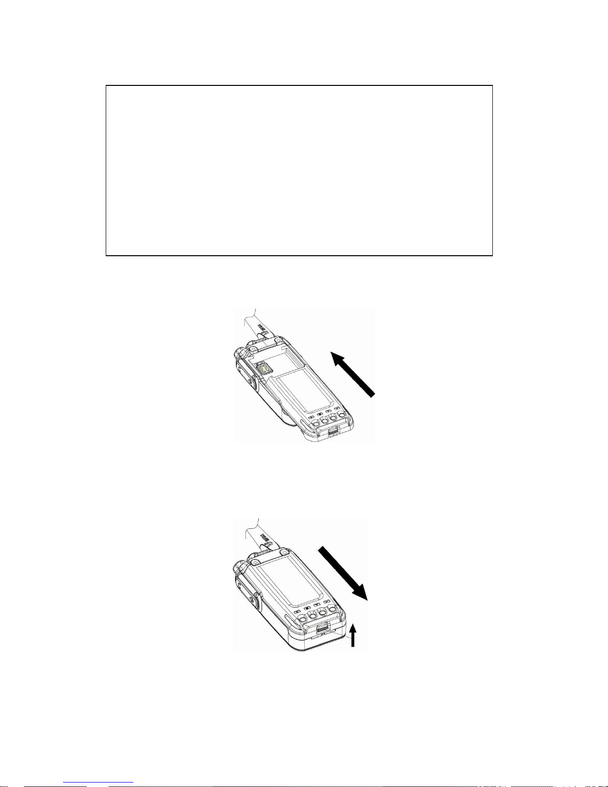
Attaching/Removing the Battery
Match the guides of the battery with the corresponding grooves on the upper rear of
the radio then press the battery until a click is heard to lock it in place.
To remove the battery, please turn the power off then press the release latch to
unlock the battery and pull the battery away from the radio.
Note: Don’t attach or remove the battery if the radio is turned on.
Warning
!
◆ Don’
t
short-circuit the batte
ry because
it might cause the ba
ttery
to
bu
rst
into flame or otherwise be damaged.
◆ Never a
tt
empt to remove the casing from batte
ry because you might be
exposed to caustic chemicals and you will damage the battery.
◆ Don’
t
throw the battery into fire or change it in an explosive area if you
value your life.

Li-ion battery features
New batteries are activated from factory. Please charge your battery before using
it. The maximum battery capacity and performance is achieved after three full
charge/ discharge cycles.
●The service life of batteries is determined by the number of Charge cycles. To
prolong battery life, do not charge more than necessary and do not try to charge
until the battery remaining capacity is low. To not keep it in the charger after the
battery is fully charged.
●To reduce self-discharge, please remove the battery fro m th e radio if you
do not plan on using it for a long time and store your battery in a cool, dry location.
●Charge your battery to about 50% of its capacity before you store it for a long
period of time to prevent a decrease in the batteries performance.
●As the battery is charged and discharged repeatedly, the battery capacity
decreases. Even if the battery is unused, the battery degrades. Storing the battery at
high temperature will shorten its lifecycle.
Charging the Li-ion battery
● When the battery power runs low the radio will send alert sounds. Please recharge
the battery at that time.
● Please only use the battery and charger specified by Connect Systems.
● When charging a battery attached to a radio, please turn the radio off.
● Please don’t remove the battery from the charger before fully charged, or the
battery could be damaged.
● Please remove the battery when the battery is fully charged. Do not keep the
battery in the charger to be trickle charged.
Note: While the battery is charged, the ambient temperature must be within 0~40 degrees
centigrade, Temperature out of that limit may reduce the working life or charging efficiency.
Charging Steps
1. Place the battery or the radio attached with a battery in the charger.
2. Plug the AC connector of the power supply into the outlet socket.
3. Making sure the battery is connected to the charger, the charging process initiates
when the charger indicator glows red.
4. The charger indicator glows green when the battery is fully charged.
Note: If the charger indicator will not glow, then the battery is not connected to the charger,
the battery is damaged, the charger is damaged, the power supply is damaged, the
temperature is out of limits, or the power supply is not connected to AC power.

Attaching the Speaker/Microphone
Open the accessory jack cover, then align the plug with the accessory jack and tighten the
screw on the plug.

Getting Acquainted
① Power switch/volume adjust keys
Turn clockwise to switch the radio power on, when the radio is turned on, rotate
clockwise to increased volume, counter- clockwise to decrease the volume. Turn
counterclockwise fully to switch the radio off.
② Channel Selector Knob
Turn the knob to select channel 1-16.
③ LED Indicator
1. When transmitting LED glows red;
2. When receiving LED glows green;
3. When un-programmed LED glows red;
4. When scanning LED flashes orange.
④ MIC
⑤ Left key
Press to move to the next step or store the setting.
⑥ MENU
Press to enter menu mode, you can select the desired menu item.
⑦ Selection Key
Press up or down/left or right to select the menu function item
⑧ Right key
Press to move back to the previous menu.

⑨ HOME key
Press to quickly return home screen.
⑩ Speaker
○11 Numerical
To input numbers and letters
○12 MIC-SP-USB Jack
Connect to optional speaker/MIC and USB programming cable.
○13 PTT key
Press and hold down the PTT key then speak into the microphone to transmit.
○14 Button 1
Press to activate the programmable function. (The detailed consult to basic
operation)
○15 Button 2
Press to activate the programmable function. (For details consult basic operation)

Basic Operation
LCD Icons
Signal Strength
H/L
High/Low Power
Digital Mode
Analog Mode
Private Call
Group Call
All Call
Scanning on
unread message
Inbox or Outbox Full
Message send successfully
Message send failed
Read Message
Unread Message Inbox
Missed Call
Keypad Locked
disable all tone alert
Emergency on
VOX on
Plug in earphone
Direct /Talk around Mode
Monitoring
Connect to Computer
Battery Capacity

Turning the power on /off
Rotate the power switch/volume control clockwise to turn the power on.
Rotate the power switch/volume control counter-clockwise to turn the power
off.
Note: If you activate “power on password” function via programming software,
each time you turn on radio, the 6 digit password must be entered. If you enter
the wrong password, the radio will restart automatically and you must enter
password again. If you enter the wrong password three times in a row, you
brick the radio and you must reprogram the radio to use it again. Please
enable power on password with due care.
Adjusting the volume
After the radio is powered on, you can rotate the power switch/volume control to
adjust the volume level. Rotate the knob clockwise to increase the volume or
rotate the knob counter-clockwise to decrease the volume.
Selecting a Channel
Turn the channel selector knob to select channel 1 to 16. Rotate the knob
clockwise to increase the channel number, or rotate the knob counter-clockwise
to decrease the channel number. If enabled, the radio channel number will be
audibly annunciated when you change the channel.
Note: If a channel is not programmed, the display says:”Unprogrammed Channel”, there
is an audible message saying “No Channel” and the LED indicator flashes red.
Selecting a Zone
The radio supports up to 64 zones each with a maximum of 16 channels. With all
zones used up to 1024 channels can be used. You may select a desired zone
through “zone” menu or setting “zone toggle” selection function to button 1 or
button 2. To select the zone, use the “Selection Key” to scrolling through the
zones and then when the proper zone is highlighted, press the “OK” key. If voice
enabled, the current radio channel number will be audibly annunciated when you
change the zone.
Call
Each digital channel may assign a contact and the assigned contact could be a
private call contact, a group call contact or an all call contact. To transmit on analog
channels, press and hold down the PTT key, wait for the LED indication to glow red
and then speak 3 to 4 centimeters away from the microphone.

Note: If the talk permit indication feature is set to “Digital”, “Analog” or “Digital &
Analog” and you press the PTT key, the radio will generate a momentary beep on
the speaker.

Private Call
If the feature “private call ACK” is enabled, when transmitting a private call, the radio
will monitor if current ID is available or not.
(1) If you assigned the Tx Contact parameter to be a private call contact for current
digital channel, pressing the PTT key will transmit a private call.
(2) If you go to the List Submenu in the Contacts menu and you select a private call
Contact, then pressing the PTT key will transmit a private call.
(3) If you go to the Manual Call Submenu in the Contacts menu and you enter a
private call number, then pressing the PTT key will transmit a private call.
(4) If you go to the Call Log menu and select a private call number you want to call,
then pressing the PTT key will transmit a private call;
(5) If you assign the One Touch Call key as private call, then pressing the PTT key
after you select that One Touch Call key will transmit a private call.

Group Call
(1)If you assigned the Tx Contact parameter to be a group call contact for current
digital channel, pressing the PTT key will transmit a group call.
(2)If you go to the List Submenu in the Contacts menu and you select a group call
Contact, then pressing the PTT key will transmit a group call.
(3)If you go to the Call Log menu and select a group call number you want to call,
then pressing the PTT key will transmit a group call;
(4)If you assign the One Touch Call key as group call, then pressing the PTT key
after you select that One Touch Call key will transmit a group call.
All Call
(1)If you assigned the Tx Contact parameter to be an all call contact for current
digital channel, pressing the PTT key will transmit an all call.
(2)If you go to the List Submenu in the Contacts menu and you select an all call
Contact, then pressing the PTT key will transmit an all call.
(3)If you go to the Call Log menu and select an all call number you want to call,
then pressing the PTT key will transmit an all call.
Receiving and responding to a call
On digital channel, when a private call is received, you may press the PTT key within
the preset time period to call back. If you do not respond to a received private call
within the preset time period, the radio will display the missed call icon. When a group
call is received, you may press the PTT key within the preset time period to call back.
If you do not respond to a received group call within the preset time period, the radio
will display the missed call icon. You cannot respond to an all call.
Note: With channel free indication feature enabled, when the PTT key is released, a
tone will be generated.

Button setting
You may program button1 and button2 for special functions as defined below. Each
key can be defined separately for differently functions depending on if you give the
key a short press or a long press.
Unassigned
This key is not assigned with any function
One Touch Call 1~6
Allow user to initiate digital group call, digital private call,
call alert or send preset message via the one touch call
function.
Manual Dial for Private
You can manually input the private call number for calling.
Emergency On
Allow user to make an emergency call.
Monitor
Enables and disables the monitor function
Backlight Auto On/Off
This function allows the user to have the backlight on
continuously or only on for five seconds after a key has
been pressed
Keypad Lock
Allows user to enable the keypad lock feature. If the
keypad lock is enabled user can only operate the PTT
key and side button. Press MENU and # key to
unlock.
Scan On/Off
Allow user to enable or disable the scan function.
All Alert Tones on/off
Allow user to enable or disable all alert tones
Battery Indicator
Indicates battery charge left
Short Message
Allows you to enter the message function menu
Zone Toggle
Allows you to enter the zone selection function
AD Switch
Selects between the Analog and Digital Modes
Contacts
Allow you to enter the Contacts menu
Radio Enable
Sends an enable command to a private call contact.
Radio Disable
Sends a disable command to a private call contact.
Radio Check
Sends a device check command to a private call contact
Remote Monitor
Allows you to remotely monitor another radio
High/Low Power
Allows user to switch between high and low power
Repeater/Talkaround
Allows radio to communicate through a repeater or speak
directly to another radio without a repeater.
Vox On/Off
Enables and disables the VOX function
Nuisance Delete
While scanning, allows you to remove a channel from the
scan list.
Permanent Monitor
Enables and disables the monitor function. Only works
with a long key press

Enhanced Scanning
Pressing this button will allow you to go to the enhanced
scanning mode defined by the Enhanced Scanning
parameters in the General Settings Page.
Enhanced Monitoring
Pressing this button will allow you to go to the enhanced
monitoring mode to allow you to receive all conversations
on that channel.
Enhanced Parameters
Pressing the Enhanced Parameter button will allow you to
go directly to a screen that will allow you to set all
parameters necessary for a digital or analog call.
Note:
For an analog channel, the following keys are useful: Unassigned, Monitor, Backlight
Auto On/Off, Keypad Lock, Scan On/Off, All Alert Tone on/off, Battery Indicator, Zone
Toggle, High/Low Power, Repeater/Talk Around on/off, Nuisance Delete, Permanent
M o ni t o r .

Functions and Operations
Digital channel( )
Contacts
Press the key to access the contact list. From the contacts, you can access
list members, add new contacts or manually dial.
1. Group Call( )
After selecting a group contact as shown below, pressing OK will then allow you
to select Details or Send Message. Selecting Details will allow you to see the
alias and the ID number for that contact. Selecting Send Message will then allow
you to send a new SMS or a predefined SMS

2. Private Call( )
After selecting a private contact as shown below, pressing OK will then allow you
to select Details, Call Alert, Send Message, Device Check, Remote Monitor,
Device Enable, Device Disable, Edit SMS, or Delete.
●Details: Allows you to see the Alias and ID number for the contact selected.
●Call Alert: Call alert is used for prompting an individual radio. You are asking
them to respond and transmit if communication is available. While receiving a
call alert command, the radio will generate alert tone.
●Send Message: Allows you to send a new SMS or a predefined SMS.
●Device Check: This function checks if the target radio is active without alerting
the target radio. When the target radio is active, the screen displays: “target
radio has replied”, while if the radio is unavailable, the screen displays: “fail!”
●Remote Monitor: Allow a user to send a "Remote Monitor" request to the
target radio. If the request is successful, you can enable the microphone of the
target radio and monitor its activities. The target radio has to be set to allow the
remote monitor command to be decoded.

●Device enable: Allow a user to send "Device enable" command to the target radio. If
request successful, killed radio will now be operational.
●Device Disable: Allow a user to send "Device Disable" command to the target radio.
If the target radio is lost or stolen, a user can use this function to disable the radio.
The disabled radio will still be able to receive the Device Enable command.
●Edit Contact: Modify the ID number or alias of a private call contact. Press”*” key to
delete last character entered or press “#” to switch input method. The numeric range
for the ID is 1~16776415. The Alias can have up to 16 characters.
●Delete: Deletes unwanted contacts from the address list. If private call contact is set
as channel Tx Contact or call number on one touch call, the contact will not be
deleted.
3. All Call ( )
After selecting an all contact as shown below, pressing OK will then allow you to
use that contact by pressing the PTT key.
4. Manual Dial
You can manually input the private call number for calling or sending call alert,
sending

message, device check, remote monitor, device enable or device disable.
5. New Contact
You can add a private call contact to the contact list. When editing the name,
press”*” key to delete, press “#1” to enter special characters, press “#0” to enter
a space and use the rest of the keys to enter the alphanumeric characters. The
name can be up to 16 characters. Next input number. The number can have a
range of 1~16776415. After the private call contact was successfully added, the
contacts list will show the new contact.
Scan
1. Scan On/Off
If current channel scan list contains at least 2 channels, at you may enable
the Scan On/Off feature. Scanning allows the device to search the scan list
connected to the current channel to locate qualified channel for receiving voice.
During scanning, the icon “ ”flashes. When activities are detected on a
channel, the radio will stay on the channel to receive current activities and the
icon“ ” will stop flashing. If you don’t want to receive activities on the channel,
press the programmed Nuisance Delete key
22

to remove the channel from the scan list temporarily. To exit the scanning
process, enter scan menu, switch channel or press the programmed Scan key.
Note: If the channel enables the feature “Auto Scan” via the programming
software, switching to that channel will enter scanning automatically. If button 1
or 2 is programmed as Scan on/off, press that button to enable scan feature.
2. View/Edit List
"View/Edit Member" allows a user to view the scan members, delete a member
from the scan list or add a member to the scan list. If you add a member, you
have to remember the list can contain no more than 16 channels. This feature
will not allow you to generate a new scan list or delete an existing scan list.
Digital and analog channel can appear in the same scan list.
23

Zone
The radio supports up to 64 zones and each zone supports 16 channels giving
a total of 1024 channel. Enter “Zone” menu to select a desired zone.
Messages
1.
New SMS
You can edit desired text message (140 characters at most) and send it to a
private call contact or a group call contact. When editing the name, press”*” key
to delete, press “#1” to enter special characters, press “#0” to enter a space
and use the rest of the keys to enter the alphanumeric characters. Press left or
right key to move input cursor. After the message is edited, you can select a
contact from the address list which the message is sent to or manually dial a
number to send to.
2.
Inbox
24

The Inbox can save up to 30 received messages. In the Inbox the unread
message displays: and the read message displays: . For each
message, you can choose to perform any of these operations: Reply, Forward
and Delete.
3.
Preset SMS
Via programming software, the user can save up to 10 text message entries
and each message can contain up to 140 characters. You can choose to edit
and send any entry.
Note: Preset text messages also can also be assign to one touch call.
Press the programmed key to send the message.
4.
Outbox
With the outbox menu, you can view if the message was sent successfully or
failed. The outbox can save up to 30 sent messages. If the sent message is
successful it displays and you can choose to forward or delete it. If sent
message unsuccessful, it displays ,and you can choose to resend,
forward or delete message.
25

5.
Delete All
This function is a convenient way to delete all message on the inbox or outbox.
Clear All will delete all messages on Inbox and Outbox at the same time. The
preset messages can’t be deleted.
Call Logs
1. Missed Call
The missed calls log can save up to 10 entries. When the memory for call logs
is full, the oldest entry will be deleted automatically. You can add the missed
call to the contact list or delete it.
2. Answered Calls
The answered calls log can save up to 10 entries. When the memory for call
logs is full, the oldest entry will be deleted automatically. You can add the
answered call to the contact list or delete it.
26

3. Outgoing Calls
The outgoing calls log can save up to 10 entries. When the memory for
outgoing call logs is full, the oldest entry will be deleted automatically. You can
add the outgoing call to contact list or delete it.
4. Clear Record
This function is convenient to delete Missed call logs Answered call logs or
Outgoing call logs, Clear All will delete all call logs at the same time.
Settings
1.
Settings
Allow a user to perform basic settings for the two-way radio.
27

●
Talk Around: When your repeater malfunctions or when the radio is out of
repeater’s range, you can continue to communicate in talk around mode. With
the enable talk around feature, the screen displays: and the TX frequency
will be the same as the RX frequency. If the channel is switched, the scan is
enabled, or the radio was restarted, the feature will be disabled.
Note:To enable this function, TX frequency should be different from RX
frequency, and the channel will set as allow talk around on the programming
software.
●Tone/Alerts: To sets alert tones for your radio. Tone alerts include settings of
all tones, call alert tone, message tone and keypad tone. If disabled, all alert
tones will be off except emergency tone.
●TX Power : Allow a user to change the power level between high and low
indicated by H and L on the display.
28
●Backlight: To set the backlight parameters, you can select on or automatic.
When you select automatic, the light will stay on for 5 seconds after a key is
pressed. If you select on, the light will stay on as long as the power is on.

●Boot Interface: Allow a user to enable or disable the introduction screen when
the power is first turned on. When the introduction screen is enabled, the display
will show the BF Logo and the device name. When the introduction screen is
disabled, the screen will only show the device name.
●Keypad Lock: Allow a user to enable or disable the keypad lock via the menu.
The Keypad locked is indicated by When the keyboard is locked, you can
only operate the PTT key, button 1 or button 2. Press “MENU” and ”#” key to
unlock.
●LED indicator: To enable or disable LED indication. While disabled all indicators
are turned off including the backlight of the LCD, the Rx Green Indicator, the Tx
Red indicator and the Orange Scan indicator. Please use this function with due
care because once it is disabled, it is difficult to enable because it is almost
impossible to read the screen.
29

●VOX: While this function is enabled you can enjoy hands-free communication.
The radio will automatically begin transmitting when you speak, and terminate
transmitting when you stop speaking with no need of PTT press. Allow user to
set the VOX level (level 1-8) and VOX delay(0.5~10seconds) via menu. VOX on
indicate by : .
Note: The VOX feature only is used if you are using a supported headphone.
●Power-on Password: If the power-on password feature is enabled via the programming
software, you can modify the password by this menu. First you need input old password
correctly and then input a new password twice.
Note: This menu is effective if power on password is set via programming software.
30
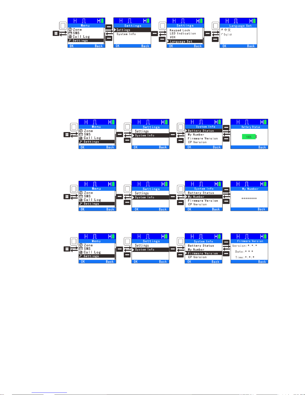
●Language: The radio supports two languages: Chinese and English.
2. System Info
With this option, you can view the basic information of your radio.
●Battery Status: To view the radio’s battery capacity. It’s convenient for user to
know the battery capacity so they can change or charge the battery before its
completely discharged.
●My Number: Allow a user to view the radio ID number, which is same as device
ID.
●Firmware version: View firmware version information.
●CP Version: To view CP version information.
31

Digital Emergency
In case of an emergency you can enter an emergency mode to ask for help.
There are three emergency types and three emergency mode available.
Emergency Type:
Regular: In emergency mode, the radio will give audible and visible indication;
Silent: In emergency mode, the radio won’t give any audible or visible indication;
Silent with Voice: In emergency mode, the radio won’t give any audible or visible
indication, but will receive voice.
Emergency Mode:
Alarm: In this mode, you can send alarm information and expect to get an ACK
back. It will do this for the maximum number of retries programmed before it will
exit the emergency mode.
Alarm with Call: You can press programmed ”Emergency On/Off” key to send
emergency information and then press PTT to transmit an emergency call.
Alarm with voice to follow: You can press programmed ”Emergency On/Off” key to
send emergency information, then you can speak into the microphone, allowing
your voice and background noise be transmitted automatically as you do not need
to press PTT Key.
32

Send Emergency Alarm
If the current channel has the emergency system enabled and the current
channel is used as the emergency revert channel, pressing the programmed “
emergency on/off” key sends alarm information, the LED indicator glows red, and
the radio displays icon as “regular” type.
Exit emergency mode
If the Emergency Type is Regular and in Emergency Alarm mode, the radio will
continue to send Alarm messages and stay in the alarm mode until it gets back
an ACK or the number of retries sent is at the maximum number programmed.
You can also exit the alarm mode by a long press of the Emergency on/off key. If
Emergency Type is silent or silent with voice, pressing the PTT key or a long
press of the programmed emergency key will exit the emergency mode.
Receive Emergency Information
When the feature” emergency alarm indication” is enabled, if received emergency
information, the radio displays icon , the transmitter’s ID and name, an alarm
tone will sound. To exit the emergency mode, long press the programmed
emergency key.
Analog Channel( )
In analog mode, the radio only supports three basic operations. The first is the
scanning, the second is zone and the third is settings. The scan and zone
features are the same as in the digital mode. The radio settings is the same as
digital except squelch level has been added.
33

●Squelch Level: In the analog mode, this feature allows you to adjust the
squelch threshold required for the radio to un-mute. You can set SQL1~9, Level
3 is the default.
CTCSS/CDCSS
In analog channel, you can set unique CTCSS tones or CDCSS codes to
guarantee the privacy of your communication. If CTCSS tone or CDCSS code
has been set in the current channel, a matching CTCSS tone or CDCSS code is
required for the radio to receive an incoming signal. You can select a CTCSS
tone from the standard CTCSS tone table or a DCS Code from the standard
CDCSS code table.
Set the encode and decode parameters in the Channel screen.
●Decode: Only when receiver receives a call containing matching the decode,
you can hear the call. If you set it to “None”, then the radio will hear all CTCSS
tones and CDCSS Codes with the disadvantage that you will also hear all noise
and calls made for someone else.
●Encode: Signal that you transmit will only be heard by parties whose
CTCSS/CDCSS signaling matches your transceiver.
Note: The radio will accept non-standard CTCSS codes in analog mode.
34
Voice Encryption
The voice encryption can encrypt your audio signals to guarantee the privacy of
your communication. This feature is setup in the programming software. The
user can select encryption type as static or dynamic. If the encrypt feature is
enabled, the transmitter and receiver must be set as the same encryption type
and same encryption key, otherwise the receiver is muted.
Note: This feature is effective only on digital channel.
Time Out Timer (TOT)
The purpose of TOT is to prevent any user from occupying a channel for an
extended period and preventing the radio from overheating. If a channel is busy,
the time will be shorter. If the preset time expires, the radio will generate beep

and terminate transmission automatically. With the programming software, you
can set TOT between 15-495 seconds.
TX Permission
Digital Channel
This feature called “Admit Criteria” and found on the Channel screen can restrict
the channel from transmitting if it is already in use. There are three options
available: always, color code free, channel free, if choose always, whenever the
PTT key is pressed the radio will transmit. If choose color code free, you will be
unable to transmit on the channel if the color code is already in use; If choose
channel free, you will be unable to transmit on the channel if it is already in use. If
the channel is busy, pressing the PTT key will generate a warning tone.
35

Analog Channel
This feature called “BCL” (Busy Channel Lockout) and found on the channel screen
can restrict the channel from transmitting if it is already in use. There are three
options available: off, carrier, CTCSS/CDCSS, if choose Off, whenever the PTT key
is pressed the radio will transmit. If choose carrier, you will be unable to transmit on
the channel if the channel is being used by others. If choose CTCSS/CDCSS, you
will be unable to transmit on the channel if it is already in use and the
CTCSS/CDCSS code in use. If the channel is busy, pressing the PTT key will
generate a warning tone.
Battery Saver
This function allows an idle radio to enter automatically a battery saver mode. This
mode will extend battery service life, but response time may be delayed. You can set
battery saver time ratio as : 1:1, 1:2, 1:3 or 1:4 The larger the second number, the
more power is saved and the longer the battery will last. This feature is found in
General Settings of the programmable software.

Low Battery Warning
When your battery gets low, the LED indicator glows red and and a warning message
of “Please Charge” will be annunciated. Please replace the battery or charge the
battery. The radio will turn off automatically while battery is too low. This feature is
found in General Settings of the programmable software.

CTCSS Standard Frequency Table
CTCSS
No.
Fre.
[Hz]
CTCSS
No.
Fre.
[Hz]
CTCSS
No.
Fre.
[Hz]
CTCSS
No.
Fre.
[Hz]
1
67.0
11
94.8
21
131.8
31
186.2
2
69.3
12
97.4
22
136.5
32
192.8
3
71.9
13
100.0
23
141.3
33
203.5
4
74.4
14
103.5
24
146.2
34
210.7
5
77.0
15
107.2
25
151.4
35
218.1
6
79.7
16
110.9
26
156.7
36
225.7
7
82.5
17
114.8
27
162.2
37
233.6
8
85.4
18
118.8
28
167.9
38
241.8
9
88.5
19
123.0
29
173.8
39
250.3
10
91.5
20
127.3
30
179.9

CDCSS Standard Code Table
CDCSS
NO
Positive
Code
Negative
Code
CDCSS
NO
Positive
Code
Negative
Code
CDCSS
NO
Positive
Code
Negative
Code
1
D023N
D023I
29
D174N
D174I
57
D445N
D445I
2
D025N
D025I
30
D205N
D205I
58
D464N
D464N
3
D026N
D026I
31
D223N
D223I
59
D465N
D465N
4
D031N
D031I
32
D226N
D226I
60
D466N
D466I
5
D032N
D032I
33
D243N
D243I
61
D503N
D503I
6
D043N
D043I
34
D244N
D244I
62
D506N
D506I
7
D047N
D047I
35
D245N
D245I
63
D516N
D516I
8
D051N
D051I
36
D251N
D251I
64
D532N
D532I
9
D054N
D054I
37
D261N
D261I
65
D546N
D546I
10
D065N
D065I
38
D263N
D263I
66
D565N
D565I
11
D071N
D071I
39
D265N
D265I
67
D606N
D606I
12
D072N
D072I
40
D271N
D271I
68
D612N
D612I
13
D073N
D073I
41
D306N
D306I
69
D624N
D624I
14
D074N
D074I
42
D311N
D311I
70
D627N
D627I
15
D114N
D114I
43
D315N
D315I
71
D631N
D631I
16
D115N
D115I
44
D331N
D331I
72
D632N
D632I
17
D116N
D116I
45
D343N
D343I
73
D654N
D654I
18
D125N
D125I
46
D346N
D346I
74
D662N
D662I
19
D131N
D131I
47
D351N
D351I
75
D664N
D664I
20
D132N
D132I
48
D364N
D364I
76
D703N
D703I
21
D134N
D134I
49
D365N
D365I
77
D712N
D712I
22
D143N
D143I
50
D371N
D371I
78
D723N
D723I

23
D152N
D152I
51
D411N
D411I
79
D731N
D731N
24
D155N
D155I
52
D412N
D412I
80
D732N
D732N
25
D156N
D156I
53
D413N
D413I
81
D734N
D734I
26
D162N
D162I
54
D423N
D423I
82
D743N
D743I
27
D165N
D165I
55
D431N
D431I
83
D754N
D754I
28
D172N
D172I
56
D432N
D432I

Specifications
General
Frequency range
UHF:400-480MHz/450-520MHz/350-390MHz
Channel Capacity
1024
Zones
64
Channel Spacing
12.5KHz/25KHz
Operating Voltage
DC 7.4V(±20%)
Battery capacity
1800 mAh
Battery Life(5/5/90)
High TX Power: Digital 16 hours; Analog 12 hours
Power Save Mode: Digital 20 hours; Analog 16 hours
Frequency Stability
±1.5ppm
Antenna Impedance
50Ω
Dimensions (L×W×H)
56(L)* 32(W)* 109 (H)mm
Weight
239g(include battery)
Transmitter
RF Output Power
High Power:4.5W
Low Power:1.0W
4FSK Modulation
12.5kHz only data:7K60FXD
12.5kHz data and audio:7K60FXE
FM Modulation
12.5 kHz:8K50F3E;
25 kHz:16KΦF3E;
41

Modulation Limiting
+/- 2.5kHz @ 12.5kHz;
+/- 5kHz @ 25kHz
FM Noise
-40dB
Conducted Emission
-36 dBm≤1GHz/-30 dBm≥1GHz
Adjacent Channel Power
≤-60dB
Audio Response
+1/-3 dB
Audio Distortion
3%
Digital Voice coder Type
AMBE+2
TM
Receiver
Digital Sensitivity
5% BER:0.25 uV
Analog Sensitivity
0.25 uV (12 dB SINAD)
Intermodulation
60dB
Adjacent Channel Selectivity
60 dB
Spurious Response Rejection
60 dB
FM Noise
-40dB
Audio Response
+1/-3 dB
Audio output power
1.5W
Audio Distortion
3% (Typical)
Conducted Spurious Emission
-57dBm
Environmental Specifications
Operating Temperature
-20℃—+60℃
Storage Temperature
-30℃—+85℃
42

Humidity
MIL-STD-810C/D/E/F Standard
Vibration & Shock
MIL-STD-810C/D/E/F Standard
Dustproof & waterproof
IP54
Statement
Our Company tries to make an accurate and complete manual. If you have any
question, you can contact us and we will give you an answer. All the above
specifications and designs are subject to change without prior notice due to
continuous development.

Summary of Radio Menu Functions
Contacts
List
Group contacts
Details
Send Message
New SMS
Preset SMS
Private contacts
Details
Call Alert
Send Message
New SMS
Preset SMS
Device Check
Remote Monitor
Device Enable
Device Disable
Edit SMS
Delete
Manual Dial
New Contact
Scanning
Turn On/Off
View/Edit List
View/Delete Member
Add Scan Channel
Zone
SMS
New SMS
Inbox
Preset SMS
Outbox
Delete All
In Box Delete
Outbox Delete
Delete All
Call Log
Missed Calls
Answered Calls
Outgoing Call
Clear Record
Settings
Settings
Talk Around
Tone/Alert
All Tones
Call Alert Tone
Message Tone
Keypad Tone

Tx Power
Backlight
Boot Interface
Keypad Lock
Led Indication
VOX
VOX Level
VOX Delay
Language Set
Squelch Level (Not currently available)
Device ID
System Info
Battery Status
Firmware Version
CP Version

Enhanced Scanning
The radio allows you to set the following parameters for scanning:
Type: The radio can be set to scan either Digital channels or Analog Channels. The type
is set by the channel you are on. If you are on an analog channel it will only scan analog
channels. If you are on a digital channel, you will only scan digital channels.
Min Frequency: This is the frequency the radio starts scanning. Scanning is from the
minimum frequency to the maximum frequency. We will set the default in the UHF version
to 420 MHz and the VHF version to 144 MHz.
Max Frequency: This is the frequency it stops scanning. We will set the default in the UHF
version to 450 MHz and the VHF version to 147.99 MHz.
Channel Spacing. This is the spacing between channels. In HF radios there is often
continuous tuning. At the VHF and UHF bands, the tuning is channelized because the
hardware is designed to only work with either 12.5 KHz spacing or 25KHz spacing. We set
the default in this radio to 12.5 KHz.
Enhanced Scanning Button: This defines which button is used to start the scanning mode.
We set the default to the top button and quick press.
To start the Enhanced scanning mode, press the appropriate button and you will get a
screen on the radio as shown below.

When it gets to an active channel, the display will show as follows for a digital signal.
To lock in that information, press the lock soft key just below the lock prompt on the
display. This will now allow you to quickly get on the air by just pressing the PTT key. The
Tx frequency is determined by the Rx to Tx Offset parameter in the CPS.
Once the Lock key is pressed, the following screen will appear.
To scan to the next frequency, press the Unlock softkey.

ENHANCED PARAMETERS
The radio allows you to set the following parameters for Enhanced Parameters:
Enhanced Parameters Button: This defines which button is used to start the enhanced
parameter mode. We set the default to the bottom button and quick press.
To start the Enhanced Parameter mode, press the appropriate button and you will get a
screen on the radio as shown below if your radio was on a digital channel.
To navigate to the different parameters, you use the left and right selection keys. Once
you are on the parameter you either use the up and down selection keys or the numeric
keypad to enter the data, depending on which parameter you want to change.
The CC is changed with the selection key. The minimum value is 0 and the maximum
value is 15
The Slot is changed with the selection key. Your choice is Slot 1 or Slot 2.
The Type could be selected as P, G, A, or N. standing for private, group, All, or None
respectively. The selection key is used for selecting your choice.
The TxContact is entered with the Numeric keypad
The Tx and Rx frequencies are entered with a direct entry by the numeric keypad.
Once you changed the information as necessary you then press the Lock softkey and the
information is ready to use on the air. After the lock softkey is pressed the following
screen appears.
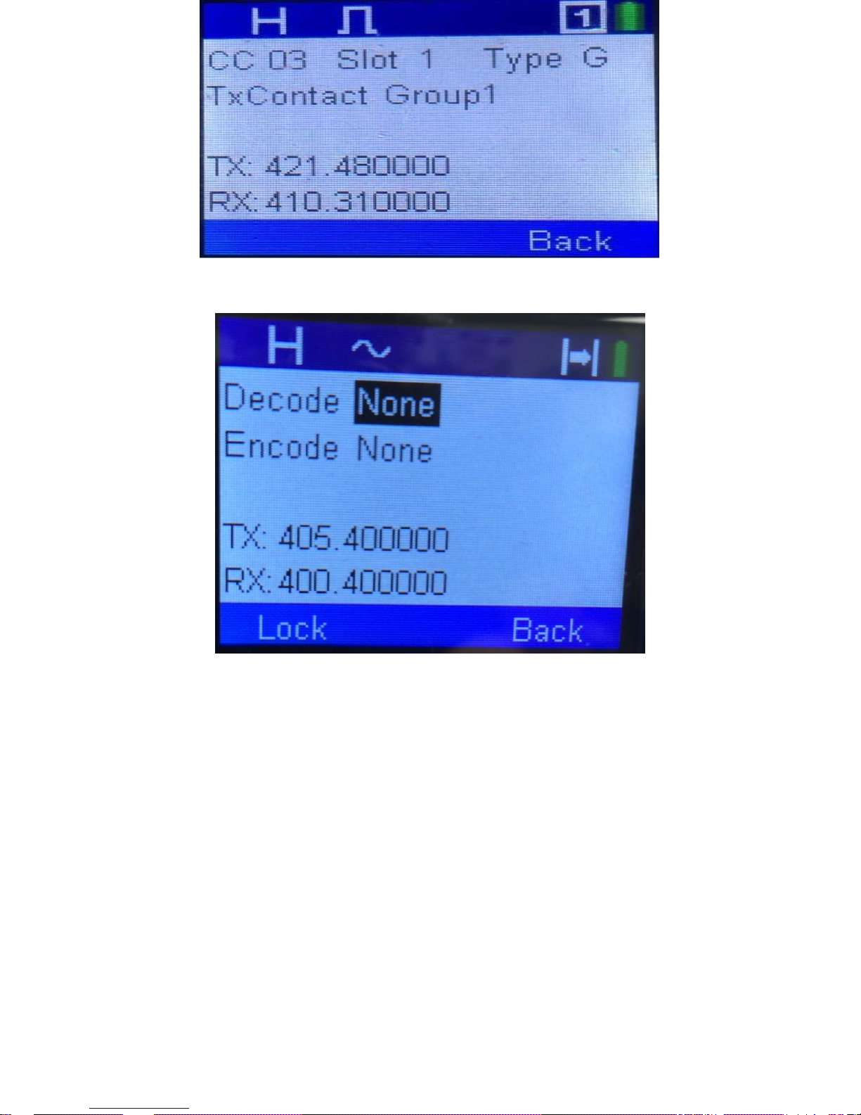
If your radio was on an analog channel, then the opening screen would be as follows:
You use the up and down selection key to select the different CTCSS or DCS parameters
in the Decode and Encode fields.
The starting screen for the enhanced parameters should be as follows:
1. If you change the channel switch or you first turn on power, the screen should be
whatever is associated with the channel.
2. If you locked in enhanced scanning, then whatever was used in scanning should be
on this screen.
3. If you locked in Enhanced Monitor, then whatever was used in enhanced monitor
should be on this screen.
4. If you locked in Enhanced Parameter, then whatever was used in enhanced
parameter should be on this screen.

ENHANCED MONITOR
The radio allows you to set the following parameters for Enhanced monitor:
Enhanced Monitor Button: This defines which button is used to start the enhanced monitor
mode. We set the default to the top button and long press.
To start the Enhanced Monitor mode, press the appropriate button and you will get a
screen on the radio as shown below if your radio was set to a digital channel.
If you hear a conversation you like on that channel press the lock key and you are now
ready to use the radio. After you press the lock key you will get the following screen:

If your radio was on an analog channel and you entered the enhanced monitor mode, you
would get the following screen.
Finding Key Parameters
So you got a radio and now you want to know where you can find the various
parameters to set up the radio.
The first place to find analog and digital repeaters is a website called
www.repeaterbook.com. That will show all the repeaters in the world. Note that
many of the repeaters are closed and they do not want outsiders using them.
However if you only want DMR repeaters then go to www.dmr-marc.net or
www.cqdmrmap.com/. This last one is interesting because the map shows which
network the different repeaters are on.
There is a standard for UHF repeaters in that the receive frequency is always 5 MHz
from the transmit frequency. There is no agreement in the amateur community if the
transmit frequency is greater than the receive frequency or the transmit frequency is
less than the receive frequency.
There is no agreement on color codes but most repeaters have set the color code to 1.
 Loading...