

Connects2 CTUPO02 User Manual
CTUPO02
Infodapter Interface
for Porsche Vehicles
ii
ix
iiiiv
i
viii
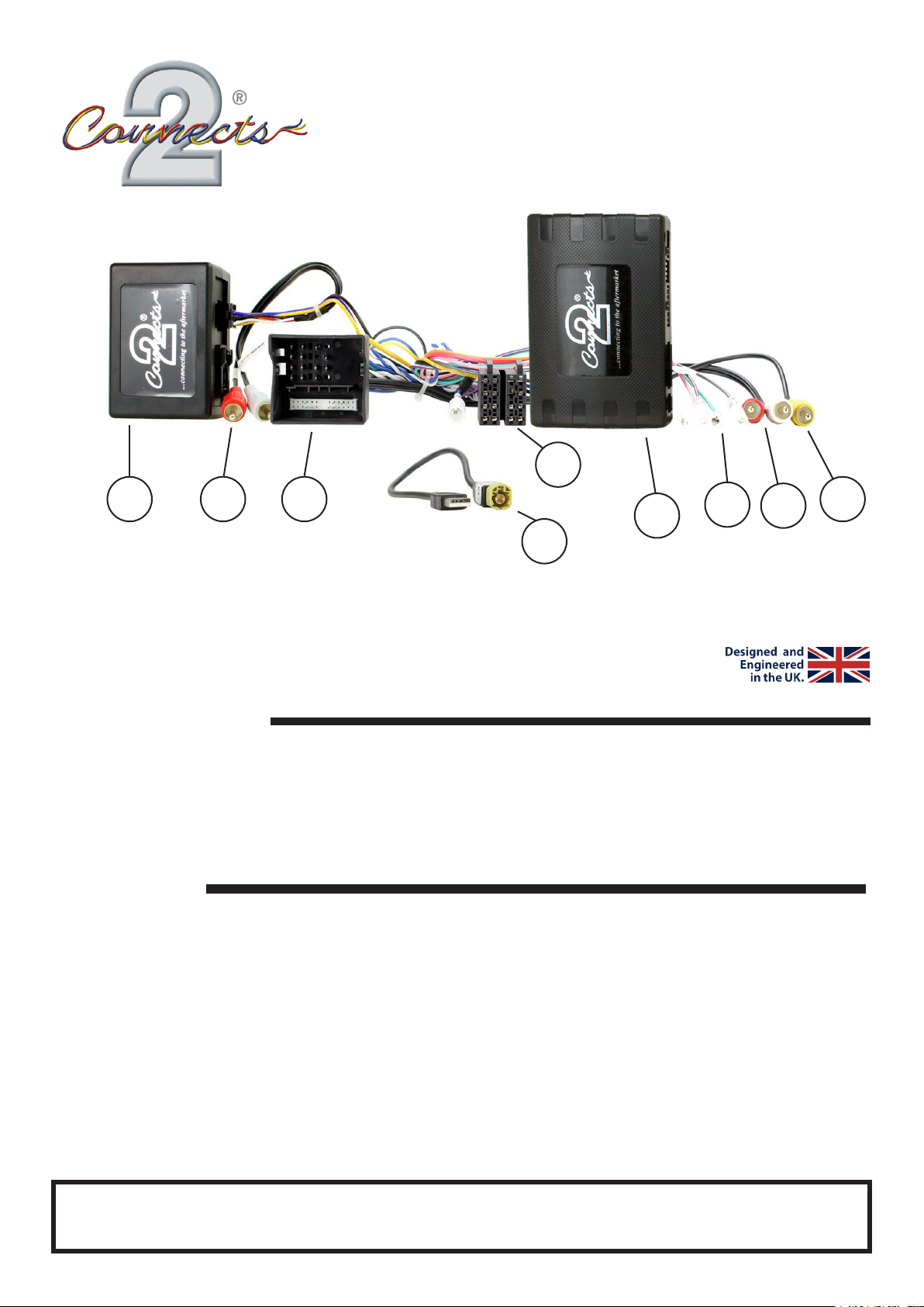
i. Interface Box
ii. ISO Connector (16 Pin)
iii. Quadlock Connector (40 Pin)
iv. RCA Amplier (Red/White)
v. RCA AUX (Red/White)
APPLICATION
Porsche Panamera 2009 - 2016
Porsche Macan (95B) 2014 - 2016
Porsche Cayenne 2011 - 2016
For ber-amplied vehicles with MOST 25 systems and quadlock connectors.
vi. RCA Camera (Yellow)
vii. Flying Wires
viii. USB Retention Harness
ix. Amp Retention Interface
Note: Application data is subject to change at any time
FEATURES
• Retains Steering Wheel Control Functionality
vii
v
vi
• Retains Phone Button Functionality
• Retains MOST 25 Fiber Amplied System
• Retains USB and AUX Inputs
• Retains Reversing Camera
• Retains Parking Sensor Audio and OEM Parking Sensor Graphics
• Provides Outputs for Park Brake, Reverse Gear, Speed Pulse, Mute & Amp Remote
• Updateable via USB (contact supplier for more information)
The information provided in this document is subject to change without notice due to manufacturer changes and/or improvements to the product/s. This
instruction manual is based on documented data and research. The manufacturer of this product cannot be held responsible for any changes made to the
vehicle by the manufacturer or damages that may occur through the installation of this product in accordance with the steps outlined herein.
DISCLAIMER
CTUPO02_IG_en-GB_v1
PRIOR TO INSTALLATION
1 2 3 4
Read the manual prior to installation. Technical knowledge is necessary for installation. The place of installation
must be free of moisture and away from heat sources. Please ensure that the correct tools are used during the
installation to avoid damage to the vehicle or product. Connects2 can not be held responsible for the installation
of this product.
Note: The aftermarket stereo being installed must have female RCA connectors in order for this product to
function correctly
WIRING KEY
IN ISO CONNECTOR
Purple Right Rear Speaker +
Purple/Black Right Rear Speaker Green Left Rear Speaker +
Green/Black Left Rear Speaker Grey Right Front Speaker +
Grey/Black Right Front Speaker White Left Front Speaker +
White/Black Left Front Speaker -
ADDITIONAL CONNECTIONS
Pink Speed Pulse
Green Park Brake
Purple/White Reverse Gear
Blue/White Amp Remote
Grey Mute
Red/White RCA (AUX) AUX Input Retention
Red/White RCA (Speaker) Amplier/Audio Retention
Yellow RCA Reversing Camera Retention
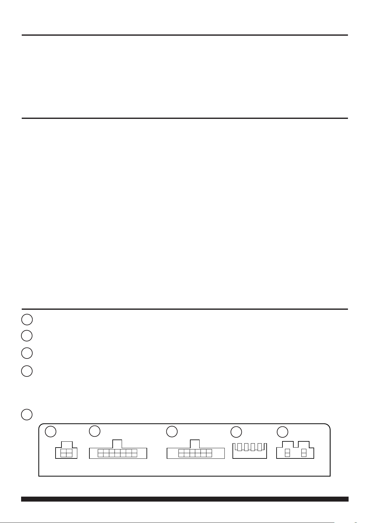
INTERFACE CONNECTIONS
Reverse Camera Extension Harness InputReverse Camera Extension Harness Input
1
Yellow Permanent 12V
Black Ground
Red Ignition 12V
Orange Illumination
Power Harness InputPower Harness Input
2
Head Unit Connection (Patch) Lead InputHead Unit Connection (Patch) Lead Input
3
DIP Switch 1 - ‘ON’ for Pioneer, ‘OFF’ for other brand head unitsDIP Switch 1 - ‘ON’ for Pioneer, ‘OFF’ for other brand head units
4
DIP Switch 2 - ‘ON’ for PAL reversing camera, ‘OFF’ for NTSC reversing camera (Default is ‘OFF’/NTSC)DIP Switch 2 - ‘ON’ for PAL reversing camera, ‘OFF’ for NTSC reversing camera (Default is ‘OFF’/NTSC)
DIP Switch 3 - Change from ‘OFF’ to ‘ON’ and back to reset screen settings to factory defaults. DIP Switch 3 - Change from ‘OFF’ to ‘ON’ and back to reset screen settings to factory defaults.
Note: During this procedure, the screen background will change to red and no settings adjustments can be made.Note: During this procedure, the screen background will change to red and no settings adjustments can be made.
DIP Switch 4 - Not UsedDIP Switch 4 - Not Used
Not usedNot used
5
1
2
3
4 5
2
CTUPO02_IG_en-GB_v1

INSTALLATION GUIDE
Before installing the interface, the factory stereo must be removed and disconnected. To do this, please consult the vehicle
owner’s manual/handbook or contact a tting professional.
A stereo connection (patch) lead is also required for the installation of this interface (supplied seperately). Please ensure
that you have the correct lead before proceeding. For universal patch leads, prepare the wiring loops in accordance with the
instruction manual supplied with the product before installation.
1. Connect the 12 Pin connector from the stereo connection (patch) lead to the interface box
2. Connect the opposite end of the stereo connection (patch) lead to the steering wheel control input on the back of
the aftermarket stereo
NOTE: This may be a 3.5mm jack connector or a wired input depending on the brand of aftermarket stereo being tted.
Please consult the aftermarket stereo installation manual for further information on where to make the connection
IMPORTANT: THIS STEP MUST BE COMPLETED BEFORE CONNECTING POWER TO THE INTERFACE.
FAILURE TO DO SO MAY RESULT IN A LACK OF FUNCTIONALITY AND THE NEED TO REINSTALL THE PRODUCT
!
3. Connect the 14 Pin connector from the supplied wiring loom to the interface box
4. Connect 4 Pin camera extension harness to the interface box
5. Connect the amplier retention interface to the 8 Pin connector on the supplied wiring loom
See Wiring Diagram on Pg.4 for more information
6. Remove the plastic dust cover from the amplier retention interface and plug in the vehicle’s ber amplier connection
7. Connect the power/speaker ISO connector to the power/speaker ISO connector at the rear of the aftermarket stereo.
8. Connect ying wires from the main wiring harness to the head unit. See ‘Additional Connections’ for more information. Note that the Amp Remote and Reverse Gear wires must be connected for the interface to function correctly.
9. Connect the male red and white RCA connectors (speaker) to the front line outputs on the rear of the aftermarket
stereo to retain vehicle amplier audio
10. Connect the male red and white RCA connectors (AUX) to the rear of the aftermarket stereo to retain the OEM
AUX input
11. Connect male yellow RCA from the camera extension harness to the reverse camera input of the aftermarket head
unit.
a) To retain functionality of the factory camera - connect the female yellow RCA from the camera extension harness to
the male yellow RCA from the main wiring harness.
b) If tting an aftermarket camera - connect the male yellow RCA from the aftermarket camera to the female yellow
RCA from the camera extension harness.
12. Connect the USB retention harness to the vehicle and to the back of the aftermarket stereo to retain the OEM USB
input
13. Connect the quadlock connector on the supplied harness to the quadlock connector from the vehicle
14. Test stereo and steering wheel control functionality for correct operation before reassembling the
vehicle dashboard. If steering wheel control functions are unresponsive, please uninstall the interface and wiring and
reinstall carefully in accordance with the above steps.
For further help and support, please contact us directly at support.connects2.com/tickets/technical and ll out a support
ticket with the full details of your issue.
Need help? Visit support.connects2.com/tickets/technical
3
CTUPO02_IG_en-GB_v1
 Loading...