


Connection Technology System FWR531X User Manual

FWR5-3105 Series
Residential Gateway
Network Management
User’s Manual
Version 0.93
1

Trademarks
Contents are subject to revision without prior notice.
All other trademarks remain the property of their respective owners.
Copyright Statement
Copyright © 2016, All Rights Reserved.
This publication may not be reproduced as a whole or in part, in any way whatsoever unless prior consent
has been obtained from Company.
FCC Warning
This equipment has been tested and found to comply with the limits for a Class-A digital device, pursuant to
Part 15 of the FCC Rules. These limitations are designed to provide reasonable protection against harmful
interference in a residential installation. This equipment generates uses and can radiate radio frequency
energy. If this equipment is not installed properly and used in accordance with the instructions, may cause
harmful interference to radio communications. However, there is no guarantee that interference will not
occur in a particular installation. If this equipment does cause harmful interference to radio or television
reception, which can be determined by turning the equipment off and on, the user is encouraged to try to
correct the interference by one or more of the following measures:
Reorient or relocate the receiving antenna.
Increase the separation between the equipment and receiver.
Connect the equipment into a different outlet from that the receiver is connected.
Consult your local distributors or an experienced radio/TV technician for help.
Shielded interface cables must be used in order to comply with emission limits.
Changes or modifications to the equipment, which are not approved by the party responsible for
compliance, could affect the user’s authority to operate the equipment.
Copyright © 2016 All Rights Reserved.
Company has an on-going policy of upgrading its products and it may be possible that information in this
document is not up-to-date. Please check with your local distributors for the latest information. No part of
this document can be copied or reproduced in any form without written consent from the company.
Trademarks:
All trade names and trademarks are the properties of their respective companies.
2

Revision History
Version Firmware Date Description
0.90 0.99.06 20160831 First Release
Add QoS (Section 3.8)
0.91 0.99.0N 20170208
0.93 0.99.0N 20170914 Modify the device name.
Add WPS (Section 3.5.5)
Revise MAC Access Filter (Section
3.5.4)
3

Table of Contents
1.INTRODUCTION.....................................................................................................................................6
1.1ManagementOptions..............................................................................................................................................................7
1.2InterfaceDescriptions...............................................................................................................................................................7
1.3ConnectingtheResidentialGateway........................................................................................................................................8
2.CommandLineInterface(CLI)...............................................................................................................8
2.1RemoteConsoleManagement‐Teln e t ....................................................................................................................................8
2.2NavigatingCLI..........................................................................................................................................................................9
2.2.1GeneralCommands..........................................................................................................................................................9
2.2.2QuickKeys......................................................................................................................................................................10
2.2.3CommandFormat...........................................................................................................................................................10
2.2.4LoginUsername&Password..........................................................................................................................................11
2.3UserMode..............................................................................................................................................................................12
2.3.1PingCommand...............................................................................................................................................................12
2.3.2Tracero u teCommand.....................................................................................................................................................13
2.4PrivilegedMode......................................................................................................................................................................13
2.4.1Copy‐cfgCommand........................................................................................................................................................13
2.4.2FirmwareCommand.......................................................................................................................................................15
2.4.3PingCommand...............................................................................................................................................................16
2.4.4ReloadCommand...........................................................................................................................................................16
2.4.5Tracero u teCommand.....................................................................................................................................................16
2.4.6WriteCommand.............................................................................................................................................................17
2.4.7ConfigureCommand.......................................................................................................................................................17
2.4.8ShowCommand.............................................................................................................................................................17
2.5ConfigurationMode...............................................................................................................................................................18
2.5.1EnteringInterfaceNumbers...........................................................................................................................................19
2.5.2NoCommand..................................................................................................................................................................19
2.5.3ShowCommand.............................................................................................................................................................19
2.5.4ApplicationsCommand..................................................................................................................................................20
2.5.5InterfaceCommand........................................................................................................................................................22
2.5.6IPCommand...................................................................................................................................................................38
2.5.7ManagementCommand.................................................................................................................................................43
2.5.8NTPCommand................................................................................................................................................................46
2.5.9QoS.................................................................................................................................................................................48
2.5.10SecurityCommand.......................................................................................................................................................49
2.5.11SNMPCommand..........................................................................................................................................................57
2.5.12SyslogCommand..........................................................................................................................................................60
2.5.13System‐InfoCommand.................................................................................................................................................61
2.5.14UserCommand.............................................................................................................................................................62
2.5.15VLANCommand...........................................................................................................................................................63
3.WEBMANAGEMENT...........................................................................................................................64
3.1TheConceptofIPaddress......................................................................................................................................................64
3.2StartConfiguring....................................................................................................................................................................64
3.3IntroductiontoSub‐Menus.....................................................................................................................................................66
3.4Setup......................................................................................................................................................................................67
3.4.1SystemInformation........................................................................................................................................................68
3.4.2BasicSetup.....................................................................................................................................................................71
3.4.3DDNS...............................................................................................................................................................................79
3.4.4NetworkSetup................................................................................................................................................................81
3.4.5RoutingSetup.................................................................................................................................................................84
4

3.5WiFi(ForWiFiModelOnly)....................................................................................................................................................86
3.5.1WirelessSetup................................................................................................................................................................87
3.5.2WirelessSecurity............................................................................................................................................................92
3.5.3WirelessAdvanced.......................................................................................................................................................104
3.5.4MACAccessFilter.........................................................................................................................................................108
3.5.5WPS..............................................................................................................................................................................110
3.6Security.................................................................................................................................................................................110
3.6.1Firewall.........................................................................................................................................................................110
3.6.2PacketFilter..................................................................................................................................................................111
3.6.3URLFilter......................................................................................................................................................................116
3.6.4VPNPassThrough.........................................................................................................................................................117
3.6.5UPnP.............................................................................................................................................................................118
3.6.6DDoS.............................................................................................................................................................................118
3.7Application...........................................................................................................................................................................122
3.7.1PortForwarding............................................................................................................................................................122
3.7.2DMZ..............................................................................................................................................................................125
3.8QoS.......................................................................................................................................................................................127
3.8.1QoSPriority..................................................................................................................................................................127
3.8.2QoSRatelimiter............................................................................................................................................................132
3.9IPTV......................................................................................................................................................................................134
3.9.1IGMPControl................................................................................................................................................................135
3.10Management......................................................................................................................................................................136
3.10.1DHCPAutoProvision..................................................................................................................................................137
3.10.2SNMP..........................................................................................................................................................................138
3.11Administration....................................................................................................................................................................142
3.11.1DeviceAccess.............................................................................................................................................................143
3.11.2InterfaceManagement...............................................................................................................................................145
3.11.3Time............................................................................................................................................................................147
3.11.4Syslog..........................................................................................................................................................................149
3.11.5Diagnostics.................................................................................................................................................................151
3.11.6UserPrivilege..............................................................................................................................................................152
3.11.7Backup/Restore..........................................................................................................................................................154
3.11.8FactoryDefault...........................................................................................................................................................155
3.11.9FirmwareUpgrade......................................................................................................................................................158
3.11.10Save&Logout.............................................................................................................................................................161
3.12Status..................................................................................................................................................................................162
3.12.1WAN............................................................................................................................................................................162
3.12.2LAN.............................................................................................................................................................................163
3.12.3WiFi............................................................................................................................................................................165
3.12.4RoutingTabl e ..............................................................................................................................................................167
3.12.5PortStatus..................................................................................................................................................................168
3.12.6EventLog....................................................................................................................................................................169
3.13Wizard................................................................................................................................................................................169
4.SNMPNETWORKMANAGEMENT......................................................................................................171
APPENDIXA:SetUpDHCPAuto‐Provisioning........................................................................................172
APPENDIXB:DHCPText Sample............................................................................................................177
5

1. INTRODUCTION
Thank you for purchasing the Wireless Home Gateway which is designed to aim at FTTX
applications and indoor use only due to RF device.. This Wireless Home Gateway provides four
TP ports for LAN applications, one fiber optic or TP port for WAN, wireless function provides users
not only more flexible ways to enjoy bandwidth-intensive services but also more secure
internetwork connections by implementing packet or URL filtering policies.
The wireless function of this Gateway conforms to IEEE 802.11n standards that can provide speed
rate up to 30Mbps or 300Mbps when used with other 802.11n wireless products (the speed rate
varies depends on the model that your purchase). To enhance wireless connections to reach
further, the antennas, dispersing the same amount of power in all directions, can be used to
receive and deliver stable and high-gain transmissions. The Wireless Home Gateway also
supports WPA/WPA2/WPA-Mixed authentication methods and 64/128-bit data encryption to
implement strict security protection so as to prevent your wireless networks from unauthorized
uses or possible malicious attacks. Other security mechanisms provided that can protect your
network including the uses of disabling SSID broadcast function, MAC filtering, URL filtering,
DDoS protection.
The Wireless Home Gateway is mainly dedicated to the FTTX broadband service providers who
look for a way of delivering multiple IP services to the home users. The fiber optic port supports
connection distance from 2KM to 20KM or further than 100KM by using multi-mode optical fiber,
single-mode optical fiber (SMF), or bi-direction SMF. The transmission distance varies depending
on the fiber transceiver that your purchase. For detailed information about fiber transceiver, please
refer to Fiber Transceiver Information PDF in Documentation CD-ROM. To easily manage and
maintain the device, advanced network settings are configurable via Web-based Management
such as Firmware upgrade. The featured NAT and DHCP server functions also allow you to use a
hub or switch to establish a private network depending on your personal needs that allows multiple
computers to share a single Internet connection.
6

1.1 Management Options
Management options available in this Residential Gateway are listed below:
• CLI Management
• Web Management
Web Management is of course done over the network. Once the Residential Gateway is on
the network, you can login and monitor the status remotely or locally by a web browser.
Local console-type Web management, especially for the first time use of Residential
Gateway to set up the needed IP, can also be done through any of the four
10/100/1000Base-T 8-pin RJ-45 ports located at the front panel of the Residential Gateway.
Direct RJ45 LAN cable connection between a PC and Residential Gateway is required for
this.
• SNMP Management (See 3. SNMP NETWORK MANAGEMENT for detailed descriptions.)
1.2 Interface Descriptions
Before you start to configure your device, it is very important that the proper cables with the
correct pin arrangement are used when connecting the Residential Gateway to other devices such
as switch, hub, workstation, etc. The following describes correct cables for each interface type.
• WAN 100/1000Base-X SFP Port
1x 100/1000Base-X SFP Port is located within the back panel of the Residential Gateway.
The small form-factor pluggable (SFP) is a compact optical transceiver used in optical data
communication applications. It interfaces a network device mother board (for a switch,
router or similar device) to a fiber optic or unshielded twisted pair networking cable. It is a
popular industry format supported by several fiber optic component vendors.
SFP transceivers are available with a variety of different transmitter and receiver types,
allowing users to select the appropriate transceiver for each link to provide the required
optical reach over the available optical fiber type. SFP transceivers are also available with a
"copper" cable interface, allowing a host device designed primarily for optical fiber
communications to also communicate over unshielded twisted pair networking cable.
SFP slot for 3.3V mini GBIC module supports hot swappable SFP fiber transceiver. Before
connecting the other switches, workstation or Media Converter, make sure both side of the
SFP transfer are with the same media type, for example, 1000Base-SX to 1000Base-SX,
1000Bas-LX to 1000Base-LX, and check the fiber-optic cable type matches the SFP
transfer model. To connect to 1000Base-SX transceiver, use the multi-mode fiber cable
with male duplex LC connector type for one side. To connect to 1000Base-LX transfer, use
the single-mode fiber cable with male duplex LC connector type for one side.
• LAN 10/100/1000Base-TX RJ-45 Ports
4x10/100/1000Base-T 8-pin RJ-45 ports are located at the front panel of the Residential
Gateway. These RJ-45 ports allow user to connect their traditional copper based
Ethernet/Fast Ethernet devices into network. All these ports support auto-negotiation and
7

MDI/MDIX auto-crossover, i.e. either crossover or straight through CAT-5 cable may be
used.
Since there is no separated RJ-45 Management Console port for this Residential Gateway,
however any of these four 10/100/1000Base-T RJ-45 ports can be used temporarily as the
RJ-45 Management Console Port for local management. This temporary RJ-45
Management Console Port of the Residential Gateway and a RJ-45 LAN cable for PC
connections are required to connect the Residential Gateway and a PC. Through these, the
user then can configure and check the Residential Gateway even when the network is
down.
1.3 Connecting the Residential Gateway
Before starting to configure the Residential Gateway, you have to connect your devices correctly.
When you connect your device correctly, the corresponding L EDs will light u p.
• Connect the power adaptor to the power port of the Residential Gateway on the back, and
the other end into a wall outlet. The Power LED should be ON.
• The system starts to initiate. After completing the system test, the Status LED will light up.
• CAUTION: For the first-time configuration, connect one end of an Ethernet patch cable (RJ-
45) to any ports on the front panel and connect the other end of the patch cable (RJ-45) to
the Ethernet port on Administrator computer. LAN LED for the corresponding port will light
up.
• Connect one end of an Ethernet patch cable (RJ-45) to other LAN ports of the Router and
connect the other end of the patch cable (RJ-45) to the Ethernet port on other computers or
Ethernet devices to form a small area network. The LAN LED for that port on the front panel
will light up.
• Connect the Fiber cable provided from your service provider to the WAN Fiber port on the
back panel, the WAN LED will light up and blinking if data are transmitting.
2. Command Line Interface (CLI)
This chapter introduces you how to use Command Line Interface CLI, specifically in:
• Telnet
• Configuring the system
• Resetting the system
2.1 Remote Console Management - Telnet
You can manage the Gateway via Telnet session. However, you must first assign a unique IP
address to the Gateway before doing so. Use the Local Console to login the Gateway and assign
the IP address for the first time.
Follow these steps to manage the Gateway through Telnet session:
8

Step 1. Use Local Console to assign an IP address to the Gateway
• IP address
• Subnet Mask
• Default gateway IP address, if required
Step 2. Run Telnet
Step 3. Log into the Gateway CLI
Limitations: When using Telnet, keep the following in mind:
Only two active Telnet sessions can access the Gateway at the same time.
2.2 Navigating CLI
When you successfully access the Gateway, you will be asked for a login username. Enter your
authorized username and password, and then you will be directed to User mode. In CLI
management, the User mode only provides users with basic functions to operate the Gateway. If
you would like to configure advanced features of the Gateway, you must enter the Configuration
mode. The following table provides an overview of modes available in this Gateway.
Command Mode Access Method Prompt Displayed Exit Method
User mode
Privileged mode
Configuration
mode
NOTE: By default, the model name will be used for the prompt display. You can change
the prompt display to the one that is ideal for your network environment using the
hostname command. However, for convenience, the prompt display “Gateway” will be
used throughout this user’s manual.
Login username &
password
From user mode, enter
the enable command
From the enable mode,
enter the config or
configure command
Gateway> logout, exit
Gateway# disable, exit, logout
Gateway(config)# exit, Ctrl + Z
2.2.1 General Commands
This section introduces you some general commands that you can use in User, Enable, and
Configuration mode, including “help”, “exit”, “history” and “logout”.
Entering the command… To do this… Available Modes
User Mode
Privileged Mode
Configuration Mode
User Mode
Privileged Mode
Configuration Mode
User Mode
Privileged Mode
Configuration Mode
help
exit
history
Obtain a list of available
commands in the current mode.
Return to the previous mode or
login screen.
List all commands that have been
used.
9

logout
Logout from the CLI or terminate
Console or Telnet session.
User Mode
Privileged Mode
2.2.2 Quick Keys
In CLI, there are several quick keys that you can use to perform several functions. The following
table summarizes the most frequently used quick keys in CLI.
Keys Purpose
tab
? Press “?” key in each mode to get available commands.
Unfinished
command
followed by ?
Enter an unfinished command and press “Tab” key to complete the
command.
Enter an unfinished command or keyword and press “?” key to complete
the command and get command syntax help.
Example: List all available commands starting with the characters that
you enter.
Gateway#h?
help Show available commands
history Show history commands
A space
followed by ?
Up arrow
Down arrow
Enter a command and then press Spacebar followed by a “?” key to view
the next parameter.
Use Up arrow key to scroll through the previous entered commands,
beginning with the most recent key-in commands.
Use Down arrow key to scroll through the previous entered commands,
beginning with the commands that are entered first.
2.2.3 Command Format
While in CLI, you will see several symbols very often. As mentioned above, you might already
know what “>”, “#” and (config)# represent. However, to perform what you intend the device to do,
you have to enter a string of complete command correctly. For example, if you want to assign IP
address for the Gateway, you need to enter the following command with the required parameter
and IP, subnet mask and default gateway:
IP command syntax:
Gateway(config)#ip address 192.168.1.198 255.255.255.255 192.168.1.254
Gateway(config)#ip address [A.B.C.D] [255.X.X.X] [A.B.C.D]
Hostname
This means that
you are in Global
Configuration
mode
This allows you to
assign IP address.
Enter the IP address, subnet mask, and
default gateway address.
The following table lists common symbols and syntax that you will see very frequently in this
User’s Manual for your reference:
10

Symbols Brief Description
> Currently, the device is in User mode.
# Currently, the device is in Privileged mode.
(config)# Currently, the device is in Global
Configuration mode.
Syntax Brief Description
[ ] Reference parameter.
[-s size] [-r repeat] [-t timeout] These three parameters are used in ping
command and are optional, which means
that you can ignore these three parameters
if they are unnecessary when executing
ping command.
[A.B.C.D ] Brackets represent that this is a required
field. Enter an IP address or gateway
address.
[255.X.X.X] Brackets represent that this is a required
field. Enter the subnet mask.
[port] Enter one port number.
[port_list] Enter a range of port numbers or server
discontinuous port numbers.
[forced_false | auto] There are three options that you can
choose. Specify one of them.
[1-8191] Specify a value between 1 and 8191.
[0-7] 802.1p_list
[0-63] dscp_list
Specify one value, more than one value or a
range of values.
Example 1: specifying one value
Gateway(config)#qos 802.1p-map 1 0
Gateway(config)#qos dscp-map 10
Example 2: specifying three values
(separated by commas)
Gateway(config)#qos 802.1p-map 1,3 0
Gateway(config)#qos dscp-map 10,13,15 3
Example 3: specifying a range of values
(separated by a hyphen)
Gateway(config)#qos 802.1p-map 1-3 0
Gateway(config)#qos dscp-map 10-15 3
3
2.2.4 Login Username & Password
Default Login
When you enter Console session, a login prompt for username and password will appear to
request a valid and authorized username and password combination. For first-time users, enter
the default login username “admin” and “press Enter key” in password field (no password is
11

required for default setting). When system prompt shows “Gateway>”, it means that the user has
successfully entered the User mode.
For security reasons, it is strongly recommended that you add a new login username and
password using User command in Configuration mode. When you create your own login
username and password, you can delete the default username (admin) to prevent unauthorized
accesses.
Enable Mode Password
Enable mode is password-protected. When you try to enter Enable mode, a password prompt will
appear to request the user to provide the legitimate passwords. Enable mode password is the
same as the one entered after login password prompt. By default, no password is required.
Therefore, press Enter key in password prompt.
Forgot Your Login Username & Password
If you forgot your login username and password, you can use the “reset button” on the front panel
to set all configurations back to factory defaults. Once you have performed system reset to
defaults, you can login with default username and password. Please note that if you use this
method to gain access to the Gateway, all configurations saved in Flash will be lost. It is strongly
recommended that a copy of configurations is backed up in your local hard-drive or file server from
time to time so that previously-configured settings can be reloaded to the Gateway for use when
you gain access again to the device.
2.3 User Mode
In User mode, only a limited set of commands are provided. Please note that in User mode, you
have no authority to configure advanced settings. You need to enter Enable mode and
Configuration mode to set up advanced functions of the Gateway. For a list of commands available
in User mode, enter the question mark (?) or “help” command after the system prompt displays
Gateway>.
Command Description
exit
help
history
logout
ping
traceroute
enable
Quit the User mode or close the terminal connection.
Display a list of available commands in User mode.
Display the command history.
Logout from the Gateway.
Test whether a specified network device or host is reachable or not.
Trace the route to HOST.
Enter the Privileged mode.
2.3.1 Ping Command
Ping is used to test the connectivity of end devices and also can be used to self test the network
interface card. Enter the ping command in User mode. In this command, you can add an optional
packet size value and an optional value for the number of times that packets are sent and received.
Command Parameter Description
Gateway> ping
[A.B.C.D ] [-s size
(1-65500)bytes] [-r
timeout (1-99) secs]
[A.B.C.D] Enter the IP/IPv6 address that you would like to
ping.
[-s size (1-
65500)bytes]
Enter the packet size that would be sent. The
allowable packet size is from 1 to 65500 bytes.
12

[-t timeout (1-
(optional)
99)secs]
[-r repeat (1-99)
times]
[-t timeout (1-99)
secs]
Enter the repeat value that how many times
should be pinged.
Enter the timeout value when the specified IP
address is not reachable. (optional)
Example
Gateway> ping 8.8.8.8
Gateway> ping 8.8.8.8 –s 128 –t 10
2.3.2 Traceroute Command
Traceroute is used to trach the path between the local host and the remote host. Enter the
traceroute command in User mode. In this command, you can add an optional max hops value
for the number of hops that packets are sent and received.
Command Parameter Description
Gateway >
traceroute [A.B.C.D
| URL] [-h 1-100]
hops [-t 1-99] secs
[A.B.C.D | URL] Enter the IP address that you would like to ping.
[-h 1-100] hops Specify max hops between the local host and the
remote host
[-t 1-99] secs Specify timeout time in second
Example
Gateway > traceroute 8.8.8.8
Gateway> traceroute 8.8.8.8 –h 30
2.4 Privileged Mode
The only place where you can enter the Privileged (Enable) mode is in User mode. When you
successfully enter Enable mode (this mode is password protected), the prompt will be changed to
Gateway# (the model name of your device together with a pound sign). Enter the question mark (?)
or help command to view a list of commands available for use.
Command Description
configure
copy-cfg
disable
exit
firmware
help
history
logout
ping
reload
show
traceroute
write
Enter Global Configuration mode.
Restore or backup configuration file via FTP or TFTP server.
Exit Enable mode and return to User Mode.
Exit Enable mode and return to User Mode.
Allow users to update firmware via FTP or TFTP.
Display a list of available commands in Enable mode.
Show commands that have been used.
Logout from the Gateway.
Test whether a specified network device or host is reachable or not.
Restart the Gateway.
Show a list of commands or show the current setting of each listed command.
Trace the route to HOST.
Save your configurations to Flash.
2.4.1 Copy-cfg Command
Use “copy-cfg” command to backup a configuration file via FTP or TFTP server and restore the
Gateway back to the defaults or to the defaults but keep IP configurations.
13
1. Restore a configuration file via FTP or TFTP server.
r
Command Parameter Description
Gateway# copy-cfg
from ftp [A.B.C.D]
[file name]
[user_name]
[password]
[A.B.C.D] Enter the IP/IPv6 address of your FTP
server.
[file name] Enter the configuration file name that you
want to restore.
[user_name] Enter the username for FTP server login.
[password] Enter the password for FTP server login.
Gateway# copy-cfg
from tftp [A.B.C.D]
[file_name]
Example
Gateway# copy-cfg from ftp 192.168.1.198 HS_0600_file.conf misadmin1 abcxyz
Gateway# copy-cfg from tftp 192.168.1.198 HS_0600_file.conf
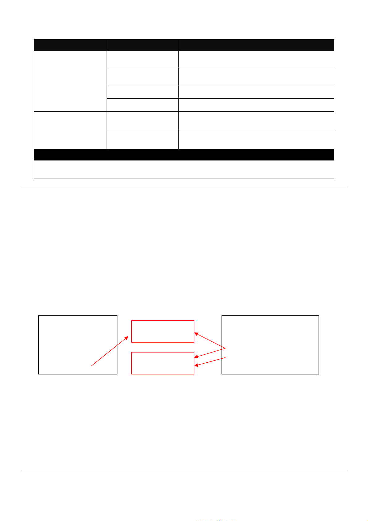
Note: For ISP, the default write protection level is set “home” in configuration file on the ground of
safety, which means the following functions are unable to be overwritten when executing configure
restoration.
1. DDNS
2. Network Setup (LAN-IP, DHCP Server, DHCP Reserved)
3. WiFi (Wireless Setup, Wireless Security)
4. Application (DMZ, Port Forwarding)
5. Security (Firewall, Packet Filter, URL Filter, VPN Pass-Through, UPnP, DDoS)
6. Administration (User Privilege) - Yet if the write protection level is “home”, the user privilege
level “superuser” and “editor” will be deleted except “homeuser”. However, the “homeuser” is
copied from either existing DUT or new configure file. It depends on the write protection level.
Auumed that we have a setting of existing User Previlidge in DUT and a configure file ready to be
loaded.
Here is the treatment of User Privilege of configure restoration:
A. Save the existing homeuser configuration in DUT
B. Reset the DUT back to default setting.
C. Check the write protection level. If the write protection level is “home”, it loads DUT’s homeuser
To overwrite all of configuration, please change the write protection level “home” into “editor”.In
terms of User Previlidge. If the write protection level is “editor”, it loads the homeuser of new
homeuser configure file into DUT
Existing DUT User
Previlidge Accounts:
1. Superuser
2. Editor
3. Homeuser
configure back into DUT.
[A.B.C.D] Enter the IP/IPv6 address of your TFTP
server.
[file name] Enter the configuration file name that you
want to restore.
Write Protection
Level “home”
Write Protection
Level “edito
”
New Configure file of User
Previlidge Accounts::
1. Superuser
2. Homeuser
14

2. Backup configuration file to FTP or TFTP server.
Command Parameter Description
Gateway# copy-cfg
to ftp [A.B.C.D] [file
name] [running |
default | startup ]
[user_name]
[password]
Gateway# copy-cfg
to tftp [A.B.C.D]
[file_name] [running
| default | startup ]
Example
Gateway# copy-cfg to ftp 192.168.1.198 HS_0600_file.conf running misadmin1 abcxyz
Gateway# copy-cfg to tftp 192.168.1.198 HS_0600_file.conf startup
3. Restore the Gateway back to default settings.
Command / Example
Gateway# copy-cfg from default
Gateway# reload
4. Restore the Gateway back to default settings but keep IP configurations.
Command / Example
Gateway# copy-cfg from default keep-ip
Gateway# reload
[A.B.C.D] Enter the IP address of your FTP server.
[file name] Enter the configuration file name that you want to
backup.
[running | default
| startup ]
[user_name] Enter the username for FTP server login.
[password] Enter the password for FTP server login.
[A.B.C.D] Enter the IP address of your TFTP server.
[file name] Enter the configuration file name that you want to
[running | default
| startup ]
Specify backup config to be running, default or
startup
backup.
Specify backup config to be running, default or
startup
2.4.2 Firmware Command
To upgrade firmware via TFTP or FTP server.
Command Parameter Description
Gateway# firmware
upgrade ftp
[A.B.C.D]
[file_name]
[Image-1| Image-2]
[user_name]
[password]
Gateway# firmware
upgrade tftp
[A.B.C.D]
[file_name]
[A.B.C.D] Enter the IP address of your FTP server.
[file name] Enter the firmware file name that you want to
upgrade.
[Image-1| Image2]
[user_name] Enter the username for FTP server login.
[password] Enter the password for FTP server login.
[A.B.C.D] Enter the IP address of your TFTP server.
[file_name] Enter the firmware file name that you want to
Choose image-1 or image-2 for the firmware to
be upgraded to.
upgrade.
15

[Image-1| Image-2] [Image-1| Image-
2]
Example
Gateway# firmware upgrade ftp 192.168.1.198 HS_0600_file.bin edgegateway10 abcxyz
Gateway# firmware upgrade tftp 192.168.1.198 HS_0600_file.bin
Choose image-1 or image-2 for the firmware to
be upgraded to.
2.4.3 Ping Command
Ping is used to test the connectivity of end devices and also can be used to self test the network
interface card. Enter the ping command in User mode. In this command, you can add an optional
packet size value and an optional value for the number of times that packets are sent and received.
Command Parameter Description
Gateway> ping
[A.B.C.D ] [-s size
(1-65500)bytes] [-r
timeout (1-99) secs]
[-t timeout (1-
99)secs]
Example
Gateway> ping 8.8.8.8
Gateway> ping 8.8.8.8 –s 128 –t 10
[A.B.C.D] Enter the IP address that you would like to ping.
[-s size (1-
65500)bytes]
[-r repeat (1-99)
times]
[-t timeout (1-99)
secs]
Enter the packet size that would be sent. The
allowable packet size is from 1 to 65500 bytes.
(optional)
Enter the repeat value that how many times
should be pinged.
Enter the timeout value when the specified IP
address is not reachable. (optional)
2.4.4 Reload Command
1. To restart the Gateway.
Command / Example
Gateway# reload
2. To specify the image for the next restart before restarting.
Command / Example
Gateway# reload Image-2
OK!
Gateway# reload
2.4.5 Traceroute Command
Command Parameter Description
Gateway >
traceroute [A.B.C.D
| URL] [-h 1-100]
hops [-t 1-99] secs
[A.B.C.D | URL] Enter the IP address that you would like to ping.
[-h 1-100] hops Specify max hops between the local host and the
remote host
[-t 1-99] secs Specify timeout time in second
Example
Gateway > traceroute 8.8.8.8
Gateway> traceroute 8.8.8.8 –h 30
16

2.4.6 Write Command
To save running configurations to startup configurations, enter the write command. All unsaved
configurations will be lost when you restart the Gateway.
Command / Example
Gateway# write
Save Config Succeeded!
2.4.7 Configure Command
The only place where you can enter Global Configuration mode is in Privileged mode. You can
type in “configure” or “config” for short to enter Global Configuration mode. The display prompt will
change from “Gateway#” to “Gateway(config)#” once you successfully enter Global Configuration
mode.
Command / Example
Gateway#config
Gateway(config)#
Gateway#configure
Gateway(config)#
2.4.8 Show Command
The “show” command is very important for network administrators to get information about the
device, receive outputs to verify a command’s configurations or troubleshoot a network
configuration error. It can be used in Privileged or Configuration mode. The following describes
different uses of “show” command.
1. Display system information
Enter “show system-info” command in Privileged or Configuration mode, and then the following
information will appear.
Company Name: Display a company name for this Gateway. Use “system-info company-name
[company-name]” command to edit this field.
System Object ID: Display the predefined System OID.
System Contact: Display contact information for this Gateway. Use “system-info system-contact
[sys-contact]” command to edit this field.
System Name: Display a descriptive system name for this Gateway. Use “system-info system-
name [sys-name]” command to edit this field.
System Location: Display a brief location description for this Gateway. Use “system-info system-
location [sys-location]” command to edit this field.
Model Name: Display the product’s model name.
Host Name: Display the product’s host name.
17

DHCP Vendor ID: Enter the Vendor ID used for DHCP relay agent function.
Firmware Version: Display the firmware version used in this device.
Current Boot Image: The image that is currently using.
Configured Boot Image: The image you want to use after reboot.
Image-1 Version: Display the firmware version 1 (image-1) used in this device.
Image-2 Version: Display the firmware version 2 (image-2) used in this device.
M/B Version: Display the main board version.
Serial Number: Display the serial number of this Gateway.
Up Time: Display the up time since last restarting.
Local Time: Display local time.
2. Display or verify currently-configured settings
Refer to the following sub-sections. “Interface command”, “IP command”, “User command”, “VLAN
command” sections, etc.
3. Display interface information or statistics
Refer to “Show interface statistics command” and “Show sfp information command” sections.
4. Show default, running and startup configurations
Refer to “show default-setting copmmand”, “show running-config command” and “show start-upconfig command” sections.
2.5 Configuration Mode
When you enter “configure” or “config” and press “Enter” in Privileged mode, you will be directed to
Global Configuration mode where you can set up advanced switching functions, such as QoS,
VLAN and storm control security globally. All commands entered will apply to running-configuration
and the device’s operation. From this level, you can also enter different sub-configuration modes
to set up specific configurations for VLAN, QoS, security or interfaces.
Command Description
applications
exit
help
history
interface
ip
management
no
ntp
qos
Application global configuration commands.
Exit the configuration mode.
Display a list of available commands in Configuration mode.
Show commands that have been used.
Select a single interface or a range of interfaces.
Set up the IPv4 address and enable DHCP mode & IGMP snooping.
Set up console/telnet/web/SSH access control and timeout value.
Disable a command or set it back to its default setting.
Set up required configurations for Network Time Protocol.
Set up the priority of packets within the Managed Switch.
18

security
show
snmp-server
system-info
syslog
user
vlan
Security global configuration commands.
Show a list of commands or show the current setting of each listed command.
SNMP server configuration commands.
Set up acceptable frame size and address learning, etc.
Set up required configurations for Syslog server.
Create a new user account.
Set up VLAN mode and VLAN configuration.
2.5.1 Entering Interface Numbers
In the Global Configuration mode, you can configure a command that only applies to interfaces
specified. For example, you can set up each interface’s VLAN assignment, speeds, or duplex
modes. To configure, you must first enter the interface number. There are four ways to enter your
interface numbers to signify the combination of different interfaces that apply a command or
commands.
Commands Description
Gateway(config)# interface 1
Gateway(config-if-1)#
Gateway(config)# interface 1,3,5
Gateway(config-if-1,3,5)#
Gateway(config)# interface 1-3
Gateway(config-if-1-3)#
Gateway(config)# interface 1,3-5
Gateway(config-if-1,3-5)#
Enter a single interface. Only interface 1 will
apply commands entered.
Enter three discontinuous interfaces,
separated by commas. Interface 1, 3, 5 will
apply commands entered.
Enter three continuous interfaces. Use a
hyphen to signify a range of interface
numbers. In this example, interface 1, 2, and
3 will apply commands entered.
Enter a single interface number together with
a range of interface numbers. Use both
comma and hypen to signify the combination
of different interface numbers. In this
example, interface 1, 3, 4, 5 will apply
commands entered.
2.5.2 No Command
Almost every command that you enter in Configuration mode can be negated using “no” command
followed by the original or similar command. The purpose of “no” command is to disable a function,
remove a command, or set the setting back to the default value. In each sub-section below, the
use of no command to fulfill different purposes will be introduced.
2.5.3 Show Command
The “show” command is very important for network administrators to get information about the
device, receive outputs to verify a command’s configurations or troubleshoot a network
configuration error. It can be used in Privileged or Configuration mode. The following describes
different uses of “show” command.
1. Display system information
Enter “show system-info” command in Privileged or Configuration mode, and then the following
information will appear.
19

Company Name: Display a company name for this Gateway. Use “system-info company-name
[company-name]” command to edit this field.
System Object ID: Display the predefined System OID.
System Contact: Display contact information for this Gateway. Use “system-info system-contact
[sys-contact]” command to edit this field.
System Name: Display a descriptive system name for this Gateway. Use “system-info system-
name [sys-name]” command to edit this field.
System Location: Display a brief location description for this Gateway. Use “system-info system-
location [sys-location]” command to edit this field.
Model Name: Display the product’s model name.
Host Name: Display the product’s host name.
DHCP Vendor ID: Enter the Vendor ID used for DHCP relay agent function.
Firmware Version: Display the firmware version used in this device.
M/B Version: Display the main board version.
Serial Number: Display the serial number of this Gateway.
Up Time: Display the up time since last restarting.
Local Time: Display local time.
2. Display or verify currently-configured settings
Refer to the following sub-sections. “Interface command”, “IP command”, “User command”, “VLAN
command” sections, etc.
3. Display interface information or statistics
Refer to “Show interface statistics command” and “Show sfp information command” sections.
4. Show default, running and startup configurations
Refer to “show default-setting copmmand”, “show running-config command” and “show start-upconfig command” sections.
2.5.4 Applications Command
1. Set up DMZ function.
Command Parameter Description
Gateway(config)# applications
dmz
Enable DMZ function. DMZ stands for
“Demilitarized Zone”. It is an IP address
on the private network of the Residential
Gateway. But it is exposed to the Internet
20

for special-purpose services. So a host on
the private network can be assigned the
IP address of the DMZ to provide services
to the hosts on the Internet. The network
administrator should be cautious of
adopting DMZ. If a host is on DMZ, it is
not protected by the firewall. And the
Residential Gateway will open all ports to
expose DMZ to the Internet. This may
expose the local network to a variety of
security risk.
Gateway(config)# applications
destination-ip [A.B.C.D]
Gateway(config)# applications
source-ip [A.B.C.D] [1-254]
Gateway(config)# applications
source-ip any
No Command
Gateway(config)# no
applications dmz
Show Command
Gateway(config)# show
applications dmz
2. Set up Port Forwarding function.
Command Parameter Description
Gateway(config)# applications
port-forwarding
Gateway(config)# applications
port-forwarding apply
Gateway(config-port-forwardingNo.)# active
Gateway(config-port-forwardingNo.)# description [description]
Gateway(config-port-forwarding- [A.B.C.D] Specify the IP address of the server on
[A.B.C.D] Specify the IP address of the host on the
DMZ.
[A.B.C.D]
[1-254]
Allow any IP address to expose the DMZ
Disable DMZ function.
Shows the current status of DMZ.
Enable Port Forwarding function. A host
Apply all the configured port forwarding
Enable the port forwarding rule.
[description] Specify any remark on the rule up to 20
Specify an IP address range in the text
boxes so the DMZ will be exposed to the
IP address in the specified IP address
range only.
to any IP address on the Internet.
on the private network of the Residential
Gateway is invisible from the Internet for it
is protected by the firewall. Therefore,
when a server is on the private network,
its service will be inaccessible from the
Internet. To open the service to hosts on
the Internet, the network administrator
may adopt Port Forwarding feature. Port
Forwarding allows an IP address on the
private network to be accessed from an IP
address on the public network. It will
redirect packets from the public network
to a specified private IP address if the
packets meet the pre-condition of a port
forwarding rule.
settings made.
characters.
21

No.)# client-ip [A.B.C.D] the private network.
Gateway(config-port-forwarding-
No.)# local-port [1-65535]
Gateway(config-port-forwardingNo.)# public-port [1-65535]
Gateway(config-port-forwardingNo.)# protocol [both|tcp|udp]
No Command
Gateway(config)# no
applications port-forwarding
Gateway(config)# no
applications port-forwarding [110]
Gateway(config-port-forwardingNo.)# no active
Gateway(config-port-forwardingNo.)# no description
Gateway(config-port-forwardingNo.)# no client-ip
Gateway(config-port-forwardingNo.)# no local-port
Gateway(config-port-forwardingNo.)# no public-port
Gateway(config-port-forwardingNo.)# no protocol
Show Command
Gateway(config)# show
applications port-forwarding
Gateway(config-port-forwardingNo.)# show
[1-65535] Specify the port number which the
packets are destined to (1~65535).
[1-65535] Specify the port number which the
packets from the Internet are destined to
(1~65535).
[both|tcp|udp] Choose TCP, UDP or Both as your
desired protocol.
Disable Port Forwarding function.
[1-10] Delete the specified port forwarding rule.
Disable the port forwarding rule.
Clear the remark on the rule.
Clear the IP address of the server on the
private network.
Return local port to default value 1.
Return public port to default value 1.
Return protocol to default value “Both”.
Shows the status of port forwarding.
Shows the current status of the rule.
2.5.5 Interface Command
Use “interface” command to set up configurations of several discontinuous ports or a range of
ports.
1. Entering interface numbers.
Command Parameter Description
Gateway(config)# interface lan
[port_list]
Gateway(config)# interface wan
[port_list]
Gateway(config)# interface
wlan1
Gateway(config)# interface
wlan2
[port_list] Enter several lan port numbers separated
by commas or a range of port numbers.
For example: 1,3 or 2-4
[port_list] Enter several wan port numbers
separated by commas or a range of port
numbers.
Enter WiFi 5G interface.
Enter WiFi 2.4G interface.
22

Note : You need to enter interface numbers first before issuing below 2-15 commands.
2. Enable port auto-negotiation.
Command Parameter Description
Gateway(config-net-PORTPORT)# auto-negotiation
No command
Gateway(config-net-PORTPORT)# no auto-negotiation
3. Enable port auto-negotiation.
Command Parameter Description
Gateway(config-net-PORTPORT)# combo-mode
[copper|fiber]
No command
Gateway(config-net-PORTPORT)# no combo-mode
4. Set up port duplex mode.
Command Parameter Description
Gateway(config-net-PORTPORT)# duplex [full]
Set the selected interfaces’ to auto-
negotiation. When auto-negotiation is
enabled, speed configuration will be
ignored.
Set auto-negotiation setting to the default
setting.
[copper|fiber] Specify combo port on copper or fiber
port.
Disable combo mode.
[full] Configure port duplex to full.
No command
Gateway(config-net-PORTPORT)# no duplex
5. Enable flow control operation.
Command Parameter Description
Gateway(config-net-PORTPORT)# flowcontrol
No command
Gateway(config-net-PORTPORT)# no flowcontrol
6. Operation mode selection.
Configure port duplex to half.
Note1 : Only copper ports can be
configured as half duplex.
Note2 : Auto-negotiation needs to be
disabled before configuring duplex
mode.
Enable flow control on port(s).
Disable flow control on port(s).
23

Command Parameter Description
Gateway(config-net-PORTPORT)# operation-mode nat
Gateway(config-net-PORTPORT)# operation-mode bridge
No command
Gateway(config-net-PORTPORT)# no operation-mode
7. Shutdown Interface.
Command Parameter Description
Gateway(config-net-PORTPORT)# shutdown
No command
Gateway(config-net-PORTPORT)# no shutdown
8. Set up port speed.
Command Parameter Description
Gateway(config-net-PORTPORT)# speed [1000|100|10]
No command
Gateway(config-net-PORTPORT)# no speed
9. Set up VLAN parameters per port.
Command Parameter Description
Gateway(config-net-PORTPORT)# vlan dot1q-vlan accessvlan [1-4094]
Gateway(config-net-PORTPORT)# vlan dot1q-vlan trunkvlan [1-4094]
Enable NAT mode. When the Residential
Gateway is in this mode, all devices
connected to the Residential Gateway
from its LAN ports and WLAN are in the
private network.
Enable Bridge mode. When the
Residential Gateway is in this mode, all
devices connected to the Residential
Gateway from its LAN ports or WLAN are
in the public network.
Return to NAT mode.
Disable interface.
Enable interface.
[1000|100|10] Set port speed as 1000Mbps, 100Mbps or
10Mbps.
Note1 : Speed can only be configured
when auto-negotiation is disabled.
Note2: Fiber ports can not be
configured as 10Mbps.
Undo port speed setting.
[1-4094] Configure port PVID.
[1-4094] Configure port VID.
24

Gateway(config-net-PORTPORT)# vlan dot1q-vlan mode
access
Gateway(config-net-PORTPORT)# vlan dot1q-vlan mode
trunk
Gateway(config-net-PORTPORT)# vlan dot1q-vlan mode
trunk native
No command
Gateway(config-net-PORTPORT)# vlan dot1q-vlan accessvlan
Gateway(config-net-PORTPORT)# vlan dot1q-vlan trunkvlan
Gateway(config-net-PORTPORT)# vlan dot1q-vlan mode
Gateway(config-net-PORTPORT)# no vlan dot1q-vlan
mode trunk native
Show command
Gateway(config-net-PORTPORT)# show interface
Gateway(config-net-PORTPORT)# show dot1q-vlan tagvlan
10. Set up WiFi advanced settings. (For WiFi Model Only)
For Bandwidth 5G:
Command Parameter Description
Gateway(config)# interface
wlan1
Gateway(config)# interface
wlan1 apply
Gateway(config-wlan1)#
aggregation
Gateway(config-wlan1)#
beacon-interval [20-1024]
Gateway(config-wlan1)#
channel [channel_number]
Gateway(config-wlan1)#
channel width [20|40|80]
Access WiFi bandwidth 5G advanced settings.
Apply all change made on WiFi bandwidth 5G
Enable Aggregation function.
[20-1024] Specify the Beacon Interval threshold in ms
[channel_number] Specify the channel number from the list shown
[20|40|80] Specify the channel width in MHz.
Configure port as dot-1q access port.
Configure port as dot-1q trunk port. This
is for LAN and WAN only.
Configure port as dot-1q trunk native port.
This is for LAN and WAN only.
Undo configure port PVID.
Undo configure port VID.
Undo VLAN mode configuration.
Undo VLAN trunk native mode
configuration.
Show the current status of each port.
Show IEEE802.1q tag VLAN table.
advanced settings.
ranging between 20-1024. The default value is
100.
below:
Channel Number: auto, 36, 40, 44, 48, 52,
56, 60, 64, 100, 104, 108, 112, 116, 120, 124,
128.
25

Gateway(config-wlan1)#
fragment-threshold [2562346]
Gateway(config-wlan1)#
iapp
Gateway(config-wlan1)#
ldpc
Gateway(config-wlan1)#
multicast-rate [auto|1-44]
Gateway(config-wlan1)#
multicast-to-unicast
Gateway(config-wlan1)#
protection
Gateway(config-wlan1)# rfoutput-power
[100|70|50|35|15]
Gateway(config-wlan1)#
rts-threshold [0-2347]
Gateway(config-wlan1)#
short-gi
Gateway(config-wlan1)#
stbc
Gateway(config-wlan1)#
tdls channel-switchprohibited
Gateway(config-wlan1)#
tdls prohibited
Gateway(config-wlan1)# txbreamforming
Gateway(config-wlan1)#
wlan-partition
[256-2346] Specify the fragment threshold ranging
between 256-2346. The default value is 2346.
Enable IAPP function.
Enable LDPC function.
[auto|1-44] Specify the number corresponding its data rate
respectively as below:
1:6m 2:9m 3:12m 4:18m
5:24m 6:36m 7:48m 8:54m
9:msc0 10:msc1 11:msc2 12:msc3
13:msc4 14:msc5 15:msc6 16:msc7
17:msc8 18:msc9 19:msc10 20:msc11
21:msc12 22:msc13 23:msc14 24:msc15
25:nss1msc0
29:nss1msc4
33:nss1msc8
37:nss2msc2
41:nss2msc6
Enable Multicast to Unicast function.
Enable Protection function.
[100|70|50|35|15] Specify the percentage of RF Output Power
level, 100%, 70%, 50%, 35% and 15% are
available.
[0-2347] Specify the RTS threshold ranging between 0-
2347. The default value is 2347.
Enable Short GI function.
Enable STBC function.
Enable TDLS Channel Switch Prohibited
function.
Enable TDLS Prohibited function.
Enable Tx Beamforming function.
Enable WLAN Partition function.
26:nss1msc1
30:nss1msc5
34:nss1msc9
38:nss2msc3
42:nss2msc7
27:nss1msc2
31:nss1msc6
35:nss2msc0
39:nss2msc4
43:nss2msc8
28:nss1msc3
32:nss1msc7
36:nss2msc1
40:nss2msc5
44:nss2msc9
26

Gateway(config-wlan1)#
wps
No Command
Enable WPS function.
Gateway(config-wlan1)# no
aggregation
Gateway(config-wlan1)# no
beacon-interval
Gateway(config-wlan1)# no
channel
Gateway(config-wlan1)# no
channel width
Gateway(config-wlan1)# no
fragment-threshold
Gateway(config-wlan1)# no
iapp
Gateway(config-wlan1)# no
ldpc
Gateway(config-wlan1)# no
multicast-rate
Gateway(config-wlan1)# no
multicast-to-unicast
Gateway(config-wlan1)# no
protection
Gateway(config-wlan1)# no
rf-output-power
Gateway(config-wlan1)# no
rts-threshold
Gateway(config-wlan1)# no
short-gi
Gateway(config-wlan1)# no
stbc
Gateway(config-wlan1)# no
tdls channel-switchprohibited
Gateway(config-wlan1)# no
tdls prohibited
Gateway(config-wlan1)# no
tx-breamforming
Gateway(config-wlan1)# no
wlan-partition
Gateway(config-wlan1)#
wps
Show Command
Gateway(config)# show
interface wlan1
For Bandwidth 2.4G:
Command Parameter Description
Disable Aggregation function.
Return Beacon Interval to default value.
Return channel number to default value.
Return channel width to default value.
Return fragment threshold to default value.
Disable IAPP function.
Disble LDPC function.
Return multicast rate to default value
Disable Multicast to Unicast function.
Disable Protection function.
Return RF output power to default value.
Return RTS threshold to default value.
Disable Short GI function.
Disable STBC function.
Disable TDLS Channel Switch Prohibited
function.
Disable TDLS Prohibited function.
Disable Tx-Beamforming function.
Disable WLAN Partition function.
Disable WPS function.
Shows the current advanced status of WiFi 5G.
27

Gateway(config)# interface
wlan2
Gateway(config)# interface
wlan2 apply
Gateway(config-wlan2)#
aggregation
Gateway(config-wlan2)#
beacon-interval [20-1024]
Gateway(config-wlan2)#
control-sideband
[upper|lower]
Gateway(config-wlan2)#
channel [channel_number]
Gateway(config-wlan2)#
coexist
Gateway(config-wlan2)#
channel width [20|40|80]
Gateway(config-wlan2)#
fragment-threshold [2562346]
Gateway(config-wlan2)#
iapp
Gateway(config-wlan2)#
ldpc
Gateway(config-wlan2)#
multicast-rate [auto|1-44]
Access WiFi bandwidth 2.4G advanced
settings.
Apply all change made on WiFi bandwidth
2.4G advanced settings.
Enable Aggregation function.
[20-1024] Specify the Beacon Interval threshold in ms
ranging between 20-1024. The default value is
100.
[upper|lower] The extra bandwidth will be available when the
channel bandwidth is 40MHz. If you select
Upper, the extra bandwidth will be extended in
the upper sideband. (This field is only available
when the network mode is 2.4 GHz (N), 2.4
GHz (G+N), or 2.4 GHz (B+G+N).)
[channel_number] Specify the channel number from the list shown
below:
Channel Number: auto, 5-13
Enable Coexist function.
[20|40|80] Specify the channel width in MHz.
[256-2346] Specify the fragment threshold ranging
between 256-2346. The default value is 2346.
Enable IAPP function.
Enable LDPC function.
[auto|1-44] Specify the number corresponding its data rate
respectively as below:
1:6m 2:9m 3:12m 4:18m
5:24m 6:36m 7:48m 8:54m
9:msc0 10:msc1 11:msc2 12:msc3
13:msc4 14:msc5 15:msc6 16:msc7
17:msc8 18:msc9 19:msc10 20:msc11
21:msc12 22:msc13 23:msc14 24:msc15
25:nss1msc0
29:nss1msc4
33:nss1msc8
37:nss2msc2
41:nss2msc6
26:nss1msc1
30:nss1msc5
34:nss1msc9
38:nss2msc3
42:nss2msc7
27:nss1msc2
31:nss1msc6
35:nss2msc0
39:nss2msc4
43:nss2msc8
28:nss1msc3
32:nss1msc7
36:nss2msc1
40:nss2msc5
44:nss2msc9
28

Gateway(config-wlan2)#
multicast-to-unicast
Gateway(config-wlan2)#
preamble-type [long|short]
Gateway(config-wlan2)#
protection
Gateway(config-wlan2)# rfoutput-power
[100|70|50|35|15]
Gateway(config-wlan2)#
rts-threshold [0-2347]
Gateway(config-wlan2)#
short-gi
Gateway(config-wlan2)#
stbc
Gateway(config-wlan2)#
tdls channel-switchprohibited
Gateway(config-wlan2)#
tdls prohibited
Gateway(config-wlan2)# txbreamforming
Gateway(config-wlan2)#
wlan-partition
Gateway(config-wlan2)#
wps
No Command
Enable Multicast to Unicast function.
[long|short] Specify Preamble Type, either Long Preamble
Enable Protection function.
[100|70|50|35|15] Specify the percentage of RF Output Power
[0-2347] Specify the RTS threshold ranging between 0-
Enable Short GI function.
Enable STBC function.
Enable TDLS Channel Switch Prohibited
Enable TDLS Prohibited function.
Enable Tx Beamforming function.
Enable WLAN Partition function.
Enable WPS function.
or Short Preamble.
level, 100%, 70%, 50%, 35% and 15% are
available.
2347. The default value is 2347.
function.
Gateway(config-wlan2)# no
aggregation
Gateway(config-wlan2)# no
beacon-interval
Gateway(config-wlan2)#
control-sideband
Gateway(config-wlan2)# no
channel
Gateway(config-wlan2)# no
coexist
Gateway(config-wlan2)# no
channel width
Gateway(config-wlan2)# no
fragment-threshold
Gateway(config-wlan2)# no
iapp
Gateway(config-wlan2)# no
ldpc
Gateway(config-wlan2)# no
multicast-rate
Disable Aggregation function.
Return Beacon Interval to default value.
Return sideband to default value.
Return channel number to default value.
Disable Coexist function.
Return channel width to default value.
Return fragment threshold to default value.
Disable IAPP function.
Disble LDPC function.
Return multicast rate to default value
29

Gateway(config-wlan2)# no
multicast-to-unicast
Gateway(config-wlan2)# no
preamble-type
Gateway(config-wlan2)# no
protection
Gateway(config-wlan2)# no
rf-output-power
Gateway(config-wlan2)# no
rts-threshold
Gateway(config-wlan2)# no
short-gi
Gateway(config-wlan2)# no
stbc
Gateway(config-wlan2)# no
tdls channel-switchprohibited
Gateway(config-wlan2)# no
tdls prohibited
Gateway(config-wlan2)# no
tx-breamforming
Gateway(config-wlan2)# no
wlan-partition
Gateway(config-wlan2)# no
wps
Show Command
Gateway(config)# show
interface wlan2
11. Set up WiFi basic & security settings. (For WiFi Model Only)
For Bandwidth 5G:
Command Parameter Description
Gateway(config)# interface
wlan1
Gateway(config)# interface
wlan1ssid [1-4]
Gateway(config-wlan1-ssidNo.)# active
Gateway(config-wlan1-ssidNo.)# broadcast
Gateway(config-wlan1-ssidNo.)# datarate [auto|1-44]
Disable Multicast to Unicast function.
Return Preamble Type to default value.
Disable Protection function.
Return RF output power to default value.
Return RTS threshold to default value.
Disable Short GI function.
Disable STBC function.
Disable TDLS Channel Switch Prohibited
function.
Disable TDLS Prohibited function.
Disable Tx-Beamforming function.
Disable WLAN Partition function.
Disable WPS function.
Shows the current advanced status of WiFi
2.4G.
Access WiFi bandwidth 5G settings.
[1-4] Specify the SSID you want to configure.
Enable the WiFi service set.
Have the SSID disclose in public.
[auto|1-44] Specify the number corresponding its data rate
respectively as below:
1:6m 2:9m 3:12m 4:18m
5:24m 6:36m 7:48m 8:54m
9:msc0 10:msc1 11:msc2 12:msc3
13:msc4 14:msc5 15:msc6 16:msc7
17:msc8 18:msc9 19:msc10 20:msc11
30