

ConnectGear GS-1124 User Manual
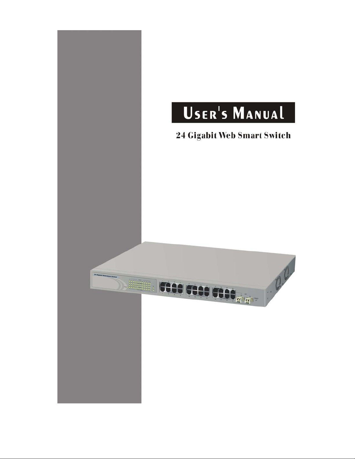


24 Gigabit Web Smart Switch
User's Manual
Release 1.03

Table of Contents
CAUTION--------------------------------------------------------------------------------------------------------- VI
ELECTRONIC EMISSION NOTICES---------------------------------------------------------------------------- VI
CHAPTER 1. INTRODUCTION ------------------------------------------------------------------------------ 2
1-1.
OVERVIEW OF 24 GIGABIT WEB SMART SWITCH----------------------------------------------------- 2
1-2. CHECKLIST ------------------------------------------------------------------------------------------------- 3
1-3.
FEATURES -------------------------------------------------------------------------------------------------- 3
1-4. VIEW OF 24 GIGABIT WEB SMART SWITCH ----------------------------------------------------------- 5
1-4-1. User Interfaces on the Front Panel (Button, LEDs and Plugs)------------------------- 5
1-4-2. User Interfaces on the Rear Panel------------------------------------------------------------ 6
1-5.
VIEW OF THE OPTIONAL MODULES --------------------------------------------------------------------- 7
CHAPTER 2. INSTALLATION-------------------------------------------------------------------------------- 8
2-1.
STAR TING 24 GIGABIT WEB SMART SWITCH UP ----------------------------------------------------- 8
2-1-1. Hardware and Cable Installation -------------------------------------------------------------- 8
2-1-2. Cabling Requirements --------------------------------------------------------------------------- 9
2-1-2-1. Cabling Requirements for TP Ports -------------------------------------------------- 10
2-1-2-2. Cabling Requirements for 1000SX/LX SFP Module------------------------------ 10
2-1-2-3. Switch Cascading in Topology----------------------------------------------------------11
2-1-3. Configuring the Management Agent of 24 Gigabit Web Smart Switch ------------- 14
2-1-3-1. Configuring Management Agent of 24 Gigabit Web Smart Switch through
Ethernet Port ------------------------------------------------------------------------------------------ 15
2-1-4. IP Address Assignment ------------------------------------------------------------------------ 16
2-2.
TYPICAL APPLICATIONS--------------------------------------------------------------------------------- 21
CHAPTER 3. BASIC CONCEPT AND MANAGEMENT--------------------------------------------- 23
3-1.
WHAT’S THE ETHERNET -------------------------------------------------------------------------------- 23
3-2. MEDIA ACCESS CONTROL (MAC) -------------------------------------------------------------------- 26
3-3.
FLOW CONTROL ----------------------------------------------------------------------------------------- 32
3-4. HOW DOES A SWITCH WORK?-------------------------------------------------------------------------- 35
3-5. VIRTUAL LAN -------------------------------------------------------------------------------------------- 39
3-6.
LINK AGGREGATION ------------------------------------------------------------------------------------- 45
CHAPTER 4. OPERATION OF WEB-BASED MANAGEMENT ---------------------------------- 47
WEB MANAGEMENT HOME OVERVIEW--------------------------------------------------------------- 48
4-1.
4-2.
CONFIGURATION----------------------------------------------------------------------------------------- 50
4-2-1. System Configuration -------------------------------------------------------------------------- 51
4-2-2. Ports Configuration ----------------------------------------------------------------------------- 54
4-2-3. VLAN Mode Configuration -------------------------------------------------------------------- 55
4-2-4. VLAN Group Configuration ------------------------------------------------------------------- 58
4-2-5. PVID Configuration ----------------------------------------------------------------------------- 61
4-2-6. Aggregation Configuration -------------------------------------------------------------------- 63
4-2-7. Mirror Configuration ---------------------------------------------------------------------------- 64
4-2-8. Quality of Service Configuration------------------------------------------------------------- 65
4-2-9. Bandwidth Management----------------------------------------------------------------------- 74
4-2-10. Trap Event Configuration -------------------------------------------------------------------- 76
4-2-11. Max. Packet Length--------------------------------------------------------------------------- 77
ii

MONITORING --------------------------------------------------------------------------------------------- 78
4-3.
4-3-1. Statistics Overview------------------------------------------------------------------------------ 78
4-3-2. Detailed Statistics ------------------------------------------------------------------------------- 79
4-4.
MAINTENANCE ------------------------------------------------------------------------------------------- 82
4-4-1. Status ---------------------------------------------------------------------------------------------- 82
4-4-1-1.Switch Status ------------------------------------------------------------------------------- 83
4-4-1-2. TP / Fiber Ports Status------------------------------------------------------------------- 85
4-4-1-3. Aggregation -------------------------------------------------------------------------------- 87
4-4-1-4. VLAN----------------------------------------------------------------------------------------- 88
4-4-1-5. Mirror----------------------------------------------------------------------------------------- 90
4-4-1-6. Trap Event---------------------------------------------------------------------------------- 91
4-4-1-7. Maximum Packet Length---------------------------------------------------------------- 92
4-4-2. Warm Restart ------------------------------------------------------------------------------------ 93
4-4-3. Factory Default ---------------------------------------------------------------------------------- 94
4-4-4. Logout --------------------------------------------------------------------------------------------- 95
CHAPTER 5. MAINTENANCE ----------------------------------------------------------------------------- 96
5-1.
RESOLVING NO LINK CONDITION --------------------------------------------------------------------- 96
5-2.
Q&A------------------------------------------------------------------------------------------------------- 96
APPENDIX A TECHNICAL SPECIFICATIONS-------------------------------------------------------- 97
APPENDIX B MIB SPECIFICATIONS ------------------------------------------------------------------101
iii

Revision History
Release Date Revision
1.01 12/17/2004 A1
1.03 01/20/2005 A1
1.03 01/26/2005 A1
iv

v

Caution
Circuit devices are sensitive to static electricity, which can damage their delicate
electronics. Dry weather conditions or walking across a carpeted floor may cause you to
acquire a static electrical charge.
To protect your device, always:
• Touch the metal chassis of your computer to ground the static electrical charge before
you pick up the circuit device.
• Pick up the device by holding it on the left and right edges only.
Electronic Emission Notices
Federal Communications Commission (FCC) Statement
This equipment has been tested and found to comply with the limits for a class A
computing device pursuant to Subpart J of part 15 of FCC Rules, which are designed to
provide reasonable protection against such interference when operated in a commercial
environment.
European Community (CE) Electromagnetic Compatibility Directive
This equipment has been tested and found to comply with the protection requirements
of European Emission Standard EN55022/EN60555-2 and the Generic European Immunity
Standard EN50082-1.
EMC:
EN55022(1988)/CISPR-22(1985) class A
EN60555-2(1995) class A
EN60555-3
IEC1000-4-2(1995) 4K V CD, 8KV, AD
IEC1000-4-3(1995) 3V/m
IEC1000-4-4(1995) 1KV – (power line), 0.5KV – (signal line)
vi

About this user’s manual
In this user’s manual, it will not only tell you how to install and connect your
network system but configure and monitor the 24 Gigabit Web Smart Switch
through the built-in console and web by RS-232 serial interface and Ethernet ports
step-by-step. Many explanation in detail of hardware and software functions are
shown as well as the examples of the operation for web-based interface and textbased menu-driven console interface.
Overview of this user’s manual
Chapter 1 “Introduction” describes the features of 24 Gigabit Web
Smart Switch
Chapter 2 “Installation”
Chapter 3 “Operating Concept and Management”
Chapter 4 “Operation of Web-based Management”
Chapter 5 “Operation of Menu-driven Console”
Chapter 6 “Maintenance”
Publication date: January, 2005
Revision A1
1

User Manual
1. Introduction
1-1. Overview of 24 Gigabit Web Smart Switch
24-port Gigabit Web Smart Switch is a standard switch that meets all IEEE
802.3/u/x/z Gigabit, Fast Ethernet specifications. The switch included 22-Port
10/100/1000Mbps TP and 2-Port Gigabit TP/SFP Fiber Web Smart management
Ethernet Switch. The switch can be managed through Ethernet port using Webbased management unit, associated with web-based management, the network
administrator can logon the switch to monitor, configure and control each port’s
activity. In addition, the switch implements the QoS (Quality of Service), VLAN, and
Trunking. It is suitable for office application.
In this switch, Port 23, 24 includes two types of media --- TP and SFP Fiber
(LC, BiDi-SC…); this port supports 10/100/1000Mbps TP or 1000Mbps SFP Fiber
with auto-detected function. 1000Mbps SFP Fiber transceiver is used for highspeed connection expansion.
1000Mbps LC, Multi-Mode, SFP Fiber transceiver
1000Mbps LC, 10km, SFP Fiber transceiver
1000Mbps LC, 30km, SFP Fiber transceiver
1000Mbps LC, 50km, SFP Fiber transceiver
1000Mbps BiDi-SC, 20km, 1550nm SFP Fiber WDM transceiver
1000Mbps BiDi-SC, 20km, 1310nm SFP Fiber WDM transceiver
10/100/1000Mbps TP is a standard Ethernet port that meets all IEEE
802.3/u/x/z Gigabit, Fast Ethernet specifications. 1000Mbps SFP Fiber transceiver
is a Gigabit Ethernet port that fully complies with all IEEE 802.3z and 1000BaseSX/LX standards.
1000Mbps Single Fiber WDM (BiDi) transceiver is designed with an optic
Wavelength Division Multiplexing (WDM) technology that transports bi-directional
full duplex signal over a single fiber simultaneously.
•
Key Features in the Device
QoS:
The
switch offers powerful QoS function. This function supports TOS field of
IP header (equal DSCP low 3 bits) on Layer 3 of network framework and 6
kinds of special network transmission events on Layer 4.
VLAN:
Supports Port-based VLAN, IEEE802.1Q Tag VLAN. And supports 24 active
VLANs and VLAN ID 1~4094.
Port Trunking:
Allows one or more links to be aggregated together to form a Link
Aggregation Group by the static setting.
Publication date: January, 2005
Revision A1
2

User Manual
1-2. Checklist
Before you start installing the switch, verify that the package contains the
following:
A set of 24 Gigabit Web Smart Switch
Modules (optional)
Mounting Accessory (for 19” Rack Shelf)
This User's Manual in CD-ROM
AC Power Cord
Please notify your sales representative immediately if any of the aforementioned
items is missing or damaged.
1-3. Features
The 24 Gigabit Web Smart Switch, a standalone off-the-shelf switch,
provides the comprehensive features listed below for users to perform system
network administration and efficiently and securely serve your network.
•
Hardware
• 22 10/100/1000Mbps Auto-negotiation Gigabit Ethernet TP ports
• 2 10/100/1000Mbps TP or 1000Mbps SFP Fiber dual media auto sense
• 400KB on-chip frame buffer
• Jumbo frame support
• Programmable classifier for QoS (Layer 4/Multimedia)
• 8K MAC address and 4K VLAN support (IEEE802.1Q)
• Per-port shaping, policing, and Broadcast Storm Control
• IEEE802.1Q-in-Q nested VLAN support
• Full-duplex flow control (IEEE802.3x) and half-duplex backpressure
• Extensive front-panel diagnostic LEDs; System: Power, TP Port1-24: LINK/ACT,
10/100/1000Mbps, SFP Port 23,24: SFP(LINK/ACT)
• Management
• Supports concisely the status of port and easily port configuration
• Supports per port traffic monitoring counters
• Supports a snapshot of the system Information when you login
• Supports port mirror function
• Supports the static trunk function
Publication date: January, 2005
Revision A1
3

User Manual
• Supports 802.1Q VLAN
• Supports user management and limits one user to login
• Maximal packet length can be up to 9216 bytes for jumbo frame application
• Supports Broadcasting Suppression to avoid network suspended or crashed
• Supports to send the trap event while monitored events happened
• Supports default configuration which can be restored to overwrite the current
configuration which is working on via Web UI and Reset button of the switch
• Supports on-line plug/unplug SFP modules
• Supports Quality of Service (QoS) for real time applications based on the
information taken from Layer 2 to Layer 4, such as VoIP
• Built-in web-based management instead of using CLI interface, providing a more
convenient GUI for the user
Publication date: January, 2005
Revision A1
4
User Manual
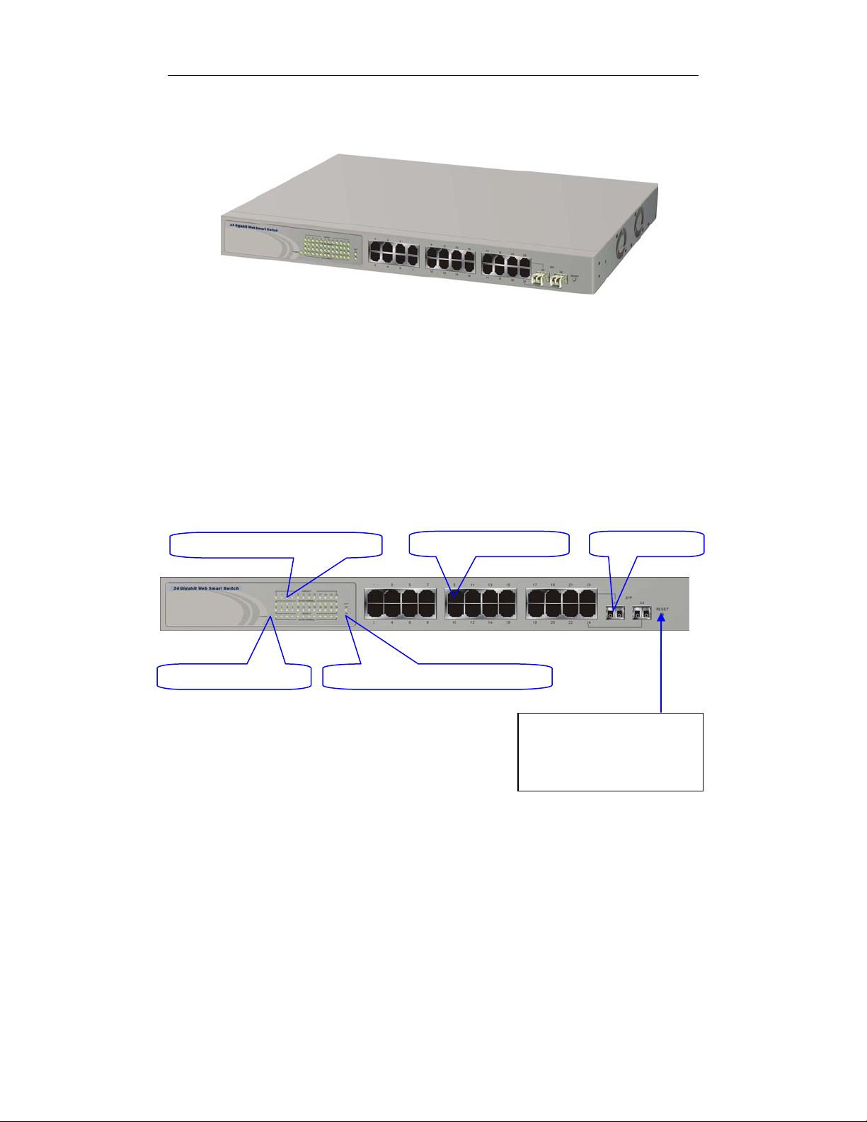
1-4. View of 24 Gigabit Web Smart Switch
Fig. 1-1 Full View of 24 Gigabit Web Smart Switch
1-4-1. User Interfaces on the Front Panel (Button, LEDs and Plugs)
There are 24 TP Gigabit Ethernet ports and 2 SFP fiber ports for optional
removable modules on the front panel of the switch. LED display area, locating on
the left side of the panel, contains a Power LED, which indicates the power status
and 24 ports working status of the switch.
TP Port Status Indication LEDs
Power Indication LED
Fig. 1-2 Front View of 24 Gigabit Web Smart Switch
Gigabit Ethernet Port
Fiber Port Status Indication LEDs
SFP Fiber Port
RESET Button:
RESET button is used to
restore the system default
setting.
Publication date: January, 2005
Revision A1
5
User Manual
• LED Indicators
LED Color Function
System LED
POWER Green Lit when +5V DC power is on and good
10/100/1000Ethernet TP Port 1 to 24 LED
Lit when connection with remote device is good
LINK/ACT Green
10/100/1000Mbps
1000SX/LX Gigabit Fiber Port 23, 24 LED
SFP(LINK/ACT) Green
Green/
Ember
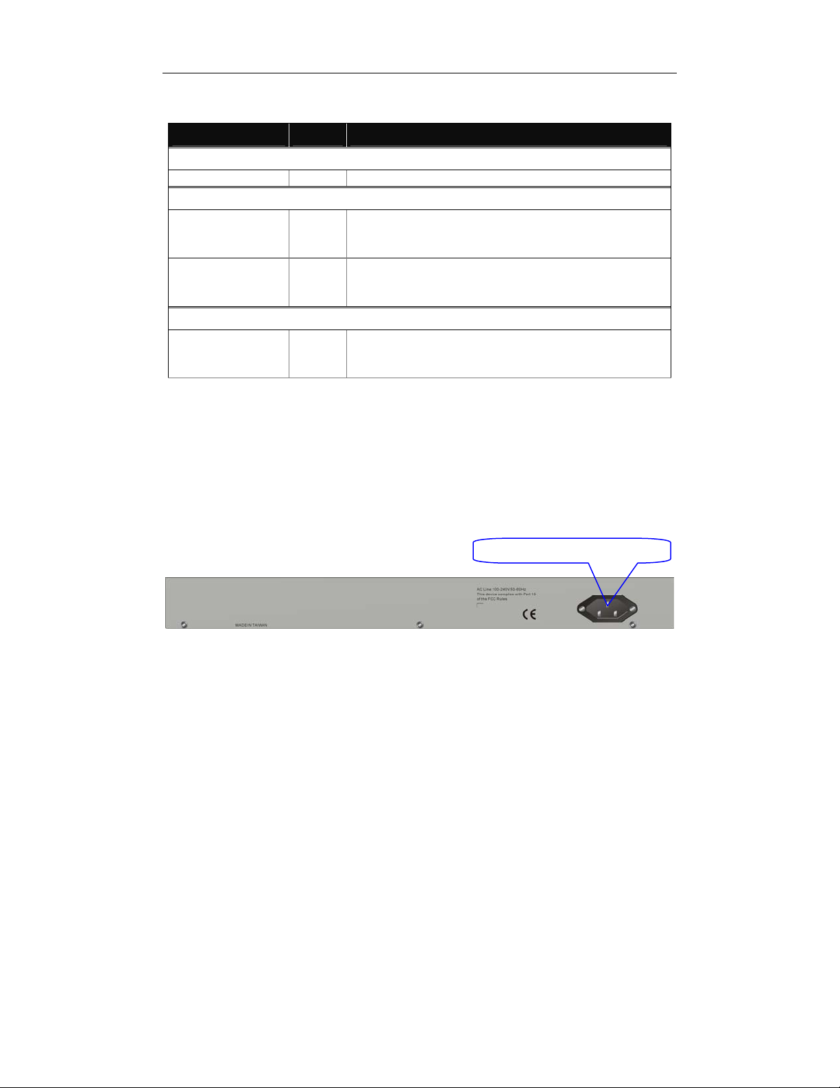
1-4-2. User Interfaces on the Rear Panel
Blinks when any traffic is present
Off when cable connection is not good
Lit green when 1000Mbps speed is active
Lit ember when 100Mbps speed is active
Off when 10Mbps speed is active
Lit when connection with the remote device is good
Blinks when any traffic is present
Off when module connection is not good
Table1-1
AC Line 100-240V 50/60 Hz
Fig. 1-3 Rear View of 24 Gigabit Web Smart Switch
Publication date: January, 2005
Revision A1
6
User Manual
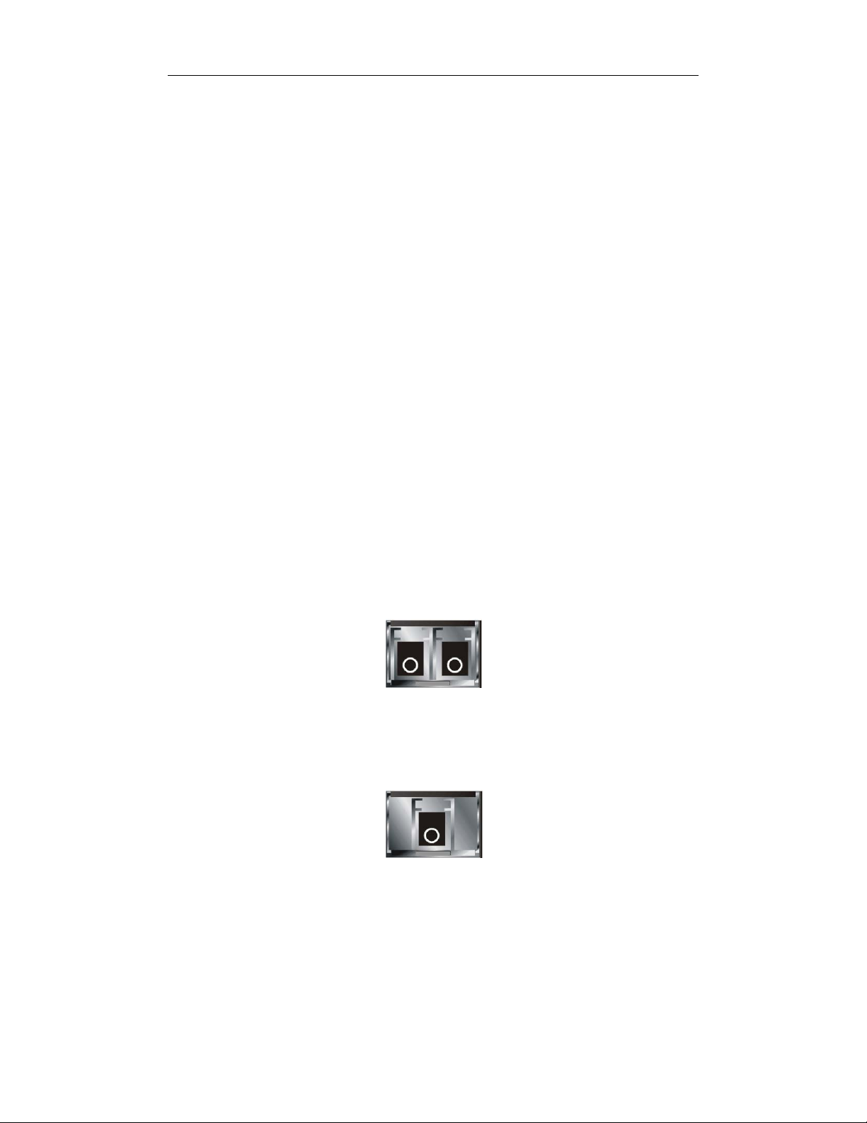
1-5. View of the Optional Modules
In the switch, Port 23~24 includes two types of media --- TP and SFP Fiber
(LC, BiDi-SC…); this port supports 10/100/1000Mbps TP or 1000Mbps SFP Fiber
with auto-detected function. 1000Mbps SFP Fiber transceiver is used for highspeed connection expansion; nine optional SFP types provided for the switch are
listed below:
1000Mbps LC, MM, SFP Fiber transceiver
1000Mbps LC, SM 10km, SFP Fiber transceiver
1000Mbps LC, SM 30km, SFP Fiber transceiver
1000Mbps LC, SM 50km, SFP Fiber transceiver
1000Mbps LC, SM 70km, SFP Fiber transceiver
1000Mbps LC, SM 110km, SFP Fiber transceiver
1000Mbps BiDi SC, type 1, SM 20km, SFP Fiber WDM transceiver
1000Mbps BiDi SC, type 2, SM 20km, SFP Fiber WDM transceiver
1000Mbps LC, SM 10km, SFP Fiber transceiver with DDM
Fig. 1-4 Front View of 1000Base-SX/LX LC, SFP Fiber Transceiver
Fig. 1-5 Front View of 1000Base-LX BiDi SC SFP Fiber Transceiver
Publication date: January, 2005
Revision A1
7
User Manual
r
2. Installation
2-1. Starting 24 Gigabit Web Smart Switch Up
This section will give users a quick start for:
- Hardware and Cable Installation
- Management Station Installation
- Software booting and configuration
2-1-1. Hardware and Cable Installation
At the beginning, please do first:
⇒ Wear a grounding device to avoid the damage from electrostatic discharge
⇒ Be sure that power switch is OFF before you insert the power cord to power
source
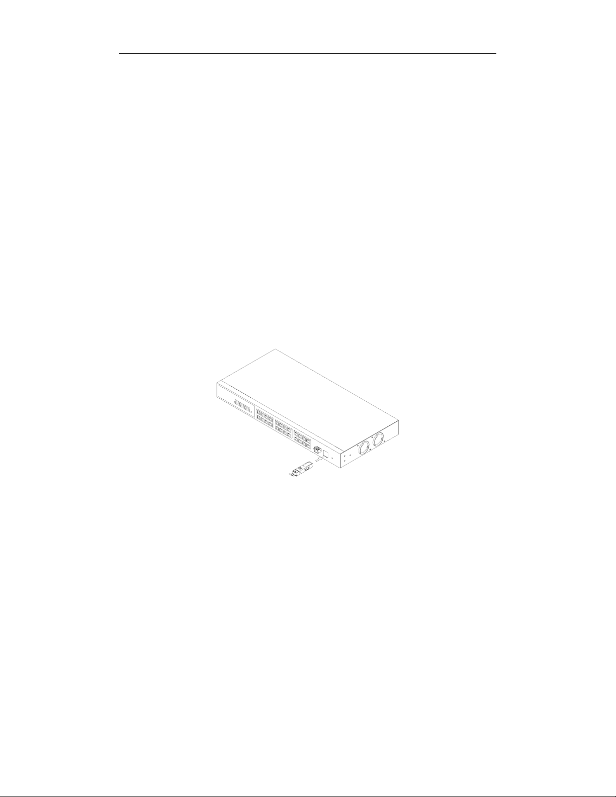
• Installing Optional SFP Fiber Transceivers to the 24 Gigabit Web Smart
Switch
Note: If you have no modules, please skip this section.
• Connecting the SFP Module to the Chassis:
The optional SFP modules are hot swappable, so you can plug or unplug it
before or after powering on.
1. Verify that the SFP module is the right model and conforms to the chassis
2. Slide the module along the slot. Also be sure that the module is properly
seated against the slot socket/connector
3. Install the media cable for network connection
4. Repeat the above steps, as needed, for each module to be installed into
slot(s)
5. Have the power ON after the above procedures are done
Publication date: January, 2005
Revision A1
Fig. 2-1 Installation of Optional SFP Fiber Transceive
8

User Manual
• TP Port and Cable Installation
⇒ In the switch, TP port supports MDI/MDI-X auto-crossover, so both types of
cable, straight-through (Cable pin-outs for RJ-45 jack 1, 2, 3, 6 to 1, 2, 3, 6 in
10/100M TP; 1, 2, 3, 4, 5, 6, 7, 8 to 1, 2, 3, 4, 5, 6, 7, 8 in Gigabit TP) and
crossed-over (Cable pin-outs for RJ-45 jack 1, 2, 3, 6 to 3, 6, 1, 2) can be used.
It means you do not have to tell from them, just plug it.
⇒ Use Cat. 5 grade RJ-45 TP cable to connect to a TP port of the switch and the
other end is connected to a network-aware device such as a workstation or a
server.
⇒ Repeat the above steps, as needed, for each RJ-45 port to be connected to a
Gigabit 10/100/1000 TP device.
Now, you can start having the switch in operation.
• Power On
The switch supports 100-240 VAC, 50-60 Hz power supply. The power
supply will automatically convert the local AC power source to DC power. It does not
matter whether any connection plugged into the switch or not when power on, even
modules as well. After the power is on, all LED indicators will light up immediately
and then all off except the power LED still keeps on. This represents a reset of the
system.
• Firmware Loading
After resetting, the bootloader will load the firmware into the memory. It will
take about 30 seconds, after that, the switch will flash all the LED once and
automatically performs self-test and is in ready state.
2-1-2. Cabling Requirements
To help ensure a successful installation and keep the network performance
good, please take a care on the cabling requirement. Cables with worse
specification will render the LAN to work poorly.
Publication date: January, 2005
Revision A1
9

User Manual
2-1-2-1. Cabling Requirements for TP Ports
⇒ For Fast Ethernet TP network connection
The grade of the cable must be Cat. 5 or Cat. 5e with a maximum length of
100 meters.
⇒ Gigabit Ethernet TP network connection
The grade of the cable must be Cat. 5 or Cat. 5e with a maximum length of
100 meters. Cat. 5e is recommended.
2-1-2-2. Cabling Requirements for 1000SX/LX SFP Module
It is more complex and comprehensive contrast to TP cabling in the fiber
media. Basically, there are two categories of fiber, multi mode (MM) and single
mode (SM). The later is categorized into several classes by the distance it supports.
They are SX, LX, LHX, XD, and ZX. From the viewpoint of connector type, there
mainly are LC and BIDI SC.
Gigabit Fiber with multi-mode LC SFP module
Gigabit Fiber with single-mode LC SFP module
Gigabit Fiber with BiDi SC 1310nm SFP module
Gigabit Fiber with BiDi SC 1550nm SFP module
The following table lists the types of fiber that we support and those else not
listed here are available upon request.
Multi-mode Fiber Cable and Modal Bandwidth
IEEE 802.3z
Gigabit Ethernet
1000SX 850nm
1000BaseLX/LHX/XD/ZX
1000Base-LX
Single Fiber
(BIDI SC)
Table2-1
Multi-mode 62.5/125µm Multi-mode 50/125µm
Modal
Bandwidth
160MHz-Km 220m 400MHz-Km 500m
200MHz-Km 275m 500MHz-Km 550m
Single-mode Fiber 9/125µm
Single-mode transceiver 1310nm 10Km
Single-mode transceiver 1550nm 30, 50Km
Single-Mode
Single-Mode
Distance
*20Km
*20Km
Modal
Bandwidth
TX(Transmit) 1310nm
RX(Receive) 1550nm
TX(Transmit) 1550nm
RX(Receive) 1310nm
Distance
Publication date: January, 2005
Revision A1
10
User Manual
2-1-2-3. Switch Cascading in Topology
• Takes the Delay Time into Account
Theoretically, the switch partitions the collision domain for each port in switch
cascading that you may up-link the switches unlimitedly. In practice, the network
extension (cascading levels & overall diameter) must follow the constraint of the
IEEE 802.3/802.3u/802.3z and other 802.1 series protocol specifications, in which
the limitations are the timing requirement from physical signals defined by 802.3
series specification of Media Access Control (MAC) and PHY, and timer from some
OSI layer 2 protocols such as 802.1d, 802.1q, LACP and so on.
The fiber, TP cables and devices’ bit-time delay (round trip) are as follows:
1000Base-X TP, Fiber 100Base-TX TP 100Base-FX Fiber
Round trip Delay: 4096 Round trip Delay: 512
Cat. 5 TP Wire: 11.12/m Cat. 5 TP Wire: 1.12/m Fiber Cable: 1.0/m
Fiber Cable : 10.10/m TP to fiber Converter: 56
Bit Time unit : 1ns (1sec./1000 Mega bit)
Bit Time unit: 0.01µs (1sec./100 Mega bit)
Table 2-2
Sum up all elements’ bit-time delay and the overall bit-time delay of
wires/devices must be within Round Trip Delay (bit times) in a half-duplex network
segment (collision domain). For full-duplex operation, this will not be applied. You
may use the TP-Fiber module to extend the TP node distance over fiber optic and
provide the long haul connection.
• Typical Network Topology in Deployment
A hierarchical network with minimum levels of switch may reduce the timing
delay between server and client station. Basically, with this approach, it will
minimize the number of switches in any one path; will lower the possibility of
network loop and will improve network efficiency. If more than two switches are
connected in the same network, select one switch as Level 1 switch and connect all
other switches to it at Level 2. Server/Host is recommended to connect to the Level
1 switch. This is general if no VLAN or other special requirements are applied.
11
Publication date: January, 2005
Revision A1
User Manual
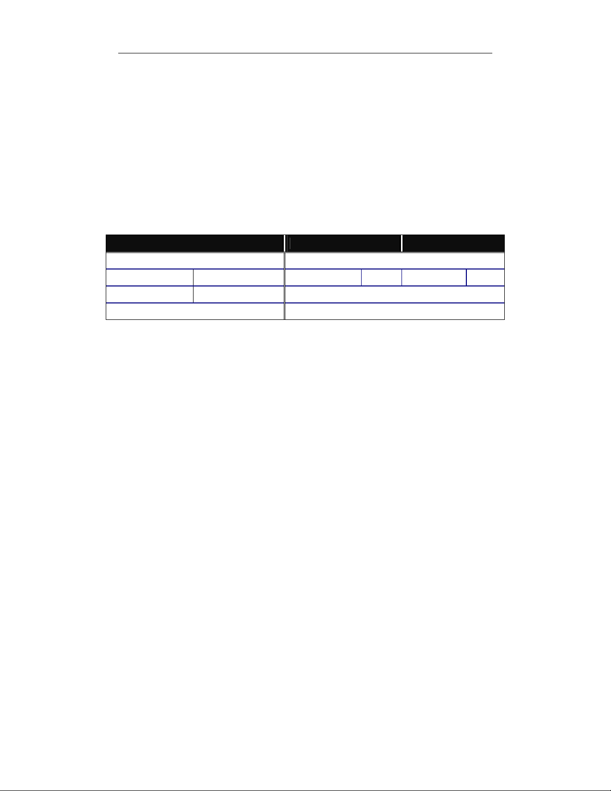
Case1: All switch ports are in the same local area network. Every port can access
each other (See Fig. 2-2).
Fig. 2-2 No VLAN Configuration Diagram
If VLAN is enabled and configured, each node in the network that can
communicate each other directly is bounded in the same VLAN area.
Here VLAN area is defined by what VLAN you are using. The switch
supports both port-based VLAN and tag-based VLAN. They are different in practical
deployment, especially in physical location. The following diagram shows how it
works and what the difference they are.
Case2a: Port-based VLAN (See Fig.2-3).
1. The same VLAN members could not be in different switches.
2. Every VLAN members could not access VLAN members each other.
3. The switch manager has to assign different names for each VLAN groups
at one switch.
Publication date: January, 2005
Revision A1
Fig. 2-3 Port-based VLAN Diagram
12
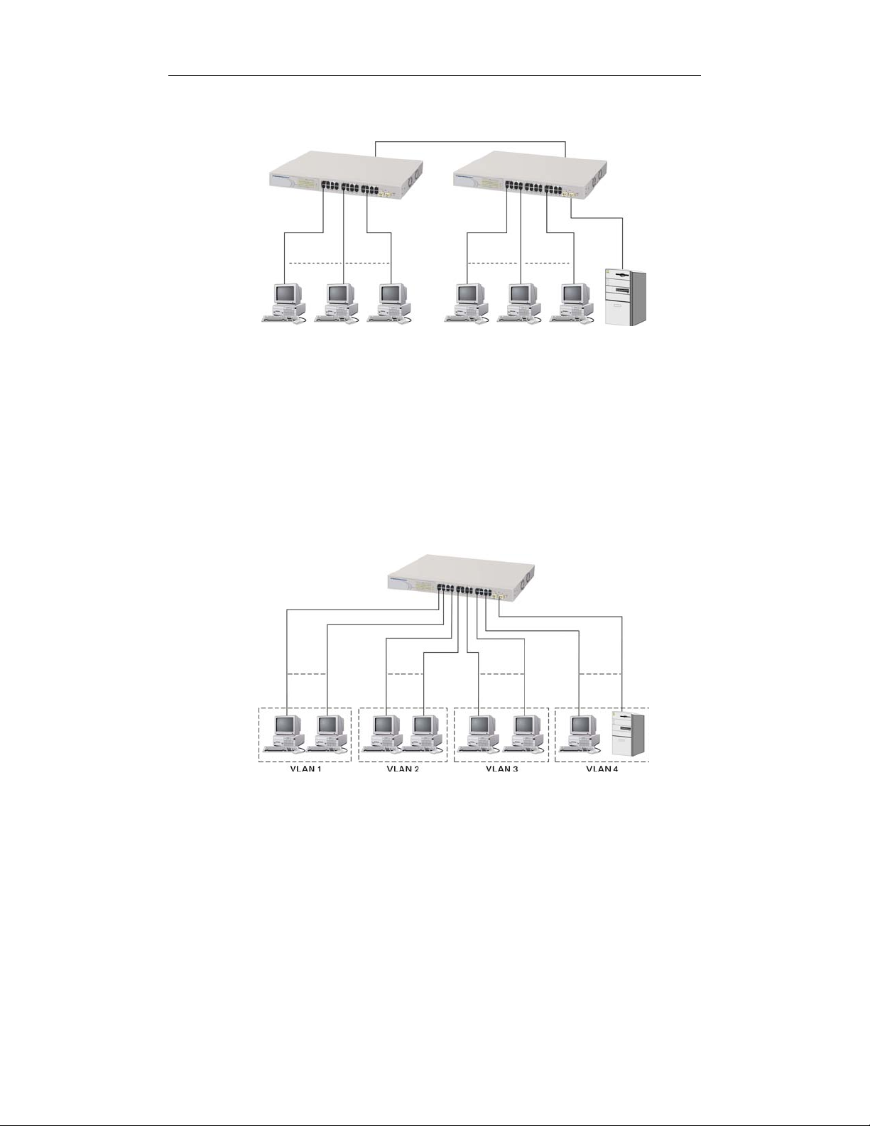
Case 2b: Port-based VLAN (See Fig.2-4).
User Manual
Fig. 2-4 Port-based VLAN Diagram
1. VLAN1 members could not access VLAN2, VLAN3 and VLAN4 members.
2. VLAN2 members could not access VLAN1 and VLAN3 members, but they could
access VLAN4 members.
3. VLAN3 members could not access VLAN1, VLAN2 and VLAN4.
4. VLAN4 members could not access VLAN1 and VLAN3 members, but they could
access VLAN2 members.
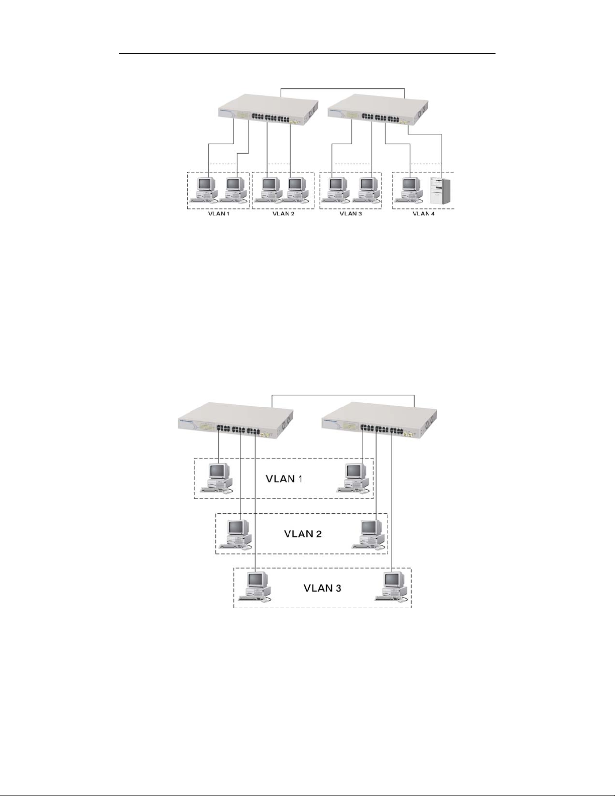
Case3a: The same VLAN members can be at different switches with the same VID
(See Fig. 2-5).
Fig. 2-5 Attribute-based VLAN Diagram
Publication date: January, 2005
Revision A1
13

User Manual
2-1-3. Configuring the Management Agent of 24 Gigabit Web Smart
Switch
In the way of web, user is allowed to startup the switch management function.
Users can use any one of them to monitor and configure the switch. You can touch
them through the following procedures.
Section 2-1-3-1: Configuring Management Agent of 24 Gigabit Web Smart Switch
through Ethernet Port
Publication date: January, 2005
Revision A1
14
User Manual
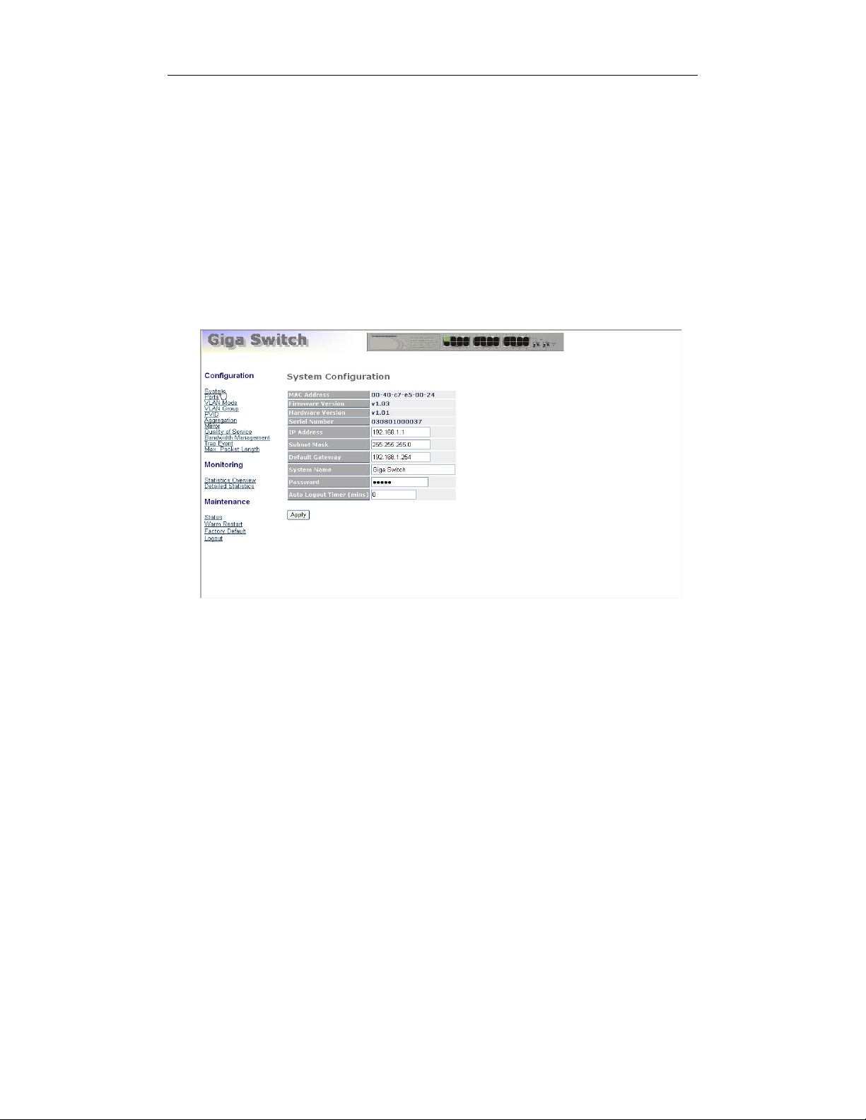
2-1-3-1. Configuring Management Agent of 24 Gigabit Web Smart Switch
through Ethernet Port
There are two ways to configure and monitor the switch through the switch’s
Ethernet port. They are Web browser and SNMP manager. The user interface for
the last one is NMS dependent and does not cover here. We just introduce the first
type of management interface. Web-based UI for the switch is an interface in a
highly friendly way.
Fig. 2-6
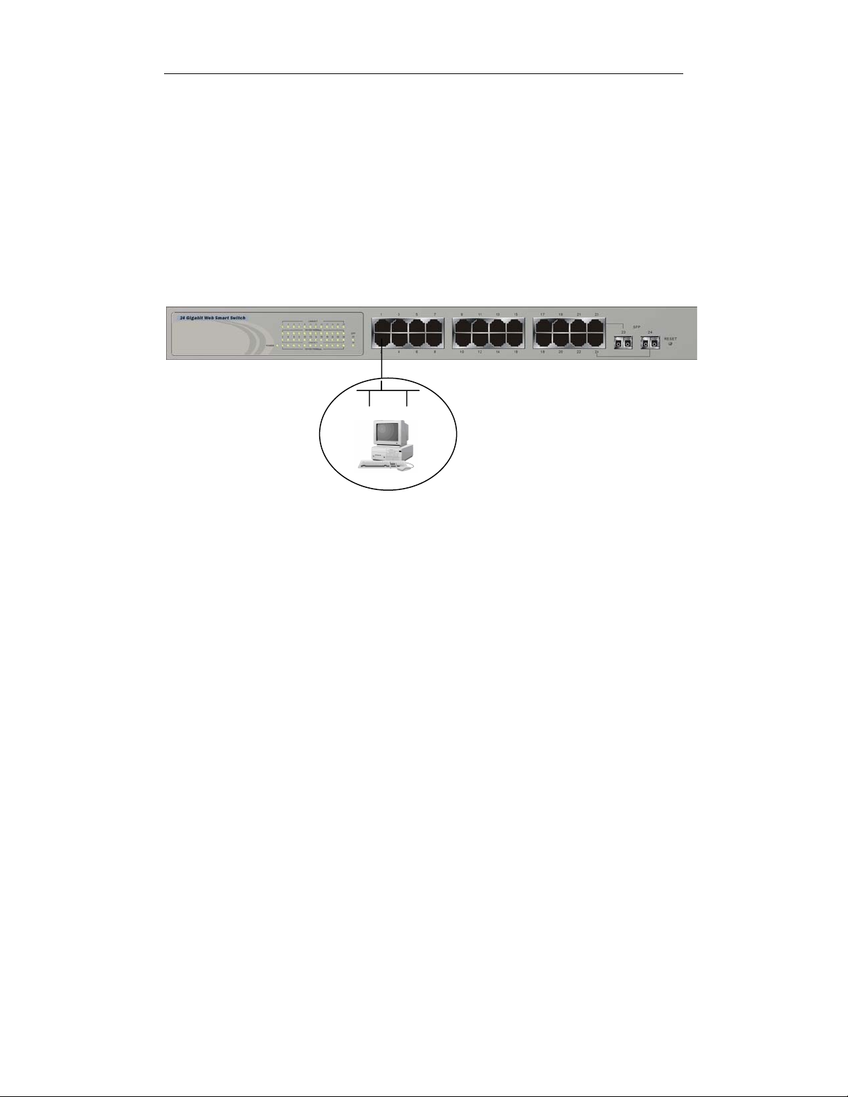
• Managing 24 Gigabit Web Smart Switch through Ethernet Port
Before you communicate with the switch, you have to finish first the
configuration of the IP address or to know the IP address of the switch. Then,
follow the procedures listed below.
1. Set up a physical path between the configured the switch and a PC
by a qualified UTP Cat. 5 cable with RJ-45 connector.
24 Gigabit Web Smart Switch
Default IP Setting:
IP = 192.168.1.1
Subnet Mask = 255.255.255.0
Default Gateway = 192.168.1.254
Assign a reasonable IP address,
For example:
Ethernet LAN
IP = 192.168.1.100
Subnet Mask = 255.255.255.0
Default Gateway = 192.168.1.254
Note: If PC directly connects to the switch, you have to setup the
same subnet mask between them. But, subnet mask may be
different for the PC in the remote site. Please refer to Fig. 2-6 about
the 24 Gigabit Web Smart Switch default IP address information.
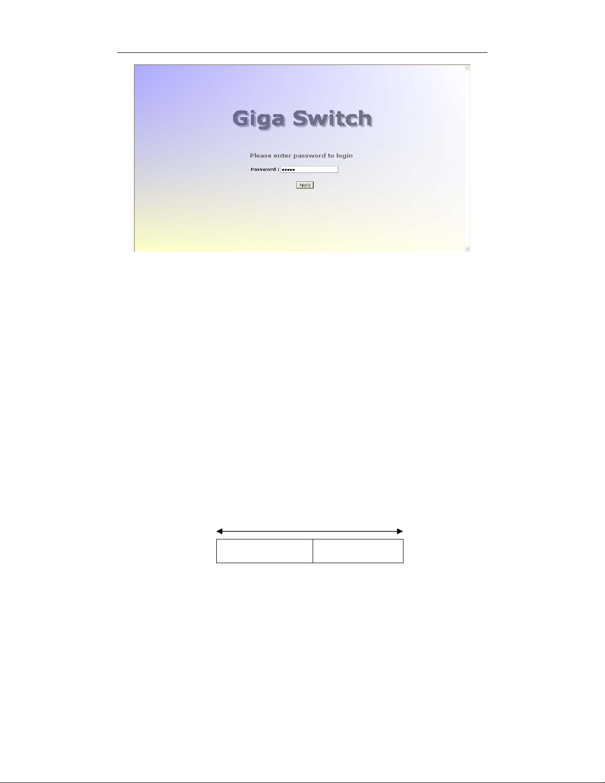
2. Run web browser and follow the menu. Please refer to Chapter 4.
Publication date: January, 2005
Revision A1
15
User Manual
Fig. 2-7 the Login Screen for Web
2-1-4. IP Address Assignment
For IP address configuration, there are three parameters needed to be filled
in. They are IP address, Subnet Mask, Default Gateway and DNS.
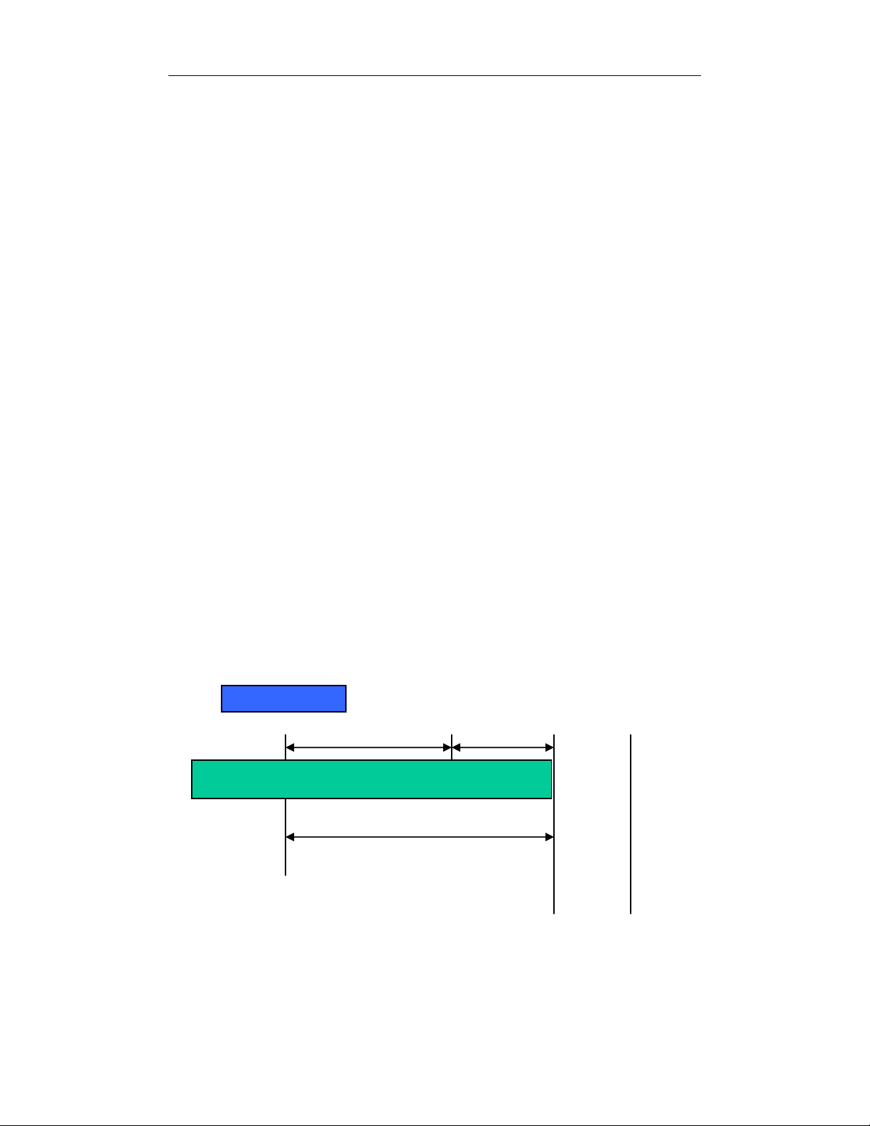
IP address:
The address of the network device in the network is used for internetworking
communication. Its address structure looks is shown in the Fig. 2-8. It is “classful”
because it is split into predefined address classes or categories.
Each class has its own network range between the network identifier and
host identifier in the 32 bits address. Each IP address comprises two parts: network
identifier (address) and host identifier (address). The former indicates the network
where the addressed host resides, and the latter indicates the individual host in the
network which the address of host refers to. And the host identifier must be unique
in the same LAN. Here the term of IP address we used is version 4, known as IPv4.
32 bits
Network identifier Host identifier
Fig. 2-8 IP address structure
Publication date: January, 2005
Revision A1
16

User Manual
With the classful addressing, it divides IP address into three classes, class A,
class B and class C. The rest of IP addresses are for multicast and broadcast. The
bit length of the network prefix is the same as that of the subnet mask and is
denoted as IP address/X, for example, 192.168.1.0/24. Each class has its address
range described below.
Class A:
Address is less than 126.255.255.255. There are a total of 126 networks can
be defined because the address 0.0.0.0 is reserved for default route and
127.0.0.0/8 is reserved for loopback function.
Bit # 0 1 7 8 31
0
Network address Host address
Class B:
IP address range between 128.0.0.0 and 191.255.255.255. Each class B
network has a 16-bit network prefix followed 16-bit host address. There are 16,384
(2^14)/16 networks able to be defined with a maximum of 65534 (2^16 –2) hosts
per network.
Bit # 01 2 15 16 31
10
Network address Host address
Class C:
IP address range between 192.0.0.0 and 223.255.255.255. Each class C
network has a 24-bit network prefix followed 8-bit host address. There are
2,097,152 (2^21)/24 networks able to be defined with a maximum of 254 (2^8 –2)
hosts per network.
Bit # 0 1 2 3 23 24 31
110
Network address Host address
17
Publication date: January, 2005
Revision A1
User Manual
t
N
k
Class D and E:
Class D is a class with first 4 MSB (Most significance bit) set to 1-1-1-0 and
is used for IP Multicast. See also RFC 1112. Class E is a class with first 4 MSB set
to 1-1-1-1 and is used for IP broadcast.
According to IANA (Internet Assigned Numbers Authority), there are three
specific IP address blocks reserved and able to be used for extending internal
network. We call it Private IP address and list below:
Class A 10.0.0.0 --- 10.255.255.255
Class B 172.16.0.0 --- 172.31.255.255
Class C 192.168.0.0 --- 192.168.255.255
Please refer to RFC 1597 and RFC 1466 for more information.
Subnet mask:
It means the sub-division of a class-based network or a CIDR block. The
subnet is used to determine how to split an IP address to the network prefix and the
host address in bitwise basis. It is designed to utilize IP address more efficiently and
ease to manage IP network.
For a class B network, 128.1.2.3, it may have a subnet mask 255.255.0.0 in
default, in which the first two bytes is with all 1s. This means more than 60
thousands of nodes in flat IP address will be at the same network. It’s too large to
manage practically. Now if we divide it into smaller network by extending network
prefix from 16 bits to, say 24 bits, that’s using its third byte to subnet this class B
network. Now it has a subnet mask 255.255.255.0, in which each bit of the first
three bytes is 1. It’s now clear that the first two bytes is used to identify the class B
network, the third byte is used to identify the subnet within this class B network and,
of course, the last byte is the host number.
Not all IP address is available in the sub-netted network. Two special
addresses are reserved. They are the addresses with all zero’s and all one’s host
number. For example, an IP address 128.1.2.128, what IP address reserved will be
looked like? All 0s mean the network itself, and all 1s mean IP broadcast.
10000000.00000001.00000010.1 0000000
Publication date: January, 2005
Revision A1
etwor
25 bits
All 0s = 128.1.2.128
All 1s= 128.1.2.255
18
Subne
1 0000000
1 1111111
User Manual
In this diagram, you can see the subnet mask with 25-bit long,
255.255.255.128, contains 126 members in the sub-netted network. Another is that
the length of network prefix equals the number of the bit with 1s in that subnet mask.
With this, you can easily count the number of IP addresses matched. The following
table shows the result.
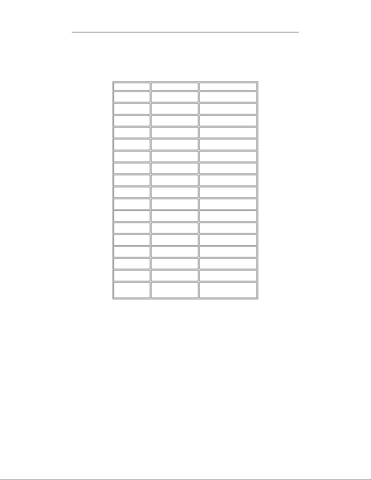
Prefix Length No. of IP matched No. of Addressable IP
/32
1 -
/31
/30
/29
/28
/27
/26
/25
/24
/23
/22
/21
/20
/19
/18
/17
2 -
4 2
8 6
16 14
32 30
64 62
128 126
256 254
512 510
1024 1022
2048 2046
4096 4094
8192 8190
16384 16382
32768 32766
/16
65536 65534
Table 2-3
According to the scheme above, a subnet mask 255.255.255.0 will partition a
network with the class C. It means there will have a maximum of 254 effective
nodes existed in this sub-netted network and is considered a physical network in an
autonomous network. So it owns a network IP address which may looks like
168.1.2.0.
With the subnet mask, a bigger network can be cut into small pieces of
network. If we want to have more than two independent networks in a worknet, a
partition to the network must be performed. In this case, subnet mask must be
applied.
Publication date: January, 2005
Revision A1
19
User Manual
For different network applications, the subnet mask may look like
255.255.255.240. This means it is a small network accommodating a maximum of
15 nodes in the network.
Default gateway:
For the routed packet, if the destination is not in the routing table, all the
traffic is put into the device with the designated IP address, known as default router.
Basically, it is a routing policy.
For assigning an IP address to the switch, you just have to check what the IP
address of the network will be connected with the switch. Use the same network
address and append your host address to it.
Fig. 2-9
First, IP Address: as shown in the Fig. 2-9, enter “192.168.1.1”, for instance.
For sure, an IP address such as 192.168.1.x must be set on your PC.
Second, Subnet Mask: as shown in the Fig. 2-9, enter “255.255.255.0”. Any
subnet mask such as 255.255.255.x is allowable in this case.
Publication date: January, 2005
Revision A1
20
User Manual
2-2. Typical Applications
The 24 Gigabit Web Smart Switch implements 24 Gigabit Ethernet TP ports
with auto MDIX and two slots for the removable module supporting comprehensive
fiber types of connection, including LC and BiDi-LC SFP modules. For more details
on the specification of the switch, please refer to Appendix A.
The switch is suitable for the following applications.
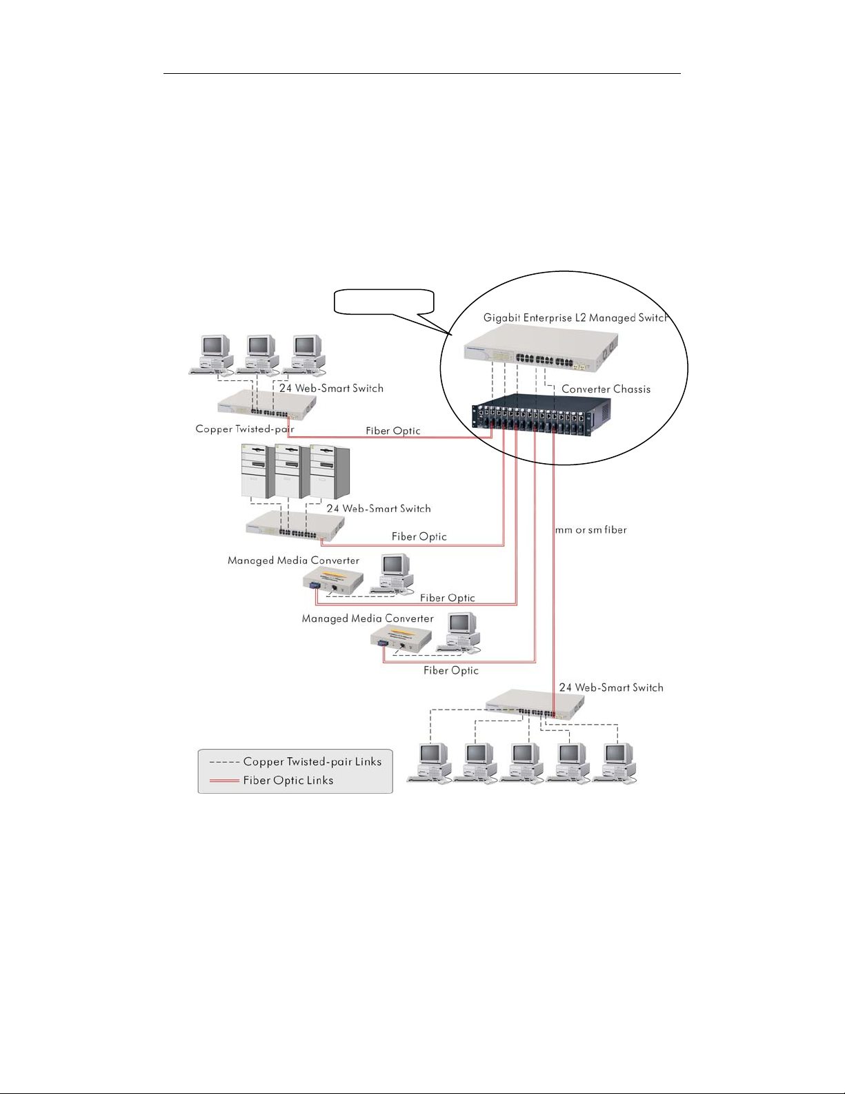
Central Site/Remote site application is used in carrier or ISP (See Fig. 2-10)
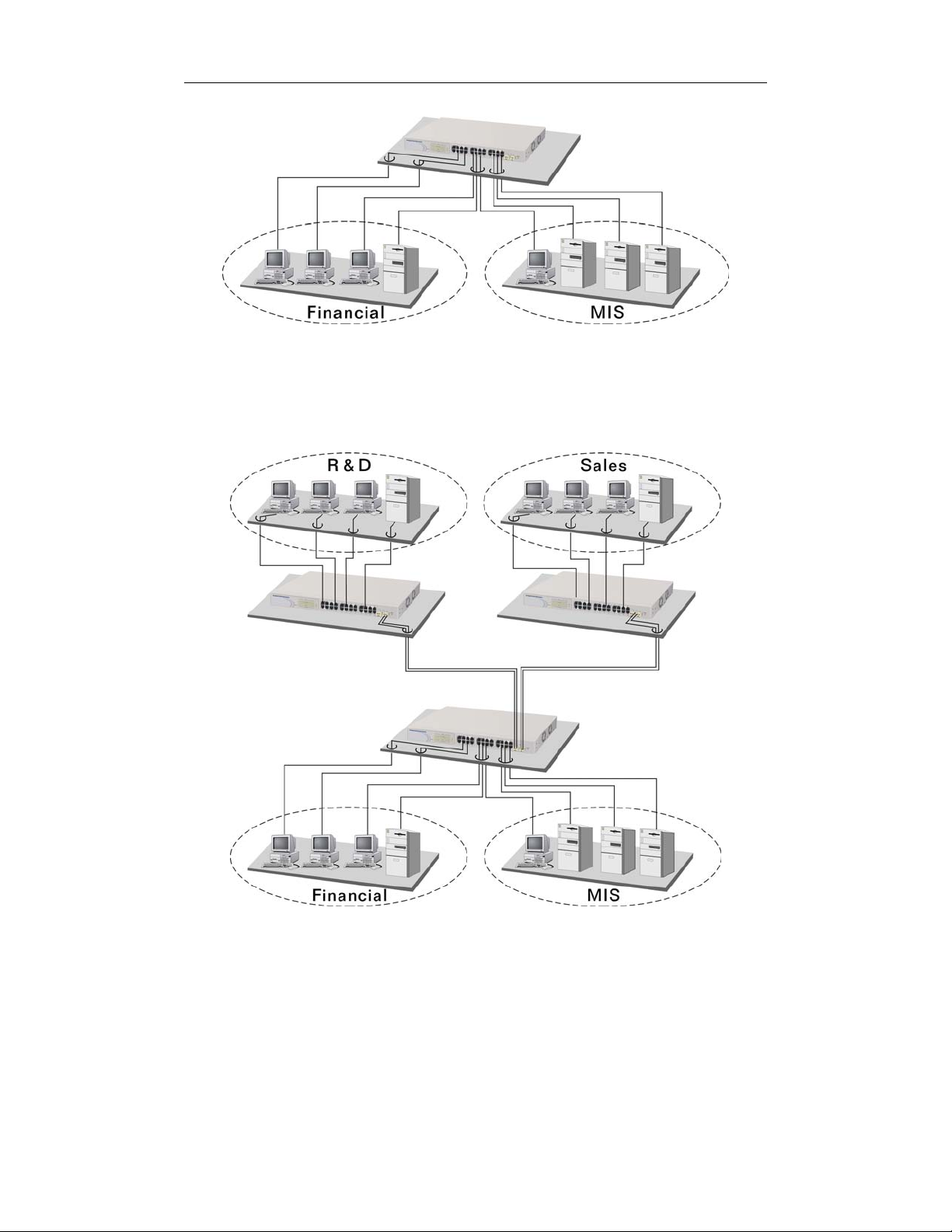
Peer-to-peer application is used in two remote offices (See Fig. 2-11)
Office network(See Fig. 2-12)
Central Site
Fig. 2-10 Network Connection between Remote Site and Central Site
Fig. 2-10 is a system wide basic reference connection diagram. This diagram
demonstrates how the switch connects with other network devices and hosts.
Publication date: January, 2005
Revision A1
21
User Manual
Fig. 2-11 Peer-to-peer Network Connection
Fig. 2-12 Office Network Connection
Publication date: January, 2005
Revision A1
22
 Loading...