

Page 1
Trademarks
Contents subject to revision without prior notice.
All trademarks remain the property of their respective
owners.
Copyright Statement
This publication may not be reproduced as a whole or in
part, in any way whatsoever unless prior consent has been
obtained from owner.
FCC Compliance Statement
This equipment has been tested and found to comply
with the limits for a Class B digital device, pursuant to
Part 15 of the FCC Rules. These limits are designed to
provide reasonable protection against harmful
interference when the equipment is operated in a
commercial or residential environment. This equipment
generates, uses, and can radiate radio frequency energy
and, if not installed and used in accordance with this
User’s Guide, may cause harmful interference to radio
communications.
1. Checklist
The GC-H21 carton should contain following items:
⎯ GC-H21 Converter
⎯ AC-DC Power Adapter
⎯ This User’s Guide
Please notify your sales representative immediately if any
items are missing or damaged.
2. Overview
GC-H21 is designed to meet the needs for optical fiber
network deployment and able to extend a legacy copper
based network via fiber cable to a maximum distance of up
to 100KM (Max. distance varies depending on the model).
GC-H21
is fully compliant with IEEE 802.3 & 802.3u
standards; built-in Switching ASIC has turned GC-H21
function more like a 2 ports switch than a traditional
converter. User can get all switching benefits such like
traffic segmentation, frames checking & error filtering. In
addition, Link-Cross-Check allow user to monitor &
maintain their critical fiber link more easily and effectively.
The installation & operation procedures of the GC-H21 are
simple & straightforward. Operation status can be
monitored through a set of Diagnostic LED located in the
front panel.
FEATURES
• 10/100Base-TX to 100Base-FX converter
• Store & Forward switching mechanism
• Comply to IEEE 802.3, 802.3u
• MDI/MDIX Auto-Crossover supported
• Auto-Negotiation or Manual mode setting of Speed
& Duplex mode
• LED Indication
o Power, FDX,
o TX 100, TP Link/Activity
o FX 100, FX Link/Activity
• Link-Cross-Check function
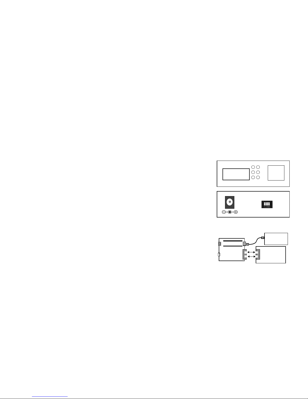
3. Installation
The installation procedure is simple and straightforward.
• Attach fiber cable from the GC-H21 to the fiber
network.
• Attach UTP cable from the 10/100Base-TX network
to the RJ-45 port on the GC-H21.
• Connect the power adapter to the GC-H21 and check
that the Power LED lights up. The TX Link and FX
Link LED will light when all the cable connections are
satisfactory.
100
LINK/
A
CT
FX TX
FDX PWR
Fig. 1 GC-H21 Converter Front & Rear Panel
5VDC IN
10/10 0 BASE- T X
Network
SC/ST
Fiber
Network
TX
RX
RX
TX
Fig. 2 Basic Network Connecti on
10/100BASE-TX
TX RX
Page 2
4. LED Description
5. Technical Specifications
Standards IEEE 802.3 & IEEE 802.3u
Switching Mechanism Store & Forward
MAC table 1K Entries
Forward & Filter Rate 10Base-T 14,800 pps
(64 Bytes) 100Base-TX 148,800 pps
LED Power, FDX, TP 100, TP Link/Act,
Fiber 100, Fiber Link/Act
Power DC 5V, 1.6A
Power Consumption 5W
Weight 0.6 Kg
Dimensions 26 X 71 X 94mm
Temperature Operating: 0 ~ 50
o
C
Storage: -20 ~ 60 oC
Humidity 5% ~ 90% RH
Safety UL, CSA
Emission FCC/CE Class B
UTP Cat. 5 UTP cable
Fiber 50/125, 62.5/125, or 100/140
µ
m multimode
8.3/125, 8.7/125, 9/125 or 10/125
µ
m single-mode
6. Rear Panel DIP Switch
Pin 1 Off/On TP Auto-negotiation Enable/Disable
Pin 2 Off/On TP Speed 100M/10M
Pin 3 Off/On TP Duplex Full / Half
Pin 4 Off/On Link-Cross-Check Disable/Enable
Default set OFF from PIN 1 to PIN 4
Please Note - Power-On reset must be performed
after changing the Dip Switch setting.
7. Link-Cross-Check
Link-Cross-Check allow user easily to identify and
diagnose the linking status. If set Link-Cross-Check switch
to Enable, UTP and Fiber port can link up only when both
linking conditions are good. In addition, if any of the fiber or
UTP port link down during operation, the other port will
also turn down link to alert the user and avoid packet loss.
Set Link-Cross-Check switch to Enable provide user
transparent link indication between two network devices
interconnected by GC-H21.
If Disable the Link-Cross-Check, the UTP and fiber port
will link up base on their individual linking condition.
Further, if fiber port link down during operation, it will not
turn down the UTP port link and vice versa.
8. Pure Converter Mode
This converter can also set to operate as a pure converter
without switching function by applying the following
settings:
Connecting to a 100Mbps Full Duplex:
Link-Cross-Check Enable (Pin 4 On)
TP Speed to 100Mbps (Pin 2 Off)
TP Duplex to Full (Pin 3 Off)
Connecting to a 100Mbps Half Duplex:
Link-Cross-Check Enable (Pin 4 On)
TP Speed to 100Mbps (Pin 2 Off)
TP Duplex to Half (Pin 3 On)
Ordering Information
Multi-mode
GC-H21SC: SC/1310nm/2Km
GC-H21ST: ST/1310nm/2Km
GC-H21MR: MT-RJ/1310nm/2Km
Single-mode
GC-H21SCS: SC/1310nm/10Km
GC-H21
Fast Ethernet
Switching Converter
User’s Guide
V 2.4
LED Color Function
PWR Green Lit when power is available
FX 100 Green Lit when FX port speed is 100M
FX Link/ACT Green
Blink
Lit when fiber link is up
Blink when traffic present
FDX Green Lit when TP port Full Duplex Mode
is enabled
TX 100 Green Lit when TP port speed is 100M
TX Link/ACT Green
Blink
Lit when TP link is up
Blink when traffic present
 Loading...