

Page 1

EMU Router User Manual: ER2000T
-XX-
CAT1
Connected IO Inc.,
CONFIDENTIAL
Emu Router
User Manual: ER2000T-XX-CAT1
Rev: V0. 6
2 nd
Au gust 20 1 7
Revision: 0.6
Page 2
Connected IO Inc.,
CONFIDENTIAL
2
EMU Router User Manual: ER2000T
-XX-
CAT1
Revision: 0.6
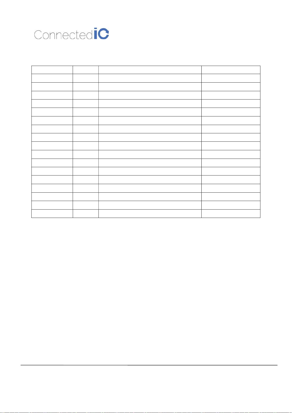
Revision History:
Date Rev No. Description By
07-10-2017 V0.1 Initial draft CIO
07-27-2017 V0.2 Numerous Updates CIO
07-28-2017 V0.3 Nomenclature clean-up CIO
07-28-2017 V0.4 Certification section clean-up CIO
08-01-2017 V0.5 Certification section clean-up CIO
08-02-2017 V0.6 Removed -VZ-CAT1 from the Manual CIO
Page 3

Connected IO Inc.,
CONFIDENTIAL
3
EMU Router User Manual: ER2000T
-XX-
CAT1
Revision: 0.6
Table of Contents
1. INTRODUCTION 5
2. Hardware Configuration 5
2.1. Product Interfaces 5
2.2. Radio Configurations 7
3. System Configuration 7
3.1. Initial IP Setup 7
3.2. Setup New IP 9
3.3. Enable/Disable the DHCP Server on LAN Interface 11
3.4. Connecting to the WiFi 12
4. System Maintenance 13
4.1. Backup the Configuration 13
4.2. Restore the Configuration 14
4.3. Reset to Factory Default under Web GUI 14
4.4. Firmware Upgrade 15
5. Modem 16
5.1. AT Command 17
5.2. APN Change 18
5.3. Mode Setting 19
6. LOG 19
6.1. System LOG 19
6.2. Kernel LOG 19
7. Antenna 20
7.1. Detachable Antenna Guidelines 20
7.2. Antenna – Installation Guidelines 20
7.3. Recommended Antennas 20
Page 4

Connected IO Inc.,
CONFIDENTIAL
4
EMU Router User Manual: ER2000T
-XX-
CAT1
Revision: 0.6
8. Environmental 21
8.1. Operating Environment 21
8.2. Physical Parameters 21
9. Approvals and Certifications 21
9.1. Manufacturing 21
9.2. North American Certifications 21
9.2.1. ER2000T-NA-CAT1 21
9.2.2. ER2000T-VZ-CAT1 22
9.3. FCC General Warning 22
9.4. Industry Canada (IC) Notices 24
Page 5
Connected IO Inc.,
CONFIDENTIAL
5
EMU Router User Manual: ER2000T
-XX-
CAT1
5 7
Revision: 0.6
1. Introduction
Connected IO Inc’s., Emu Router is a 4G router offering CAT1 connectivity for M2M applications. The
Emu router includes a 4G modem with an embedded host processor based on Mediatek MT7620A SoC
which also supports 802.11 b/g/n WiFi functionality. The 4G connectivity is made by an operator
certified LTE module.
This document provides instructions, and basic operational guidelines, to aid a Systems Administrator
with the deployment of this product.
2. Hardware Configuration
2.1. Product Interfaces
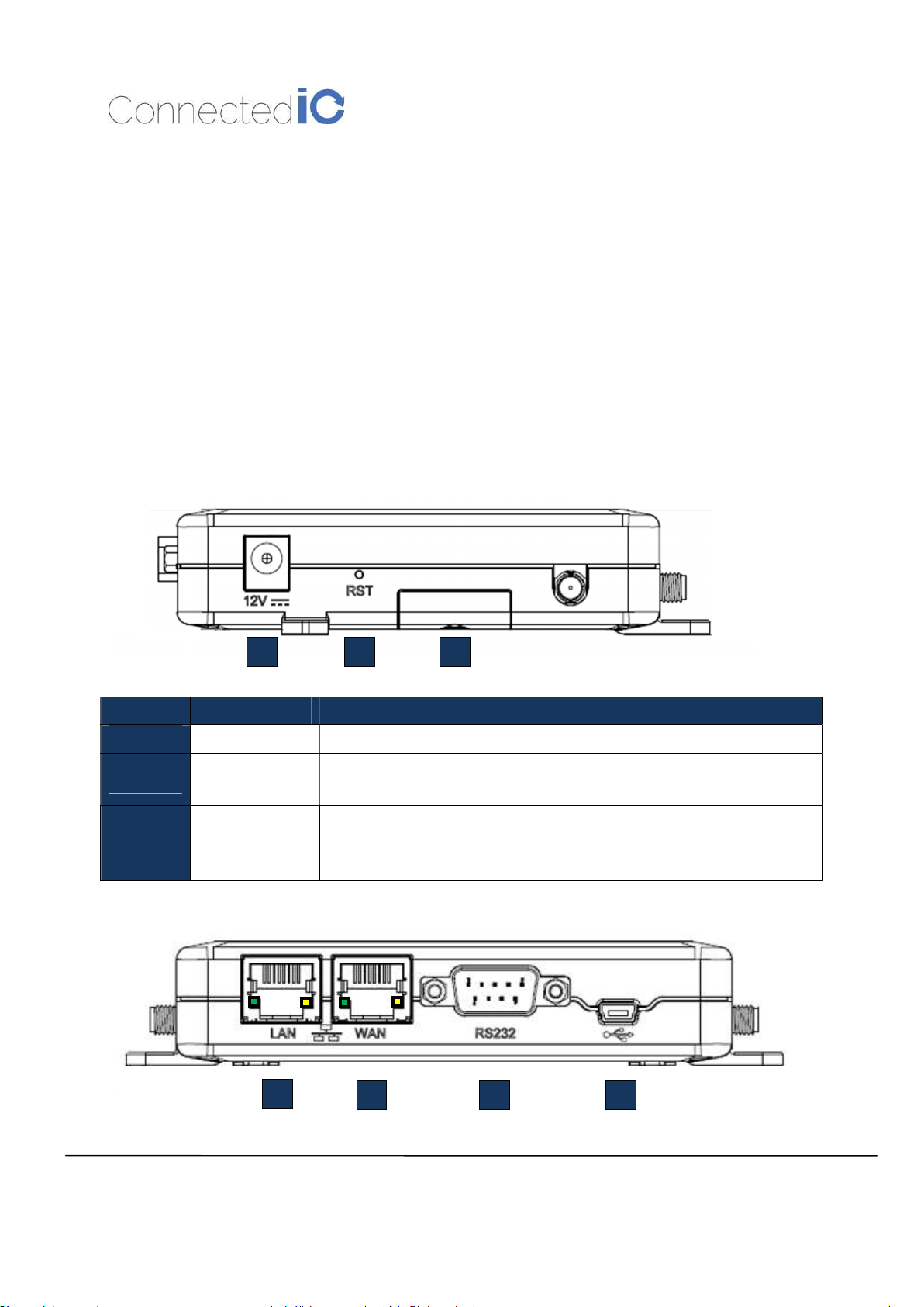
Number Item Description
1
2
3
1 DC Power Input 12VDC @ 2.0A Input. Center conductor is Positive
2 Reset Button
3
SIM Access
2 4
Push & Release to reset the device
Push & Hold for 5-seconds then release installs factory preset
2FF Mini-SIM format
Slide the door open to access the SIM holder.
Push SIM into the holder to engage, push a second time to eject the SIM
6
Page 6
Connected IO Inc.,
CONFIDENTIAL
6
EMU Router User Manual: ER2000T
-XX-
CAT1
8
Revision: 0.6
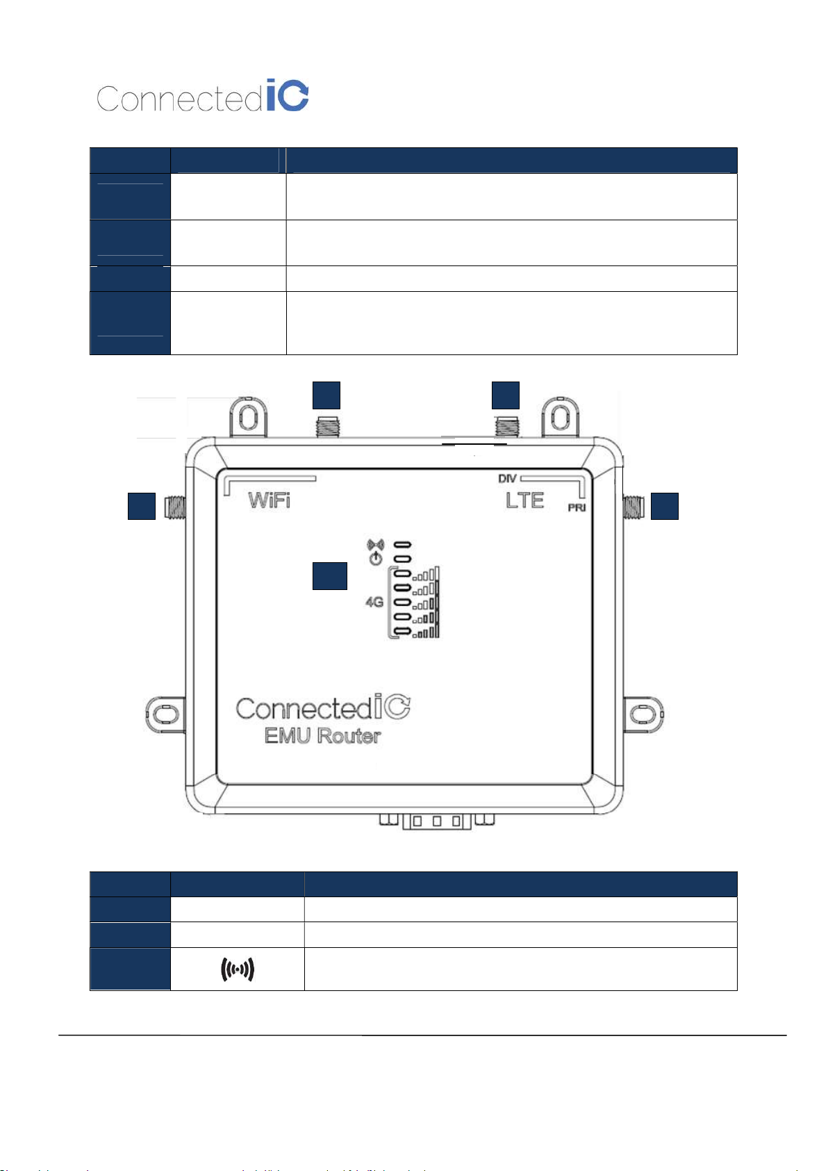
Number
4 LAN Port
5 WAN Port
Item Description
LAN Port for Wired Ethernet Clients
LED: Solid Green for Link, Flashing Yellow for Traffic
WAN Port for establishing links to leased telecommunication circuits
LED: Solid Green for Link, Flashing Yellow for Traffic
6 RS232 Port Serial Communications port per EIA asynchronous data transfer
Mini-USB 2.0 provides connectivity for optional storage or a USB
7 USB Port
Ethernet dongle.
Port supplies up to 0.5A of 5V to connected devices.
9
8
9
10
Number Item Description
8 WiFi Antenna SMA connector for WiFi Antennas (NOT Reverse Polarized)
9 Cellular Antennas SMA connector for both Primary and Diversity Antenna Ports
10
WiFi LED, Orange: Wifi is Connected/Off No WiFi/Flashing Orange
for traffic
Page 7
Radio Configurations
LTE Band
B2: 1900
B4: 1700/2100
B5: 850
B12:
B13: 700 c
Configuration
The Emu Router Management GUI can be accessed through the Ethernet ports
follow the following sequence:
e Ethernet cable between
static IP in
Open a browser and type http:
On login page, you can just click the Login icon to enter the GUI
it is recommended that a
Connected IO Inc.,
CONFIDENTI
A
L
EMU Router User Manual: ER2000T
Green
The following table lists the signal strength range corresponding to
PCS
with
LAN port
ain or DHCP client to get IP from
Figure
under Web GUI System
7
-XX-
CAT1
Revision: 0.6
2.2.
Model Name
ER2000T-NA-CAT1
Power LED, Yellow: On Power is good
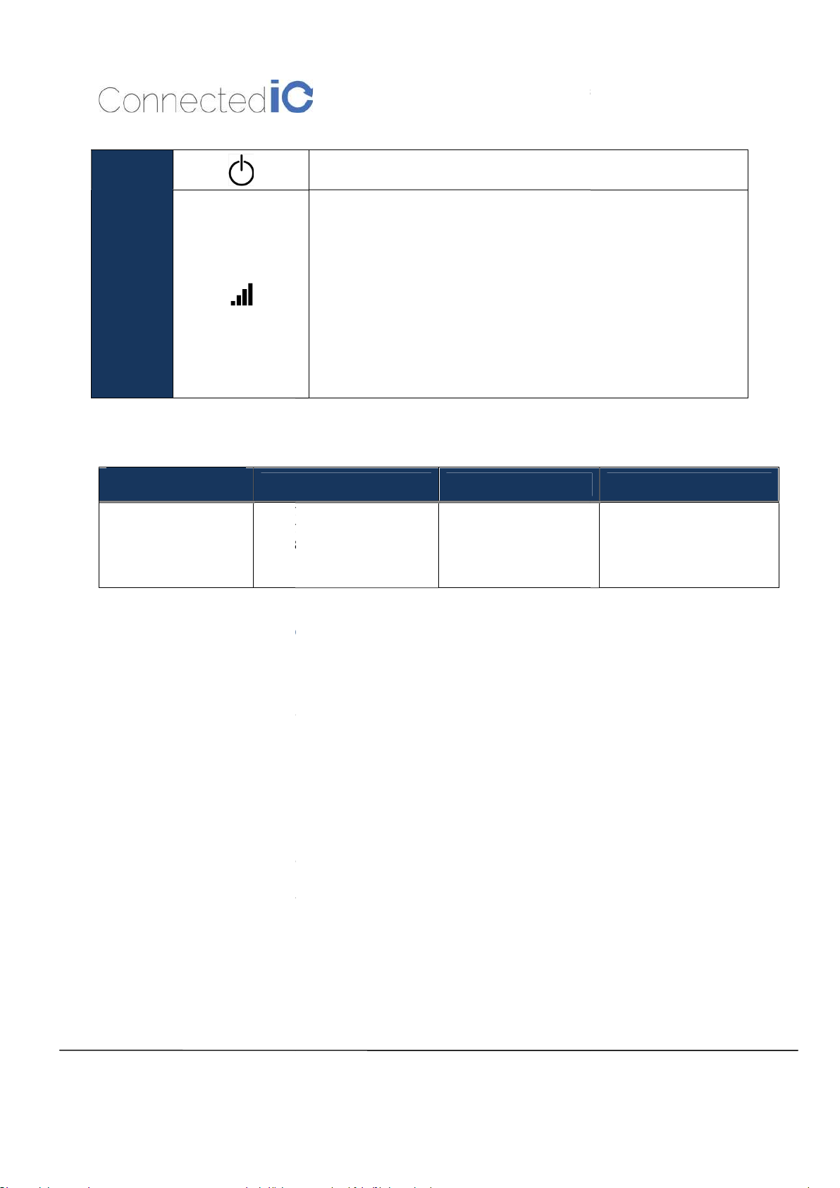
Cellcular Connection Strenght Indicators,
Connection
the number of LEDs lit:
5-LEDs On: > -61dBm
4-LEDs On: -63 dBm to -71 dBm
3-LEDs On: -73 dBm to -83 dBm
2-LEDs On: -85 dBm to -98 dBm
1-LED On: -97 dBm to -107 dBm
No-LEDs: < -109 dBm
: Cellcular
(MHz) 3G (MHz)
700 ac
AWS 1
B2: 1900
B5: 850
Yes, 802.11 b/g/n
compliant
WiFi
3. System
3.1. Initial IP Setup
address of 192.199.1.1.
To configure the Emu Router,
Connect th
Setup the desktop as a
is “password”,
>Administration page.
the computer and the Emu Router
192.199.1.x dom
// 192.199.1.1 to start the settings
as shown in
new password be created
the default IP
1. Default password
-
EMU Router
Page 8
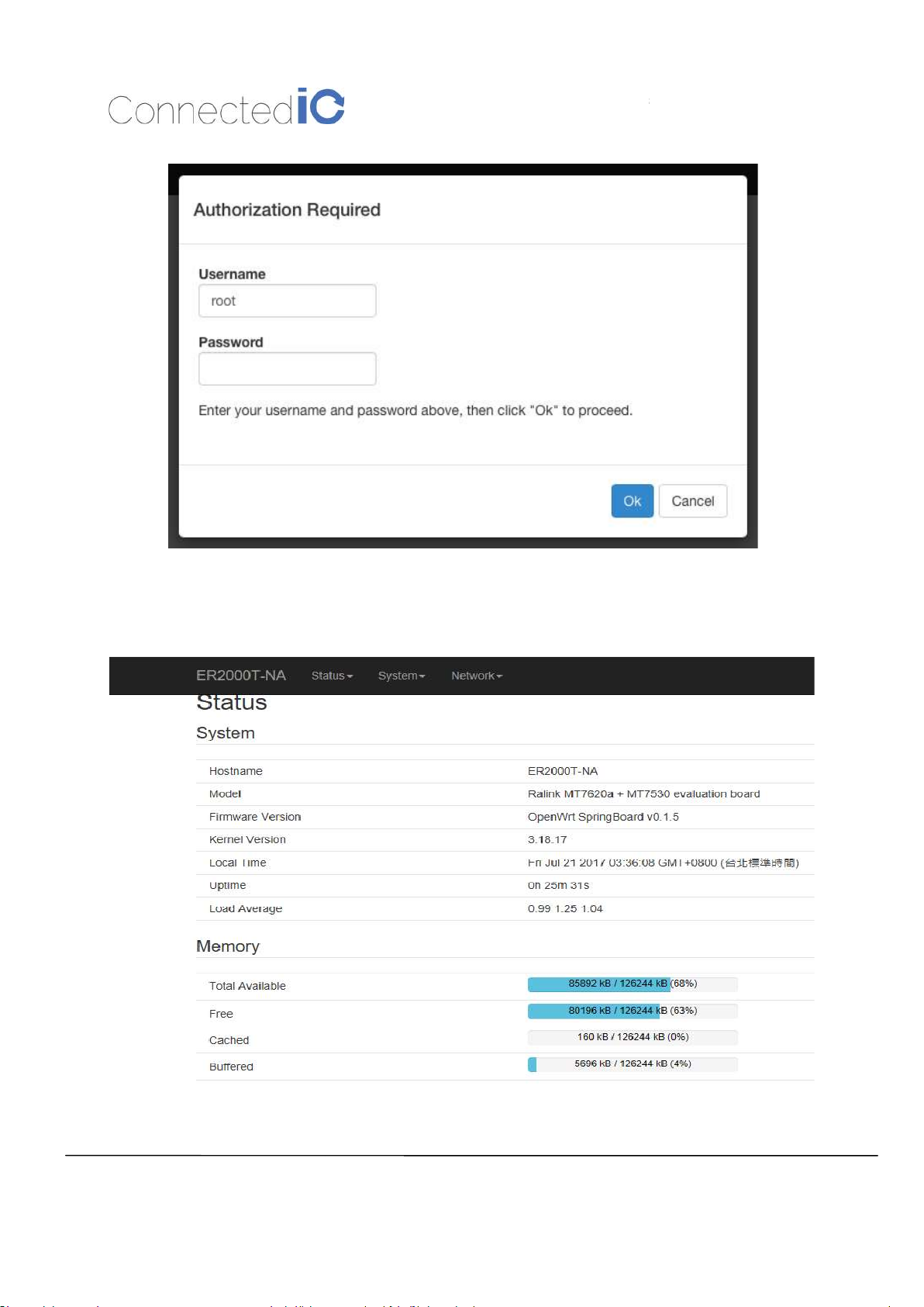
You can see the EMU Router overview after login
such as system status,
Connected IO Inc.,
CONFIDENTI
A
L
EMU Router User Manual: ER2000T
include
8
-XX-
CAT1
Figure 1: Login Page
Revision: 0.6
messages
into GUI, the overview page
and memory information as shown in Figure 2.
s important
Figure 2: Overview Page
Page 9
Connected IO Inc.,
CONFIDENTIAL
9
EMU Router User Manual: ER2000T
-XX-
CAT1
3.2. Setup New IP
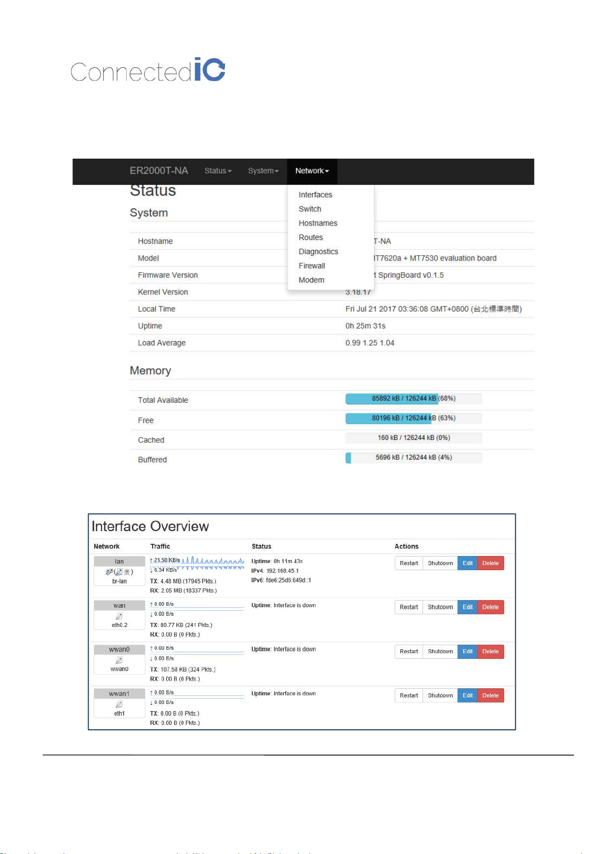
Select Network->Interfaces as shown in Figure 3.
Revision: 0.6
Select LAN and click “Edit” from Figure 4.
Figure 3: Network List
Page 10
Connected IO Inc.,
CONFIDENTIAL
10
EMU Router User Manual: ER2000T
-XX-
CAT1
Figure 4: Interface Overview
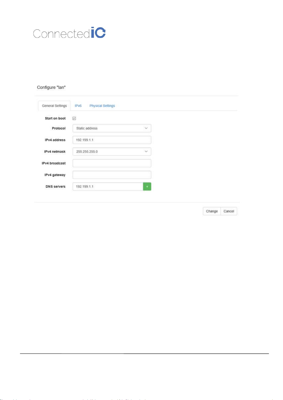
Enter the new IP address in the “IPv4 address” filed, and then click the “Change” icon in the bottom-
right corner in Figure 5.
Revision: 0.6
Figure 5: New IP Address for LAN
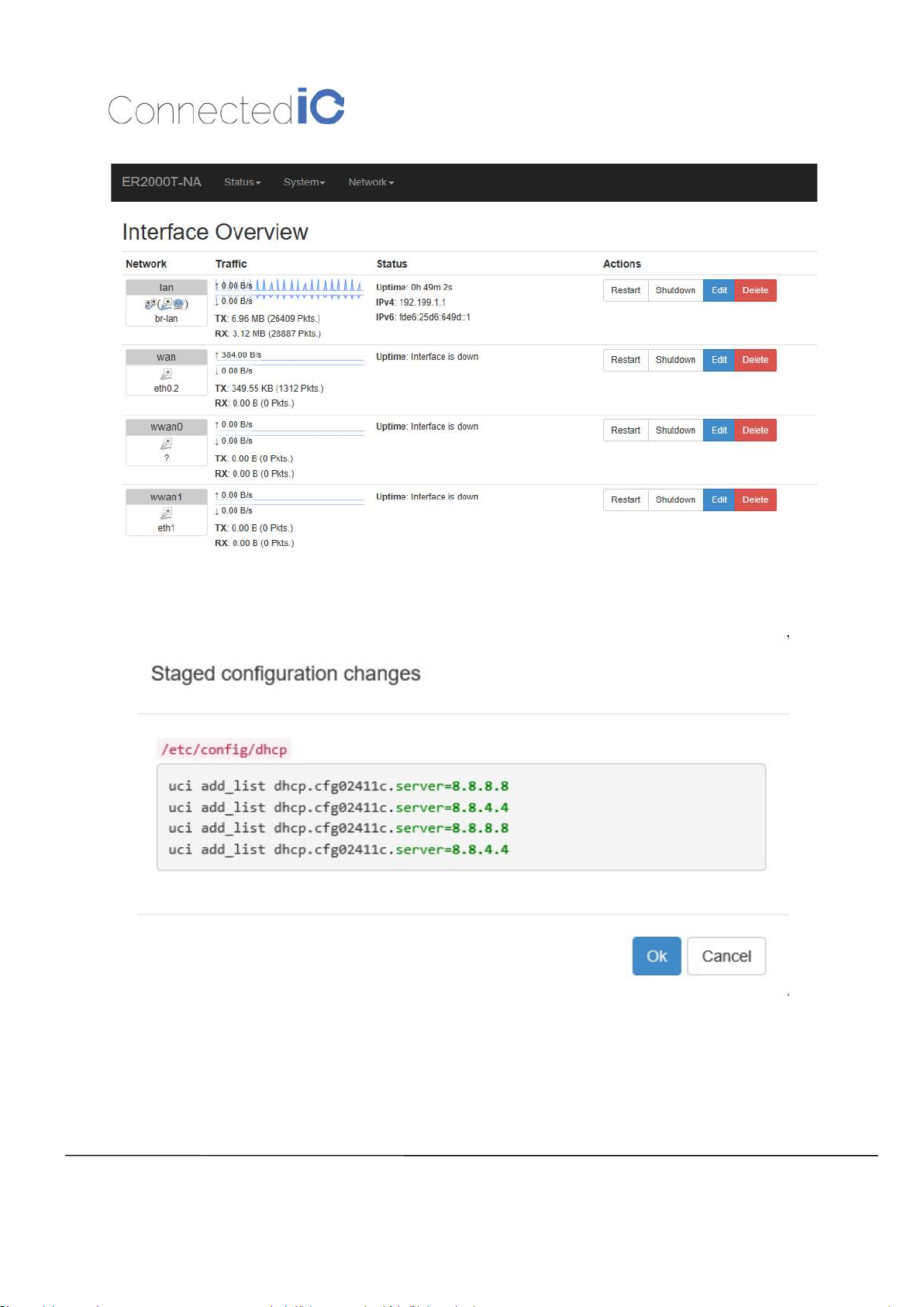
After setup new IP, the GUI will return to “Interface Overview”, you have to press “Apply” in the upper
right corner as shown in Figure 6.
Page 11
Connected IO Inc.,
CONFIDENTIAL
11
EMU Router User Manual: ER2000T
-XX-
CAT1
Figure 6: Save the New Setting
Revision: 0.6
After pressing “Apply”, the system will show a confirmation window. Please see Figure 7.
Figure 7: Configuration Change
3.3. Enable/Disable the DHCP Server on LAN Interface
[N.A]
Page 12
Connected IO Inc.,
CONFIDENTIAL
12
EMU Router User Manual: ER2000T
-XX-
CAT1
Revision: 0.6
3.4. Connecting to the WiFi
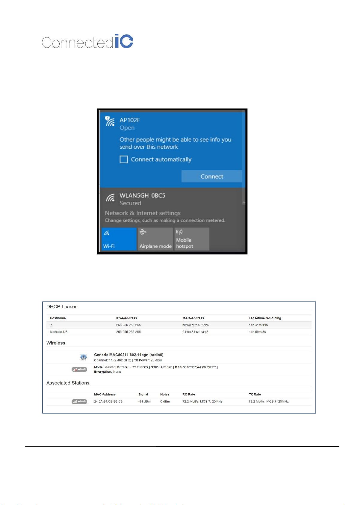
For computers using Windows operating system (For instance: Windows 10), Click the network internet
access icon and there are wireless networks in range, and try to connect to a WiFi “AP102F” network
without security key input as shown in Figure 6.
Figure 8 : Network Internet Access
Open a browser and typing http://192.199.1.1 to login into the GUI again. Once the GUI is up the user
should see the EMU Router overview with WiFi Connection information as shown in Figure 9, Wireless
Information.
Figure 9: Wireless Information
Page 13
Connected IO Inc.,
CONFIDENTIAL
13
EMU Router User Manual: ER2000T
-XX-
CAT1
Revision: 0.6
4. System Maintenance
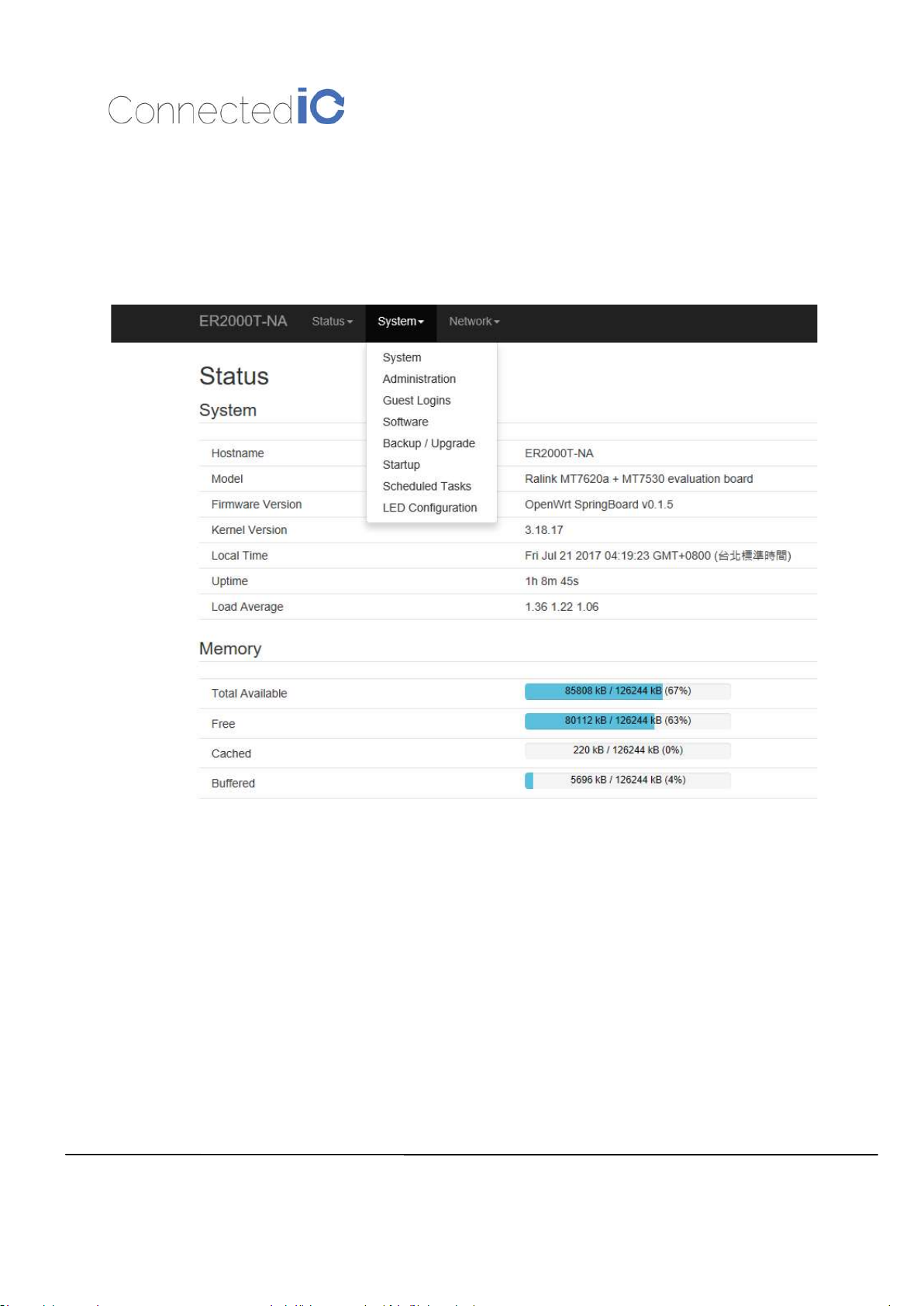
This chapter describes how to back-up the current EMU Router configuration to your computer, and how
to restore that same configuration at a later date if needed. This can be done by selecting System >
Backup/Upgrade:
Figure 10: System List
4.1. Backup the Configuration
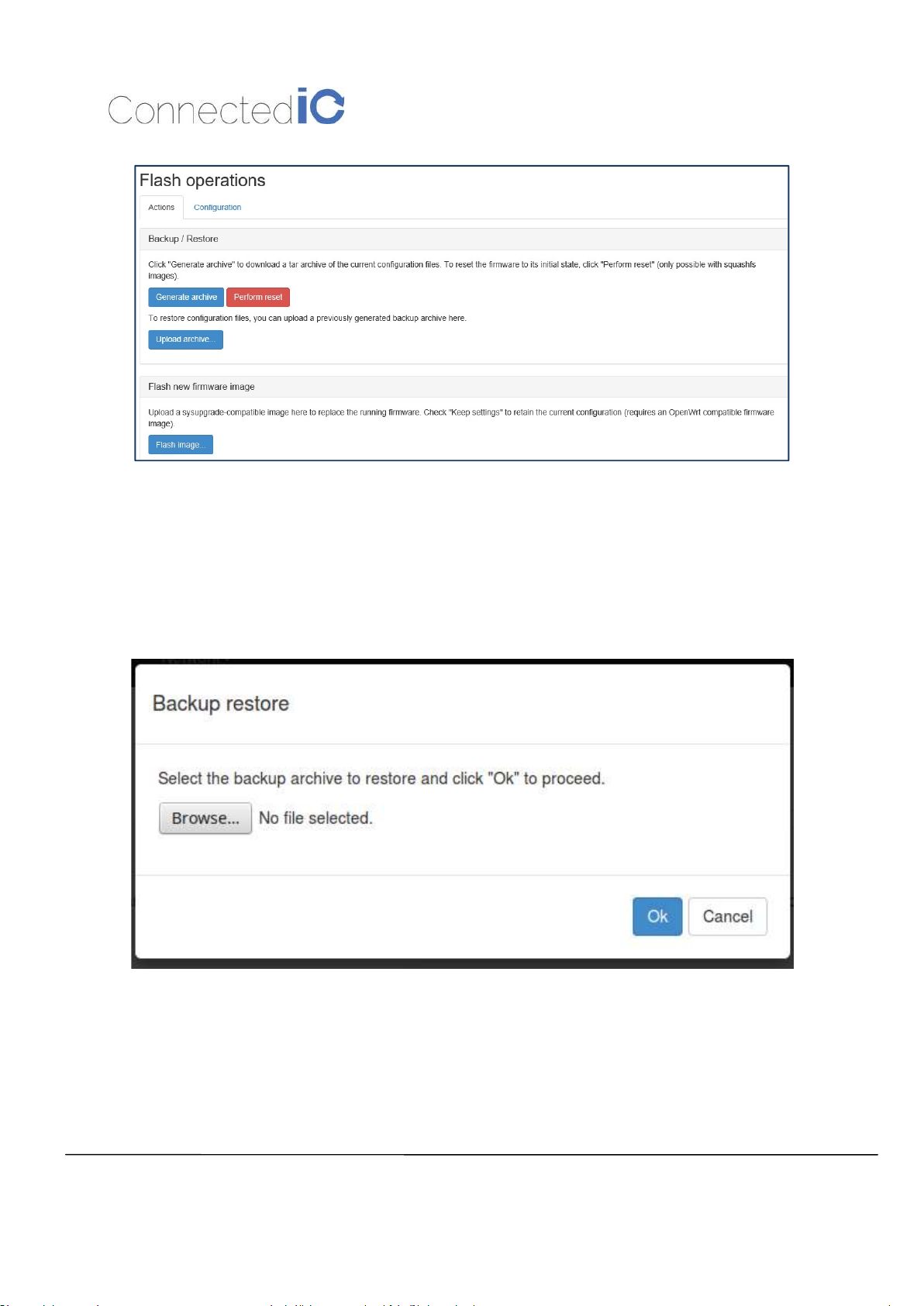
Select Firmware in the GUI page then click the icon “Generate archive” to save this configuration file in
the folder you specified.
Page 14
Connected IO Inc.,
CONFIDENTIAL
14
EMU Router User Manual: ER2000T
-XX-
CAT1
Figure 11: Backup the Configuration
The file is in tar.gz format, we suggest that you can rename it to a meaningful file name.
Revision: 0.6
4.2. Restore the Configuration
Click the icon “Update archive” in flash operations page as shown Figure 8. Device will write the stored
configuration back to flash then reboot the system.
Figure 8: Restore the Configuration
4.3. Reset to Factory Default under Web GUI
Click the icon “Perform reset”, a warning window will pop-up saying “Really reset all changes?” The
device will reset to factory default and reboot if “Yes” is chosen.
NOTE: It is important NOT to power off the device before the entire process is completed.
Page 15
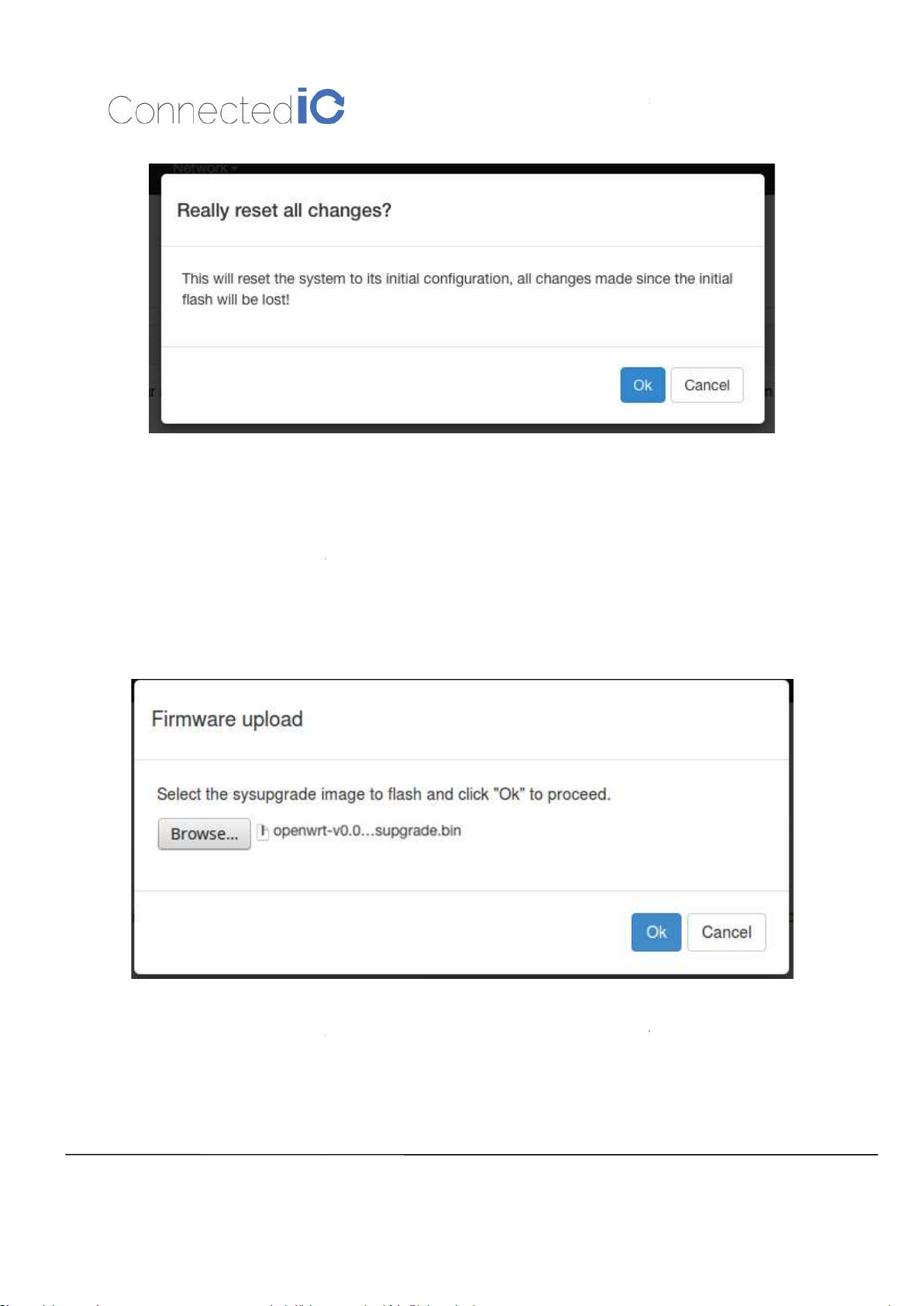
4.4. Firmware Upgrade
from web GUI, and find “
image that you want upgraded to the device.
The upgrade process may take longer than
the device during the process. Administrators can PING the device after the upgrade process is
completed to ensure that the device is programmed and rebooted successfully.
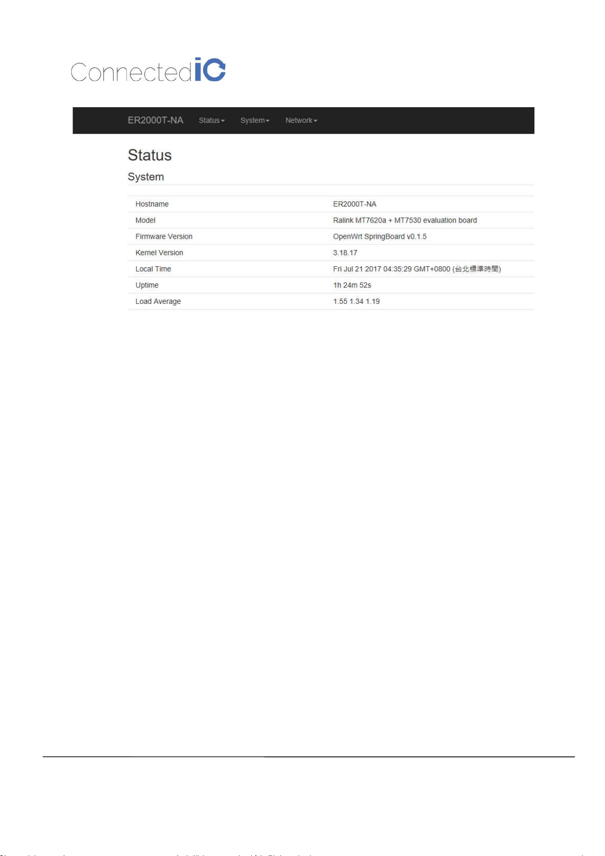
check if the FW version is correct. This can be done by selecting Status
Overview, and find the “Firmware Version” field.
Connected IO Inc.,
CONFIDENTI
A
L
EMU Router User Manual: ER2000T
” section. Click the icon “browse” and select the new
10 minutes for flashing and rebooting. It is important NOT to
15
-XX-
CAT1
Figure 9: Reset to Default
Revision: 0.6
Select System
power off
Flash image
Figure 10: Firmware Upgrade
After upgrading the new FW,
->
Page 16
Connected IO Inc.,
CONFIDENTIAL
16
EMU Router User Manual: ER2000T
-XX-
CAT1
5. Modem
Figure 11: New Firmware Version
Revision: 0.6
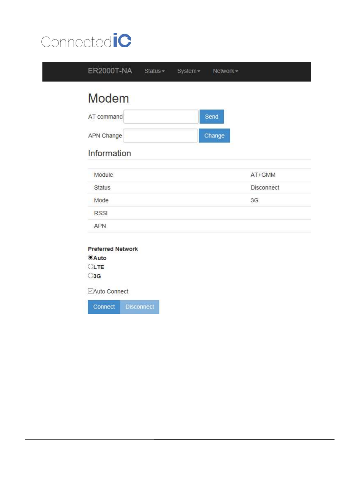
Select Network -> Modem as shown Figure 12.
Page 17
Connected IO Inc.,
CONFIDENTIAL
17
EMU Router User Manual: ER2000T
-XX-
CAT1
Revision: 0.6
Figure 12: Modem Page
5.1. AT Command
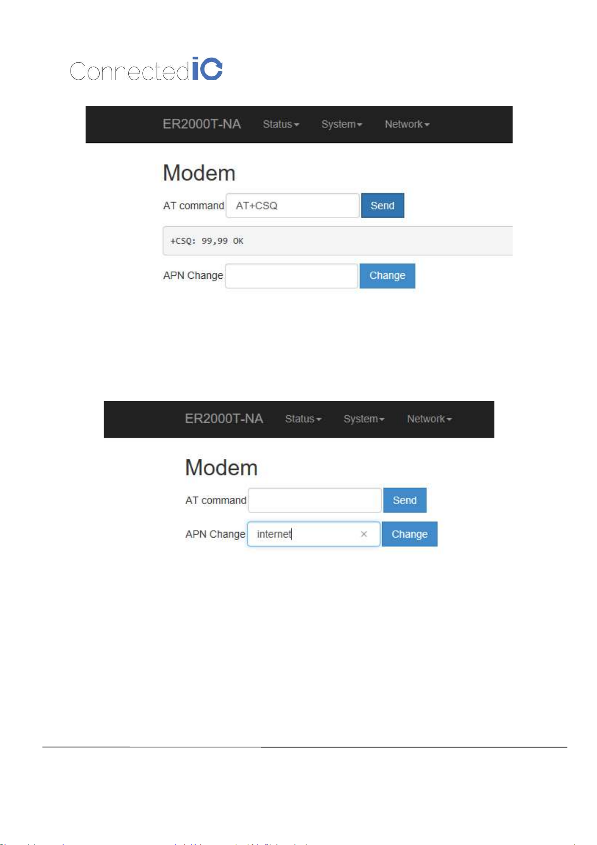
You can use the AT command to check the LTE status. The AT command format is “AT+ Command” for
example: AT+CSQ. Enter the AT command and click “Send”.
AT command responses will be displayed in the message bar right below the command as shown in
Figure 13.
Page 18
Connected IO Inc.,
CONFIDENTIAL
18
EMU Router User Manual: ER2000T
-XX-
CAT1
Figure 13: AT Command Example
Revision: 0.6
5.2. APN Change
Typically, your APN is auto-configured or auto-detected. The APN Change command allows you to
change the local telecommunication company. Enter the APN name and click “Change” button as shown
in Figure 14.
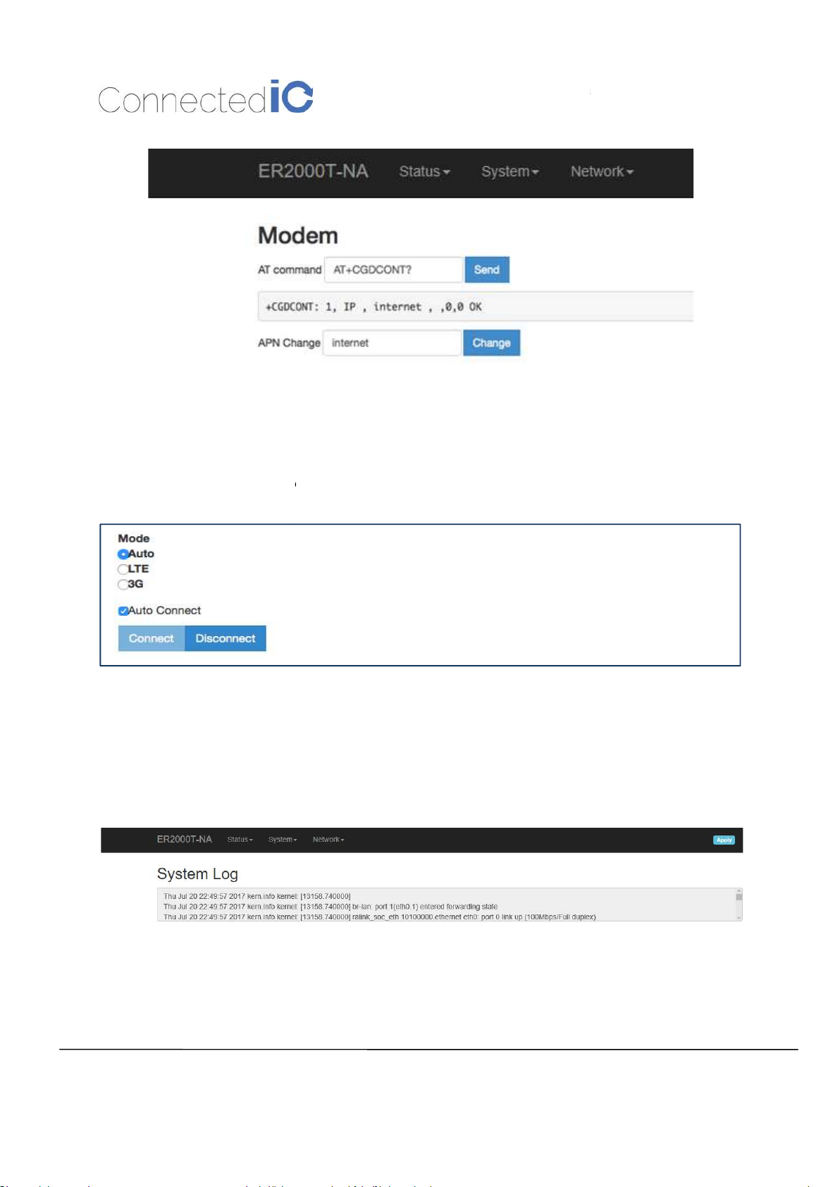
If you would like to check whether the APN setting is successful, pleases enter AT command
“AT+CGDCONT?” See Figure .
Figure 14: APN Change
Page 19
5.3. Mode Setting
the switching between 3G and LTE modes.
for most of the applications. In Auto mode
Connected IO Inc.,
CONFIDENTI
A
L
EMU Router User Manual: ER2000T
that you should choose
ically coordina
19
-XX-
CAT1
Figure 19: Check APN Function
Revision: 0.6
EMU Router supports
Auto mode
different modes.
6. LOG
6.1. System LOG
Select Status -> System Log
the system will automat
Figure 20: Mode Change
We suggest
te between
6.2. Kernel LOG
Select Status -> Kernel Log
Figure 21: System Log
Page 20

Connected IO Inc.,
CONFIDENTIAL
20
EMU Router User Manual: ER2000T
-XX-
CAT1
Figure 15: Kernel Log
Revision: 0.6
7. Antenna
7.1. Detachable Antenna Guidelines
This M2M Router device, ER2000T-NA-CAT1, integrates an LTE (4G) and WiFi radio function. Is uses an
external antenna (dipole antenna) and a standard antenna connector (SMA type) which is not covered
under FCC 15.203 requirements. Therefore, this equipment needs to be installed by a professional
technician since the M2M application usually resides inside other equipment where the end-user cannot
change the external antennas easily.
There is no doubt that the antennas can be replaced by the end-user once installed in the final
configuration.
7.2. Antenna – Installation Guidelines
When installing the antenna to the EMU Router product line there are a number of items to consider so
good antenna performance can be maintained.
Install the antenna in a place covered by the LTE signal.
Antenna must not be installed inside a metal case.
Antenna shall also be installed according to the Antenna manufacturer instructions.
Antenna integration should optimize the Radiation Efficiency. Efficiency values >50% are
recommended on all frequency bands for any antennas selected.
Antenna integration should not dramatically perturb the radiation pattern. It is preferable to get,
after antenna installation, an omnidirectional radiation pattern for the best overall coverage.
Antenna Gain must not exceed values indicated in the regulatory requirements in order to meet
related EIRP limitations.
o Typical antenna Gain in most M2M applications should not exceed 2dBi.
At least 20cm of separation distance between the antennas, the collocated router transmitters, and
the human body must be maintained always.
7.3. Recommended Antennas
Page 21

Connected IO Inc.,
CONFIDENTIAL
21
EMU Router User Manual: ER2000T
-XX-
CAT1
698-960MHz/1710
-
2170MHz/2500
-
To aid in selecting an antenna for this router device the following antennas are recommended as
functional and meeting the requirements for most M2M applications.
Revision: 0.6
No.
1 GTT Europe LTD OA-LTE-01-01-GT Omni-Dipole
Manufacturer Part No.
Antenna
Type
8. Environmental
8.1. Operating Environment
Operating Temperature: -20°C to +55°C
Storage Temperature: -40°C to +85°C
8.2. Physical Parameters
Size: 114.6mm x 99.6mm x 24.7mm
Weight: 157gr.
9. Approvals and Certifications
Peak Gain
2960MHz/2400MHz-2500MHz
0.7 dBi Max / 3.8 dBi Max /3.2 dBi Max/
3.1 dBi Max
9.1. Manufacturing
RoHS Compliance
This device has been tested and found to be RoHS compliant with the council RoHS directive –
2011/65/EU.
9.2. North American Certifications
9.2.1. ER2000T-NA-CAT1
FCC Compliance:
o This device Complies with Part 15 of the FCC Rules. Operation is subject to the
following two conditions. (1) This device may not cause harmful interference, and (2)
this device must accept any interference received, including interference that may cause
undesired operation.
o This device has been tested and found to comply with the limits for a Class B digital
device, pursuant to Part 15 of the FCC Rules.
Page 22

Connected IO Inc.,
CONFIDENTIAL
22
EMU Router User Manual: ER2000T
-XX-
CAT1
Canada
o CAN ICES-3 (B) / NMB-3 (B)
o This device Complies with ICES-003:2016 Issue 6, Class B.
PTCRB Certification
o This device has been tested and conforms to the PTCRB testing standards which confirms
that this cellular product operates within a defined global and industry specification and
meets the minimum level of Network performance required by PTCRB operator Member
networks.
9.2.2. ER2000T-VZ-CAT1
FCC Compliance:
o This device Complies with Part 15 of the FCC Rules. Operation is subject to the
following two conditions. (1) This device may not cause harmful interference, and (2)
this device must accept any interference received, including interference that may cause
Revision: 0.6
undesired operation.
o This device has been tested and found to comply with the limits for a Class B digital
device, pursuant to Part 15 of the FCC Rules.
Canada
o CAN ICES-3 (B) / NMB-3 (B)
o This device Complies with ICES-003:2016 Issue 6, Class B.
Verizon Open Development Certification
9.3. FCC General Warning
This equipment has been tested and found to comply with the limits for a Class B Digital Device,
pursuant to part 15 of the FCC Rules. These limits are designed to provide reasonable protection against
harmful interference in a residential installation. This equipment generates, uses and can radiate radio
frequency energy and, if not installed and used in accordance with the instructions, may cause harmful
interference to radio communications. However, there is no guarantee that interference will not occur in
a particular installation. If this equipment does cause harmful interference to radio or television
reception, which can be determined by turning the equipment off and on, the user is encouraged to try
and correct the interference by one or more of the following measures:
Reorient or relocate the receiving antenna.
Increase the separation between the equipment and the receiver.
Page 23
Connected IO Inc.,
CONFIDENTIAL
23
EMU Router User Manual: ER2000T
-XX-
CAT1
698-960MHz/1710
-
2170MHz/2500
-
Revision: 0.6
Connect the equipment into an outlet on a circuit different from that to which the receiver is
connected.
Consult the dealer or an experienced radio/TV technician for help.
CAUTION:
Any changes or modification no expressly approved by the grantee of the device could void the user’s
authority to operate the equipment.
RF exposure warning
This equipment must be installed and operated in accordance with provided instructions and the
antenna(s) used for this transmitter must be installed to provide a separation distance of at least 20 cm
from all persons and must not be co-located or operating in conjunction with any other antenna or
transmitter. End-users and installers must be provided with antenna installation instructions and
transmitter operating conditions for satisfying RF exposure compliance.
Detachable Antenna:
This M2M Router device, ER2000T-NA-CAT1, integrates an LTE (4G) and WiFi radio function. Is uses an
external antenna (dipole antenna) and a standard antenna connector (SMA type) which is not covered
under FCC 15.203 requirements. Therefore, this equipment needs to be installed by a professional
technician since the M2M application usually resides inside other equipment where the end-user cannot
change the external antennas easily. There is no doubt that the antennas can be replaced by the end-user
once installed in the final configuration.
This radio transmitter FCCID: 2AMRIER2000TNAC1 has been approved by FCC to operate with the
antenna types listed below with the maximum permissible gain and required antenna impedance for each
antenna type indicated. Antenna types not included in this list, having a gain greater than the maximum
gain indicated for that type, are strictly prohibited for use with this device.
No.
Manufacturer Part No.
1 GTT Europe LTD OA-LTE-01-01-GT Omni-Dipole
Antenna
Type
Peak Gain
2960MHz/2400MHz
0.7 dBi Max / 3.8 dBi Max /3.2 dBi Max/
dBi Max
Page 24

Connected IO Inc.,
CONFIDENTIAL
24
EMU Router User Manual: ER2000T
-XX-
CAT1
Revision: 0.6
9.4. Industry Canada (IC) Notices
Canada, Industry Canada (IC) Notices
This device complies with Canada license-exempt RSS standard(s).
Operation is subject to the following two conditions:
(1) this device may not cause interference, and
(2) this device must accept any interference, including interference that may cause undesired
operation of the device.
Canada, avis d'Industry Canada (IC)
Le présent appareil est conforme aux CNR d'Industrie Canada applicables aux appareils radio
exempts de licence. L'exploitation est autorisée aux deux conditions suivantes :
(1) l'appareil ne doit pas produire de brouillage, et
(2) l'utilisateur de l'appareil doit accepter tout brouillage radioélectrique subi, même si le brouillage
est susceptible d'en compromettre le fonctionnement.
Radio Frequency (RF) Exposure Information
The radiated output power of the Wireless Device is below the Industry Canada (IC) radio frequency
exposure limits. The Wireless Device should be used in such a manner such that the potential for
human contact during normal operation is minimized.
This device has also been evaluated and shown compliant with the IC RF Exposure limits under mobile
exposure conditions. (antennas are greater than 20cm from a person's body).
Informations concernant l'exposition aux fréquences radio (RF)
La puissance de sortie émise par l’appareil de sans fil est inférieure à la limite d'exposition aux
fréquences radio d'Industry Canada (IC). Utilisez l’appareil de sans fil de façon à minimiser les contacts
humains lors du fonctionnement normal.
Ce périphérique a également été évalué et démontré conforme aux limites d'exposition aux RF d'IC
dans des conditions d'exposition à des appareils mobiles (antennes sont supérieures à 20 cm à partir du
corps d'une personne).
Detachable Antenna:
This M2M Router device, ER2000T-NA-CAT1, integrates an LTE (4G) and WiFi radio function. Is
uses an external antenna (dipole antenna) and a standard antenna connector (SMA type) which is not
Page 25
Connected IO Inc.,
CONFIDENTIAL
25
EMU Router User Manual: ER2000T
-XX-
CAT1
698-960MHz/1710
-
2170MHz/2500
-
Revision: 0.6
covered under FCC 15.203 requirements. Therefore, this equipment needs to be installed by a
professional technician since the M2M application usually resides inside other equipment where the
end-user cannot change the external antennas easily.
There is no doubt that the antennas can be replaced by the end-user once installed in the final
configuration.
This radio transmitter IC: 22975-ER2000TNAC1 has been approved by Industry Canada to operate
with the antenna types listed below with the maximum permissible gain and required antenna
impedance for each antenna type indicated. Antenna types not included in this list, having a gain
greater than the maximum gain indicated for that type, are strictly prohibited for use with this device.
Cet émetteur radio IC: 22975-ER2000TNAC1a été approuvé par Industrie Canada pour fonctionner
avec les types d'antennes énumérés ci‐dessous avec le gain maximal admissible et impédance
d'antenne requise pour chaque type d'antenne indiqué. Types d'antennes n'est pas inclus dans cette
liste, ayant un gain supérieur au gain maximal indiqué pour ce type, sont strictement interdits pour
une utilisation avec cet appareil.
No.
Manufacturer Part No.
Antenna
Type
1 GTT Europe LTD OA-LTE-01-01-GT Omni-Dipole
========== End of Document =========
Peak Gain
2960MHz/2400MHz-2500MHz
0.7 dBi Max / 3.8 dBi Max /3.2 dBi Max/
3.1 dBi Max
 Loading...