

Page 1
© 2018 Connected IO – All Rights Reserved Worldwide
ConnectedIO™ LTE Router
Quick Installation Guide
Page 2
ER-2000 Quick Installation Guide Page i © 2018 – Connected IO, Inc.
FCC Notice
This equipment has been tested and found to comply with the limits for a Class B digital device, pursuant to Part 15 of the FCC rules. These
limits are designed to provide reasonable protection against harmful interference in a residential installation. This equipment generates, uses,
and can radiate radio frequency energy and, if not installed and used in accordance with the instructions, may cause harmful interference to
radio communications. However, there is no guarantee that interference will not occur in a particular installation. If this equipment does cause
harmful interference to radio or television reception, which can be determined by turning the equipment off and on, the user is encouraged to
try to correct the interference by one of the following measures:
• Reorient or relocate the receiving antenna.
• Increase the separation between the equipment and receiver.
• Connect the equipment into an outlet on a circuit different from that to which the receiver is connected.
• Consult the dealer or an experienced radio/TV technician for help.
FCC ID (LAN): 2AMRIE2000TVZC1
FCC ID (WAN): RI7LE910SVV2
FCC Rule Part(s): 15
Frequency Range: 5.725-5.875 GHz
Equipment Class: Low Power Communication Device Transmitter
Max. Output Power: 50 mW (+17 dB)
This device complies with Part 15 of FCC rules. Operation is subject to the following two conditions: 1) this device may not cause harmful
interference, and 2) this device must accept any interference received, including interference that may cause undesired operation.
FCC regulations require that a person knowledgeable in electronics and trained in the correct installation of this device professionally install
this device. Professional installers have a responsibility to comply with FCC part 15 rules on antenna limits and amplification. Unauthorized
modifications to the device could void the End-user’s authority to operate it.
All interface cables must be shielded.
Page 3
ER-2000 Quick Installation Guide Page ii © 2018 – Connected IO, Inc.
Table of Contents
OVERVIEW ....................................................................................................................................................................................... 1
UNPACKING THE ER2000 UNITS ...................................................................................................................................................... 2
ER2000™ Router Unit (RU) ....................................................................................................................................................... 2
AC Power Adapter ...................................................................................................................................................................... 3
Antennas ...................................................................................................................................................................................... 3
LEDs ........................................................................................................................................................................................... 4
Ports ............................................................................................................................................................................................ 4
Antenna Connectors .................................................................................................................................................................... 4
PLANNING THE INSTALLATION ......................................................................................................................................................... 5
Determining the Location of the LTE Tower............................................................................................................................... 5
Power and PoE Adapters ............................................................................................................................................................ 6
INSTALLING THE ER2000 ................................................................................................................................................................ 7
A Brief Word About Safety .......................................................................................................................................................... 7
Inserting a SIM Card .................................................................................................................................................................. 7
Apply Power to the RU ................................................................................................................................................................ 7
Initial IP Address Setup .............................................................................................................................................................. 8
Attaching to the LTE Network ................................................................................................................................ ..................... 8
Test the link ................................................................................................................................................................................. 8
The instructions in this document have been carefully checked for accuracy and are presumed to be reliable. Connected IO and its writers
assume no responsibility for inaccuracies and reserve the right to modify and revise this document without notice. If you discover an error in
this document, please e-mail your comments or suggested corrections to [email protected]. Manual Revision 1 – P/N xxx-xxx
Page 4
ER-2000 Quick Installation Guide Page 1 © 2018 – Connected IO, Inc.
Overview
1. For a fast, successful installation, make sure you have:
• A non-switched electrical outlet to power.
• Access to an Ethernet and/or LTE connection.
• A length of CAT-5 or 6 jumper cables to connect Ethernet equipment.
• An activated SIM card. Consult with you your Carrier.
• Any cable tie-down or dressing desired
2. Select a mounting location.
3. Attach the antenna.
4. Install the Power Adapter.
5. Attach any Ethernet cables to the ER2000 RUs and draw the slack cable to the associated Ethernet Equipment.
6. Install and activate the SIM card.
7. Test the link.
FCC regulations require that this device be professionally installed by a person knowledgeable in electronics and
trained in the correct installation of this device.
Page 5
ER-2000 Quick Installation Guide Page 2 © 2018 – Connected IO, Inc.
Unpacking the ER2000 units
The ER2000 units come ready to use. To complete the installation, you will need a CAT-5 jumper cable to
connect your network equipment and an activated SIM card from your Carrier. The following components are
included in the ER2000 system:
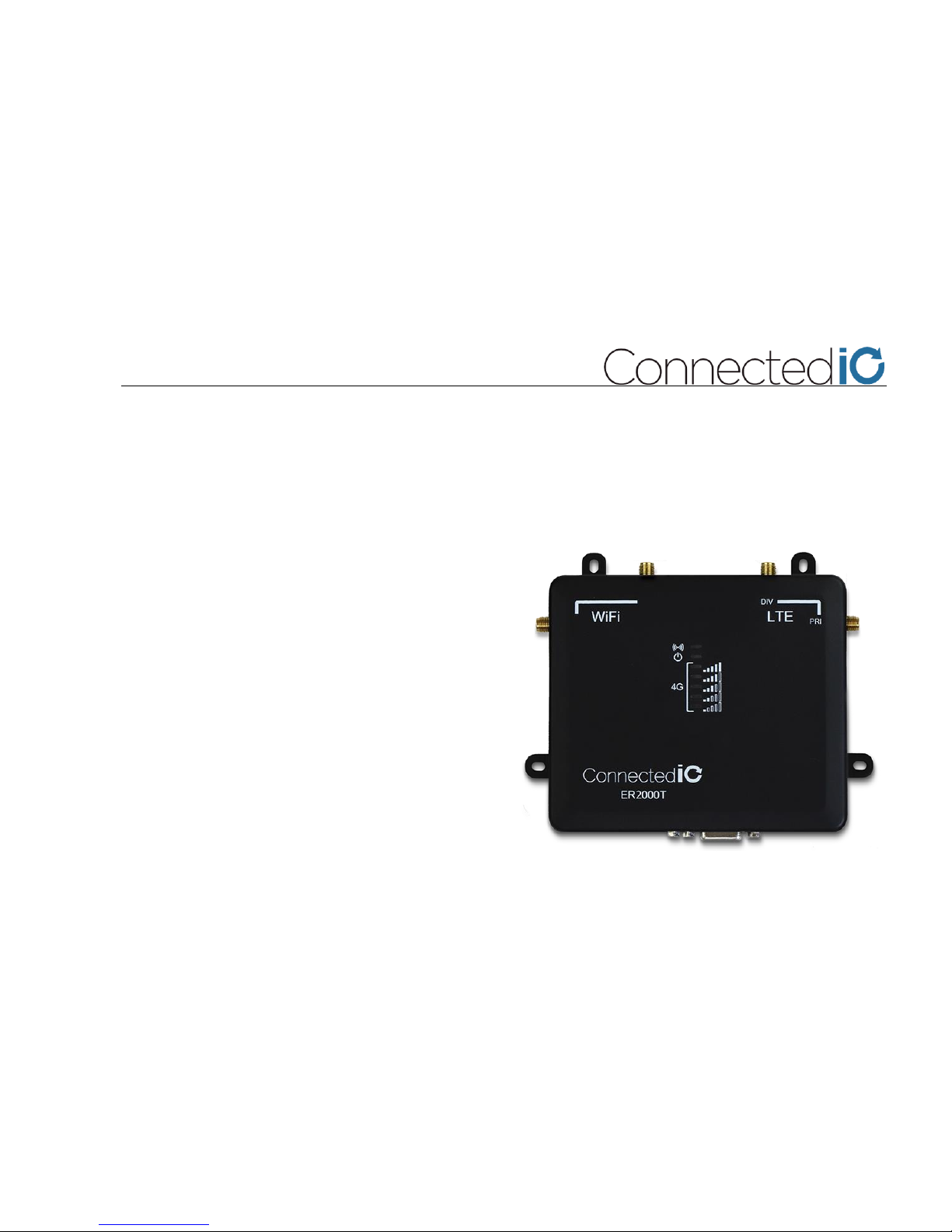
ER2000™ Router Unit (RU)
The RU is the heart of the ER2000 system. Powered
by a 580 MHz MIPS 24K CPU Core, the RU
contains the digital electronics and the transceiver
system, all in one small, power-efficient unit. It routes
traffic between the local connected devices and the
internet through LTE (4G) WAN connections and WiFi
or Ethernet local connections. The WAN Connection is
LTE Category 1 (Release 9), enabling 10Mbps
download speeds and 5Mbps upload speeds. The WiFi
LAN operates in the license-free, 2.4 GHz ISM band
and supports 802.11 B/G/N standards.
Page 6
ER-2000 Quick Installation Guide Page 3 © 2018 – Connected IO, Inc.
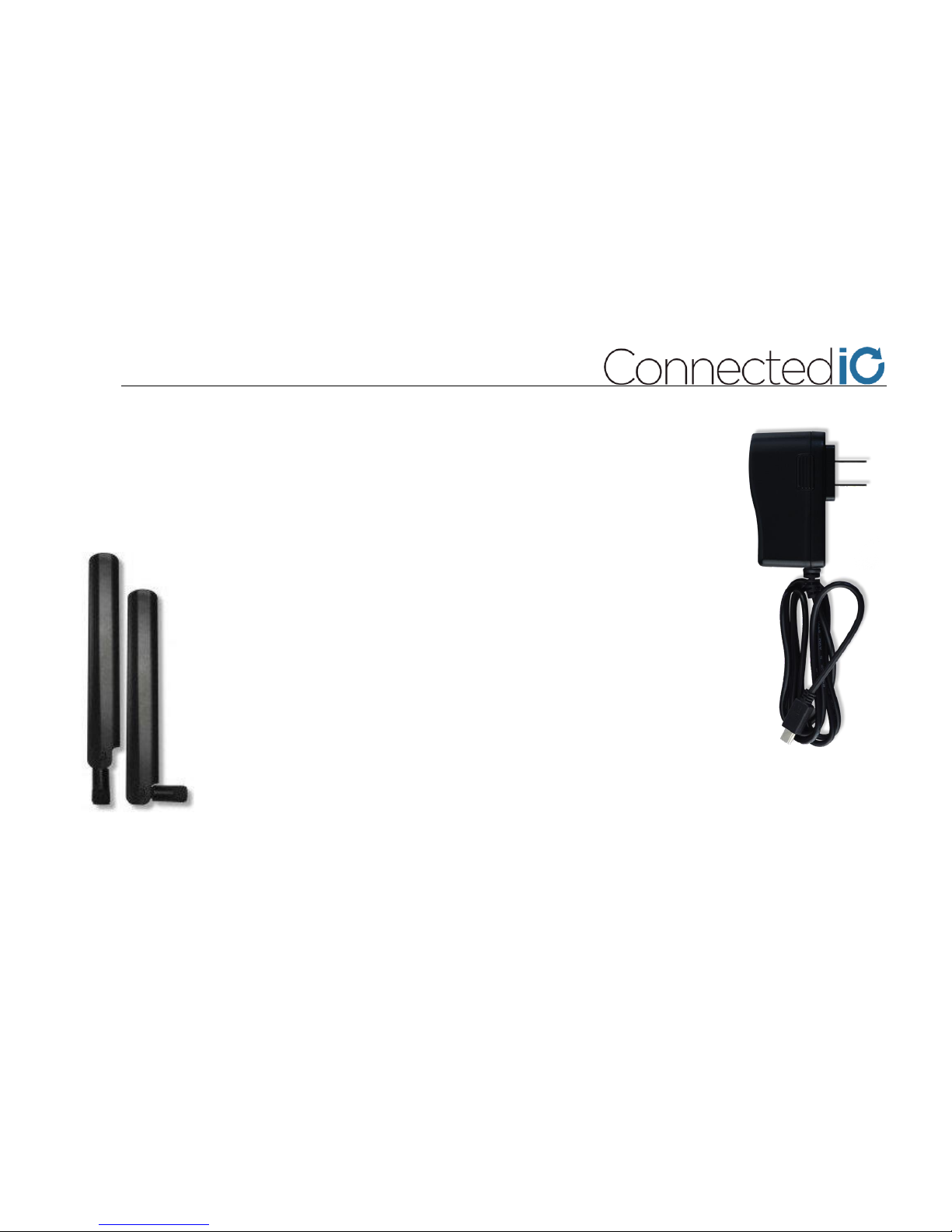
AC Power Adapter
The supplied power adapter provides an easy connection to standard AC electrical
outlets. The adapter plugs into the RU barrel-jack and provides 12 VDC @ 2A of power.
We recommend that you use only the AC Power transformer supplied with the ER2000
unit, or contact Connected IO for a suitable replacement power adapter.
Antennas
Each ER2000 comes with four (4) Omni-Directional antennas. Antennas should
be installed on the unit before it is powered up. For applications with low
bandwidth requirements or in areas with solid 4G coverage, one antenna
(primary) many be sufficient. For all other applications, two antennas (primary
and secondary) are required.
Page 7
ER-2000 Quick Installation Guide Page 4 © 2018 – Connected IO, Inc.
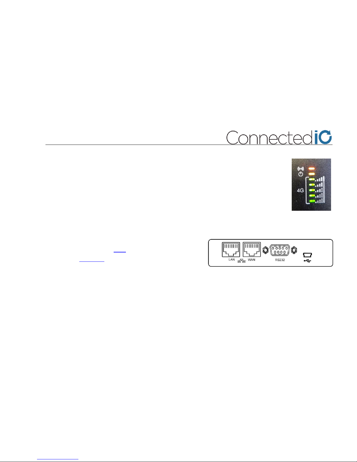
LEDs
On the top panel of the RU are a set of 7 LEDs.
• The first shows Amber if there is a WiFi connection.
• The second shows yellow if the RU is powered on.
• The next 5 LEDs are green and show the LTE Signal Strength.
Ports
The RU has the following port configuration:
• Two 10/100BASE-T Ethernet ports (RJ-45 connectors)
• One RS-232 (DB-9) port with configurable GPIO
• One mini-USB 2.0 OTG connector; 0.5A power
• One 2FF UICC card slot
Antenna Connectors
The RU has 4 SMA antenna connecters, two for the LTE WAN and two for the WiFi LAN. Any included antenna
can attach to any SMA connector on the RU. You MUST attach an antenna to the primary antenna port, labelled
PRI on the top of the RU. The diversity antenna, labelled DIV, can be excluded, but it will give you better overall
LTE performance in environments with weaker coverage. If the RU shows 5 bars with just the PRI antenna
connected, then you can confidently choose to not use the DIV antenna.
Page 8
ER-2000 Quick Installation Guide Page 5 © 2018 – Connected IO, Inc.
Planning the Installation
Proper selection of the installation site is important for performance, safety, and aesthetics. In this topic we will
look at the factors that go into a proper site selection.
Determining the Location of the LTE Tower
To maximize performance, you need to choose a location that is accessible to the LTE tower, Ethernet network
components, and connected devices. It is important to verify that you do not exceed the distance capabilities of
the ER2000. If you are unsure of the distance between the two points, you can use a measuring device such as
range finders. You can also look at the architect’s site plan or contact a local surveying service for assistance.
For LTE, it’s as simple as looking at the signal strength LEDs on the RU. 4-5 bars indicates an acceptable signal
and, therefore, an acceptable mounting location. If this location is fixed and above objects moving in the
environment, is should be a satisfactory.
For Ethernet and Ethernet-enabled connected devices, you must be within 300 feet, cable-wise, of the RU.
For WiFi, a smartphone with a WiFi signal Strength meter can tell you about the performance at a given location
in the environment relative to the ER2000 RU.
Mounting the RU high up on a wall will tend to improve the wireless performance, while mounting it under a
metal desk will detract. In certain cases where the RU cannot be mounted in an ideal location, an external, highgain antenna can be used that overcomes performance limitations. Please contact your Connected IO
representative to learn more.
Page 9
ER-2000 Quick Installation Guide Page 6 © 2018 – Connected IO, Inc.
Power and PoE Adapters
If the location of the BPU is not close to a Power Outlet, you can use an extension cord or a PoE adapter kit to
extend your connection. Before selecting an electrical outlet for use in powering the PoE Adapter, verify that the
electrical outlet is non-switched (not attached to a wall switch).
Page 10
ER-2000 Quick Installation Guide Page 7 © 2018 – Connected IO, Inc.
Installing the ER2000
A Brief Word About Safety
If you chose to mount the antenna high up on a wall, make sure to use the appropriate type of ladder.
Follow ladder safety tips provided by the manufacturer. Connected IO recommends that you have a
partner available to secure the ladder and to offer assistance. Connected IO recommends that you not
mount the unit during stormy weather, on windy days, or anywhere near electrical cables.
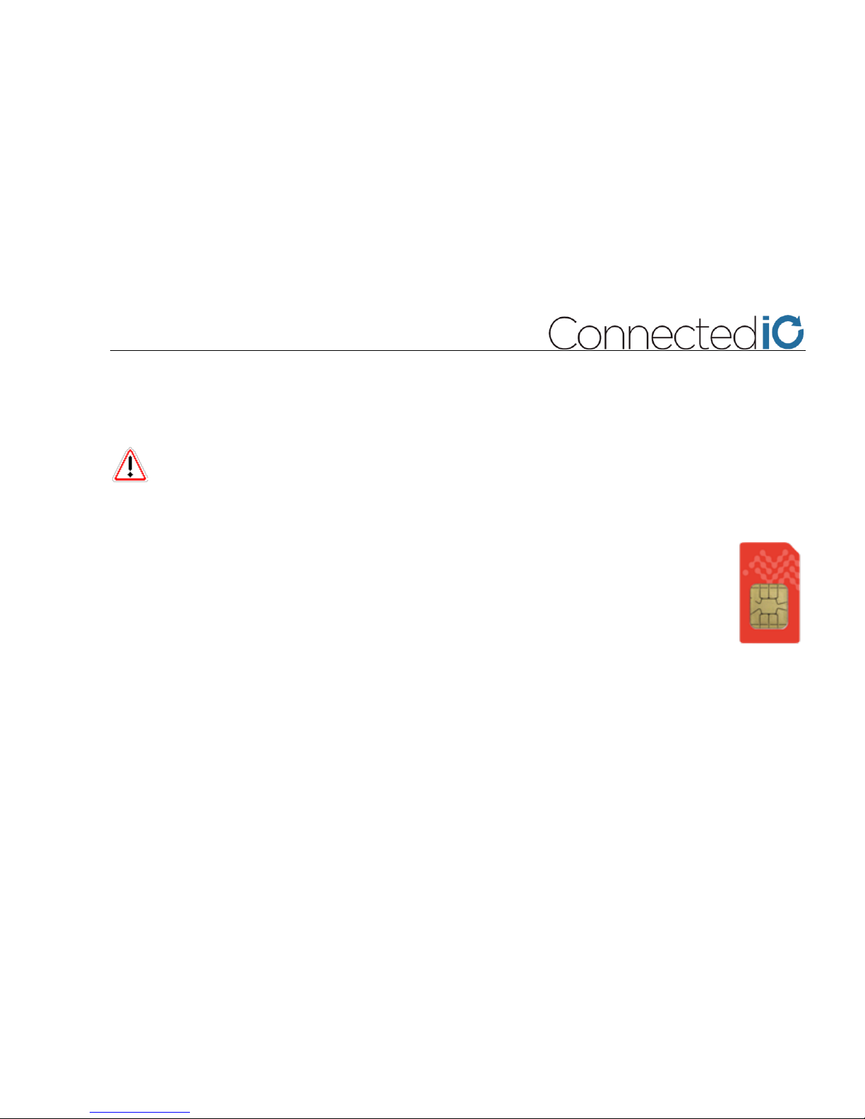
Inserting a SIM Card
Every Connected IO device needs a SIM card to operate in the LTE domain. It is possible to operate
an ER2000 without a SIM card only when using it as an Ethernet-connected router. The ER2000
uses a Mini (2FF) size SIM card which is installed in a slot un the underside of the RU.
Obtain an LTE SIM with an active data plan from your cellular account manager or dealer sales
representative. If requested during activation, the IMEI or the MEID for the device can be found on
the product label.
Insert the SIM notch-end first, gold side down into the SIM slot of the RU. You should hear it click into place.
Apply Power to the RU
Connect the Power Adapter to the RU and plug it into the wall outlet. If the RU is properly powered, the POWER
(2nd) LED will illuminate green, and the LED on the Ethernet jack will illuminate as well.
Page 11
ER-2000 Quick Installation Guide Page 8 © 2018 – Connected IO, Inc.
Initial IP Address Setup
All ER2000 units can be initially accessed on a TCP/IP network with the following parameters:
• IP Address: 192.168.71.1
• Username: root
• Password: password
It is essential that you change the username and password to fit your organization. Leaving it at the default
settings exposes your link to hackers and data theft.
Attaching to the LTE Network
Obtain an LTE SIM with an active data plan from your cellular account manager or sales representative. If
requested during activation, the IMEI or the MEID for the device can be found on the product label.
Insert the SIM notch-end first, gold side down into the SIM slot of the RU. You should hear it click into place.
Test the link
The final step is to ping a known address on one side of the bridge from a station on the other side using the
Windows “Ping” utility. If the ping is done successfully, you have properly installed the ER2000. It should provide
you with years of trouble-free service.
Page 12
ER-2000 Quick Installation Guide Page 9 © 2018 – Connected IO, Inc.
Connected IO
8304 Esters Boulevard
Suite 850
Irving, TX 75063
Main: +1 (972) 366-0070
Toll Free: (888) 366-1657
www.Connected IO.com
 Loading...