

Page 1
CM-RGB25 and CM-RGB26
RCA and BNC
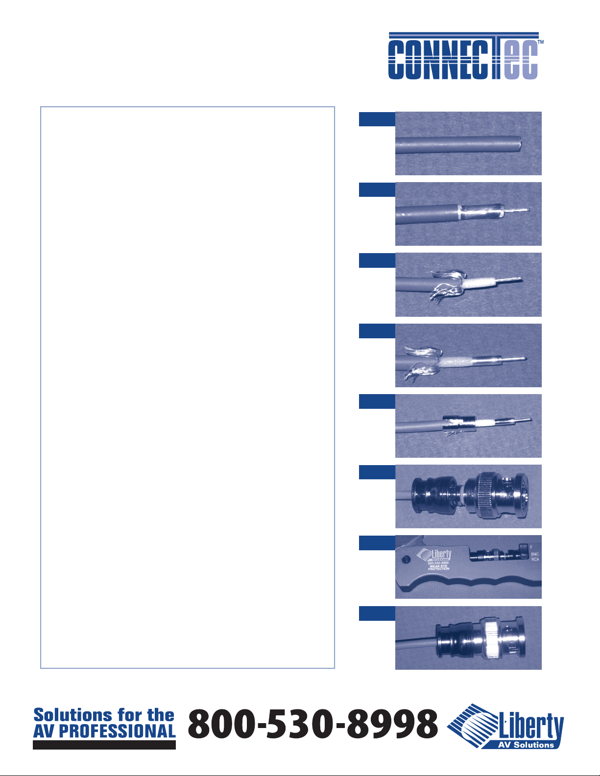
Installation Instructions
Step 1.
Cut o the cable square and ensure the cable is round. The
roundness of the cable can be restored by gently squeezing the
cable between thumb and forenger after cutting. The stripping
tool will function properly with a round cable but may require some
additional trimming if the cable is not round.
Step 2.
of ¼” exposed braid and 4mm exposed center conductor. The center
conductor can be between 4mm (.157”) and 1/4” in length. Do not
use the tool to pull o the slugs, open the tool and remove it from
the cable and use ngers to remove the slugs. If the foil remains
remove it at this time. DO NOT disturb the center conductor.
Step 3.
Fold the braid back against the coaxial jacket. Ensure no braid
strands are wrapped around the center conductor or are loose. Trim
as required to remove any oending strands. The hole at the front of
the pin holder can be used to fan out the shield.
Step 4.
Apply the pin to the center conductor. Hold the cable vertically
and gently drop the pin holder with pin over the center conductor.
Do not push this on as the conductor stranding will birdcage. Spin
the pin holder and thread the pin all the way down against the
dielectric. Once seated rmly pull the pin holder o.
Step 5.
Apply the CSR (Compression Support Ring) over the pin and over
the folded braid. Firmly press down to allow a minimum of .20”
exposed dielectric
Step 1
Step 2
Step 3
Step 4
Step 5
Step 6.
Insert the assembly into the rear of the connector body until the
CSR is visible in the connector sight window. The pin will seat with
a slight click.
Step 7.
Insert the connector into the tool with the appropriate die side
selected (RCA/BNC). Keep gentle pressure on the cable when the
connector is in the tool and fully compress the tool. The connector
will exhibit a two stage crimp action during compression.
Step 8.
Open the tool and remove the connector. Inspect the connector
and gently pull to ensure adequate capture. The termination is
complete. The connector can be coded by utilizing the CM-R-color
rings in the slot located on the rear of the connector body.
www.libertycable.com
11675 Ridgeline Drive Colorado Springs, CO 80921 USA
Step 6
Step 7
Step 8
 Loading...