

Conifer II Ultraflex, 18T-2127, QD-2450, 26T-2127 Installation & Operator's Manual

CONIFER
II
®
WIRELESS TELECOMMUNICATION TECHNOLOGY
Warning: Installation of Antenna near
power lines is dangerous!
Type certified for operation under Part 21.909.
Ultraflex® System Must Be Professionally Installed.
Ultraflex® System
Transverter
Installation & Operator Manual
Photo shows Transverter installed with 18dBi
Microceptor, Model QD-2450. Optional 18dBi
(Model 18T-2127) and 24dBi (Model 26T-
2127) available.
Page 12.
Ultraflex® Two-Way System
Packing List
(1) Response Antenna
Options
•QD-2450
•18T-2127
•26T-2127
(1) Transverter
(1) Power Supply/Inserter
(1) GPS Antenna
(2) Transverter Mounting Brackets
#726055 for inch pipe
#726044 for 1-2 inch O.D. pipe
(2) “L” Bolts #163155.2
Response Antenna Options
QD-2450
(2) #6 x 1/2” Stainless Screws
Model 26T-2127
FEED BOX
(1) Feed assembly
(1) Sub-reflector
(1) #6 x 1/2” stainless screw
(2) Stainless 1/4 x 20 hex nuts
(2) Stainless lock washers
(2) Stainless carriage bolts
REFLECTOR BOX
(2) Reflector halves
(2) Stainless U-bolts
(2) Mast clamps
(1) Mounting "L" shaped bracket
(4) Keps nuts
(4) #8-32 machine screws
(6) Stainless 1/4 x 20 hex nuts
(6) Stainless lock washers
(2) Stainless carriage bolts
(1) Stainless flat plate washer
Model 18T-2127
FEED BOX
(1) Feed assembly
(1) Sub-reflector
(1) #6 x 1/2" stainless screw
(2) Stainless 1/4 x 20 x 1" carriage bolts
(2) Stainless 1/4 x 20 Hex nuts
(2) Stainless 1/4" lock washers
REFLECTOR BOX
(1) Reflector
(1) Mast clamp
(1) Mounting "L" shaped bracket
(1) Stainless U-bolt 1/4 x 20 x 2"
(2) Stainless 1/4 x 20 Hex nuts
(2) Stainless 1/4" lock washers
(1) Stainless flat plate washer
#1
#2
#3
Page 2.
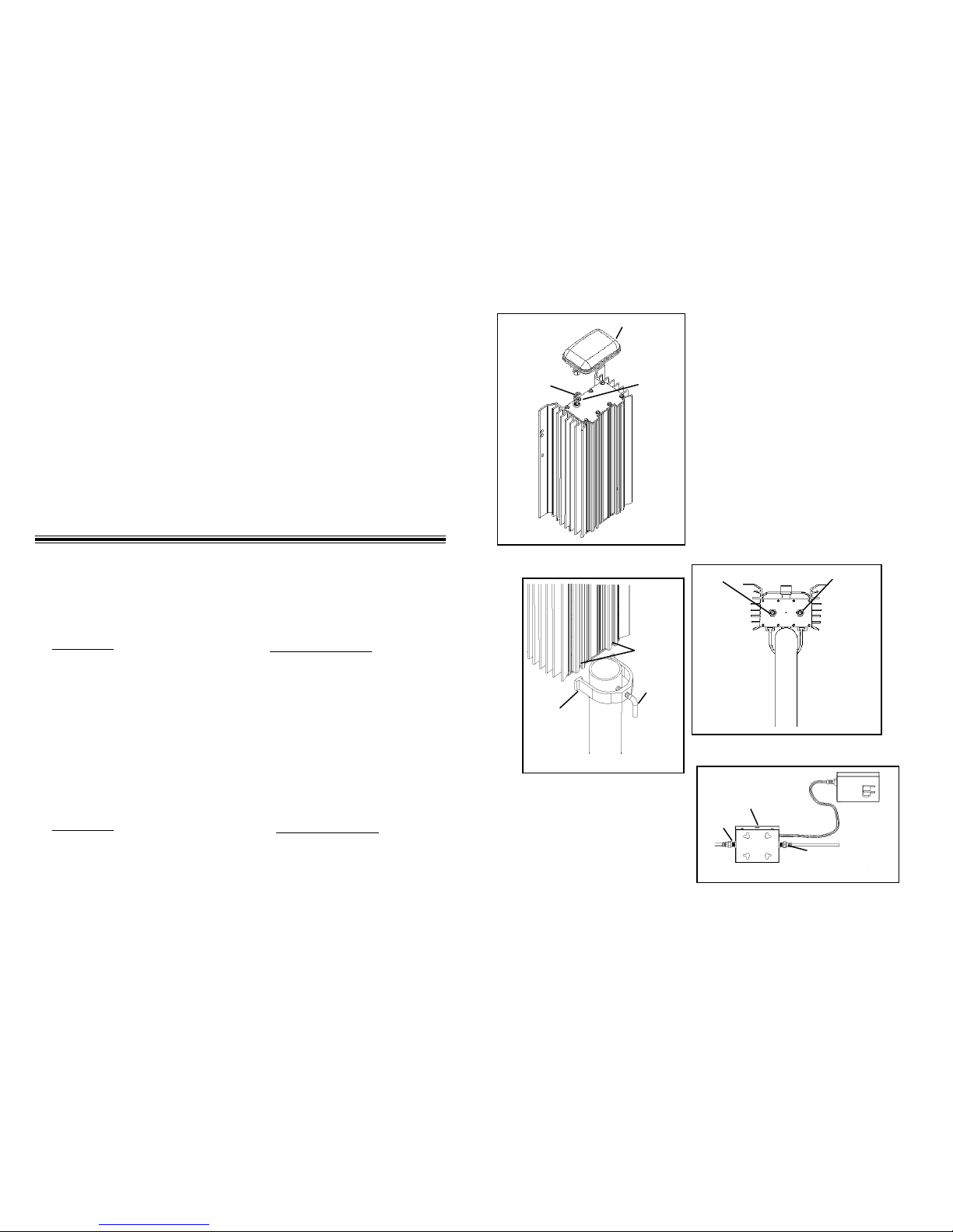
GPS Antenna
GPS Port
Antenna Port
(located on side
of transverter)
Mounting
Bracket
“L” Bolt
Figure 10
Bracket
Chan-
nels
Input/Output
-20dB Test
Figure 9
0-20 dB
Attn.
Downstream
To “Ant”
To “Set”
Figure 11
Figure 8
11. Connect the downlead cable
to the input/output on the
Transverter. (See Figure
9.)
Page 11.
10. Mount the Transverter on the
mast by sliding the mounting
bracketsand “L” Bolts into the
bracket channels on the
backside of the Transverter.
(See Figure 10.)
12. Run the downlead to
the PS-0200 power supply
connector labeled “To
Ant”. (See Figure 11.)
13. Run a cable from the
PS-0200 power supply
connector labeled “To
Set” to the set-top.
(See Figure 11.)
 Loading...