

Page 1
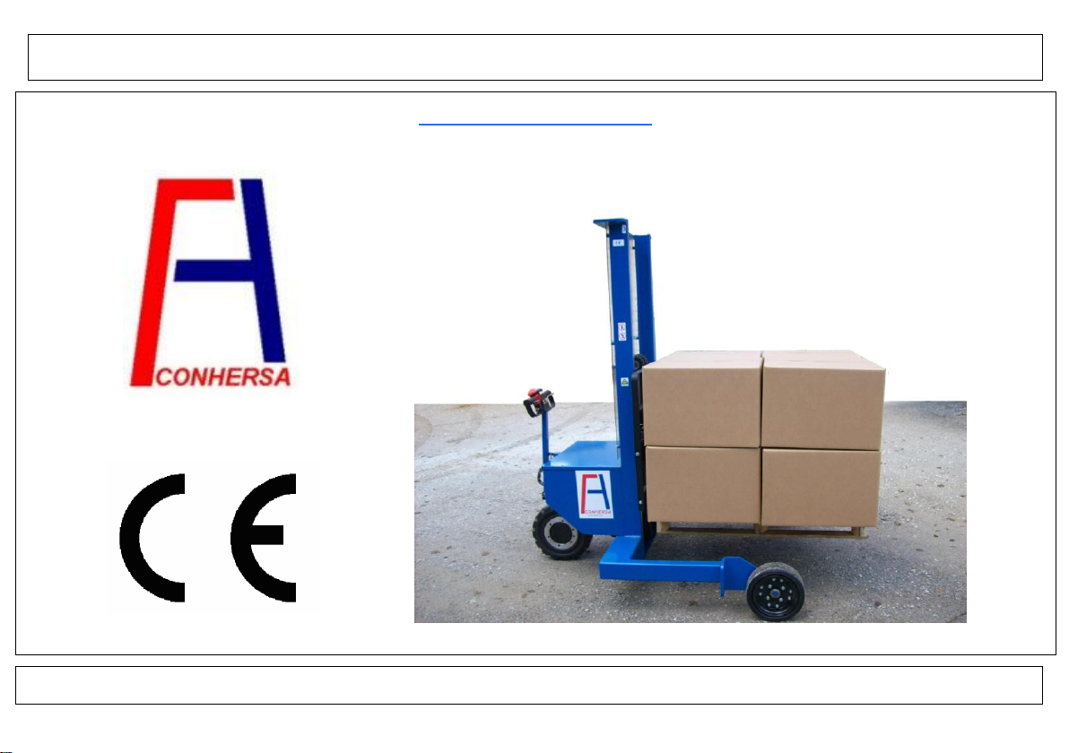
ALL-TERRAIN ELECTRIC LIFTER ET-1000
USER’S MANUAL
Edition: December 2009
Page 2

USER’S MANUAL
INDEX
1. MAIN COMPONENTS 1.1
2. SAFETY INSTRUCTIONS 2.1
3. CONTROL SWITCHES AND INDICATORS 3.1
4. SWITCH ON AND WORK 4.1
5. LOADING AND UNLOADING 5.1
6. SERVICE AND CARE 6.1
7. LONG WAREHOUSING 7.1
8. TECHNICAL SPECIFICATIONS 8.1
2008 CONHERSA
Page 3
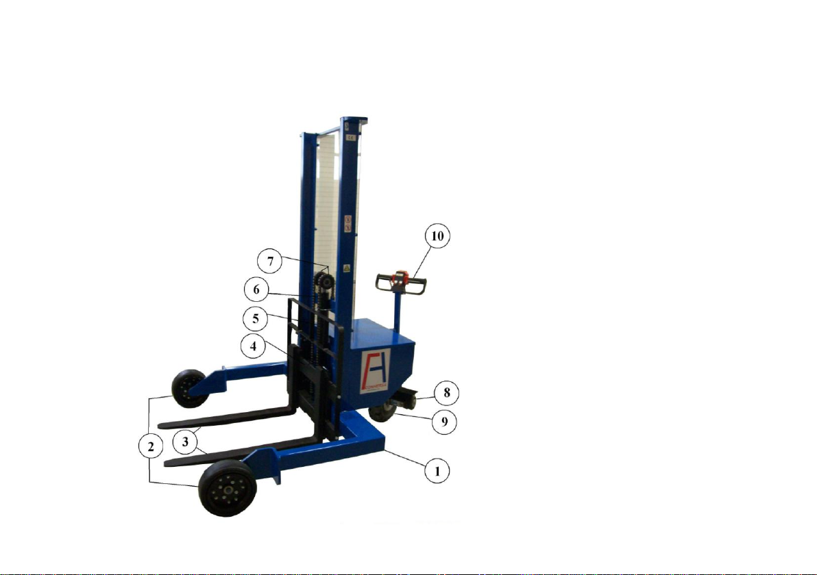
1. MAIN COMPONENTS
1. Chassis
2. Front wheels
3. Fork Grouping
4. Fence
5. Hydraulic Cylinder
6. Chains
7. Pulley
8. Electric braking
9. Motor drive wheel
10. Handle
1.1
Page 4
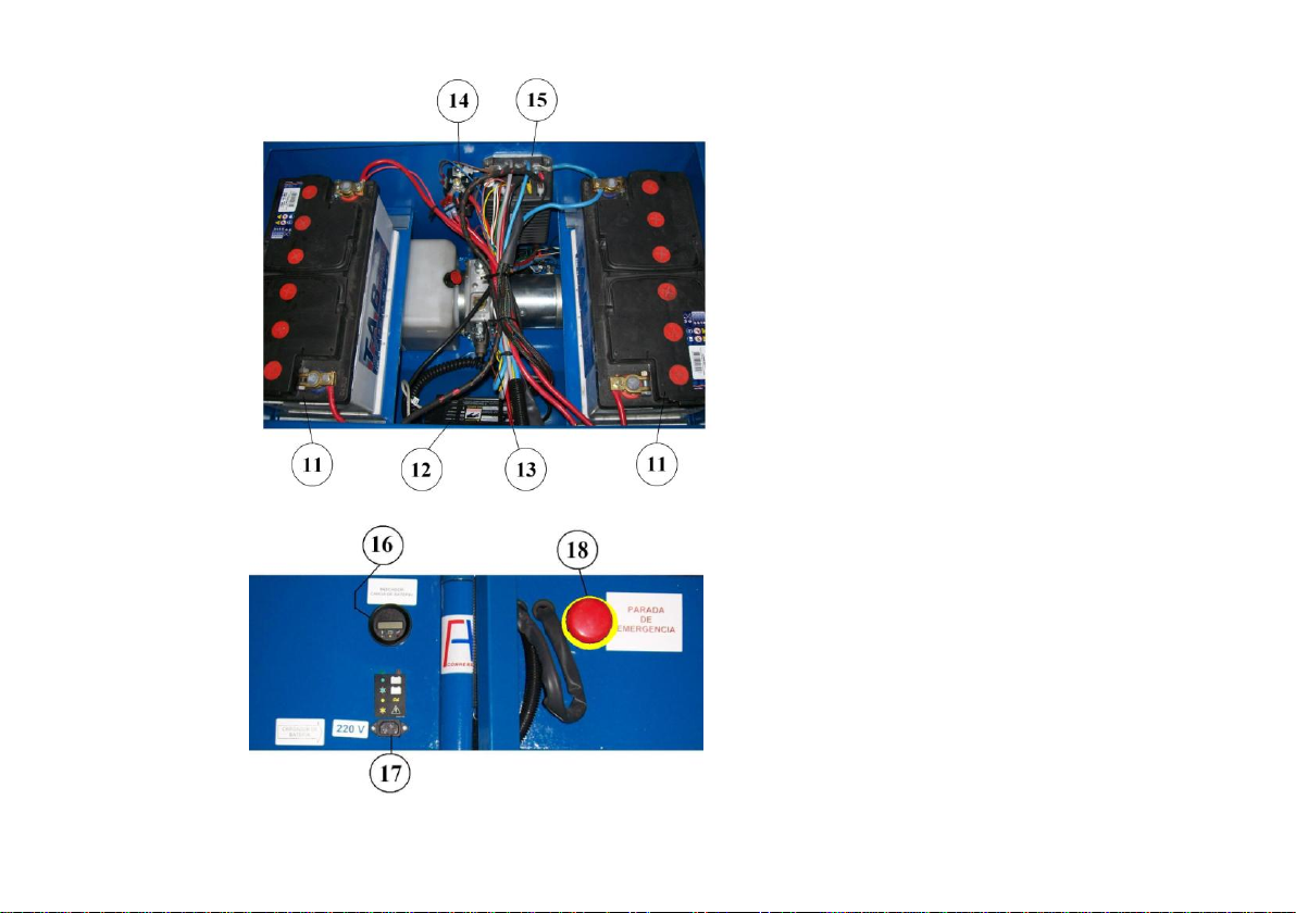
11. Batteries
12. Batteries charger
13. Hydraulic pump
14. Main contactor
15. Electronic controller
16. Load indicator
17. Plug
18. Emergency stop
1.2
Page 5

Page 6

2. SAFETY INSTRUCTIONS
Etiquettes 2.2
All-terrain lifter: safety 2.4
Daily inspections 2.5
All-terrain lifter operator 2.9
Movement in ramps and special areas 2.10
All-terrain lifter transportation 2.12
Testing 2.13
Noise level 2.13
Dangerous environment 2.13
2.1
Page 7
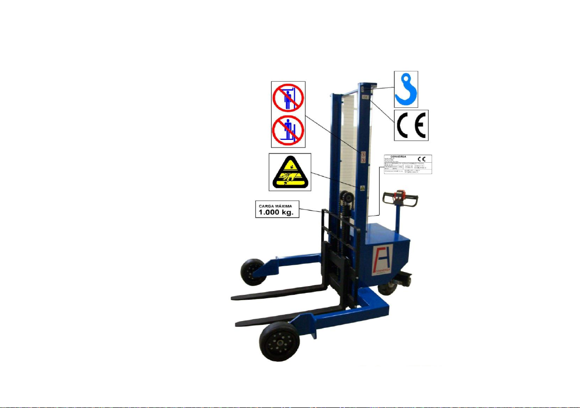
ETIQUETTES
2.2
Page 8
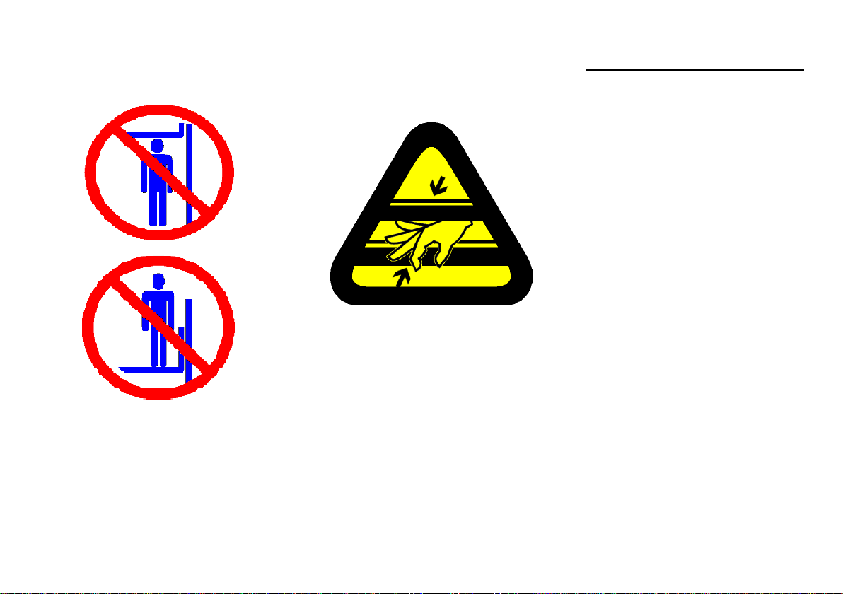
WARNING
WARNING
Keep hands, feet and body
away from masts and forks.
Danger of trapping betwee fix
and mobile parts.
CAUTIONS WHILE CHARGING
BATTERIES
1. Charge batteries at an open-air
area, away from flames, fumes
and sparks. Batteries’ gasses
may be explosives
2. Do not smoke around the
charging area.
3. Do not disconnect the
connector during the process of
charging. Danger of sparks.
Do not stand on nor under the
forks.
2.3
Page 9
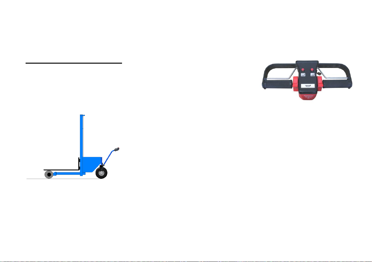
ALL-TERRAIN LIFTER:
SAFETY
USE UNDER INSTRUCTIONS
The All-terrain Lifter may only be
used under instructions included
in this manual.
WARNING
This Lifter may only be used to
transport and placement of
charges and palletised
materials, as per the
instructions of this Manual.
WARNING
Should you wish to use it for
different purposes, you may
ask for CONHERSA’S
agreement and, if necessary,
your local authorities in order
to avoid risks.
WARNING
In case of malfunction, switch
off and contact our technical
service.
2.4
Page 10

DAILY INSPECTIONS
Befote using, following
inspections shall be followed:
1. Brake: When releasing handle,
make sure that the machine is
restrained and you can not
move it.
2. Forks: Visual inspection. Verify
correct lift and descent. No
damage in forks.
3. Hydraulic circuit: Verify possible
looses (leaks) in pipe and
cylinder.
4. Wheels: Verify tyres state.
Tigthen bolts. Verify wheels
pressure.
6. Bettery: Correct battery charge
level: >20%.
7. Horn: check..
8. Lifting: With forks unloaded,
verify correct lifting and
descent.
9. Travel: Pressing the deathman, verify correct movement
forward and reverse.
10. Visual inspection of chains
and pulleys. Verify unloaded
that the stress is equal in both
chains.
WARNING
In case of malfunction, switch
off, inform to whom it may
concerní, and contact the
technical service.
BRAKE
When releasing handle, verify
that speed controller returns to
neutral position and brake is
inmediately actioned. A clicking
sound will be noticed.
Push the Lifter to make sure that
it is well braked and you can not
move it.
5. Control instruments: Switch on
key. Verify batteries’ light
indicatiors lights on.
2.5
Page 11
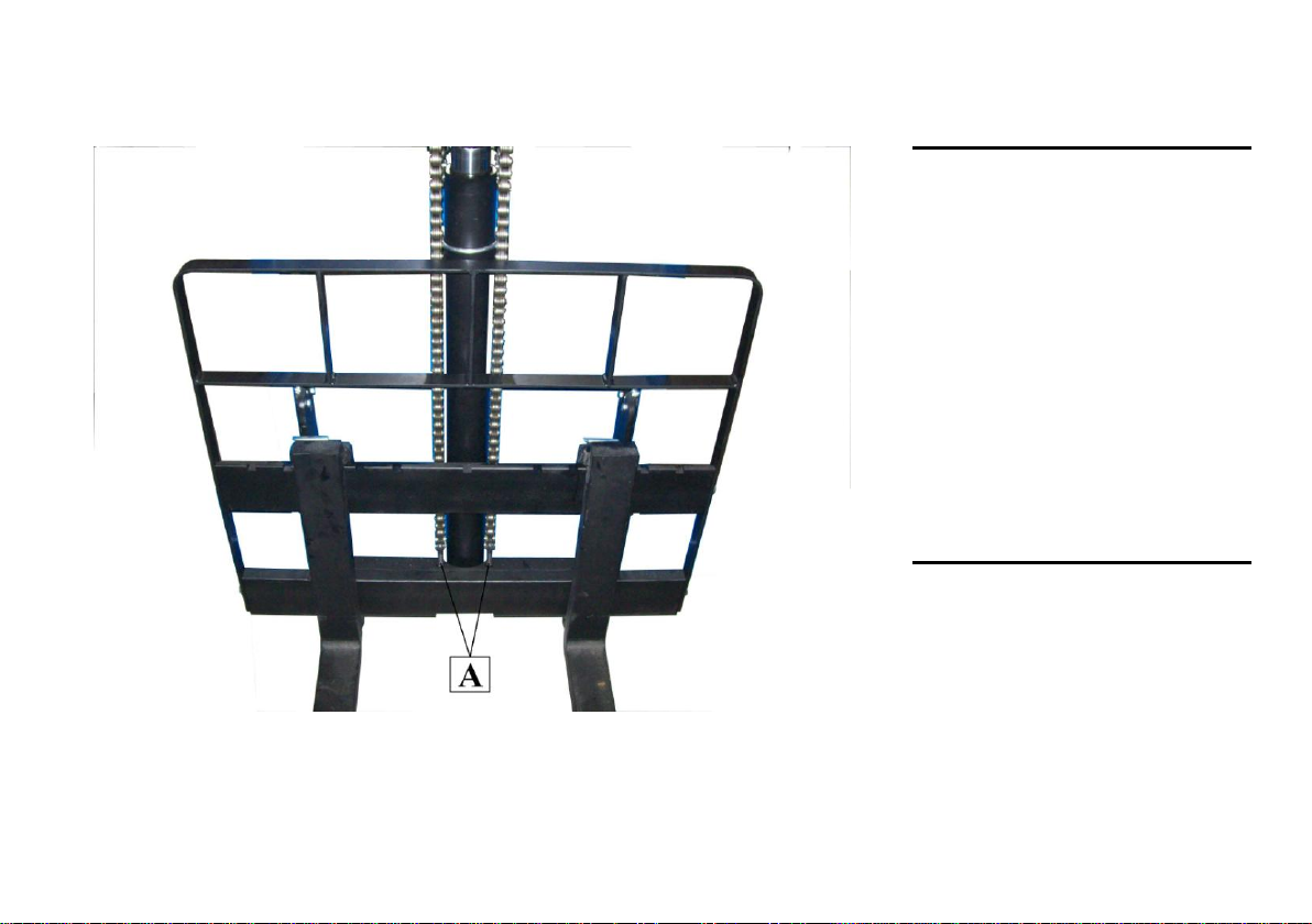
FORKS AND CHAINS
Lift the security bolt by hand. Put
it down back again, and verify
that it stays well placed over the
security fence and can not be
moved unintentionally.
Forks must be placed in
symmetry as per the axe.
To tighten the chains, adjust the
screw placed at the end of the
chains (A) with its bolts.
WARNING
In case of adjusting the chains,
verify that bolts are well tighten
(A)
2.6
Page 12
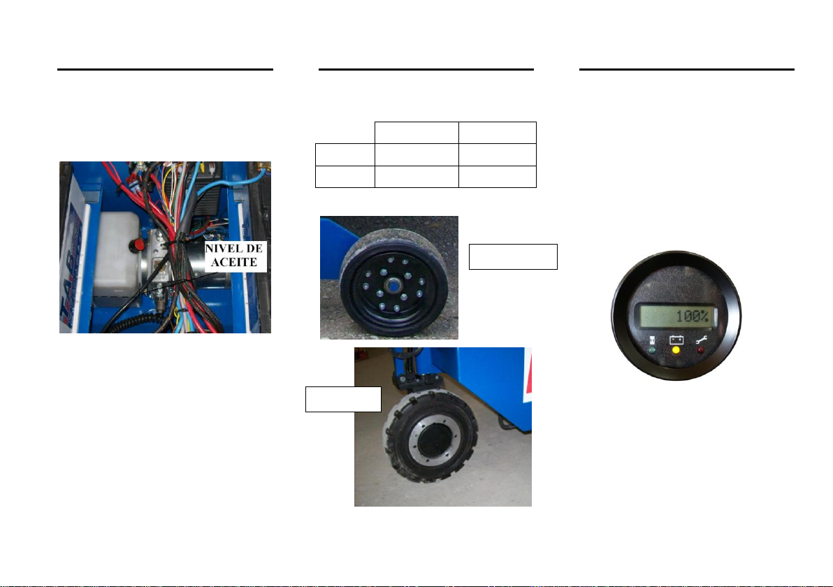
DELANTERAS
TRASERA
Size
3.00-8”
4.00-8”
Solid
Superelastic
Superelastic
front
rear
HYDRAULIC CIRCUIT
RUEDAS
BATTERY CHARGE LEVEL
Verify oil level in the deposit.
Verify in case of possible oil
losses (leaks)
Turn the key to ON position.
Verify charge level in the
indicador. If level is under 20%,
charging is needed.
Charge during approximately 10
hours (See procedure on page
5.1).
2.7
Page 13
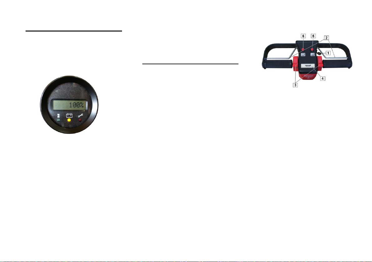
CONTROL INSTRUMENTS AND
CLAXON
Turn on the key. Verify light
indicador i son.
.
HANDLE
Verify correct claxon function
2.8
Unloaded, press lifting button to
verify that forks go up correctly.
Press down button to verify that
forks go down smoothly.
Pressing the death-man system,
turn slighty the hanle to verify that
the blocked brake is self-released
(an audible clicking sound must
be heard), and that the Lifter
comences to move gentil.
Verify both, forward and reverse.
Contact key
Death-man system.
Forward-reverse.
Claxon.
Down-forks button.
Up-forks button.
Page 14
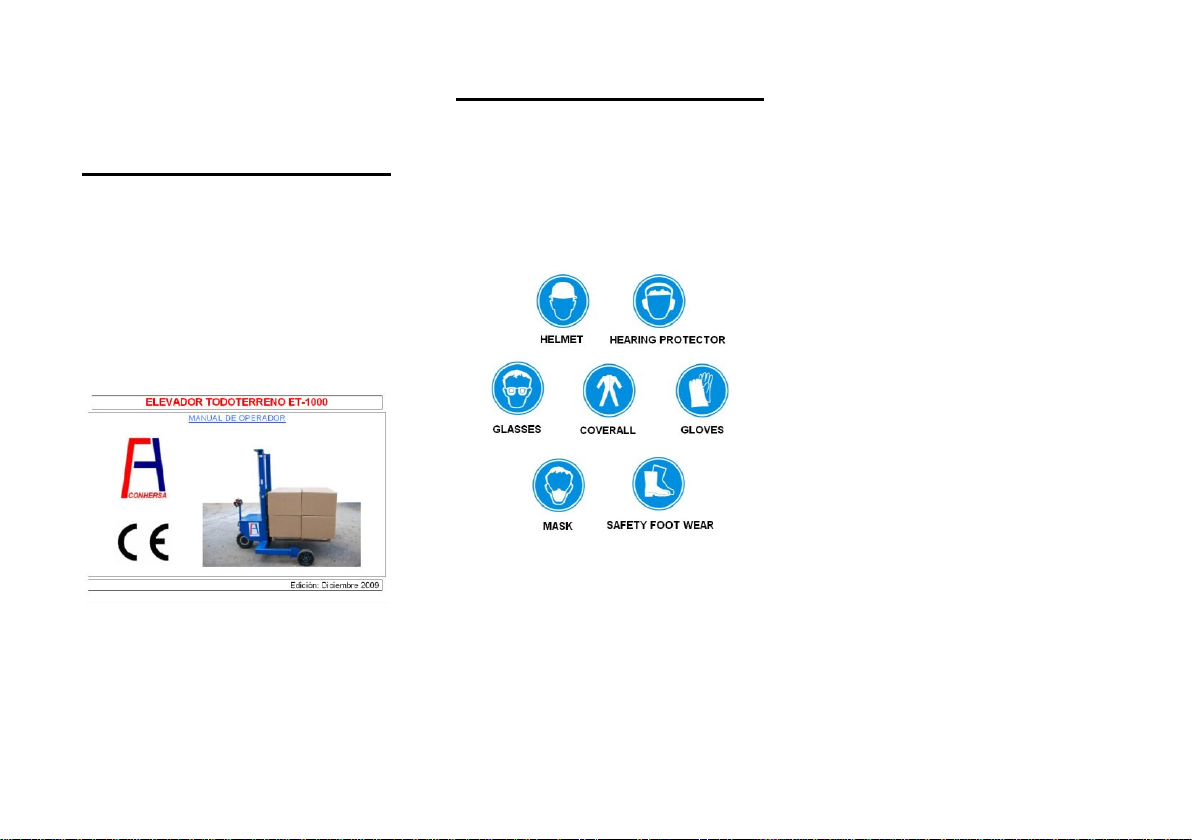
LIFTER OPERATOR
USER’S KNOWLEDGE
WARNING
While using, this manual’s
instructions shall be observed,
as well as local/national legal
dispositions.
SAFETY CLOTHING
Each site’s observations should
also be observed while using the
lifter.
For example:
WARNING
For clothing, observation of the
national rules and obligations
is as must.
Clothes should be tight enough
to avoid traps. If necessary in
the working site, user should
also wear protective glasses,
helmet, gloves, and whatever
required.
2.9
Page 15
MOVEMENT IN RAMPS
AND SPECIAL AREAS
WARNING
Using the lifter et-1000 for
transporting goods in ramps is
strictly forbidden.
Only permitted with the lifter
unloaded, if necessary.
WARNING
Do not turn in ramps.
Movement in ramps is delicate:
pay maximum attention and
care.
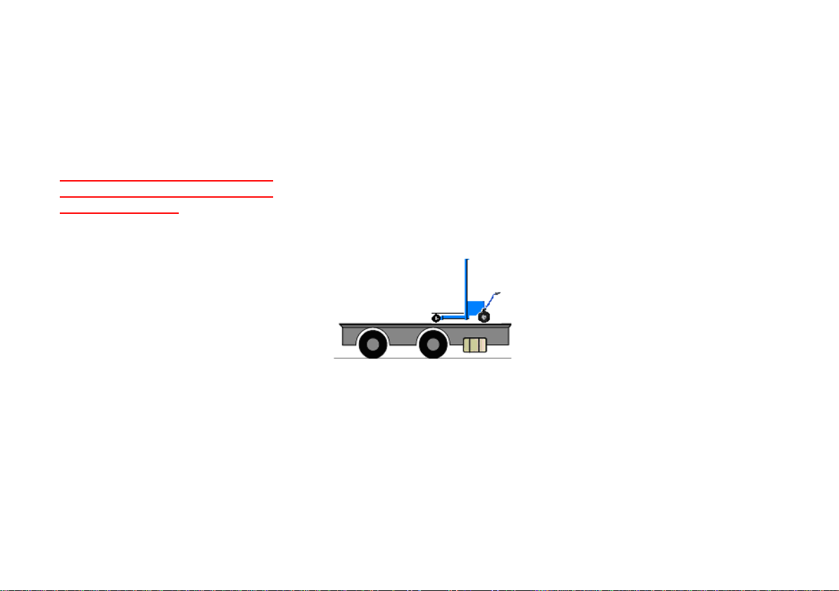
WARNING
Caution when moving on the
truck surface. Please make
sure that the truck is stopped.
Ramp should be firmly placed
on the ground in order to avoid
unexpected movements.
Pay maximum attention during
the loading and unloading of
the lifter on the truck.
2.10
The ramp used to place the
lifter onto the truck must be
resistant enough to bear the
lifter, taking into account the
vertical movement of the lifter.
Page 16
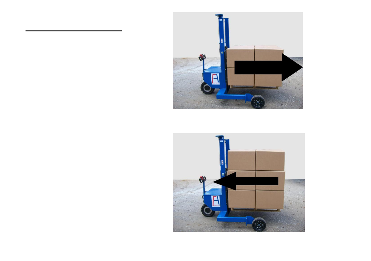
MOVEMENT
Visibility
Do not drive forward when the
load does not permit complete
visibility. In that case, drive
backward, except when driving
into a service lift, where entering
backwards is forbidden.
If visibility difficulties remain,
another operator should indicate
the correct direction. In this case,
drive slowly and handle with care.
Verify that working area is
lightened enough.
2.11
Page 17
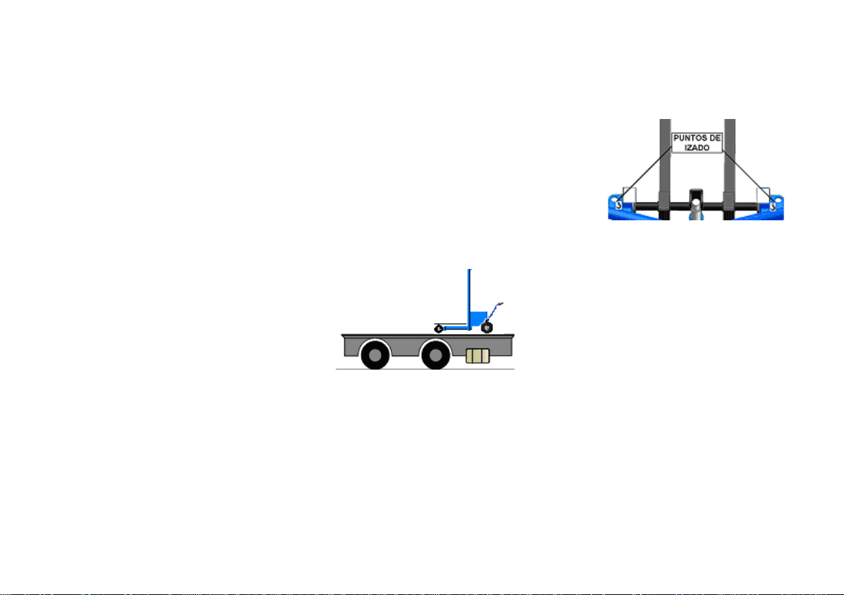
TRANSPORT OF THE
LIFTER
WARNING
1. Unloaded, put forks in the
upper position.
2. Confirm that in and out
angles do not interfere with
the ground or transport
platform.
3. When using a wooden made
bridge between platform and
dock, make sure that the
planks can bear the lifter.
6.Switch off and release
contact key.
4. Use only the lifting hangers
to lift the lifter. (see picture)
2.12
Page 18

NOISE LEVEL
Less than 70 dB (A)
TESTING
After transport or a long
warehousing period, functional
testing is necessary.
Three tests:
1. Daily inspection test. (See page
2.5), to be made by users.
2. Dynamic tests, to be made by
the technical service.
2.1. Movement test.
Confirm that the lifter moves
towards the correct forwardreverse switch, and confirm
that the blocking brake works
properly.
With the lifter loaded, press
up and down buttons to make
sure of correct work.
2.2. Piling test.
2.3. Descending speed test.
Confirm that descending
speed is not more than 0.6
m/s.
3. Hold load test.
With the machine off, fully loaded
with the forks up, confirm that the
forks don’t move down at all, or
they move down but not faster
than 10mm/min.
NOISE LEVEL
DANGEROUS
ENVIRONMENT
WARNING
Use of lifter in dangerous
environment is strictly
forbidden.
A dangerous environment may
cause fire or explosions
because of dust, fumes or
gasses.
Lift completely and descent
the load at maximum speed
several times.
2.13
Page 19
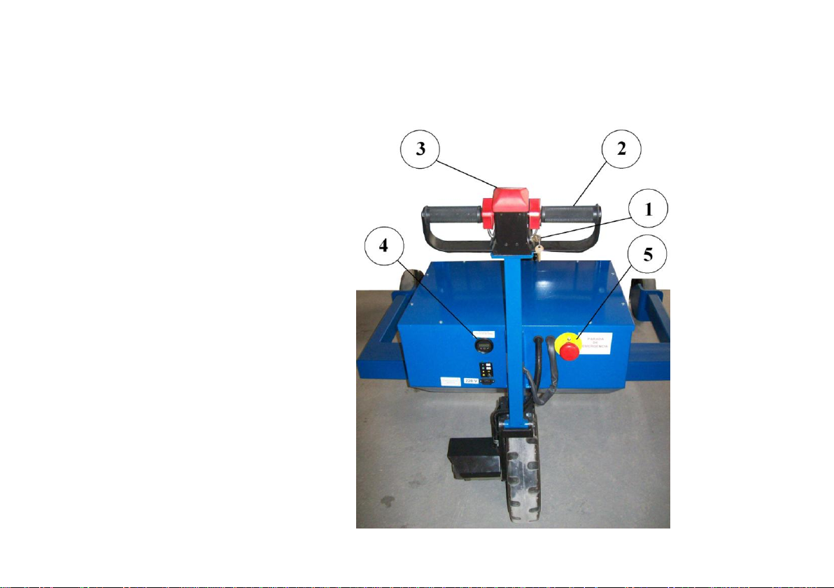
3. CONTROL SWITCHES AND INDICATORS
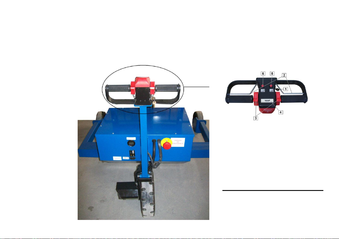
Contact key
Handle
Security anti-trapping button
Battery charge indicator
Emergency stop
3.1
Page 20
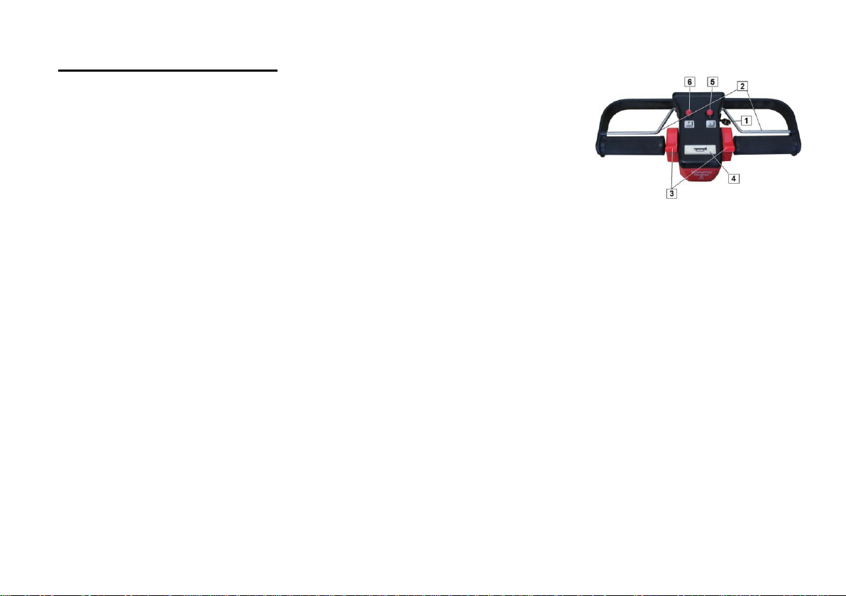
HANDLE SWITCHES
Contact key
Contact key is located at the
lower part of the handle.
It has two positions:
- Connected
- Disconnected
When connected, the batteries
light indicator will turn on.
When disconnected, all circuits
are off.
Forward-reverse switch.
It is the red switch. It may be
pressed either with the left or the
right hand.
When releasing, it comes back to
the neutral position.
Buttons for lifting and descending
the forks.
They are located at the centre of
the handle.
When pressing, the forks start to
move, and they stop just when
buttons are released.
Contact key
Dead-man function
Forward-reverse throttle
Claxon
Forks down button
Dead-man function
Placed at both sides of the
handle. Must be pressed to allow
the machine moving forwardreverse.
3.2
Forks up button
Page 21
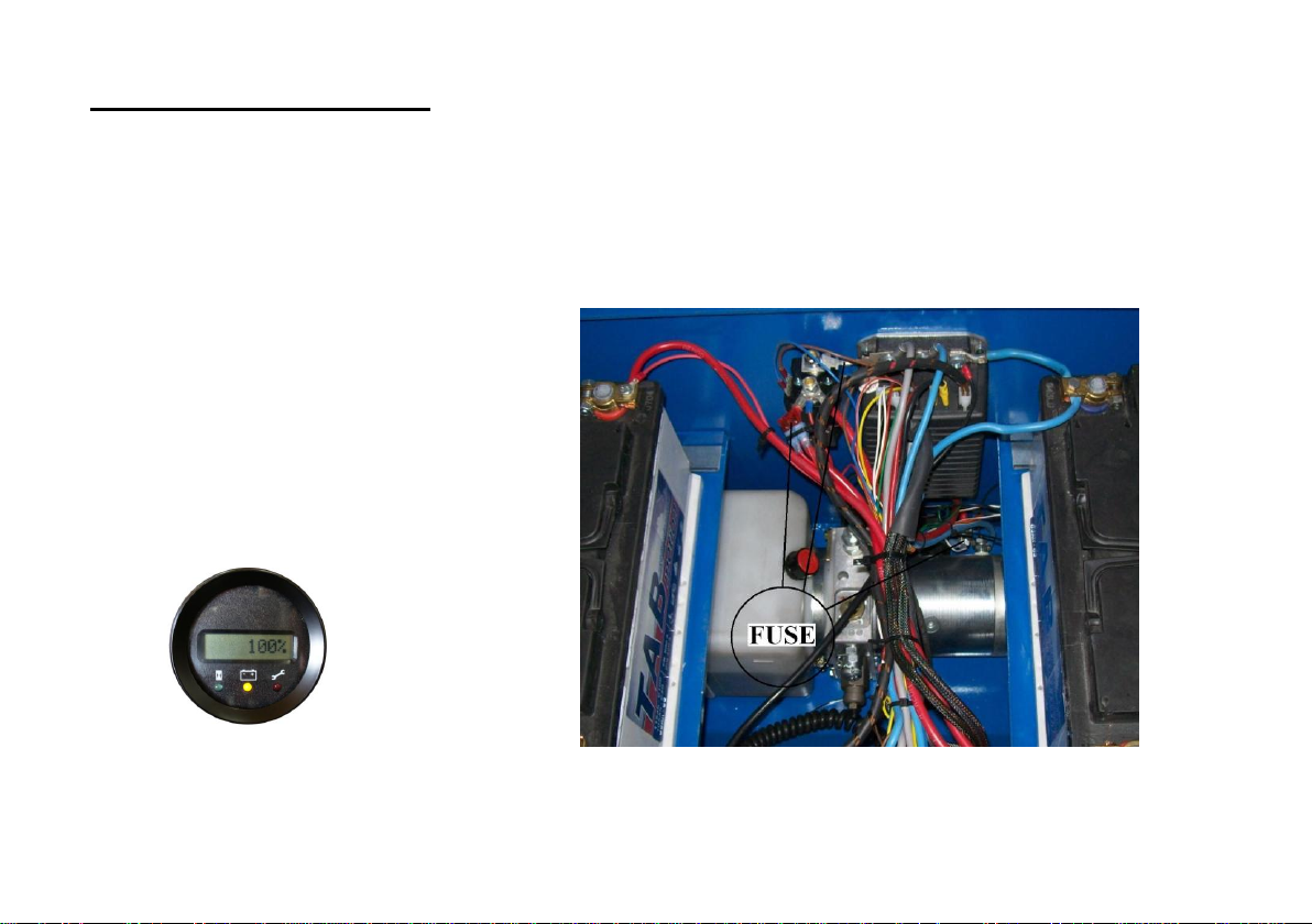
CONTROL INDICATORS
Claxon
Claxon is located next to the up
and down buttons.
Battery charge indicator
It has a display, showing the %
battery level.
Two things to know:
1. When turning the key on, the
display indicates the battery
level.
2. Shows the error code in case of
electronic fault.
Fuses
Te fuses are located in the
electronic controller and in the
hydraulic pump.
WARNING
Fuses should only be replaced
by specialized personnel.
Replace the fuses by similar
ones.
WARNING
When the lifter is not being
used, make sure to turn it off.
3.3
Page 22

Page 23
4.1
4. SWITCH ON AND WORK
Contact key
Dead-man function
Forward-reverse throttle
Claxon
Forks down button
Forks up button
Page 24

SWITCH ON AND WORK
WARNING
Before using the lifter, please
read carefully all the security
instructions of this user’s
manual, pages 2.2 to 2.13 of
this manual.
1. Confirm that the blocking brake
is on by pushing the lifter: you
should not be able to move it.
2. Disconnect the emergency
stop
3. Turn on the key without
pressing the throttle.
5.1
WARNING
If the blocking brake does not
work, do not turn on the key.
4. Make sure that there is enough
battery charge by checking the
indicator.
5. Confirm that your way is clear,
and press the dead-man
function, and the forwardreverse throttle smoothly
towards the required way.
Movement
While moving, the forks must be
at their top position.
Turn
The closer you turn, the slowest
the speed should be, in order to
avoid unexpected load
movements.
Movement on slopes (ramps)
Movement on slopes with the
machine loaded is strictly
forbidden.
WARNING
When leaving the lifter, put
down the forks and remove the
contact key.
If error “CODE 23” appears,
two causes:
1. Forward-reverse throttle has
been pressed without using the
dead-man function, or
2. the temperature thermal switch
of the motor has reached and
excessive heating, due to an
intensive work. Turning off the
machine during 20 minutes
should be enough to cool the
machine.
Page 25

5. LOADING AND
UNLOADING
LOADING
Adjust the forks in symmetry as
per the lifter axe. The more
separated the forks are, the more
stability there is.
Face the load frontally and stop
just before. Adjust forks height to
enter into the pallet to be loaded
correctly.
Move forward smoothly under the
pallet, and when stopping, make
sure that the blocking brake is
automatically activated (blocking
sound should be noticed)
Lift the load. Make sure it remains
stable. Press forward or reverse
and move slowly.
TRANSPORT
Moving with the lifter loaded
should be made with special care
and attention. If the load height
does not allow proper visibility,
the lifter must be driven forward,
except when entering into the
service lifts, where it is strictly
forbidden.
UNLOADING
Move towards the unloading area
slowly.
Verify that, when stopping, the
automatic blocking brake is on
(blocking sound).
Put down the forks to unload.
Move reverse to get away from
the pallet.
When restarting again, make sure
that the forks are in the top
position to avoid any obstacle
while moving.
5.1
Page 26

Page 27

6. SERVICE AND CARE
Classification of maintenance works 6.2
Maintenance to be made by the technical service 6.2
Maintenance to be made by users 6.3
6.1
Page 28

CLASSIFICATION OF
MAINTENANCE WORKS
There are two types of maintenance
works:
1. Technical service: Only to be
made by the technical service.
2. User: To be made by the lifter
users (qualified worker)
WARNING
User should not make any
reparations nor maintenance
when technical service is
required.
Some operations may be
dangerous and should only be
made by the technical service.
MAINTENANCE TO BE MADE
BY THE TECHNICAL
SERVICE
The following operations should
only be made by our technical
service:
1. Batteries condition control.
2. Change batteries.
3. Change hydraulic oil.
4. Adjust motor pump.
5. Maintenance of the electronic
control.
6. Change fuses.
MAINTENANCE TO BE
MADE BY THE USER
As well as the daily inspections (see
page 2.5), the worker must carry on
with the following:
1. Change the front tyres.
2. Charge batteries.
3. Batteries electrolyte level control.
4. Lifter cleaning.
5. Emergency forks descent.
6.2
Page 29
MAINTENANCE TO BE
MADE BY THE USER
WARNING
Before any maintenance, turn
off the key.
Confirm that the automativ
blocking brake is on.
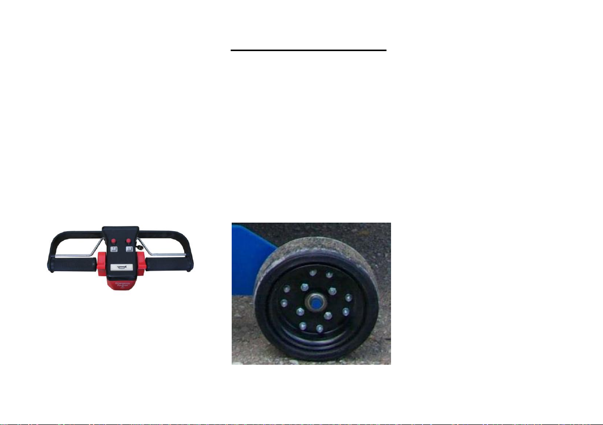
CHANGE FRONT WHEELS
Front wheels
1. Put a wooden chock under the
lifter to separate it from the
floor. Verify that lifter remains
stable
2. Release off the security ring
and take off the wheel.
3. Mounting process is the in
reverse sense. Try not to
damage bolt and ring when
fastening.
6.3
Page 30
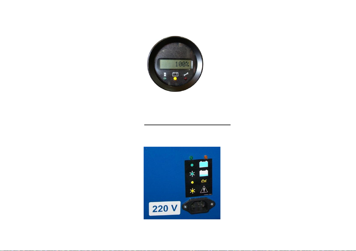
BATTERY CHARGE
WARNING
1. Charge the batteries in a
well ventilated area, away
from heating points and
sparks. (Gases of batteries
may be explosives)
2. Do not smoke in the
charging area.
3. Do not disconnect the
connector during the
charging process: risk of
sparks.
Suggestions for the battery charge
1. For a longer battery life, it
should be discharged at least
35% before charging.
2. To avoid deep discharge that
could cause lifeless, when
arriving to a 20% of battery
charge, the machine slows its
speed drastically.
Charging process
1. Move lifter close to an electric
socket (220 V).
2. Turn off the key.
3. Connect the provided cable
to the lifter and an electric
socket (220 V).
4. Verify that the yellow and
green lights of the left-handside case of the lifter are
lightened.
5. Leave charging cycle to
C
complete while the green light
flickers.
6. Batteries are completely
charged when the green light
is permanent.
7. Disconnect the cable, wind it
and keep it safe. .
8. Turn the contact key on and
confirm that all the battery
charge level is at 100%.
6.5
Page 31
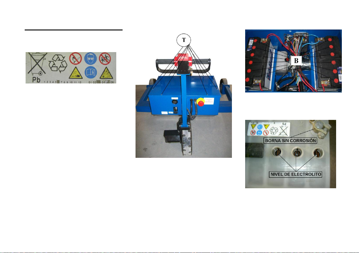
BATTERIES MAINTGENANCE
WARNING
1. Batteries maintenance must be
made by authorized personnel.
2. Always use gloves and
protective glasses.
3. Smoking in the area is
forbidden.
Maintenance frequency
Must be done at least twice a year
(if possible, before and after
summer )
1. Unfasten with a screwdriver the 8
screws (T) and the metal cover.
2. Take out the metal cover.
Batteries should now be seen.
3. Confirm that there are no
electrolyte leaks and no corrosion
on the tips.
4. Put aside the battery glasses
carefully (B), without touching the
connecting tips.
5. Verify that the electrolyte level is
correct. If necessary, fill in with
distilled water up to the nets.
6.5
Page 32
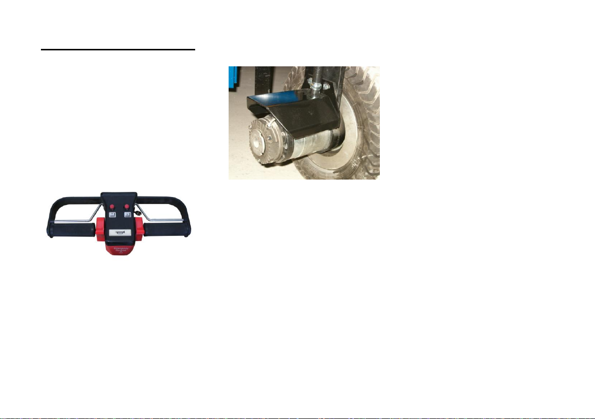
CLEANING THE LIFTER
WARNING
Before cleaning, turn off the
key.
Verify that the blocking brake
is on.
Cleaning the handle.
Clean the dust with a brush.
Do not use water.
Finish with a dry cloth.
Cleaning the motor chassis
Clean the dust with a brush.
Do not use water.
Finish with a dry cloth.
Cleaning the forks grouping
guides.
Clean the dust with a brush.
Do not use water.
Finish with a dry cloth.
6.7
Page 33
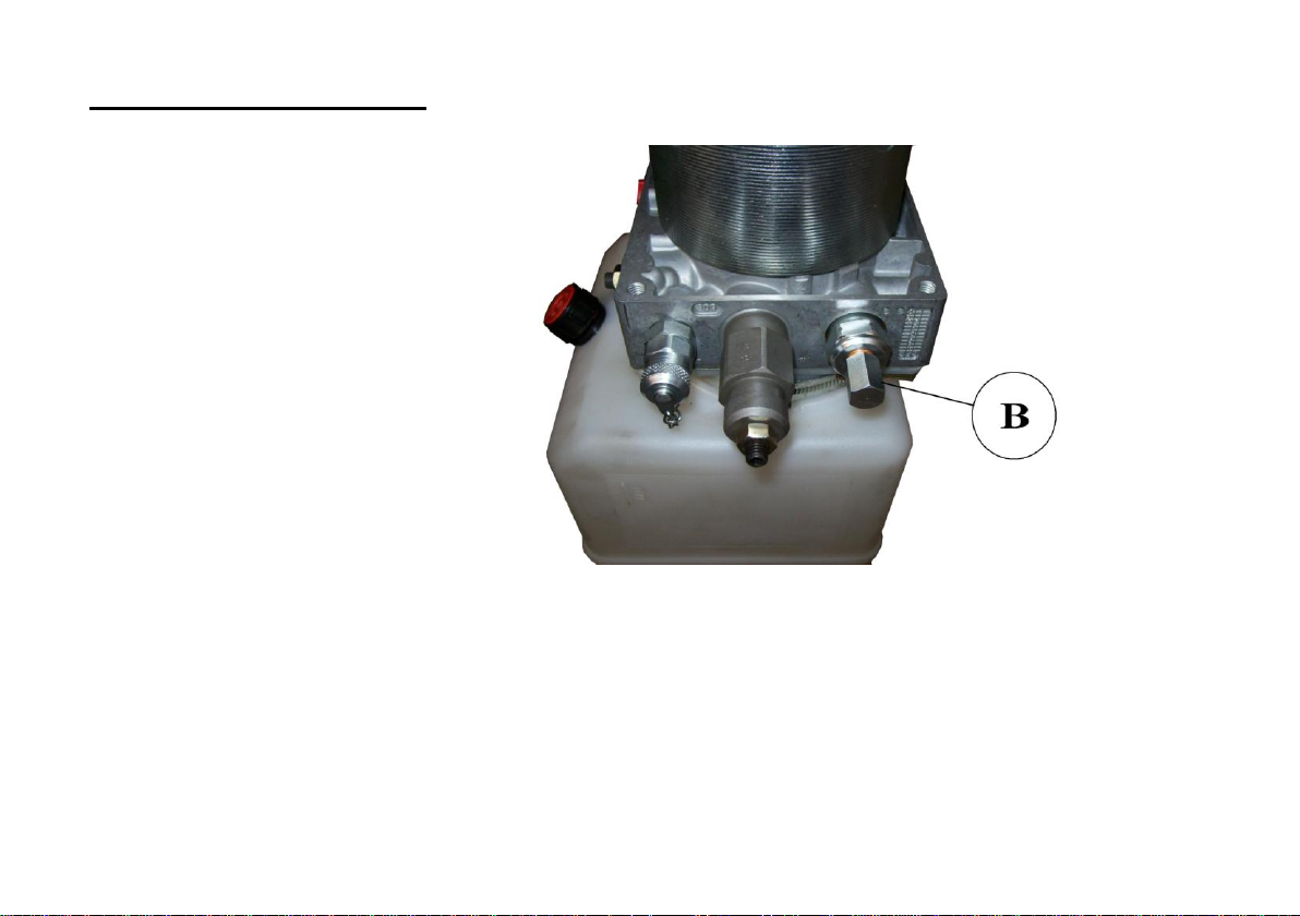
EMERGENCY DESCENT OF
THE FORKS
If the forks are suddenly blocked
in the top position, there is a way
of putting them down:
1. Turn off the key.
2. Open the box key where the
motorpump is located.
3. Verify that there are no
obstacles under the forks.
4. Take off the hexagonal cover
(B with a nº 13 key.
5. Faten the bolt with a 4mm
allen key tol et the fork go
down.
6.7
Page 34

7. LONG WAREHOUSING
LONG TIME WAREHOUSING
When the lifter is not going to be
used for a long time, keep it in a
dry and clean place, and follow
the following instructions:
1. Clean the lifter as explained
before.
2. Charge the batteries
completely.
3. Place the lifter in a horizontal
position.
4. Dissemble the batteries and put
them in a dry and fresh place.
WARNING
When there is no inside area
available, place the lifter in a
horizontal area and cover it
completely with a waterproof
plastic cover.
For warehousing for a longer
period, please contact
technical service.
WARNING
Don not use a waterproof cover
made of vinyl: it may cause
static electricity and
subsequently produce flames
with the batteries gasses.
6.8
Page 35

SERVICE DURING THE
WAREHOUSING
1. Charge batteries every two
months.
2. Make visual inspections to
verify that there is no corrosion.
3. Clean the dirty areas and apply
anticorrosion if needed.
POST-WAREHOUSING
SERVICES
1. Remove the grease of the
exposed areas of the hydraulic
cylinders.
2. Charge the batteries
completely.
3. Turn on the key to confirm
batteries are completely
charged
4. Go ahead with the tests of page
2.13
7.2
Page 36
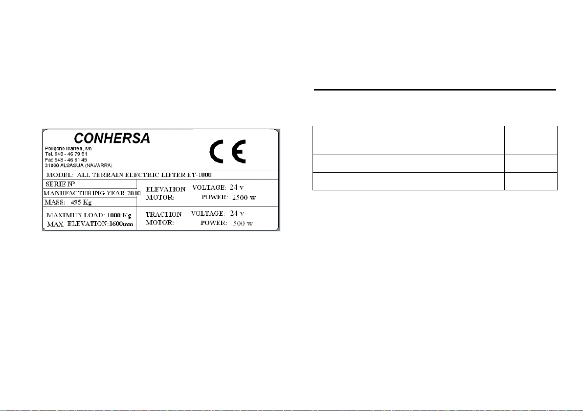
MAXIMUM FORWARD-REVERSE
SPEED
< 1,2 m/s
MAXIMUM LOAD PERMITTED
1.000 kg
MAXIMUM FORKS ELEVATION
1600 mm
8. TECHNICAL SPECIFICATINOS
In this plaque, located at the right hand side, following
information should be seen: Serial number, traction
motor, elevation motor, tyres pressure, etc.
MAIN PARAMETERS
WARNING
Do not try to exceed the above parameters.
8.1
 Loading...