

Congatec conga-TCA 047001, conga-TCA 047004, conga-TCA 047002, conga-TCA 047003, COM Express conga-TCA User Manual
Page 1
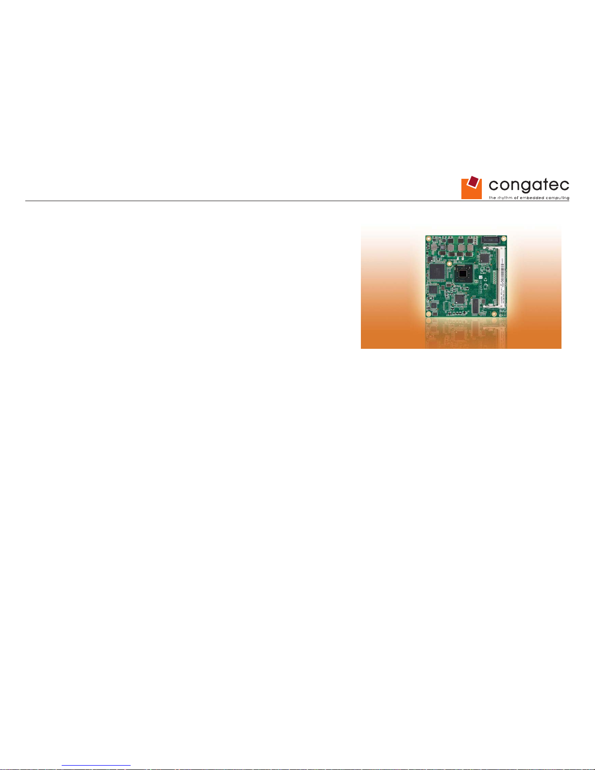
COM Express™ conga-TCA
2nd Generation Dual Core Intel® Atom™ processor with an Intel® NM10 express chipset
User’s Guide
Revision 1.0
Page 2
Copyright © 2012 congatec AG TCEDm10 2/94
Revision History
Revision Date (yyyy.mm.dd) Author Changes
0.1 2012.08.27 AEM • Preliminary release
0.2 2013.03.13 AEM
• Added Microsoft Windows 8 support in section 1.2 “Supported Operating System“.
• Updated section 1.3 “Mechanical Dimension” and section 3 “Heatspreader” to reect the actual heatspreader thickness of 4mm.
• Corrected the statement that the Intel® CG82NM10 (NM10) PCH found on the conga-TCA offers a single channel LVDS interface in
section 4.1.10 “LCD”.
• Updated section 4.1.14 “Power Control”.
• Deleted the wake event signal “PME#” from section 6.4 “ACPI Suspend Modes and Resume Events” because this signal is not supported
in COM Express type 6 specication.
• Updated section 9 “BIOS Setup Description”.
• Added BIOS binary size in section 10 “Additional BIOS Features”.
• Added section 10.1 “Supported Flash Devices”.
1.0 2013.08.09 AEM
• Updated section 9 “BIOS Setup Description”.
• Updated section 10.1 “Supported Flash Devices”.
• Ofcial release
Page 3
Copyright © 2012 congatec AG TCEDm10 3/94
Preface
This user’s guide provides information about the components, features, connectors and BIOS Setup menus available on the conga-TCA. It is
one of three documents that should be referred to when designing a COM Express™ application. The other reference documents that should
be used include the following:
COM Express™ Design Guide
COM Express™ Specication
The links to these documents can be found on the congatec AG website at www.congatec.com
Disclaimer
The information contained within this user’s guide, including but not limited to any product specication, is subject to change without notice.
congatec AG provides no warranty with regard to this user’s guide or any other information contained herein and hereby expressly disclaims
any implied warranties of merchantability or tness for any particular purpose with regard to any of the foregoing. congatec AG assumes
no liability for any damages incurred directly or indirectly from any technical or typographical errors or omissions contained herein or for
discrepancies between the product and the user’s guide. In no event shall congatec AG be liable for any incidental, consequential, special, or
exemplary damages, whether based on tort, contract or otherwise, arising out of or in connection with this user’s guide or any other information
contained herein or the use thereof.
Intended Audience
This user’s guide is intended for technically qualied personnel. It is not intended for general audiences.
Lead-Free Designs (RoHS)
All congatec AG designs are created from lead-free components and are completely RoHS compliant.
Electrostatic Sensitive Device
All congatec AG products are electrostatic sensitive devices and are packaged accordingly. Do not open or handle a congatec AG product
except at an electrostatic-free workstation. Additionally, do not ship or store congatec AG products near strong electrostatic, electromagnetic,
magnetic, or radioactive elds unless the device is contained within its original manufacturer’s packaging. Be aware that failure to comply with
these guidelines will void the congatec AG Limited Warranty.
Page 4
Copyright © 2012 congatec AG TCEDm10 4/94
Symbols
The following symbols are used in this user’s guide:
Warning
Warnings indicate conditions that, if not observed, can cause personal injury.
Caution
Cautions warn the user about how to prevent damage to hardware or loss of data.
Note
Notes call attention to important information that should be observed.
Terminology
Term Description
GB Gigabyte (1,073,741,824 bytes)
GHz Gigahertz (one billion hertz)
kB Kilobyte (1024 bytes)
MB Megabyte (1,048,576 bytes)
Mbit Megabit (1,048,576 bits)
kHz Kilohertz (one thousand hertz)
MHz Megahertz (one million hertz)
TDP Thermal Design Power
PCIe PCI Express
SATA Serial AT A
PEG PCI Express Graphics
PCH Platform Controller Hub
PATA Parallel AT A
T.O.M. Top of memory = max. DRAM installed
HDA High Denition Audio
I/F Interface
N.C. Not connected
N.A. Not available
TBD To be determined
Page 5
Copyright © 2012 congatec AG TCEDm10 5/94
Trademarks
Product names, logos, brands, and other trademarks featured or referred to within this user’s guide, or the congatec website, are the property
of their respective trademark holders. These trademark holders are not afliated with congatec AG, our products, or our website.
Warranty
congatec AG makes no representation, warranty or guaranty, express or implied regarding the products except its standard form of limited
warranty (“Limited Warranty”). congatec AG may in its sole discretion modify its Limited Warranty at any time and from time to time.
Beginning on the date of shipment to its direct customer and continuing for the published warranty period, congatec AG represents that the
products are new and warrants that each product failing to function properly under normal use, due to a defect in materials or workmanship or
due to non conformance to the agreed upon specications, will be repaired or exchanged, at congatec AG’
s option and expense.
Customer will obtain a Return Material Authorization (“RMA”) number from congatec AG prior to returning the non conforming product freight
prepaid. congatec AG will pay for transporting the repaired or exchanged product to the customer.
Repaired, replaced or exchanged product will be warranted for the repair warranty period in effect as of the date the repaired, exchanged or
replaced product is shipped by congatec AG, or the remainder of the original warranty, whichever is longer. This Limited Warranty extends to
congatec AG’s direct customer only and is not assignable or transferable.
Except as set forth in writing in the Limited Warranty, congatec AG makes no performance representations, warranties, or guarantees, either
express or implied, oral or written, with respect to the products, including without limitation any implied warranty (a) of merchantability, (b) of
tness for a particular purpose, or (c) arising from course of performance, course of dealing, or usage of trade.
congatec AG shall in no event be liable to the end user for collateral or consequential damages of any kind. congatec AG shall not otherwise
be liable for loss, damage or expense directly or indirectly arising from the use of the product or from any other cause. The sole and exclusive
remedy against congatec AG, whether a claim sound in contract, warranty, tort or any other legal theory, shall be repair or replacement of the
product only
Page 6
Copyright © 2012 congatec AG TCEDm10 6/94
COM Express™ Concept
COM Express™ is an open industry standard dened specically for COMs (computer on modules). It’s creation provides the ability to make a
smooth transition from legacy parallel interfaces to the newest technologies based on serial buses available today. COM Express™ modules
are available in following form factors:
• Compact 95mm x 95mm
• Basic 125mm x 95mm
• Extended 155mm x 110mm
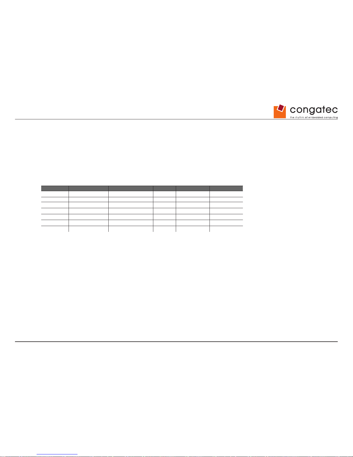
The COM Express™ specication 2.0 denes seven different pinout types.
Types Connector Rows PCI Express Lanes PCI IDE Channels LAN ports
Type 1 A-B Up to 6 1
Type 2 A-B C-D Up to 22 32 bit 1 1
Type 3 A-B C-D Up to 22 32 bit 3
Type 4 A-B C-D Up to 32 1 1
Type 5 A-B C-D Up to 32 3
Type 6 A-B C-D Up to 24 1
Type 10 A-B Up to 4 1
conga-TCA module utilize the Type 6 pinout denition. They are equipped with two high performance connectors that ensure stable data
throughput.
The COM (computer on module) integrates all the core components and is mounted onto an application specic carrier board. COM modules
are a legacy-free design (no Super I/O, PS/2 keyboard and mouse) and provide most of the functional requirements for any application. These
functions include, but are not limited to, a rich complement of contemporary high bandwidth serial interfaces such as PCI Express, Serial ATA,
USB 2.0, and Gigabit Ethernet. The Type 6 pinout provides the ability to offer PCI Express, Serial ATA, and LPC options thereby expanding
the range of potential peripherals. The robust thermal and mechanical concept, combined with extended power-management capabilities, is
perfectly suited for all applications.
Carrier board designers can utilize as little or as many of the I/O interfaces as deemed necessary. The carrier board can therefore provide all
the interface connectors required to attach the system to the application specic peripherals. This versatility allows the designer to create a
dense and optimized package, which results in a more reliable product while simplifying system integration. Most importantly, COM Express™
modules are scalable, which means once an application has been created there is the ability to diversify the product range through the use of
different performance class or form factor size modules. Simply unplug one module and replace it with another, no redesign is necessary.
Page 7
Copyright © 2012 congatec AG TCEDm10 7/94
Certication
congatec AG is certied to DIN EN ISO 9001 standard.
Technical Support
congatec AG technicians and engineers are committed to providing the best possible technical support for our customers so that our products
can be easily used and implemented. We request that you rst visit our website at www.congatec.com for the latest documentation, utilities and
drivers, which have been made available to assist you. If you still require assistance after visiting our website then contact our technical support
department by email at [email protected]
C
E
R
T
I
F
I
C
A
T
I
O
N
I
S
O
9
0
0
1
TM
Page 8
Copyright © 2012 congatec AG TCEDm10 8/94
conga-TCA Options Information
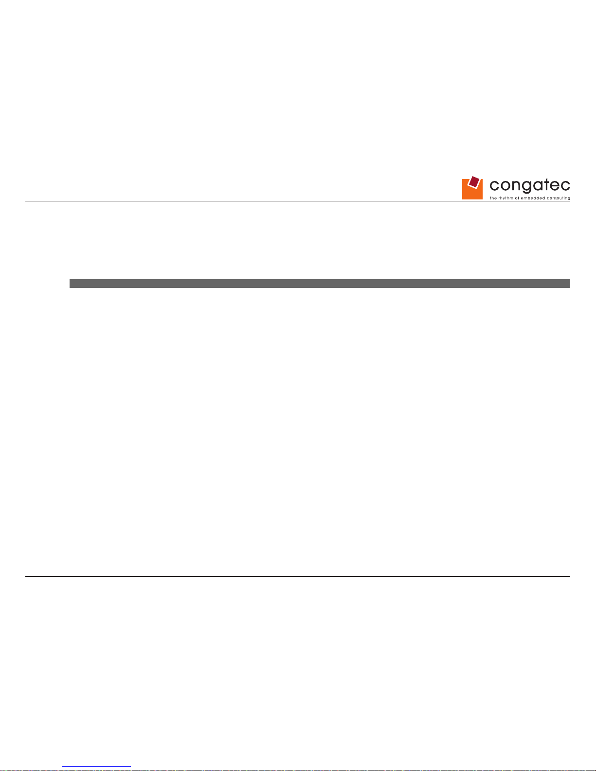
The conga-TCA is available in four different variants. This user’s guide describes all of these variants. The table below shows the different
congurations available. Check for the Part No. that applies to your product. This will tell you what options described in this user’s guide are
available on your particular module.
conga-TCA
Part-No. 047001 047002 047003 047004
Processor Intel
®
Atom™ N2600 Dual Core
1.60 GHz
Intel
®
Atom™ N2800 Dual Core
1.86 GHz
Intel
®
Atom™ D2550 Dual Core
1.86 GHz
Intel
®
Atom™ D2550 (USB 3.0) Dual Core
1.86 GHz
L2 Cache 1 MByte 1 MByte 1 MByte 1 MByte
PEG No No No No
SDVO No No No No
DisplayPort (DP) Yes Yes Yes Yes
HDMI Yes Yes Yes Yes
Processor TDP 3.5 W 6.5 W 10 W 10 W
Page 9
Copyright © 2012 congatec AG TCEDm10 9/94
Contents
1 Specications ...........................................................................12
1.1 Feature List .............................................................................. 12
1.2 Supported Operating Systems ................................................. 13
1.3 Mechanical Dimensions ........................................................... 13
1.4 Supply Voltage Standard Power ..............................................14
1.4.1 Electrical Characteristics ..........................................................14
1.4.2 Rise Time .................................................................................14
1.5 Power Consumption ................................................................. 15
1.5.1 conga-TCA Intel® Atom™ N2600 Dual Core 1.6 GHz 1MB Cache
16
1.5.2 conga-TCA Intel® Atom™ N2800 Dual Core 1.86 GHz 1MB Cache
16
1.5.3 conga-TCA Intel® Atom™ D2550 Dual Core 1.86 GHz 1MB Cache
17
1.5.4 conga-TCA Intel® Atom™ D2550 (USB 3.0) Dual Core 1.86 GHz
1MB Cache ..............................................................................17
1.6 Supply Voltage Battery Power .................................................18
1.6.1 CMOS Battery Power Consumption ........................................18
1.7 Environmental Specications ................................................... 18
2 Block Diagram ..........................................................................19
3 Heatspreader ...........................................................................20
3.1 Heatspreader Dimensions ....................................................... 21
4 Connector Subsystems Rows A, B, C, D .................................22
4.1 Primary Connector Rows A and B ............................................23
4.1.1 Serial ATA™ (SATA) .................................................................23
4.1.2 USB 2.0 ....................................................................................23
4.1.3 High Denition Audio (HDA) Interface ......................................23
4.1.4 Gigabit Ethernet ......................................................................23
4.1.5 LPC Bus ...................................................................................24
4.1.6 I²C Bus Fast mode ...................................................................24
4.1.7 PCI Express™ .........................................................................24
4.1.8 ExpressCard™ .........................................................................24
4.1.9 Graphics Output (VGA/CRT) ...................................................24
4.1.10 LCD ..........................................................................................25
4.1.11 SPI .................................................................................... .......25
4.1.12 General Purpose Serial Interface .............................................25
4.1.13 General Purpose Input/Output .................................................25
4.1.14 Power Control ..........................................................................26
4.1.15 Power Management .................................................................28
4.2 Secondary Connector Rows C and D ...................................... 29
4.2.1 USB 3.0 ....................................................................................29
4.2.2 HDMI ........................................................................................29
4.2.3 DisplayPort (DP) ......................................................................29
5 Additional Features ..................................................................30
5.1 congatec Board Controller (cBC) ............................................. 30
5.2 Board Information .................................................................... 30
5.3 Watchdog .................................................................................30
5.4 I
2
C Bus .....................................................................................30
5.5 Power Loss Control .................................................................. 31
5.6 Embedded BIOS ...................................................................... 31
5.6.1 CMOS Backup in Non Volatile Memory ...................................31
5.6.2 OEM CMOS Default Settings and OEM BIOS Logo ................31
5.6.3 OEM BIOS Code ......................................................................31
5.6.4 congatec Battery Management Interface .................................32
5.6.5 API Support (CGOS/EAPI) ......................................................32
5.7 Security Features ..................................................................... 33
5.8 Suspend to Ram ...................................................................... 33
6 conga Tech Notes ....................................................................34
6.1 Intel
®
Matrix Storage Technology ............................................34
6.1.1 AHCI ........................................................................................34
6.2 Intel
®
Processor Features ........................................................34
6.2.1 Thermal Monitor and Catastrophic Thermal Protection ...........34
6.2.2 Processor Performance Control ...............................................35
6.3 Thermal Management .............................................................. 35
6.4 ACPI Suspend Modes and Resume Events ............................ 37
6.5 USB 2.0 EHCI Host Controller Support ................................... 38
7 Signal Descriptions and Pinout Tables .....................................39
Page 10
Copyright © 2012 congatec AG TCEDm10 10/94
7.1 A-B Connector Signal Descriptions .......................................... 40
7.2 A-B Connector Pinout .............................................................. 50
7.3 C-D Connector Signal Descriptions ......................................... 52
7.4 C-D Connector Pinout .............................................................. 62
7.5 Boot Strap Signals ................................................................... 64
8 System Resources ...................................................................65
8.1 System Memory Map ............................................................... 65
8.2 I/O Address Assignment ...........................................................65
8.2.1 LPC Bus ...................................................................................65
8.3 Interrupt Request (IRQ) Lines .................................................. 66
8.4 PCI Conguration Space Map ................................................. 68
8.5 PCI Interrupt Routing Map ....................................................... 69
8.6 I²C Bus ..................................................................................... 69
8.7 SM Bus .................................................................................... 69
9 BIOS Setup Description ...........................................................70
9.1 Entering the BIOS Setup Program. .......................................... 70
9.1.1 Boot Selection Popup ..............................................................70
9.2 Setup Menu and Navigation ..................................................... 70
9.3 Main Setup Screen .................................................................. 71
9.3.1 Intel RC Version Submenu .......................................................72
9.4 Advanced Setup ....................................................................... 72
9.4.1 Graphics Submenu ..................................................................73
9.4.2 Watchdog Submenu.................................................................74
9.4.3 Hardware Monitoring Submenu ...............................................76
9.4.4 PCI Submenu ...........................................................................77
9.4.4.1 PIRQ Routing & IRQ Reservation Submenu ...........................78
9.4.5 ACPI Submenu ........................................................................78
9.4.6 RTC Wake Settings Submenu .................................................79
9.4.7 CPU Submenu .........................................................................79
9.4.8 Memory Submenu ....................................................................80
9.4.9 Chipset Submenu ....................................................................80
9.4.9.1 IO Hub Devices Submenu .......................................................81
9.4.9.2 PCI Express Port Submenu .....................................................82
9.4.10 SATA Submenu ........................................................................83
9.4.11 iFFS Submenu .........................................................................83
9.4.12 USB Submenu .........................................................................84
9.4.13 Super I/O Submenu .................................................................85
9.4.14 Console Redirection Submenu ................................................85
9.4.14.1 Console Redirection Settings Submenu ..................................86
9.4.14.2 Console Redirection Settings (EMS) Submenu .......................86
9.4.15 Network Stack Submenu .........................................................87
9.5 Boot Setup ............................................................................... 87
9.5.1 Boot Settings Conguration .....................................................87
9.5.1.1 CSM & Option ROM Parameters Submenu .............................89
9.6 Security Setup .......................................................................... 90
9.6.1 Security Settings ......................................................................90
9.6.1.1 Trusted Computing...................................................................90
9.6.2 Hard Disk Security ...................................................................90
9.6.3 Save & Exit Menu ....................................................................91
10 Additional BIOS Features ........................................................92
10.1 Supported Flash Devices .........................................................92
10.2 Updating the BIOS ...................................................................92
10.3 BIOS Security Features ...........................................................92
10.4 Hard Disk Security Features ....................................................93
11 Industry Specications .............................................................94
Page 11
Copyright © 2012 congatec AG TCEDm10 11/94
List of Tables
Table 1 Feature Summary ....................................................................12
Table 2 Signal Tables Terminology Descriptions ..................................39
Table 3 Intel
®
High Denition Audio Link Signals Descriptions .............40
Table 4 Gigabit Ethernet Signal Descriptions .......................................41
Table 5 Serial ATA Signal Descriptions .................................................42
Table 6 PCI Express Signal Descriptions (general purpose) ................43
Table 7 ExpressCard Support Pins Descriptions ..................................44
Table 8 LPC Signal Descriptions ..........................................................44
Table 9 USB Signal Descriptions ..........................................................45
Table 10 CRT Signal Descriptions ..........................................................45
Table 11 LVDS Signal Descriptions ........................................................46
Table 12 SPI BIOS Flash Interface Signal Descriptions .........................47
Table 13 Miscellaneous Signal Descriptions ..........................................47
Table 14 General Purpose I/O Signal Descriptions ................................48
Table 15 Power and System Management Signal Descriptions .............48
Table 16 General Purpose Serial Interface Signal Descriptions .............49
Table 17 Power and GND Signal Descriptions .......................................49
Table 18 Connector A-B Pinout ..............................................................50
Table 19 PCI Express Signal Descriptions (general purpose) ................52
Table 20 USB Signal Descriptions ..........................................................52
Table 21 PCI Express Signal Descriptions (x16 Graphics) .....................53
Table 22 DDI Signal Description .............................................................55
Table 23 HDMI Signal Descriptions ........................................................57
Table 24 DisplayPort (DP) Signal Descriptions ......................................59
Table 25 Module Type Denition Signal Description ..............................61
Table 26 Power and GND Signal Descriptions .......................................61
Table 27 Connector C-D Pinout ..............................................................62
Table 28 Boot Strap Signal Descriptions ................................................64
Table 29 Memory Map ............................................................................65
Table 30 IRQ Lines in PIC mode ............................................................66
Table 31 IRQ Lines in APIC mode ..........................................................67
Table 32 PCI Conguration Space Map .................................................68
Table 33 PCI Interrupt Routing Map .......................................................69
Page 12
Copyright © 2012 congatec AG TCEDm10 12/94
1 Specications
1.1 Feature List
Table 1 Feature Summary
Form Factor
Based on COM Express™ standard pinout Type 6 Rev. 2.1 (Compact size 95 x 95mm)
Processor
Intel
®
Atom™ N2600 Dual Core 1.60 GHz 1-MByte L2 Cache
Intel
®
Atom™ N2800 Dual Core 1.86 GHz 1-MByte L2 Cache
Intel
®
Atom™ D2550 Dual Core 1.86 GHz 1-MByte L2 Cache
Intel
®
Atom™ D2550 (USB 3.0) Dual Core 1.86 GHz 1-MByte L2 Cache
Memory
1 socket: SO-DIMM DDR3 up to 1066MT/s, maximum 4-GByte.
Chipset
Intel
®
NM10 Express Chipset: Intel
®
CG82NM10 PCH
Audio
HDA (High Denition Audio)/digital audio interface with support for multiple codecs
Ethernet
Gigabit Ethernet: Realtek 8111E
Graphics Options
Integrated graphics with OpenGL 3.0 and DirectX9 support.
Two independent pipelines for full dual view support.
• CRT Interface 350 MHz RAMDAC Resolutions up to 1920x1200 @ 60Hz
• Flat panel Interface (integrated) with 25-112MHz single-channel LVDS Transmitter.
Supports:
• Single-channel LVDS interface: 1 x 18 bpp (D2000/N2000 series) or 1 x 24 bpp
(D2000 series only).
• VESA LVDS color mappings.
• Automatic Panel Detection via EPI (Embedded Panel Interface based on VESA
EDID™ 1.3)
• Resolutions up to 1366x768 (WXGA) for 18 bpp and up to 1440x900 (WXGA+) for
24 bpp
• 2x DDI (Digital Display Interface) with support for:
• 2x DisplayPort 1.1 on digital ports B and C.
Multiplexed with HDMI/DVI ports. Supports hot plug
detect.
• 2x HDMI ports on digital ports B and C. Multiplexed
with DP/DVI ports. Supports hot plug detect.
• 2x DVI ports on digital ports B and C. Multiplexed
with DP/HDMI ports. Supports hot plug detect.
Peripheral
Interfaces
• 2x Serial AT A
®
II, with up to 3 Gb/s data transfer rate.
• Up to x5 PCI Express® Lanes if the optional USB 3.0 is not implemented. Each root
port supports full 2.5 Gb/s bandwidth in each direction per x1 link
• 8x USB 2.0 (UHCI and EHCI)
• 2x USB 3.0
• LPC Bus
• I²C Bus, Fast Mode, multimaster
• SM Bus
BIOS
AMI Aptio
®
UEFI 2.x rmware, 4MByte serial SPI with congatec Embedded BIOS features
Power Management
ACPI 3.0 compliant with battery support. Also supports Suspend to RAM (S3).
Note
Some of the features mentioned in the above Feature Summary are optional. Check the article number of your module and compare it to the
option information list on page 8 of this user’s guide to determine what options are available on your particular module.
Page 13
Copyright © 2012 congatec AG TCEDm10 13/94
1.2 Supported Operating Systems
The conga-TCA supports the following operating systems.
• Microsoft® Windows
®
8 (32 bit)
• Microsoft
®
Windows® 7
• Microsoft
®
Windows® XP
• Microsoft
®
Windows
®
Embedded Standard
• Linux
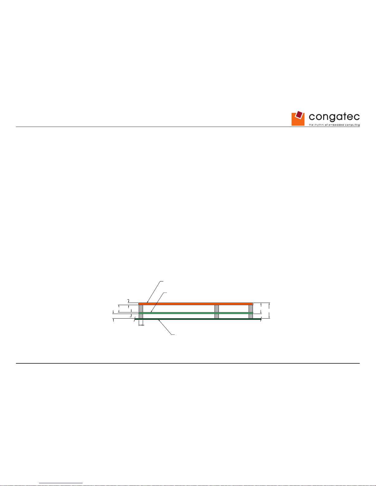
1.3 Mechanical Dimensions
• 95.0 mm x 95.0 mm (3.75” x 3.75”)
• Height approximately 18 or 21mm (including heatspreader) depending on the carrier board connector that is used. If the 5mm
(height) carrier board connector is used then approximate overall height is 18mm. If the 8mm (height) carrier board connector is
used then approximate overall height is 21mm.
4.00
Heatspreader
Module PCB
Carrier Board PCB
7.00
5.00
2.00
4.50
13.00
18.00
Page 14
Copyright © 2012 congatec AG TCEDm10 14/94
1.4 Supply Voltage Standard Power
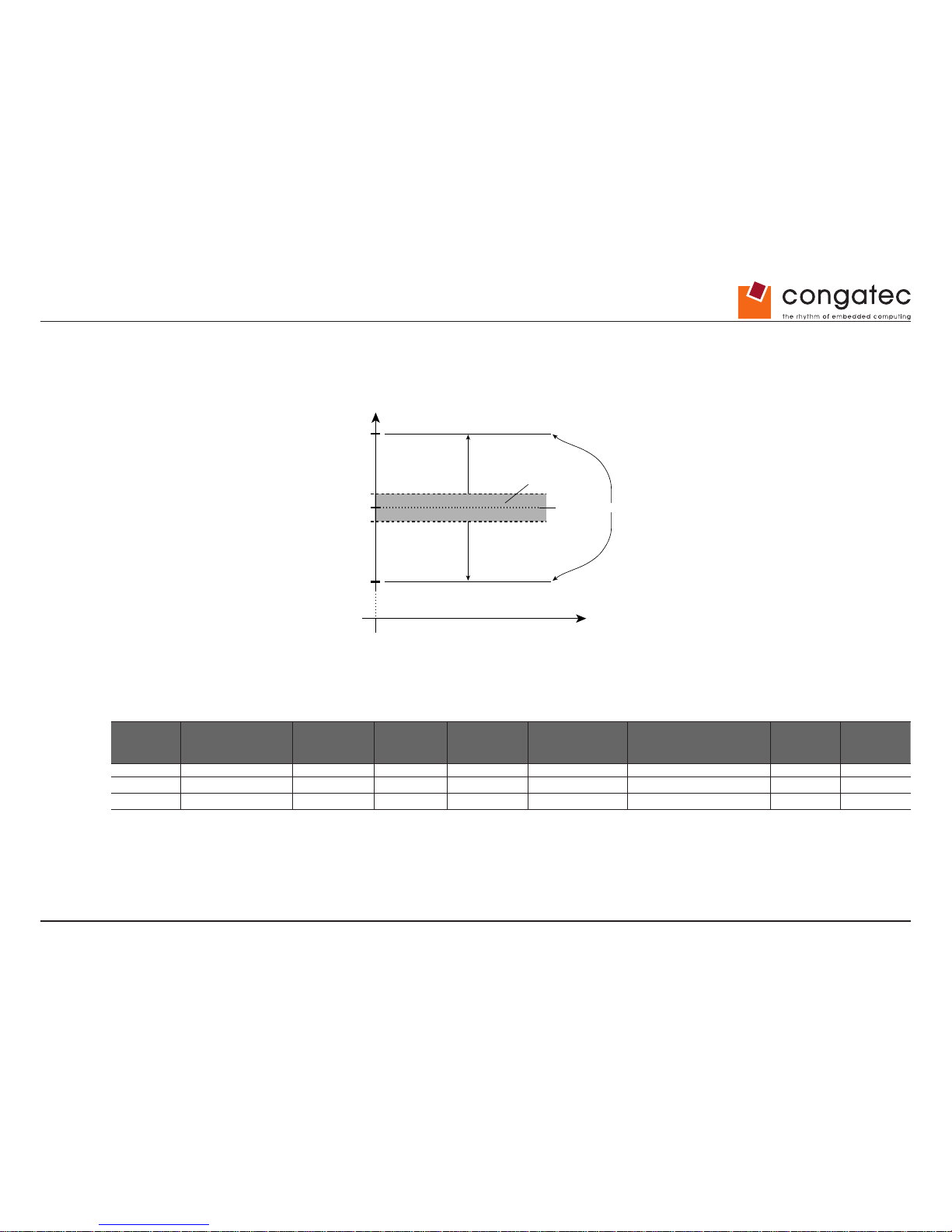
• 12V DC ± 5%
The dynamic range shall not exceed the static range.
1.4.1 Electrical Characteristics
Power supply pins on the module’s connectors limit the amount of input power. The following table provides an overview of the limitations for
pinout Type 6 (dual connector, 440 pins).
Power Rail Module Pin Current
Capability (Amps)
Nominal Input
(Volts)
Input Range
(Volts)
Derated Input
(Volts)
Max. Input Ripple
(10Hz to 20MHz)
(mV)
Max. Module Input Power
(w. derated input)
(Watts)
Assumed
Conversion
Efciency
Max. Load
Power
(Watts)
VCC_12V 12 12 11.4-12.6 11.4 +/- 100 137 85% 116
VCC_5V-SBY 2 5 4.75-5.25 4.75 +/- 50 9
VCC_RTC 0.5 3 2.0-3.3 +/- 20
1.4.2 Rise Time
The input voltages shall rise from 10% of nominal to 90% of nominal at a minimum rise time of 250V/s. The smooth turn-on requires that, during
the 10% to 90% portion of the rise time, the slope of the turn-on waveform must be positive.
Nominal Static Range
Dynamic Range
Absolute Minimum
Absolute Maximum12.60V
11.40V
12V
12.10V
11.90V
Page 15
Copyright © 2012 congatec AG TCEDm10
15/94
1.5 Power Consumption
The power consumption values listed in this document were measured under a controlled environment. The hardware used for testing includes
a conga-TCA module, conga-Cdebug carrier board, CRT monitor, SATA drive, and USB keyboard. The conga-Cdebug is modied so that
the 12V input is only routed to the module and all other circuity on the carrier itself is powered by the 5V input. The SATA drive was powered
externally by an ATX power supply so that it does not inuence the power consumption value that is measured for the module. The USB
keyboard was detached once the module was congured within the OS. All recorded values were averaged over a 30 second time period.
Cooling of the module was done by the module specic heatspreader and a fan cooled heatsink to measure the power consumption under
normal thermal conditions.
The conga-Cdebug originally does not provide 5V standby power. Therefore, an extra 5V_SB connection without any external loads was made.
Using this setup, the power consumption of the module in S3 (Standby) mode was measured directly.
Each module was measured while running Windows 7 Professional 32Bit, Hyper Threading enabled, Speed Step enabled and Power Plan set
to “Power Saver”. This setting ensures that Core™ processors run in LFM (lowest frequency mode) with minimal core voltage during desktop
idle. Each module was tested while using a 1GB memory modules. Using different sizes of RAM will cause slight variances in the measured
results.
To measure the worst case power consumption the cooling solution was removed and the CPU core temperature was allowed to run up to
between 95° and 100°C while running 100% workload with the Power Plan set to “Balanced”. The peak current value was then recorded. This
value should be taken into consideration when designing the system’s power supply to ensure that the power supply is sufcient during worst
case scenarios.
Power consumption values were recorded during the following stages:
Windows 7 (32 bit)
• Desktop Idle (power plan = Power Saver)
• 100% CPU workload (see note below, power plan = Power Saver)
• 100% CPU workload at approximately 100°C peak power consumption (power plan = Balanced)
• Suspend to RAM. Supply power for S3 mode is 5V.
Note
A software tool was used to stress the CPU to maximum frequency.
Page 16
Copyright © 2012 congatec AG TCEDm10
16/94
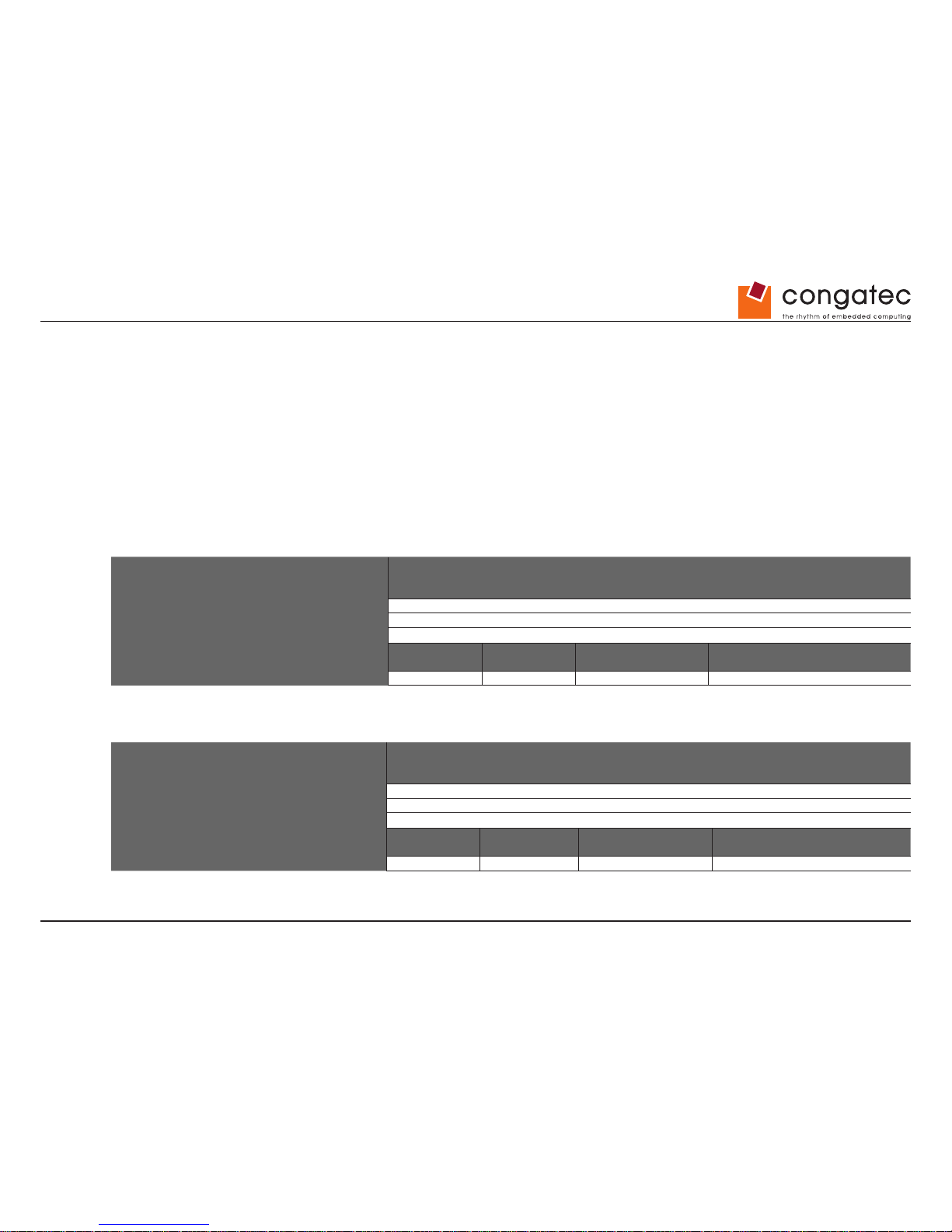
Processor Information
In the following power tables, there is some additional information about the processors.
Intel
®
describes the type of manufacturing process used for each processor. The following term is used:
nm=nanometer
The manufacturing process description is included in the power tables as well. See example below. For information about the manufacturing
process visit Intel
®
’s website.
Intel
®
Atom™ N2600 1.6 GHz 1MB L2 Cache
32nm
1.5.1 conga-TCA Intel® Atom™ N2600 Dual Core 1.6 GHz 1MB Cache
conga-TCA Art. No. 047001 Intel® Atom™ N2600 1.6 GHz 1MB L2 Cache
32nm
Layout Rev. TCEDLA0 /BIOS Rev. TCEDR006
Max Turbo Frequency
Not supported
Memory Size
1GB
Operating System
Windows 7 (32 bit)
Power State Desktop Idle 100% workload 100% workload approx.
100°C CPU temp (peak)
Suspend to Ram (S3) 5V Input
Power
Power consumption (measured in Amperes/Watts)
0.46 A/5.5 W (12V) 0.66 A/7.9 W (12V) 0.68 A/8.2 W (12V) 0.1 A/0.5 W (5V)
1.5.2 conga-TCA Intel® Atom™ N2800 Dual Core 1.86 GHz 1MB Cache
conga-TCA Art. No. 047002 Intel® Atom™ N2800 1.86 GHz 1MB L2 Cache
32nm
Layout Rev. TCEDLA0 /BIOS Rev. TCEDR006
Max Turbo Frequency
Not supported
Memory Size
1GB
Operating System
Windows 7 (32 bit)
Power State Desktop Idle 100% workload 100% workload approx.
100°C CPU temp (peak)
Suspend to Ram (S3) 5V Input
Power
Power consumption (measured in Amperes/Watts)
0.57 A/6.8 W (12V) 0.83 A/9.9 W (12V) 1.03 A/12.3 W (12V) 0.1 A/0.5 W (5V)
Page 17
Copyright © 2012 congatec AG TCEDm10 17/94
1.5.3 conga-TCA Intel® Atom™ D2550 Dual Core 1.86 GHz 1MB Cache
conga-TCA Art. No. 047003 Intel® Atom™ D2550 1.86 GHz 1MB L2 Cache
32nm
Layout Rev. TCEDLA0 /BIOS Rev. TCEDR006
Max Turbo Frequency
Not supported
Memory Size
1GB
Operating System
Windows 7 (32 bit)
Power State Desktop Idle 100% workload 100% workload approx.
100°C CPU temp (peak)
Suspend to Ram (S3) 5V Input
Power
Power consumption (measured in Amperes/Watts)
0.67 A/8.0 W (12V) 0.97 A/11.6 W (12V) 1.07 A/12.8 W (12V) 0.1 A/0.5 W (5V)
1.5.4 conga-TCA Intel® Atom™ D2550 (USB 3.0) Dual Core 1.86 GHz 1MB Cache
conga-TS67 Art. No. 047004 Intel® Atom™ D2550 1.86 GHz 1MB L2 Cache
32nm
Layout Rev. TCEDLA0 /BIOS Rev. TCEDR006
Max Turbo Frequency
Not supported
Memory Size
1GB
Operating System
Windows 7 (32 bit)
Power State Desktop Idle 100% workload 100% workload approx.
100°C CPU temp (peak)
Suspend to Ram (S3) 5V Input
Power
Power consumption (measured in Amperes/Watts)
0.7 A/8.4 W (12V) 1.0 A/11.9 W (12V) 1.2 A/14.6 W (12V) 0.1 A/0.5 W (5V)
Note
All recorded power consumption values are approximate and only valid for the controlled environment described earlier. 100% workload refers
to the CPU workload and not the maximum workload of the complete module. Supply power for S3 mode is 5V while all other measured modes
are supplied with 12V power. Power consumption results will vary depending on the workload of other components such as graphics engine,
memory, etc.
Page 18
Copyright © 2012 congatec AG TCEDm10 18/94
1.6 Supply Voltage Battery Power
• 2.0V-3.5V DC
• Typical 3V DC
1.6.1 CMOS Battery Power Consumption
RTC @ 20ºC Voltage Current
Integrated in the Intel® CG82NM10 PCH 3V DC 3.51 µA
The CMOS battery power consumption value listed above should not be used to calculate CMOS battery lifetime. You should measure the
CMOS battery power consumption in your customer specic application in worst case conditions, for example during high temperature and
high battery voltage. The self-discharge of the battery must also be considered when determining CMOS battery lifetime. For more information
about calculating CMOS battery lifetime refer to application note AN9_RTC_Battery_Lifetime.pdf, which can be found on the congatec AG
website at www.congatec.com.
1.7 Environmental Specications
Temperature Operation: 0° to 60°C Storage: -20° to +80°C
Humidity Operation: 10% to 90% Storage: 5% to 95%
Caution
The above operating temperatures must be strictly adhered to at all times. When using a heatspreader the maximum operating temperature
refers to any measurable spot on the heatspreader’s surface.
congatec AG strongly recommends that you use the appropriate congatec module heatspreader as a thermal interface between the module
and your application specic cooling solution.
If for some reason it is not possible to use the appropriate congatec module heatspreader, then it is the responsibility of the operator to ensure
that all components found on the module operate within the component manufacturer’
s specied temperature range.
For more information about operating a congatec module without heatspreader contact congatec technical support.
Humidity specications are for non-condensing conditions.
Page 19
Copyright © 2012 congatec AG TCEDm10 19/94
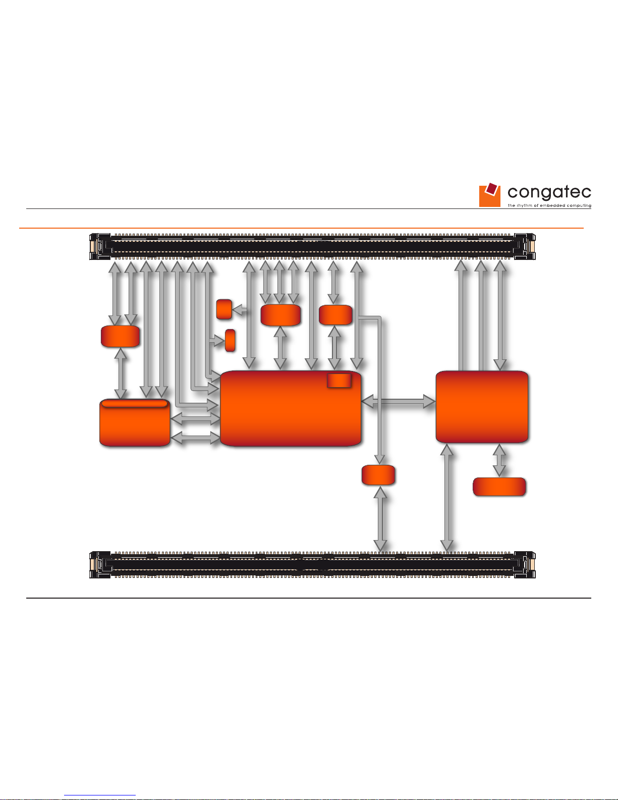
2 Block Diagram
C-D
A-B
PCIe GBE
RTL8111E
PCIe
Switch
Hardware
Monitoring
PCIe2USB3
Intel® NM10
Express Chipset
CG82NM10 PCH
congatec
Board Controller
STM32F100R8
Watchdog
TPM
Intel® Atom™
Processor
N2800
N2600
D2550
DDR3-SODIMM
max. 4 GByte
BIOS
(Flash)
RTC
2x SATA II
8x USB 2.0
HDA
PCIe x1
Gbit Ethernet
Fan Control
SM Bus
SM Bus
SPI
LPC
DMI
x2 (N2000)
x4 (D2000)
SM Bus
Memory Types
(up to 1066MTs)
GPIs/GPOs
2x DP or HDMI
LVDS
2x USB 3.0
optional
CRT
GPIs/GPOs
I²C
PCIe x1
PCIe x1
PCIe x1
PCIe x1
PCIe x1
PCIe x1
If No USB 3.0
PCIe x1
Page 20
Copyright © 2012 congatec AG TCEDm10 20/94
3 Heatspreader
An important factor for each system integration is the thermal design. The heatspreader acts as a thermal coupling device to the module and
its aluminum plate is 4mm thick.
The heatspreader is thermally coupled to the CPU via a thermal gap ller and on some modules it may also be thermally coupled to other heat
generating components with the use of additional thermal gap llers.
Although the heatspreader is the thermal interface where most of the heat generated by the module is dissipated, it is not to be considered as a
heatsink. It has been designed as a thermal interface between the module and the application specic thermal solution. The application specic
thermal solution may use heatsinks with fans, and/or heat pipes, which can be attached to the heatspreader. Some thermal solutions may also
require that the heatspreader is attached directly to the systems chassis thereby using the whole chassis as a heat dissipater.
For additional information about the conga-TCA heatspreader, refer to section 3.1 of this document.
Caution
There are mounting holes on the heatspreader designed to attach the heatspreader to the module. These mounting holes must be used to
ensure that all components that are required to make contact with heatspreader do so. Failure to utilize these mounting holes will result in
improper contact between these components and heatspreader thereby reducing heat dissipation efciency.
Attention must be given to the mounting solution used to mount the heatspreader and module into the system chassis. Do not use a threaded
heatspreader together with threaded carrier board standoffs. The combination of the two threads may be staggered, which could lead to
stripping or cross-threading of the threads in either the standoffs of the heatspreader or carrier board.
Caution
When using PN: 047003 conga-TCA/D2550 and/or PN: 047004 conga-TCA/D2550 xHCI modules in conjunction with the conga-TCA/CSP-T(B)
passive cooling solution, active airow must be provided over the cooling ns. The conga-TCA/CSP-T(B) is not capable of dissipating the heat
generated by these modules without an active airow present.
Page 21
Copyright © 2012 congatec AG TCEDm10 21/94
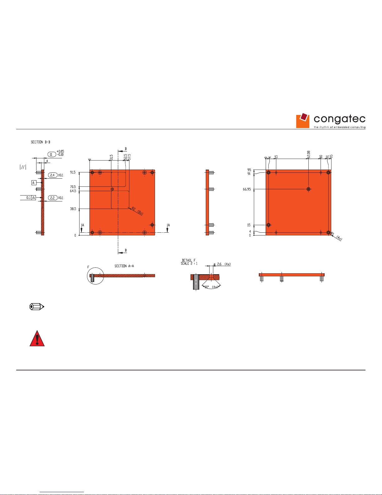
3.1 Heatspreader Dimensions
Note
All measurements are in millimeters. Torque specication for heatspreader screws is 0.3 Nm. Mechanical system assembly mounting shall
follow the valid DIN/IS0 specications.
Caution
When using the heatspreader in a high shock and/or vibration environment, congatec recommends the use of a thread-locking uid on the
heatspreader screws to ensure the above mentioned torque specication is maintained.
Page 22
Copyright © 2012 congatec AG TCEDm10 22/94
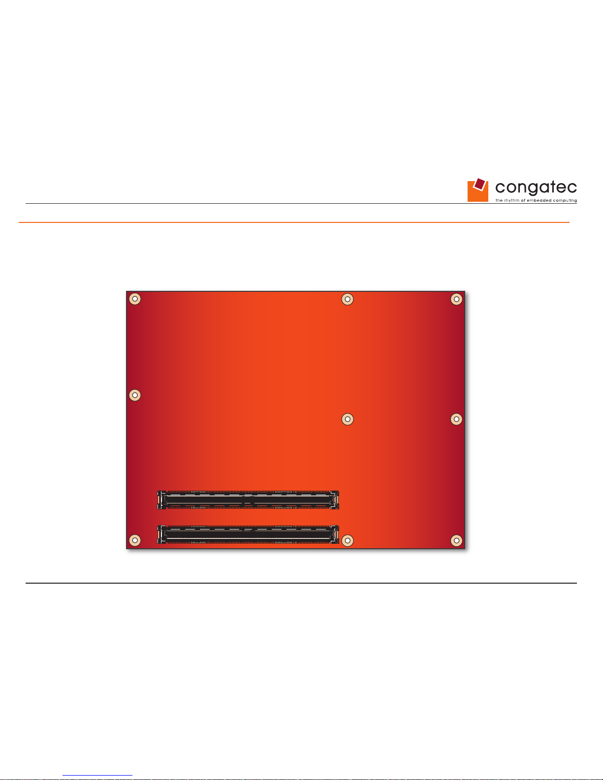
4 Connector Subsystems Rows A, B, C, D
The conga-TCA is connected to the carrier board via two 220-pin connectors (COM Express Type 6 pinout) for a total of 440 pins connectivity.
These connectors are broken down into four rows. The primary connector consists of rows A and B while the secondary connector consists of
rows C and D.
In this view the connectors are seen “through” the module.
top view
A-B
5 PCI Express Lanes
(only 4 when USB 3.0 option present)
General Purpose I/Os
2x Serial ATA II
8x USB 2.0
High Definition Audio I/F
Gigabit Ethernet
(connected via a x1 PCI Express Link)
SM Bus
I²C Bus Fast Mode
VGA (CRT)
LVDS
LPC Bus
Power Control/Management
Fan Control
SPI
C-D
2x HDMI/DVI
(Routed to DDI interface at connector)
2x DisplayPort (DP)
(Routed to DDI interface at connector)
2x USB 3.0
(optional via a x1 PCI Express Link)
C-D
A-B
Page 23
Copyright © 2012 congatec AG TCEDm10 23/94
4.1 Primary Connector Rows A and B
The following subsystems can be found on the primary connector rows A and B.
4.1.1 Serial A TA™ (SATA)
Two Serial ATA connections are provided via the Intel® CG82NM10 (NM10) PCH. These SATA ports are capable of up to 3.0 Gb/s transfer rate.
The conga-TCA provides 2 SATA ports externally.
4.1.2 USB 2.0
The conga-TCA offers one EHCI USB host controller that supports USB high speed signalling and four UHCI host controllers that supports both
low and full speed signalling through Intel® CG82NM10 (NM10) PCH. These controllers comply with USB standard 1.1 and 2.0 and offer a total
of 8 USB ports via connector rows A and B. Each port is capable of supporting USB 1.1 and 2.0 compliant devices. For more information about
how the USB host controllers are routed, see section 6.5.
4.1.3 High Denition Audio (HDA) Interface
The conga-TCA provides an interface that supports the connection of HDA audio codecs.
4.1.4 Gigabit Ethernet
The conga-TCA offers Gigabit Ethernet with the integration of Realtek RTL8111E Gigabit Ethernet Controller. This controller is implemented
through the use of one PCI Express lane, and runs at a 1.25GHz signalling rate with x1 link width. The Ethernet interface consists of 4 pairs of
low voltage differential pair signals designated from MDI0± to MDI3± plus three LED signals for link activity indicators. These signals can be
used to connect to a 10/100/1000 BaseT RJ45 connector with integrated or external isolation magnetics on the carrier board.
Note
The GBE0_LINK# output is only active during a 100Mbit or 1Gbit connection, it is not active during a 10Mbit connection. This is a limitation
of Ethernet controller since it only has 3 LED outputs, ACT#, LINK100# and LINK1000#. The GBE0_LINK# signal is a logic AND of the
GBE0_LINK100# and GBE0_LINK1000# signals on the conga-TCA module.
Page 24
Copyright © 2012 congatec AG TCEDm10 24/94
4.1.5 LPC Bus
conga-TCA offers the LPC (Low Pin Count) bus through the use of the Intel® CG82NM10 (NM10) PCH. There are many devices available for
this Intel
®
dened bus. The LPC bus corresponds approximately to a serialized ISA bus yet with a signicantly reduced number of signals. Due
to the software compatibility to the ISA bus, I/O extensions such as additional serial ports can be easily implemented on an application specic
baseboard using this bus. See section 8.2.1 for more information about the LPC Bus.
4.1.6 I²C Bus Fast mode
The I²C bus is implemented through the congatec board controller (STMicroelectronics STM32). It provides a Fast Mode multi-master I²C Bus
that has maximum I²C bandwidth.
4.1.7 PCI Express™
The Intel
®
CG82NM10 (NM10) PCH chipset featured on the conga-TCA offers four PCI Express™ lanes. Through the use of a PCIe switch, the
conga-TCA provides up to ve external PCI Express™ lanes if the optional USB 3.0 is not implemented. The Gen1 PCI Express™ interface
offers support for full 2.5 Gb/s bandwidth in each direction per x1 link. The conga-TCA also has a sixth PCI Express™ lane that is utilized by
the onboard Gigabit Ethernet interface and therefore not available externally.
The ve external PCI Express™ lanes are available on the A,B connector row. The PCI Express interface is based on the PCI Express
Specication 1.0a (Gen 1 supporting up to 2.5 Gb/s transfer rate).
4.1.8 ExpressCard™
The conga-TCA supports the implementation of ExpressCards, which requires the dedication of one USB port and a x1 PCI Express link for
each ExpressCard used.
4.1.9 Graphics Output (VGA/CRT)
The conga-TCA graphics are incorporated within the processor found on the conga-TCA. The processor contains an integrated graphics
engine, video decode and a display controller that supports DirectX 9.0, OGL 3.0. It also offers two display pipes that supports dual independent
displays.
Page 25
Copyright © 2012 congatec AG TCEDm10
25/94
4.1.10 LCD
The Intel
®
Atom™ D2000/N2000 series processors on the conga-TCA offers a single channel LVDS interface. There is one LVDS transmitter
channel in the LVDS interface and it consists of 4-data pairs and a clock pair each. The LVDS data pair is used to transfer pixel data as well as
the LCD timing control signals.
The N2000 series CPUs found on the conga-TCA support 1x18 bpp only. The D2000 series support both 1x18 bpp and 1x24 bpp.
4.1.11 SPI
A SPI interface that supports booting from an external SPI ash is available on the conga-TCA via the Intel
®
CG82NM10 (NM10) PCH . The
Intel
®
CG82NM10 (NM10) PCH implements a SPI interface as an alternative interface for the BIOS ash device. A SPI ash device can be used
as a replacement for the Firmware Hub
4.1.12 General Purpose Serial Interface
Two TTL compatible two wire ports are available on Type 6 COM Express modules. These pins are designated SER0_TX, SER0_RX, SER1_
TX and SER1_RX. Data out of the module is on the _TX pins. Hardware handshaking and hardware ow control are not supported. The module
asynchronous serial ports are intended for general purpose use and for use with debugging software that make use of the “console redirect”
features available in many operating systems.
Note
The General Purpose Serial Interface is not supported on the conga-TCA module.
4.1.13 General Purpose Input/Output
The conga-TCA provides various general purpose inputs and outputs for custom system design. These GPIOs are provided via Intel
®
CG82NM10
(NM10) and routed to the A,B connector through the congatec Board Controller (STM32F100R8).
Page 26
Copyright © 2012 congatec AG TCEDm10
26/94
4.1.14 Power Control
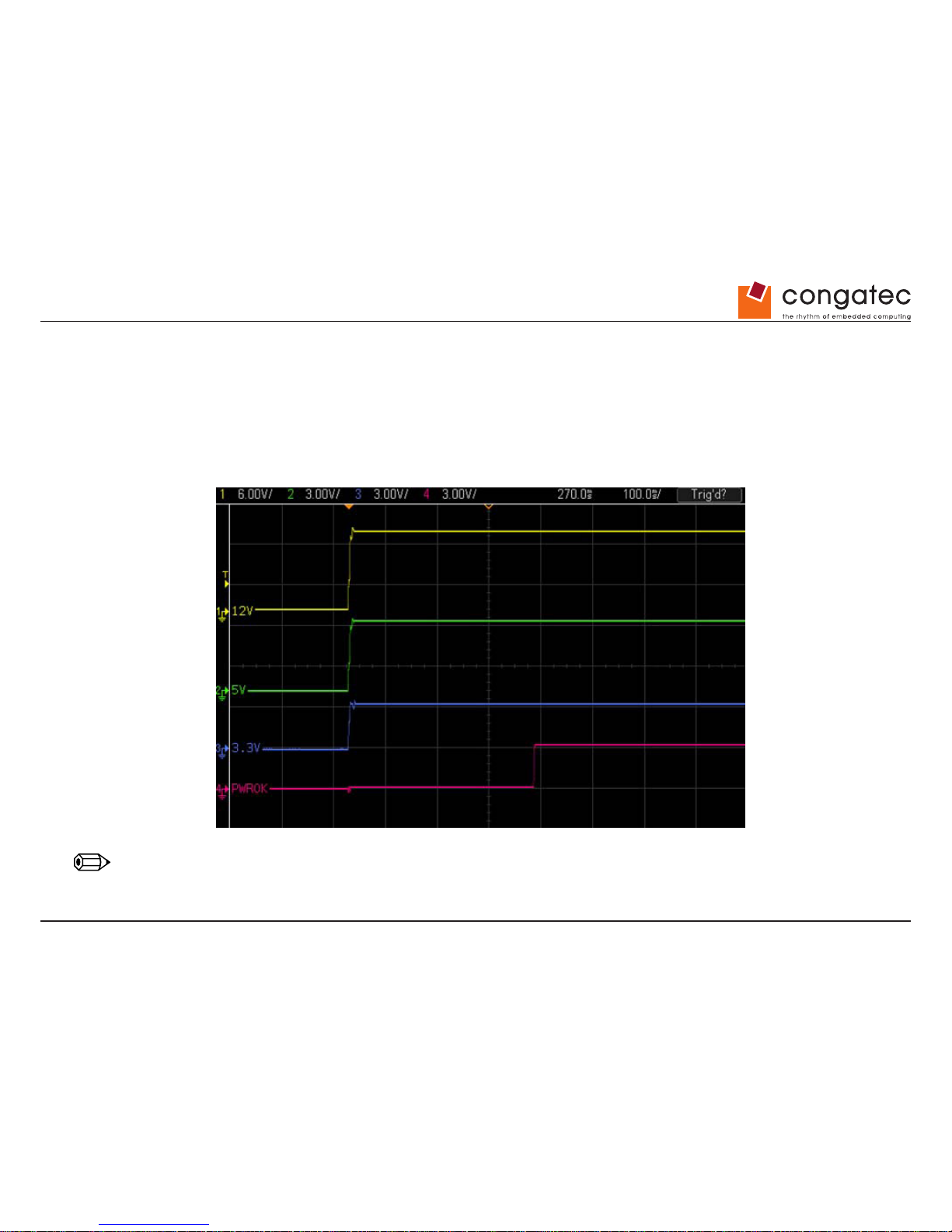
PWR_OK
Power OK from main power supply or carrier board voltage regulator circuitry. A high value indicates that the power is good and the module
can start its onboard power sequencing. Carrier board hardware must drive this signal low until all power rails and clocks are stable. Releasing
PWR_OK too early or not driving it low at all can cause numerous boot up problems. It is a good design practice to delay the PWR_OK signal
a little (typically 100ms) after all carrier board power rails are up, to ensure a stable system. See screenshot below.
Note
The module is kept in reset as long as the PWR_OK is driven by carrier board hardware.
Page 27
Copyright © 2012 congatec AG TCEDm10 27/94
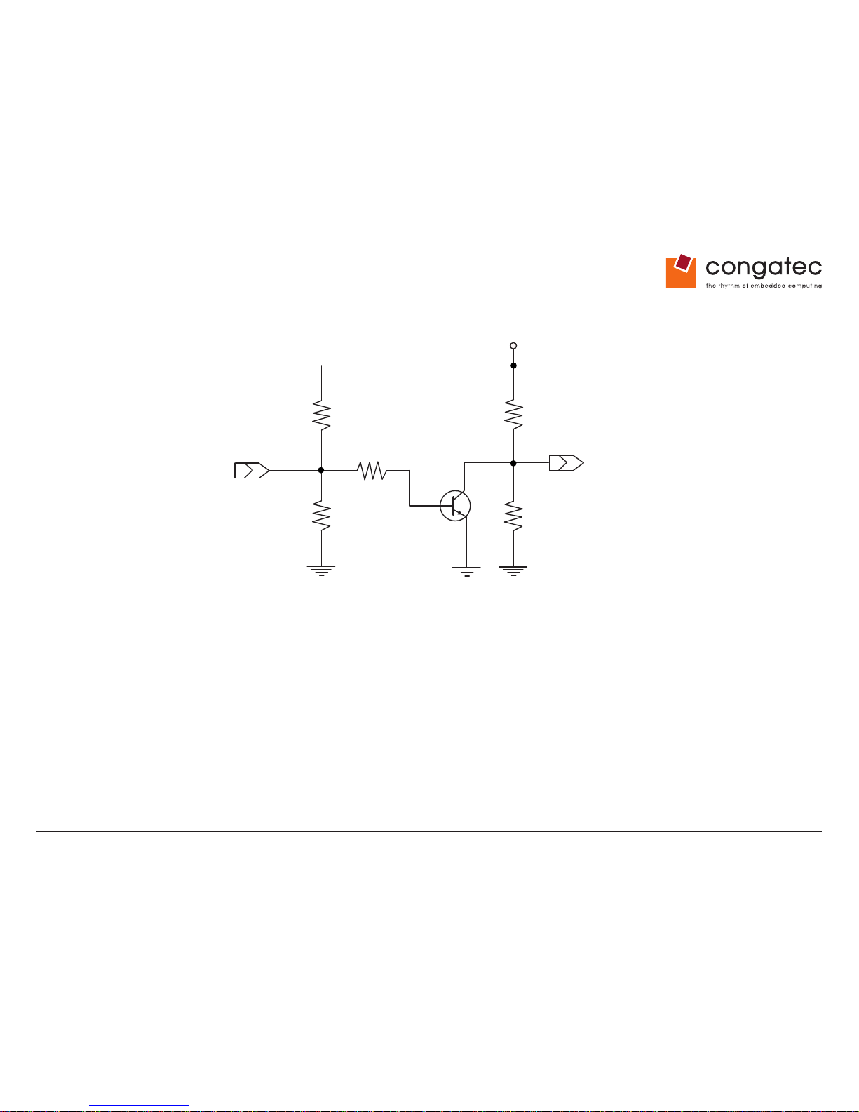
The conga-TCA PWR_OK input circuitry is implemented as shown below:
The voltage divider ensures that the input complies with 3.3V CMOS characteristic and also allows for carrier board designs that are not driving
PWR_OK. Although the PWR_OK input is not mandatory for the onboard power-up sequencing, it is strongly recommended that the carrier
board hardware drives the signal low until it is safe to let the module boot-up.
When considering the above shown voltage divider circuitry and the transistor stage, the voltage measured at the PWR_OK input pin may be
only around 0.8V when the 12V is applied to the module. Actively driving PWR_OK high is compliant to the COM Express specication but this
can cause back driving. Therefore, congatec recommends driving the PWR_OK low to keep the module in reset and tri-state PWR_OK when
the carrier board hardware is ready to boot.
The three typical usage scenarios for a carrier board design are:
• Connect PWR_OK to the “power good” signal of an ATX type power supply.
• Connect PWR_OK to the last voltage regulator in the chain on the carrier board.
• Simply pull PWR_OK with a 1k resistor to the carrier board 3.3V power rail.
With this solution, it must be ensured that by the time the 3.3V is up, all carrier board hardware is fully powered and all clocks are stable.
To Module Power Logic
PWR_OK
R5
R1%47k5S02
TB
TBC847
R4
R1%100kS02
+V12.0_S0
R13
R1%1k00S02
R1
R1%47k5S02
R2
R1%20k0S02
Page 28
Copyright © 2012 congatec AG TCEDm10 28/94
The conga-TCA provides support for controlling ATX-style power supplies. When not using an ATX power supply then the conga-TCA’s pins
SUS_S3/PS_ON, 5V_SB, and PWRBTN# should be left unconnected.
SUS_S3#/PS_ON#
The SUS_S3#/PS_ON# (pin A15 on the A-B connector) signal is an active-low output that can be used to turn on the main outputs of an ATXstyle power supply. In order to accomplish this the signal must be inverted with an inverter/transistor that is supplied by standby voltage and
is located on the carrier board.
PWRBTN#
When using ATX-style power supplies PWRBTN# (pin B12 on the A-B connector) is used to connect to a momentary-contact, active-low
debounced push-button input while the other terminal on the push-button must be connected to ground. This signal is internally pulled up to
3V_SB using a 10k resistor. When PWRBTN# is asserted it indicates that an operator wants to turn the power on or off. The response to this
signal from the system may vary as a result of modications made in BIOS settings or by system software.
Power Supply Implementation Guidelines
12 volt input power is the sole operational power source for the conga-TCA. The remaining necessary voltages are internally generated on the
module using onboard voltage regulators. A carrier board designer should be aware of the following important information when designing a
power supply for a conga-TCA application:
• It has also been noticed that on some occasions, problems occur when using a 12V power supply that produces non monotonic voltage
when powered up. The problem is that some internal circuits on the module (e.g. clock-generator chips) will generate their own reset signals
when the supply voltage exceeds a certain voltage threshold. A voltage dip after passing this threshold may lead to these circuits becoming
confused resulting in a malfunction. It must be mentioned that this problem is quite rare but has been observed in some mobile power supply
applications. The best way to ensure that this problem is not encountered is to observe the power supply rise waveform through the use
of an oscilloscope to determine if the rise is indeed monotonic and does not have any dips. This should be done during the power supply
qualication phase therefore ensuring that the above mentioned problem doesn’t arise in the application. For more information about this
issue visit www.formfactors.org and view page 25 gure 7 of the document “ATX12V Power Supply Design Guide V2.2”.
4.1.15 Power Management
ACPI 3.0 compliant with battery support. Also supports Suspend to RAM (S3).
Page 29
Copyright © 2012 congatec AG TCEDm10 29/94
4.2 Secondary Connector Rows C and D
The following subsystems can be found on the secondary connector rows C and D.
4.2.1 USB 3.0
The conga-TCA offers two USB 3.0 ports with the integration of a USB 3.0 xHCI compliant host controller (Texas Instrument TUSB7320). This
controller is implemented through the use of one PCI Express™ lane and provides SuperSpeed, high-speed, full-speed and low-speed trafc
on the bus.
Note
The USB 3.0 is an optional feature.
4.2.2 HDMI
The Intel
®
Atom™ D2000/N2000 series processors on the conga-TCA supports integrated HDMI, which is multiplexed onto the Digital Display
Interface (DDI) of the COM Express connector. The processor provides two ports capable of supporting HDMI. See section 7.5 of this document
for more information about enabling HDMI peripherals.
4.2.3 DisplayPort (DP)
The conga-TCA offers two DP ports, each capable of supporting link-speeds of 1.62 Gbps and 2.7 Gbps on 1, 2 or 4 data lanes. The DP is
multiplexed onto the Digital Display Interface (DDI) of the COM Express connector. The DisplayPort specication is a VESA standard aimed at
consolidating internal and external connection methods to reduce device complexity, supporting key cross industry applications, and providing
performance scalability to enable the next generation of displays. The Intel® Atom™ D2000/N2000 series processors can support a maximum
of 2 DP ports simultaneously. See section 7.5 of this document for more information about enabling DisplayPort peripherals.
Page 30
Copyright © 2012 congatec AG TCEDm10 30/94
5 Additional Features
5.1 congatec Board Controller (cBC)
The conga-TCA is equipped with a STMicroelectronics STM32 microcontroller. This onboard microcontroller plays an important role for most of
the congatec embedded/industrial PC features. It fully isolates some of the embedded features such as system monitoring or the I²C bus from
the x86 core architecture, which results in higher embedded feature performance and more reliability, even when the x86 processor is in a low
power mode. It also ensures that the congatec embedded feature set is fully compatible amongst all congatec modules.
5.2 Board Information
The cBC provides a rich data-set of manufacturing and board information such as serial number, EAN number, hardware and rmware
revisions, and so on. It also keeps track of dynamically changing data like runtime meter and boot counter.
5.3 Watchdog
The conga-TCA is equipped with a multi stage watchdog solution that is triggered by software. The COM Express™ Specication does
not provide support for external hardware triggering of the Watchdog, which means the conga-TCA does not support external hardware
triggering. For more information about the Watchdog feature see the BIOS setup description section 9.4.2 of this document and application
note AN3_Watchdog.pdf on the congatec AG website at www.congatec.com.
Note
The conga-TCA module does not support the watchdog NMI mode. COM Express type 6 modules do not support the PCI bus and therefore the
PCI_SERR# signal is not available. There is no way to drive a NMI to the processor without the presence of the PCI_SERR# PCI bus signal.
5.4 I2C Bus
The conga-TCA offers support for the frequently used I2C bus. Thanks to the I
2
C host controller in the cBC the I
2
C bus is multimaster capable
and runs at fast mode.
Page 31
Copyright © 2012 congatec AG TCEDm10 31/94
5.5 Power Loss Control
The cBC has full control of the power-up of the module and therefore can be used to specify the behaviour of the system after a AC power loss
condition. Supported modes are “Always On”, “Remain Off” and “Last State”.
5.6 Embedded BIOS
The conga-TCA is equipped with congatec Embedded BIOS, which is based on American Megatrends Inc. Aptio UEFI rmware. These are the
most important embedded PC features:
5.6.1 CMOS Backup in Non Volatile Memory
A copy of the CMOS memory (SRAM) is stored in the BIOS ash device. This prevents the system from not booting up with the correct system
conguration if the backup battery (RTC battery) has failed. Additionally, it provides the ability to create systems that do not require a CMOS
backup battery.
5.6.2 OEM CMOS Default Settings and OEM BIOS Logo
This feature allows system designers to create and store their own CMOS default conguration and BIOS logo (splash screen) within the BIOS
ash device. Customized BIOS development by congatec for these changes is no longer necessary because customers can easily do these
changes by themselves using the congatec system utility CGUITL.
5.6.3 OEM BIOS Code
With the congatec embedded BIOS it is even possible for system designers to add their own code to the BIOS POST process. Except for
custom specic code, this feature can also be used to support Win XP SLP installation, Window 7 SLIC table, verb tables for HDA codecs, rare
graphic modes and Super I/O controllers.
For more information about customizing the congatec embedded BIOS refer to the congatec System Utility user’s guide, which is called
CGUTLm1x.pdf and can be found on the congatec AG website at www.congatec.com or contact congatec technical support.
Page 32
Copyright © 2012 congatec AG TCEDm10 32/94
5.6.4 congatec Battery Management Interface
In order to facilitate the development of battery powered mobile systems based on embedded modules, congatec AG has dened an interface
for the exchange of data between a CPU module (using an ACPI operating system) and a Smart Battery system. A system developed according
to the congatec Battery Management Interface Specication can provide the battery management functions supported by an ACPI capable
operating system (e.g. charge state of the battery, information about the battery, alarms/events for certain battery states, ...) without the need
for any additional modications to the system BIOS.
The conga-TCA BIOS fully supports this interface. For more information about this subject visit the congatec website and view the following
documents:
• congatec Battery Management Interface Specication
• Battery System Design Guide
• conga-SBM3 User’s Guide
5.6.5 API Support (CGOS/EAPI)
In order to benet from the above mentioned non-industry standard feature set, congatec provides an API that allows application software
developers to easily integrate all these features into their code. The CGOS API (congatec Operating System Application Programming
Interface) is the congatec proprietary API that is available for all commonly used Operating Systems such as Win32, Win64, Win CE, Linux.
The architecture of the CGOS API driver provides the ability to write application software that runs unmodied on all congatec CPU modules.
All the hardware related code is contained within the congatec embedded BIOS on the module. See section 1.1 of the CGOS API software
developers guide, which is available on the congatec website .
Other COM (Computer on Modules) vendors offer similar driver solutions for these kind of embedded PC features, which are by nature
proprietary. All the API solutions that can be found on the market are not compatible to each other. As a result, writing application software that
can run on more than one vendor’s COM is not so easy. Customers have to change their application software when switching to another COM
vendor. EAPI (Embedded Application Programming Interface) is a programming interface dened by the PICMG that addresses this problem.
With this unied API, it is now possible to run the same application on all vendor’s COMs that offer EAPI driver support. Contact congatec
technical support for more information about EAPI.
Page 33
Copyright © 2012 congatec AG TCEDm10 33/94
5.7 Security Features
The conga-TCA can be equipped optionally with a “Trusted Platform Module“ (TPM 1.2). This TPM 1.2 includes coprocessors to calculate
efcient hash and RSA algorithms with key lengths up to 2,048 bits as well as a real random number generator. Security sensitive applications
like gaming and e-commerce will benet also with improved authentication, integrity and condence levels.
5.8 Suspend to Ram
The Suspend to RAM feature is available on the conga-TCA.
Page 34
Copyright © 2012 congatec AG TCEDm10 34/94
6 conga Tech Notes
The conga-TCA has some technological features that require additional explanation. The following section will give the reader a better
understanding of some of these features. This information will also help to gain a better understanding of the information found in the System
Resources section of this user’s guide as well as some of the setup nodes found in the BIOS Setup Program description section.
6.1 Intel® Matrix Storage Technology
The Intel
®
CG82NM10 (NM10) PCH provides support for Intel
®
Matrix Storage Technology, allowing AHCI functionality.
6.1.1 AHCI
The Intel
®
CG82NM10 (NM10) PCH provides hardware support for Advanced Host Controller Interface (AHCI), a new programming interface for
SATA host controllers. Platforms supporting AHCI may take advantage of performance features such as no master/slave designation for SATA
devices (each device is treated as a master) and hardware-assisted native command queuing. AHCI also provides usability enhancements
such as Hot-Plug.
6.2 Intel® Processor Features
6.2.1 Thermal Monitor and Catastrophic Thermal Protection
Intel
®
Atom™ D2000/N2000 series processors have a thermal monitor feature that helps to control the processor temperature. The integrated
TCC (Thermal Control Circuit) activates if the processor silicon reaches its maximum operating temperature. The activation temperature, that
the Intel
®
Thermal Monitor uses to activate the TCC, cannot be congured by the user nor is it software visible.
The Thermal Monitor can control the processor temperature through the use of two different methods dened as TM1 and TM2. TM1 method
consists of the modulation (starting and stopping) of the processor clocks at a 50% duty cycle. The TM2 method initiates an Enhanced Intel
Speedstep transition to the lowest performance state once the processor silicon reaches the maximum operating temperature.
Note
The maximum operating temperature for Intel
®
Atom™ D2000/N2000 series processors is 100°C.
Two modes are supported by the Thermal Monitor to activate the TCC. They are called Automatic and On-Demand. No additional hardware,
software, or handling routines are necessary when using Automatic Mode.
Page 35
Copyright © 2012 congatec AG TCEDm10
35/94
Note
T o ensure that the TCC is active for only short periods of time, thus reducing the impact on processor performance to a minimum, it is necessary
to have a properly designed thermal solution. The Intel
®
Atom™ D2000/N2000 series processor ’s respective datasheet can provide you with
more information about this subject.
THERMTRIP# signal is used by Intel
®
’s Atom™ D2000/N2000 series processors for catastrophic thermal protection. If the processor ’s silicon
reaches a temperature of approximately 125°C then the processor signal THERMTRIP# will go active and the system will automatically shut
down to prevent any damage to the processor as a result of overheating. The THERMTRIP# signal activation is completely independent from
processor activity and therefore does not produce any bus cycles.
Note
In order for THERMTRIP# to be able to automatically switch off the system, it is necessary to use an ATX style power supply.
6.2.2 Processor Performance Control
Intel
®
Atom™ D2000/N2000 series processors found on the conga-TCA run at different voltage/frequency states (performance states), which
is referred to as Enhanced Intel® SpeedStep
®
technology (EIST). Operating systems that support performance control take advantage of
microprocessors that use several different performance states in order to efciently operate the processor when it’s not being fully utilized.
The operating system will determine the necessary performance state that the processor should run at so that the optimal balance between
performance and power consumption can be achieved during runtime.
The Windows family of operating systems links its processor performance control policy to the power scheme setting. You must ensure that
your power scheme setting you choose has the ability to support Enhanced Intel
®
SpeedStep® technology.
6.3 Thermal Management
ACPI is responsible for allowing the operating system to play an important part in the system’s thermal management. This results in the
operating system having the ability to take control of the operating environment by implementing cooling decisions according to the demands
put on the CPU by the application.
The conga-TCA ACPI thermal solution offers three different cooling policies.
• Passive Cooling
When the temperature in the thermal zone must be reduced, the operating system can decrease the power consumption of the processor by
throttling the processor clock. One of the advantages of this cooling policy is that passive cooling devices (in this case the processor) do not
Page 36
Copyright © 2012 congatec AG TCEDm10
36/94
produce any noise. Use the “passive cooling trip point” setup node in the BIOS setup program to determine the temperature threshold that the
operating system will use to start or stop the passive cooling procedure.
• Active Cooling
During this cooling policy the operating system is turning the fan on/off. Although active cooling devices consume power and produce noise,
they also have the ability to cool the thermal zone without having to reduce the overall system performance. Use the “active cooling trip point”
setup node in the BIOS setup program to determine the temperature threshold that the operating system will use to start the active cooling
device. It is stopped again when the temperature goes below the threshold (4°C hysteresis).
• Critical Trip Point
If the temperature in the thermal zone reaches a critical point then the operating system will perform a system shut down in an orderly fashion
in order to ensure that there is no damage done to the system as result of high temperatures. Use the “critical trip point” setup node in the BIOS
setup program to determine the temperature threshold that the operating system will use to shut down the system.
Note
The end user must determine the cooling preferences for the system by using the setup nodes in the BIOS setup program to establish the
appropriate trip points.
If passive cooling is activated and the processor temperature is above the trip point the processor clock is throttled according to the formula
below.
∆P[%] = TC1(T
n-Tn-1
) + TC2(Tn-Tt)
• ∆P is the performance delta
• Tt is the target temperature = critical trip point
• The two coefcients TC1 and TC2 and the sampling period TSP are hardware dependent constants. These constants are set to xed values
for the conga-TCA:
• TC1= 1
• TC2= 5
• TSP= 5 seconds
See section 12 of the ACPI Specication 2.0 C for more information about passive cooling.
Page 37
Copyright © 2012 congatec AG TCEDm10 37/94
6.4 ACPI Suspend Modes and Resume Events
conga-TCA supports S3 (STR= Suspend to RAM). For more information about S3 wake events see section 9.4.5 “ACPI Submenu”.
S4 (Suspend to Disk) is not supported by the BIOS (S4_BIOS) but it is supported by the following operating systems (S4_OS= Hibernate):
• Windows 7, Windows Vista, Linux, Windows XP and Windows 2K
This table lists the “Wake Events” that resume the system from S3 unless otherwise stated in the “Conditions/Remarks” column:
Wake Event Conditions/Remarks
Power Button Wakes unconditionally from S3-S5.
Onboard LAN Event Device driver must be congured for Wake On LAN support.
SMBALERT# Wakes unconditionally from S3-S5.
PCI Express WAKE# Wakes unconditionally from S3-S5.
USB Mouse/Keyboard Event When Standby mode is set to S3, the following must be done for a USB Mouse/Keyboard Event to be used as a Wake Event.
USB Hardware must be powered by standby power source.
Set USB Device Wakeup from S3/S4 to ENABLED in the ACPI setup menu (if setup node is available in BIOS setup program).
Under Windows XP add following registry entries:
Add this key:
HKEY_LOCAL_MACHINE\SYSTEM\CurrentControlSet\Services\usb
Under this key add the following value:
“USBBIOSx“=DWORD:00000000
Note that Windows XP disables USB wakeup from S3, so this entry has to be added to re-enable it.
Congure USB keyboard/mouse to be able to wake up the system:
In Device Manager look for the keyboard/mouse devices. Go to the Power Management tab and check ‘Allow this device to bring the
computer out of standby’.
Note: When the standby state is set to S3 in the ACPI setup menu, the power management tab for USB keyboard /mouse devices only
becomes available after adding the above registry entry and rebooting to allow the registry changes to take affect.
RTC Alarm Activate and congure Resume On RTC Alarm in the Power setup menu. Only available in S5.
Watchdog Power Button Event Wakes unconditionally from S3-S5.
Page 38
Copyright © 2012 congatec AG TCEDm10 38/94
6.5 USB 2.0 EHCI Host Controller Support
The Intel
®
CG82NM10 (NM10) PCH supports up to eight USB ports. The 8 available USB ports are shared between 1 EHCI host controller
and the 4 UHCI host controllers.
The muxing between the UHCI and EHCI host controllers is performed by the port-routing logic integrated into the EHC functionality. If a device
not capable of USB 2.0 high-speed signalling is connected or if the EHCI software drivers are not present,then the UHCI controller owns
the port. Owning the port means that the differential output is driven by the owner and the input stream is only visible to the owner. The host
controller that is not the owner of the port internally sees a disconnected port.
The Intel
®
CG82NM10 (NM10) PCH allows the USB Debug Port trafc to be routed in and out of Port 0. When in this mode, the Enhanced Host
controller is the owner of Port 0.
Routing Diagram
UHCI #3
(D29:F3)
Debug
Port
Enhanced Host Controller Logic
UHCI #2
(D29:F2)
UHCI #1
(D29:F1)
UHCI #0
(D29:F0)
Port 7
Port 6
Port 5
Port 4
Port 3
Port 2
Port 1
Port 0
Page 39
Copyright © 2012 congatec AG TCEDm10 39/94
7 Signal Descriptions and Pinout Tables
The following section describes the signals found on COM Express™ Type VI connectors used for congatec AG modules. The pinout of the
modules complies with COM Express Type 6.0 Rev. 2.1.
Table 2 describes the terminology used in this section for the Signal Description tables. The PU/PD column indicates if a COM Express™
module pull-up or pull-down resistor has been used, if the eld entry area in this column for the signal is empty, then no pull-up or pull-down
resistor has been implemented by congatec.
The “#” symbol at the end of the signal name indicates that the active or asserted state occurs when the signal is at a low voltage level. When
“#” is not present, the signal is asserted when at a high voltage level.
Note
The Signal Description tables do not list internal pull-ups or pull-downs implemented by the chip vendors, only pull-ups or pull-downs implemented
by congatec are listed. For information about the internal pull-ups or pull-downs implemented by the chip vendors, refer to the respective chip’s
datasheet.
Table 2 Signal Tables Terminology Descriptions
Term Description
PU congatec implemented pull-up resistor
PD congatec implemented pull-down resistor
I/O 3.3V Bi-directional signal 3.3V tolerant
I/O 5V Bi-directional signal 5V tolerant
I 3.3V Input 3.3V tolerant
I 5V Input 5V tolerant
I/O 3.3VSB Input 3.3V tolerant active in standby state
O 3.3V Output 3.3V signal level
O 5V Output 5V signal level
OD Open drain output
P Power Input/Output
DDC Display Data Channel
PCIE In compliance with PCI Express Base Specication, Revision 1.0a
PEG PCI Express Graphics
SATA In compliance with Serial ATA specication, Revision 3.0.
REF Reference voltage output. May be sourced from a module power plane.
PDS Pull-down strap. A module output pin that is either tied to GND or is not connected. Used to signal
module capabilities (pinout type) to the Carrier Board.
Page 40
Copyright © 2012 congatec AG TCEDm10 40/94
7.1 A-B Connector Signal Descriptions
Table 3 Intel
®
High Denition Audio Link Signals Descriptions
Signal Pin # Description I/O PU/PD Comment
AC/HDA_RST# A30 Intel® High Denition Audio Reset: This signal is the master hardware reset
to external codec(s).
O 3.3VSB AC’97 codecs are not supported.
AC/HDA_SYNC A29 Intel
®
High Denition Audio Sync: This signal is a 48 kHz xed rate sample
sync to the codec(s). It is also used to encode the stream number.
O 3.3V AC’97 codecs are not supported.
AC/HDA_SYNC is a boot strap signal
(see note below)
AC/HDA_BITCLK A32 Intel
®
High Denition Audio Bit Clock Output: This signal is a 24.000MHz
serial data clock generated by the Intel
®
High Denition Audio controller.
O 3.3V AC’97 codecs are not supported.
AC/HDA_SDOUT A33 Intel
®
High Denition Audio Serial Data Out: This signal is the serial TDM
data output to the codec(s). This serial output is double-pumped for a bit rate
of 48 Mb/s for Intel® High Denition Audio.
O 3.3V AC’97 codecs are not supported.
AC/HDA_SDOUT is a boot strap signal
(see note below)
AC/HDA_SDIN[1:0] B29-B30 Intel
®
High Denition Audio Serial Data In [1:0]: These signals are serial
TDM data inputs from the two codecs. The serial input is single-pumped for a
bit rate of 24 Mb/s for Intel® High Denition Audio.
I 3.3V AC’97 codecs are not supported.
AC/HDA_SDIN2 is not supported
Note
Some signals have special functionality during the reset process. They may bootstrap some basic important functions of the module.
For more information refer to section 7.5 of this user’s guide.
Page 41
Copyright © 2012 congatec AG TCEDm10 41/94
Table 4 Gigabit Ethernet Signal Descriptions
Gigabit Ethernet Pin # Description I/O PU/PD Comment
GBE0_MDI0+
GBE0_MDI0-
GBE0_MDI1+
GBE0_MDI1-
GBE0_MDI2+
GBE0_MDI2-
GBE0_MDI3+
GBE0_MDI3-
A13
A12
A10
A9
A7
A6
A3
A2
Gigabit Ethernet Controller 0: Media Dependent Interface Differential Pairs 0, 1, 2, 3. The MDI can operate
in 1000, 100, and 10Mbit/sec modes. Some pairs are unused in some modes according to the following:
I/O Analog Twisted pair
signals for
external
transformer.
1000 100 10
MDI[0]+/- B1_DA+/- TX+/- TX+/MDI[1]+/- B1_DB+/- RX+/- RX+/-
MDI[2]+/- B1_DC+/-
MDI[3]+/- B1_DD+/-
GBE0_ACT# B2 Gigabit Ethernet Controller 0 activity indicator, active low. O 3.3VSB
GBE0_LINK# A8 Gigabit Ethernet Controller 0 link indicator, active low. O 3.3VSB
GBE0_LINK100# A4 Gigabit Ethernet Controller 0 100Mbit/sec link indicator, active low. O 3.3VSB
GBE0_LINK1000# A5 Gigabit Ethernet Controller 0 1000Mbit/sec link indicator, active low. O 3.3VSB
GBE0_CTREF A14 Reference voltage for Carrier Board Ethernet channel 0 magnetics center tap. The reference voltage is
determined by the requirements of the module PHY and may be as low as 0V and as high as 3.3V. The
reference voltage output shall be current limited on the module. In the case in which the reference is shorted
to ground, the current shall be limited to 250mA or less.
Not connected
Note
The GBE0_LINK# output is only active during a 100Mbit or 1Gbit connection, it is not active during a 10Mbit connection. This is a limitation
of Ethernet controller since it only has 3 LED outputs, ACT#, LINK100# and LINK1000#. The GBE0_LINK# signal is a logic AND of the
GBE0_LINK100# and GBE0_LINK1000# signals on the conga-TCA module.
Page 42
Copyright © 2012 congatec AG TCEDm10 42/94
Table 5 Serial ATA Signal Descriptions
Signal Pin # Description I/O PU/PD Comment
SATA0_RX+
SATA0_RX-
A19
A20
Serial ATA channel 0, Receive Input differential pair. I SATA Supports Serial ATA II specication, up to 3 Gb/s
SATA0_TX+
SATA0_TX-
A16
A17
Serial ATA channel 0, Transmit Output differential pair. O SATA Supports Serial ATA II specication, up to 3 Gb/s
SATA1_RX+
SATA1_RX-
B19
B20
Serial ATA channel 1, Receive Input differential pair. I SATA Supports Serial ATA II specication, up to 3 Gb/s
SATA1_TX+
SATA1_TX-
B16
B17
Serial ATA channel 1, Transmit Output differential pair. O SATA Supports Serial ATA II specication, up to 3 Gb/s
SATA2_RX+
SATA2_RX-
A25
A26
Serial ATA channel 2, Receive Input differential pair. I SATA Not supported
SATA2_TX+
SATA2_TX-
A22
A23
Serial ATA channel 2, Transmit Output differential pair. O SATA Not supported
SATA3_RX+
SATA3_RX-
B25
B26
Serial ATA channel 3, Receive Input differential pair. I SATA Not supported
SATA3_TX+
SATA3_TX-
B22
B23
Serial ATA channel 3, Transmit Output differential pair. O SATA Not supported
(S)ATA_ACT# A28 ATA (parallel and serial) or SAS activity indicator, active low. I/O 3.3v
Page 43
Copyright © 2012 congatec AG TCEDm10 43/94
Table 6 PCI Express Signal Descriptions (general purpose)
Signal Pin # Description I/O PU/PD Comment
PCIE_RX0+
PCIE_RX0-
B68
B69
PCI Express channel 0, Receive Input differential pair. I PCIE Supports PCI Express Base Specication, Revision 1.0a
PCIE_TX0+
PCIE_TX0-
A68
A69
PCI Express channel 0, Transmit Output differential pair. O PCIE Supports PCI Express Base Specication, Revision 1.0a
PCIE_RX1+
PCIE_RX1-
B64
B65
PCI Express channel 1, Receive Input differential pair. I PCIE Supports PCI Express Base Specication, Revision 1.0a
PCIE_TX1+
PCIE_TX1-
A64
A65
PCI Express channel 1, Transmit Output differential pair. O PCIE Supports PCI Express Base Specication, Revision 1.0a
PCIE_RX2+
PCIE_RX2-
B61
B62
PCI Express channel 2, Receive Input differential pair. I PCIE Supports PCI Express Base Specication, Revision 1.0a
PCIE_TX2+
PCIE_TX2-
A61
A62
PCI Express channel 2, Transmit Output differential pair. O PCIE Supports PCI Express Base Specication, Revision 1.0a
PCIE_RX3+
PCIE_RX3-
B58
B59
PCI Express channel 3, Receive Input differential pair. I PCIE Supports PCI Express Base Specication, Revision 1.0a
PCIE_TX3+
PCIE_TX3-
A58
A59
PCI Express channel 3, Transmit Output differential pair. O PCIE Supports PCI Express Base Specication, Revision 1.0a
PCIE_RX4+
PCIE_RX4-
B55
B56
PCI Express channel 4, Receive Input differential pair. I PCIE Supports PCI Express Base Specication, Revision 1.0a
Only available on modules without USB 3.0 support
PCIE_TX4+
PCIE_TX4-
A55
A56
PCI Express channel 4, Transmit Output differential pair. O PCIE Supports PCI Express Base Specication, Revision 1.0a.
Only available on modules without USB 3.0 support
PCIE_RX5+
PCIE_RX5-
B52
B53
PCI Express channel 5, Receive Input differential pair. I PCIE Not supported
PCIE_TX5+
PCIE_TX5-
A52
A53
PCI Express channel 5, Transmit Output differential pair. O PCIE Not supported
PCIE_CLK_REF+
PCIE_CLK_REF-
A88
A89
PCI Express Reference Clock output for all PCI Express
and PCI Express Graphics Lanes.
O PCIE A PCI Express compliant clock buffer chip must be used on the
carrier board if more than one PCI Express device is designed
in.
Page 44
Copyright © 2012 congatec AG TCEDm10 44/94
Table 7 ExpressCard Support Pins Descriptions
Signal Pin # Description I/O PU/PD Comment
EXCD0_CPPE# A49 ExpressCard 0 capable card request. I 3.3V PU 10k 3.3V
EXCD0_PERST# A48 ExpressCard 0 Reset O 3.3V PD 2.2k EXCDO_PERST# is a bootstrap signal
EXCD1_CPPE# B48 ExpressCard 1 capable card request I 3.3V PU 10k 3.3V
EXCD1_PERST# B47 ExpressCard 1 Reset O 3.3V
Table 8 LPC Signal Descriptions
Signal Pin # Description I/O PU/PD Comment
LPC_AD[0:3] B4-B7 LPC multiplexed address, command and data bus I/O 3.3V
LPC_FRAME# B3 LPC frame indicates the start of an LPC cycle O 3.3V
LPC_DRQ[0:1]# B8-B9 LPC serial DMA request I 3.3V
LPC_SERIRQ A50 LPC serial interrupt I/O OD 3.3V PU 4.99k 3.3V
LPC_CLK B10 LPC clock output - 33MHz nominal O 3.3V PD 10k LPC_CLK is a bootstrap signal
Note
Some signals have special functionality during the reset process. They may bootstrap some basic important functions of the module.
For more information refer to section 7.5 of this user’s guide.
Page 45
Copyright © 2012 congatec AG TCEDm10
45/94
Table 9 USB Signal Descriptions
Signal Pin # Description I/O PU/PD Comment
USB0+ A46 USB Port 0, data + or D+ I/O USB 2.0 compliant. Backwards compatible to USB 1.1
USB0- A45 USB Port 0, data - or D- I/O USB 2.0 compliant. Backwards compatible to USB 1.1
USB1+ B46 USB Port 1, data + or D+ I/O USB 2.0 compliant. Backwards compatible to USB 1.1
USB1- B45 USB Port 1, data - or D- I/O USB 2.0 compliant. Backwards compatible to USB 1.1
USB2+ A43 USB Port 2, data + or D+ I/O USB 2.0 compliant. Backwards compatible to USB 1.1
USB2- A42 USB Port 2, data - or D- I/O USB 2.0 compliant. Backwards compatible to USB 1.1
USB3+ B43 USB Port 3, data + or D+ I/O USB 2.0 compliant. Backwards compatible to USB 1.1
USB3- B42 USB Port 3, data - or D- I/O USB 2.0 compliant. Backwards compatible to USB 1.1
USB4+ A40 USB Port 4, data + or D+ I/O USB 2.0 compliant. Backwards compatible to USB 1.1
USB4- A39 USB Port 4, data - or D- I/O USB 2.0 compliant. Backwards compatible to USB 1.1
USB5+ B40 USB Port 5, data + or D+ I/O USB 2.0 compliant. Backwards compatible to USB 1.1
USB5- B39 USB Port 5, data - or D- I/O USB 2.0 compliant. Backwards compatible to USB 1.1
USB6+ A37 USB Port 6, data + or D+ I/O USB 2.0 compliant. Backwards compatible to USB 1.1
USB6- A36 USB Port 6, data - or D- I/O USB 2.0 compliant. Backwards compatible to USB 1.1
USB7+ B37 USB Port 7, data + or D+ I/O USB 2.0 compliant. Backwards compatible to USB 1.1
USB7- B36 USB Port 7, data - or D- I/O USB 2.0 compliant. Backwards compatible to USB 1.1
USB_0_1_OC# B44 USB over-current sense, USB ports 0 and 1. A pull-up for this line shall
be present on the module. An open drain driver from a USB current
monitor on the carrier board may drive this line low.
I
3.3VSB
PU 10k
3.3VSB
Do not pull this line high on the carrier board.
USB_2_3_OC# A44 USB over-current sense, USB ports 2 and 3. A pull-up for this line shall
be present on the module. An open drain driver from a USB current
monitor on the carrier board may drive this line low. .
I
3.3VSB
PU 10k
3.3VSB
Do not pull this line high on the carrier board.
USB_4_5_OC# B38 USB over-current sense, USB ports 4 and 5. A pull-up for this line shall
be present on the module. An open drain driver from a USB current
monitor on the carrier board may drive this line low.
I
3.3VSB
PU 10k
3.3VSB
Do not pull this line high on the carrier board.
USB_6_7_OC# A38 USB over-current sense, USB ports 6 and 7. A pull-up for this line shall
be present on the module. An open drain driver from a USB current
monitor on the carrier board may drive this line low.
I
3.3VSB
PU 10k
3.3VSB
Do not pull this line high on the carrier board.
Table 10 CRT Signal Descriptions
Signal Pin # Description I/O PU/PD Comment
VGA_RED B89 Red for monitor. Analog DAC output, designed to drive a 37.5-Ohm equivalent load. O Analog PD 150R Analog output
VGA_GRN B91 Green for monitor. Analog DAC output, designed to drive a 37.5-Ohm equivalent load. O Analog PD 150R Analog output
VGA_BLU B92 Blue for monitor. Analog DAC output, designed to drive a 37.5-Ohm equivalent load. O Analog PD 150R Analog output
VGA_HSYNC B93 Horizontal sync output to VGA monitor O 3.3V
VGA_VSYNC B94 Vertical sync output to VGA monitor O 3.3V
VGA_I2C_CK B95 DDC clock line (I²C port dedicated to identify VGA monitor capabilities) I/O OD 5V PU 2k2 3.3V
VGA_I2C_DAT B96 DDC data line. I/O OD 5V PU 2k2 3.3V
Page 46
Copyright © 2012 congatec AG TCEDm10
46/94
Table 11 LVDS Signal Descriptions
Signal Pin # Description I/O PU/PD Comment
LVDS_A0+
LVDS_A0-
LVDS_A1+
LVDS_A1-
LVDS_A2+
LVDS_A2-
LVDS_A3+
LVDS_A3-
A71
A72
A73
A74
A75
A76
A78
A79
LVDS Channel A differential pairs O LVDS
LVDS_A_CK+
LVDS_A_CK-
A81
A82
LVDS Channel A differential clock O LVDS
LVDS_B0+
LVDS_B0-
LVDS_B1+
LVDS_B1-
LVDS_B2+
LVDS_B2-
LVDS_B3+
LVDS_B3-
B71
B72
B73
B74
B75
B76
B77
B78
LVDS Channel B differential pairs O LVDS Not suppported
LVDS_B_CK+
LVDS_B_CK-
B81
B82
LVDS Channel B differential clock O LVDS Not supported
LVDS_VDD_EN A77 LVDS panel power enable O 3.3V PD 10k
LVDS_BKLT_EN B79 LVDS panel backlight enable O 3.3V PD 10k
LVDS_BKLT_CTRL B83 LVDS panel backlight brightness control O 3.3V
LVDS_I2C_CK A83 DDC lines used for at panel detection and control. O 3.3V PU 2k2 3.3V
LVDS_I2C_DAT A84 DDC lines used for at panel detection and control. I/O 3.3V PU 2k2 3.3V LVDS_I2C_DAT is a boot strap signal (see note below).
Note
Some signals have special functionality during the reset process. They may bootstrap some basic important functions of the module.
For more information refer to section 7.5 of this user’s guide.
Page 47
Copyright © 2012 congatec AG TCEDm10 47/94
Table 12 SPI BIOS Flash Interface Signal Descriptions
Signal Pin # Description I/O PU/PD Comment
SPI_CS# B97 Chip select for Carrier Board SPI BIOS Flash. O 3.3VSB PU 10k
3.3VSB
Carrier may pull to SPI_POWER when external
SPI provided but not used.
SPI_MISO A92 Data in to module from carrier board SPI BIOS ash. I 3.3VSB PU 10k
3.3VSB
SPI_MOSI A95 Data out from module to carrier board SPI BIOS ash. O 3.3VSB PU 10k
3.3VSB
SPI_CLK A94 Clock from module to carrier board SPI BIOS ash. O 3.3VSB
SPI_POWER A91 Power source for carrier board SPI BIOS ash. SPI_POWER shall be used to
power SPI BIOS ash on the carrier only.
+ 3.3VSB
BIOS_DIS0# A34 Selection strap to determine the BIOS boot device. I 3.3VSB PU 10k
3.3VSB
Carrier shall pull to GND or leave no-connect.
BIOS_DIS1# B88 Selection strap to determine the BIOS boot device. I 3.3VSB PU 10k
3.3VSB
Carrier shall pull to GND or leave no-connect
Table 13 Miscellaneous Signal Descriptions
Signal Pin # Description I/O PU/PD Comment
I2C_CK B33 General purpose I²C port clock output/input I/O 3.3V PU 2K2 3.3VSB
I2C_DAT B34 General purpose I²C port data I/O line I/O 3.3V PU 2K2 3.3VSB
SPKR B32 Output for audio enunciator, the “speaker” in PC-AT systems O 3.3V PU 1k 3.3V SPEAKER is a boot strap signal
(see note below)
WDT B27 Output indicating that a watchdog time-out event has occurred. O 3.3V PD 10k
FAN_PWMOUT B101 Fan speed control. Uses the Pulse Width Modulation (PWM) technique to control
the fan’s RPM.
O OD
3.3V
PU 10k 3.3V
FAN_TACHIN B102 Fan tachometer input. I OD PU 10k 3.3V Requires a fan with a two pulse
output.
TPM_PP A96 Physical Presence pin of Trusted Platform Module (TPM). Active high. TPM chip
has an internal pull-down. This signal is used to indicate Physical Presence to the
TPM.
I 3.3V Trusted Platform Module chip is
optional.
Note
Some signals have special functionality during the reset process. They may bootstrap some basic important functions of the module. For more
information refer to section 7.5 of this user’s guide.
Page 48
Copyright © 2012 congatec AG TCEDm10 48/94
Table 14 General Purpose I/O Signal Descriptions
Signal Pin # Description I/O PU/PD Comment
GPO0 A93 General purpose output pins.
Shared with SD_CLK. Output from COM Express, input to SD
O 3.3V SDIO interface is not supported on the conga-TCA
GPO1 B54 General purpose output pins.
Shared with SD_CMD. Output from COM Express, input to SD
O 3.3V SDIO interface is not supported on the conga-TCA
GPO2 B57 General purpose output pins.
Shared with SD_WP. Output from COM Express, input to SD
O 3.3V SDIO interface is not supported on the conga-TCA
GPO3 B63 General purpose output pins.
Shared with SD_CD. Output from COM Express, input to SD
O 3.3V SDIO interface is not supported on the conga-TCA
GPI0 A54 General purpose input pins. Pulled high internally on the module.
Shared with SD_DATA0. Bidirectional signal
I 3.3V PU 10K 3.3V SDIO interface is not supported on the conga-TCA
GPI1 A63 General purpose input pins. Pulled high internally on the module.
Shared with SD_DATA1. Bidirectional signal
I 3.3V PU 10K 3.3V SDIO interface is not supported on the conga-TCA
GPI2 A67 General purpose input pins. Pulled high internally on the module.
Shared with SD_DATA2. Bidirectional signal
I 3.3V PU 10K 3.3V SDIO interface is not supported on the conga-TCA
GPI3 A85 General purpose input pins. Pulled high internally on the module.
Shared with SD_DATA3. Bidirectional signal.
I 3.3V PU 10K 3.3V SDIO interface is not supported on the conga-TCA
Table 15 Power and System Management Signal Descriptions
Signal Pin # Description I/O PU/PD Comment
PWRBTN# B12 Power button to bring system out of S5 (soft off), active on rising edge. I 3.3VSB PU 10k 3.3VSB
SYS_RESET# B49 Reset button input. Active low input. Edge triggered.
System will not be held in hardware reset while this input is kept low.
I 3.3VSB PU 10k 3.3VSB
CB_RESET# B50 Reset output from module to Carrier Board. Active low. Issued by module chipset and may result
from a low SYS_RESET# input, a low PWR_OK input, a VCC_12V power input that falls below
the minimum specication, a watchdog timeout, or may be initiated by the module software.
O 3.3V PD 100k
PWR_OK B24 Power OK from main power supply. A high value indicates that the power is good. I 3.3V Set by resistor divider
to accept 3.3V.
SUS_STAT# B18 Indicates imminent suspend operation; used to notify LPC devices. O 3.3VSB
SUS_S3# A15 Indicates system is in Suspend to RAM state. Active-low output. An inverted copy of SUS_S3#
on the carrier board (also known as “PS_ON#”) may be used to enable the non-standby power
on a typical ATX power supply.
O 3.3VSB
SUS_S4# A18 Indicates system is in Suspend to Disk state. Active low output. O 3.3VSB Not supported
SUS_S5# A24 Indicates system is in Soft Off state. O 3.3VSB
WAKE0# B66 PCI Express wake up signal. I 3.3VSB PU 2.2k 3.3VSB
WAKE1# B67 General purpose wake up signal. May be used to implement wake-up on PS/2 keyboard or
mouse activity.
I 3.3VSB PU 2.2k 3.3VSB
BATLOW# A27 Battery low input. This signal may be driven low by external circuitry to signal that the system
battery is low, or may be used to signal some other external power-management event.
I 3.3VSB PU 10k 3.3VSB
Page 49
Copyright © 2012 congatec AG TCEDm10 49/94
Signal Pin # Description I/O PU/PD Comment
THRM# B35 Input from off-module temp sensor indicating an over-temp situation. I 3.3V PU 10k 3.3V
THERMTRIP# A35 Active low output indicating that the CPU has entered thermal shutdown. O 3.3V PU 10k 3.3V
SMB_CK B13 System Management Bus bidirectional clock line. I/O 3.3VSB PU 10k 3.3VSB
SMB_DAT# B14 System Management Bus bidirectional data line. I/O OD
3.3VSB
PU 10k 3.3VSB
SMB_ALERT# B15 System Management Bus Alert – active low input can be used to generate an SMI# (System
Management Interrupt) or to wake the system.
I 3.3VSB PU 10k 3.3VSB
LID# A103 Lid button. Used by the ACPI operating system for a LID switch. I OD 3.3V PU 10k 3.3VSB
SLEEP# B103 Sleep button. Used by the ACPI operating system to bring the system to sleep state or to wake it
up again.
I OD 3.3V PU 10k 3.3VSB
Table 16 General Purpose Serial Interface Signal Descriptions
Signal Pin # Description I/O PU/PD Comment
SER0_TX A98 General purpose serial port transmitter O 3.3V Not supported
SER1_TX A101 General purpose serial port transmitter O 3.3V Not supported
SER0_RX A99 General purpose serial port receiver I 3.3V Not supported
SER1_RX A102 General purpose serial port receiver I 3.3V Not supported
Table 17 Power and GND Signal Descriptions
Signal Pin # Description I/O PU/PD Comment
VCC_12V A104-A109
B104-B109
Primary power input: +12V nominal. All available VCC_12V pins on the connector(s)
shall be used.
P
VCC_5V_SBY B84-B87 Standby power input: +5.0V nominal. If VCC5_SBY is used, all available VCC_5V_SBY
pins on the connector(s) shall be used. Only used for standby and suspend functions.
May be left unconnected if these functions are not used in the system design.
P
VCC_RTC A47 Real-time clock circuit-power input. Nominally +3.0V. P
GND A1, A11, A21, A31, A41,
A51, A57, A60, A66,
A70, A80, A90, A100,
A110, B1, B11, B21,
B31, B41, B51, B60,
B70, B80, B90, B100,
B110
Ground - DC power and signal and AC signal return path.
All available GND connector pins shall be used and tied to Carrier Board GND plane.
P
Page 50
Copyright © 2012 congatec AG TCEDm10
50/94
7.2 A-B Connector Pinout
Table 18 Connector A-B Pinout
Pin Row A Pin Row B Pin Row A Pin Row B
A1 GND (FIXED) B1 GND (FIXED) A56 PCIE_TX4- B56 PCIE_RX4-
A2 GBE0_MDI3- B2 GBE0_ACT# A57 GND B57 GPO2
A3 GBE0_MDI3+ B3 LPC_FRAME# A58 PCIE_TX3+ B58 PCIE_RX3+
A4 GBE0_LINK100# B4 LPC_AD0 A59 PCIE_TX3- B59 PCIE_RX3-
A5 GBE0_LINK1000# B5 LPC_AD1 A60 GND (FIXED) B60 GND (FIXED)
A6 GBE0_MDI2- B6 LPC_AD2 A61 PCIE_TX2+ B61 PCIE_RX2+
A7 GBE0_MDI2+ B7 LPC_AD3 A62 PCIE_TX2- B62 PCIE_RX2-
A8 GBE0_LINK# B8 LPC_DRQ0# A63 GPI1 B63 GPO3
A9 GBE0_MDI1- B9 LPC_DRQ1# A64 PCIE_TX1+ B64 PCIE_RX1+
A10 GBE0_MDI1+ B10 LPC_CLK A65 PCIE_TX1- B65 PCIE_RX1-
A11 GND (FIXED) B11 GND (FIXED) A66 GND B66 WAKE0#
A12 GBE0_MDI0- B12 PWRBTN# A67 GPI2 B67 WAKE1#
A13 GBE0_MDI0+ B13 SMB_CK A68 PCIE_TX0+ B68 PCIE_RX0+
A14 GBE0_CTREF (*) B14 SMB_DAT A69 PCIE_TX0- B69 PCIE_RX0-
A15 SUS_S3# B15 SMB_ALERT# A70 GND (FIXED) B70 GND (FIXED)
A16 SATA0_TX+ B16 SATA1_TX+ A71 LVDS_A0+
B71 LVDS_B0+ (*)
A17 SATA0_TX- B17 SATA1_TX- A72 LVDS_A0- B72 LVDS_B0- (*)
A18 SUS_S4# B18 SUS_STAT# A73 LVDS_A1+ B73 LVDS_B1+ (*)
A19 SATA0_RX+ B19 SATA1_RX+ A74 LVDS_A1- B74 LVDS_B1- (*)
A20 SATA0_RX- B20 SATA1_RX- A75 LVDS_A2+ B75 LVDS_B2+ (*)
A21 GND (FIXED) B21 GND (FIXED) A76 LVDS_A2- B76 LVDS_B2- (*)
A22 SATA2_TX+ (*) B22 SATA3_TX+ (*) A77 LVDS_VDD_EN B77 LVDS_B3+ (*)
A23 SATA2_TX- (*) B23 SATA3_TX- (*) A78 LVDS_A3+ B78 LVDS_B3- (*)
A24 SUS_S5# B24 PWR_OK A79 LVDS_A3- B79 LVDS_BKLT_EN
A25 SATA2_RX+ (*) B25 SATA3_RX+ (*) A80 GND (FIXED) B80 GND (FIXED)
A26 SATA2_RX- (*) B26 SATA3_RX- (*) A81 LVDS_A_CK+ B81 LVDS_B_CK+ (*)
A27 BATLOW# B27 WDT A82 LVDS_A_CK- B82 LVDS_B_CK- (*)
A28 (S)ATA_ACT# B28 AC/HDA_SDIN2 (*) A83 LVDS_I2C_CK B83 LVDS_BKLT_CTRL
A29 AC/HDA_SYNC B29 AC/HDA_SDIN1 A84 LVDS_I2C_DAT B84 VCC_5V_SBY
A30 AC/HDA_RST# B30 AC/HDA_SDIN0 A85 GPI3 B85 VCC_5V_SBY
A31 GND (FIXED) B31 GND (FIXED) A86 RSVD B86 VCC_5V_SBY
A32 AC/HDA_BITCLK B32 SPKR A87 RSVD B87 VCC_5V_SBY
A33 AC/HDA_SDOUT B33 I2C_CK
A88 PCIE0_CK_REF+ B88 BIOS_DIS1#
A34 BIOS_DIS0# B34 I2C_DAT A89 PCIE0_CK_REF- B89 VGA_RED
A35 THRMTRIP# B35 THRM# A90 GND (FIXED) B90 GND (FIXED)
A36 USB6- B36 USB7- A91 SPI_POWER B91 VGA_GRN
A37 USB6+ B37 USB7+ A92 SPI_MISO B92 VGA_BLU
Page 51
Copyright © 2012 congatec AG TCEDm10
51/94
Pin Row A Pin Row B Pin Row A Pin Row B
A38 USB_6_7_OC# B38 USB_4_5_OC# A93 GPO0 B93 VGA_HSYNC
A39 USB4- B39 USB5- A94 SPI_CLK B94 VGA_VSYNC
A40 USB4+ B40 USB5+ A95 SPI_MOSI B95 VGA_I2C_CK
A41 GND (FIXED) B41 GND (FIXED) A96 TPM_PP B96 VGA_I2C_DAT
A42 USB2- B42 USB3- A97 TYPE10# B97 SPI_CS#
A43 USB2+ B43 USB3+ A98 SER0_TX (*) B98 RSVD
A44 USB_2_3_OC# B44 USB_0_1_OC# A99 SER0_RX (*) B99 RSVD
A45 USB0- B45 USB1- A100 GND (FIXED) B100 GND (FIXED)
A46 USB0+ B46 USB1+ A101 SER1_TX (*) B101 FAN_PWMOUT
A47 VCC_RTC B47 EXCD1_PERST# A102 SER1_RX (*) B102 FAN_TACHIN
A48 EXCD0_PERST# B48 EXCD1_CPPE# A103 LID# B103 SLEEP#
A49 EXCD0_CPPE# B49 SYS_RESET# A104 VCC_12V B104 VCC_12V
A50 LPC_SERIRQ B50 CB_RESET# A105 VCC_12V B105 VCC_12V
A51 GND (FIXED) B51 GND (FIXED) A106 VCC_12V B106 VCC_12V
A52 PCIE_TX5+ (*) B52 PCIE_RX5+ (*) A107 VCC_12V B107 VCC_12V
A53 PCIE_TX5- (*) B53 PCIE_RX5- (*) A108 VCC_12V
B108 VCC_12V
A54 GPI0 B54 GPO1 A109 VCC_12V B109 VCC_12V
A55 PCIE_TX4+ B55 PCIE_RX4+ A110 GND (FIXED) B110 GND (FIXED)
Note
The signals marked with an asterisk symbol (*) are not supported on the conga TCA.
Page 52
Copyright © 2012 congatec AG TCEDm10
52/94
7.3 C-D Connector Signal Descriptions
Table 19 PCI Express Signal Descriptions (general purpose)
Signal Pin # Description I/O PU/PD Comment
PCIE_RX6+
PCIE_RX6-
C19
C20
PCI Express channel 6, Receive Input differential pair. I PCIE Not supported
PCIE_TX6+
PCIE_TX6-
D19
D20
PCI Express channel 6, Transmit Output differential pair. O PCIE Not supported
PCIE_RX7+
PCIE_RX7-
C22
C23
PCI Express channel 7, Receive Input differential pair. I PCIE Not supported
PCIE_TX7+
PCIE_TX7-
D22
D23
PCI Express channel 7, Transmit Output differential pair. O PCIE Not supported
Table 20 USB Signal Descriptions
Signal Pin # Description I/O PU/PD Comment
USB_SSRX0+ C4 Additional receive signal differential pairs for the Superspeed USB data path I Only available on modules with USB 3.0 support
USB_SSRX0- C3 I Only available on modules with USB 3.0 support
USB_SSTX0+ D4 Additional transmit signal differential pairs for the Superspeed USB data path O Only available on modules with USB 3.0 support
USB_SSTX0- D3 O Only available on modules with USB 3.0 support
USB_SSRX1+ C7 Additional receive signal differential pairs for the Superspeed USB data path I Only available on modules with USB 3.0 support
USB_SSRX1- C6 I Only available on modules with USB 3.0 support
USB_SSTX1+ D7 Additional transmit signal differential pairs for the Superspeed USB data path O Only available on modules with USB 3.0 support
USB_SSTX1- D6 O Only available on modules with USB 3.0 support
USB_SSRX2+ C10 Additional receive signal differential pairs for the Superspeed USB data path I Not supported
USB_SSRX2- C9 I Not supported
USB_SSTX2+ D10 Additional transmit signal differential pairs for the Superspeed USB data path O Not supported
USB_SSTX2- D9 O Not supported
USB_SSRX3+ C13 Additional receive signal differential pairs for the Superspeed USB data path I Not supported
USB_SSRX3- C12 I Not supported
USB_SSTX3+ D13 Additional transmit signal differential pairs for the Superspeed USB data path O Not supported
USB_SSTX3- D12 O Not supported
Note
USB 3.0 is only supported on PN: 047004 conga-TCA/D2550 xHCI modules.
Page 53
Copyright © 2012 congatec AG TCEDm10
53/94
Table 21 PCI Express Signal Descriptions (x16 Graphics)
Signal Pin # Description I/O PU/PD Comment
PEG_RX0+
PEG_RX0PEG_RX1+
PEG_RX1PEG_RX2+
PEG_RX2PEG_RX3+
PEG_RX3PEG_RX4+
PEG_RX4PEG_RX5+
PEG_RX5PEG_RX6+
PEG_RX6PEG_RX7+
PEG_RX7PEG_RX8+
PEG_RX8PEG_RX9+
PEG_RX9PEG_RX10+
PEG_RX10PEG_RX11+
PEG_RX11PEG_RX12+
PEG_RX12PEG_RX13+
PEG_RX13PEG_RX14+
PEG_RX14PEG_RX15+
PEG_RX15-
C52
C53
C55
C56
C58
C59
C61
C62
C65
C66
C68
C69
C71
C72
C74
C75
C78
C79
C81
C82
C85
C86
C88
C89
C91
C92
C94
C95
C98
C99
C101
C102
PCI Express Graphics Receive Input differential pairs.
Note: Can also be used as PCI Express Receive Input differential pairs 16 through 31 known
as PCIE_RX[16-31] + and -.
I PCIE Not supported
Page 54
Copyright © 2012 congatec AG TCEDm10
54/94
Signal Pin # Description I/O PU/PD Comment
PEG_TX0+
PEG_TX0-
PEG_TX1+
PEG_TX1-
PEG_TX2+
PEG_TX2-
PEG_TX3+
PEG_TX3-
PEG_TX4+
PEG_TX4-
PEG_TX5+
PEG_TX5PEG_TX6+
PEG_TX6PEG_TX7+
PEG_TX7-
PEG_TX8+
PEG_TX8-
PEG_TX9+
PEG_TX9-
PEG_TX10+
PEG_TX10-
PEG_TX11+
PEG_TX11-
PEG_TX12+
PEG_TX12-
PEG_TX13+
PEG_TX13-
PEG_TX14+
PEG_TX14-
PEG_TX15+
PEG_TX15-
D52
D53
D55
D56
D58
D59
D61
D62
D65
D66
D68
D69
D71
D72
D74
D75
D78
D79
D81
D82
D85
D86
D88
D89
D91
D92
D94
D95
D98
D99
D101
D102
PCI Express Graphics Transmit Output differential pairs.
Note: Can also be used as PCI Express Transmit Output differential pairs 16 through 31
known as PCIE_TX[16-31] + and -.
O PCIE Not supported
PEG_LANE_RV# D54 PCI Express Graphics lane reversal input strap. Pull low on the carrier board to reverse lane
order.
I Not supported
Note
PCI Express Graphics is not supported on conga-TCA modules
Page 55
Copyright © 2012 congatec AG TCEDm10
55/94
Table 22 DDI Signal Description
Signal Pin # Description I/O PU/PD Comment
DDI1_PAIR0+
DDI1_PAIR0-
D26
D27
Multiplexed with SDVO1_RED+, DP1_LANE0+ and TMDS1_DATA2+.
Multiplexed with SDVO1_RED-, DP1_LANE0- and TMDS1_DATA2-.
O PCIE Only TMDS/DP option, no SDVO
DDI1_PAIR1+
DDI1_PAIR1-
D29
D30
Multiplexed with SDVO1_GRN+, DP1_LANE1+ and TMDS1_DATA1+.
Multiplexed with SDVO1_GRN-, DP1_LANE1- and TMDS1_DATA1-.
O PCIE Only TMDS/DP option, no SDVO
DDI1_PAIR2+
DDI1_PAIR2-
D32
D33
Multiplexed with SDVO1_BLU+, DP1_LANE2+ and TMDS1_DATA0+.
Multiplexed with SDVO1_BLU-, DP1_LANE2- and TMDS1_DATA0-.
O PCIE Only TMDS/DP option, no SDVO
DDI1_PAIR3+
DDI1_PAIR3-
D36
D37
Multiplexed with SDVO1_CK+, DP1_LANE3+ and TMDS1_CLK+.
Multiplexed with SDVO1_CK-, DP1_LANE3- and TMDS1_CLK-.
O PCIE Only TMDS/DP option, no SDVO
DDI1_PAIR4+
DDI1_PAIR4-
C25
C26
Multiplexed with SDVO1_INT+.
Multiplexed with SDVO1_INT-.
Not supported due to missing SDVO
support
DDI1_PAIR5+
DDI1_PAIR5-
C29
C30
Multiplexed with SDVO1_TVCLKIN+.
Multiplexed with SDVO1_TVCLKIN-.
Not supported due to missing SDVO
support
DDI1_PAIR6+
DDI1_PAIR6-
C15
C16
Multiplexed with SDVO1_FLDSTALL+.
Multiplexed with SDVO1_FLDSTALL-.
Not supported due to missing SDVO
support
DDI1_HPD C24 Multiplexed with DP1_HPD and HDMI1_HPD. I 3.3V PD 1M
DDI1_CTRLCLK_AUX+ D15 Multiplexed with SDVO1_CTRLCLK, DP1_AUX+ and HMDI1_CTRLCLK.
DP AUX+ function if DDI1_DDC_AUX_SEL is no connect.
HDMI/DVI I2C CTRLCLK if DDI1_DDC_AUX_SEL is pulled high
I/O PCIE
I/O OD 3.3V
PD100k
DDI1_CTRLDATA_AUX- D16 Multiplexed with SDVO1_CTRLDATA, DP1_AUX- and HDMI1_CTRLDATA.
DP AUX- function if DDI1_DDC_AUX_SEL is no connect.
HDMI/DVI I2C CTRLDATA if DDI1_DDC_AUX_SEL is pulled high
I/O PCIE
I/O OD 3.3V
PU 100k
3.3V
DDI1_CTRLDATA_AUX- is a boot
strap signal (see note below).
DDI enable strap already populated.
DDI1_DDC_AUX_SEL D34 Selects the function of DDI1_CTRLCLK_AUX+ and DDI1_CTRLDATA_AUX-.
This pin shall have a IM pull-down to logic ground on the module. If this input
is oating, the AUX pair is used for the DP AUX+/- signals. If pulled-high, the
AUX pair contains the CTRLCLK and CTRLDATA signals.
I 3.3V PD 1M
DDI2_PAIR0+
DDI2_PAIR0-
D39
D40
Multiplexed with DP2_LANE0+ and TMDS2_DATA2+.
Multiplexed with DP2_LANE0- and TMDS2_DATA2-.
O PCIE
DDI2_PAIR1+
DDI2_PAIR1-
D42
D43
Multiplexed with DP2_LANE1+ and TMDS2_DATA1+.
Multiplexed with DP2_LANE1- and TMDS2_DATA1-.
O PCIE
DDI2_PAIR2+
DDI2_PAIR2-
D46
D47
Multiplexed with DP2_LANE2+ and TMDS2_DATA0+.
Multiplexed with DP2_LANE2- and TMDS2_DATA0-.
O PCIE
DDI2_PAIR3+
DDI2_PAIR3-
D49
D50
Multiplexed with DP2_LANE3+ and TMDS2_CLK+.
Multiplexed with DP2_LANE3- and TMDS2_CLK-.
O PCIE
DDI2_HPD D44 Multiplexed with DP2_HPD and HDMI2_HPD. I 3.3V PD 1M
DDI2_CTRLCLK_AUX+ C32 Multiplexed with DP2_AUX+ and HDMI2_CTRLCLK.
DP AUX+ function if DDI2_DDC_AUX_SEL is no connect.
HDMI/DVI I2C CTRLCLK if DDI2_DDC_AUX_SEL is pulled high
I/O PCIE
I/O OD 3.3V
PD 100k
DDI2_CTRLDATA_AUX- C33 Multiplexed with DP2_AUX- and HDMI2_CTRLDATA.
DP AUX- function if DDI2_DDC_AUX_SEL is no connect.
HDMI/DVI I2C CTRLDATA if DDI2_DDC_AUX_SEL is pulled high.
I/O PCIE
I/O OD 3.3V
PU 100k
3.3V
DDI2_CTRLCLK_AUX- is a boot strap
signal (see note below).
DDI enable strap already populated.
Page 56
Copyright © 2012 congatec AG TCEDm10
56/94
Signal Pin # Description I/O PU/PD Comment
DDI2_DDC_AUX_SEL C34 Selects the function of DDI2_CTRLCLK_AUX+ and DDI2_CTRLDATA_AUX-.
This pin shall have a IM pull-down to logic ground on the module. If this input
is oating, the AUX pair is used for the DP AUX+/- signals. If pulled-high, the
AUX pair contains the CTRLCLK and CTRLDATA signals
I 3.3V PD 1M
DDI3_PAIR0+
DDI3_PAIR0-
C39
C40
Multiplexed with DP3_LANE0+ and TMDS3_DATA2+.
Multiplexed with DP3_LANE0- and TMDS3_DATA2-.
O PCIE Not supported
DDI3_PAIR1+
DDI3_PAIR1-
C42
C43
Multiplexed with DP3_LANE1+ and TMDS3_DATA1+.
Multiplexed with DP3_LANE1- and TMDS3_DATA1-.
O PCIE Not supported
DDI3_PAIR2+
DDI3_PAIR2-
C46
C47
Multiplexed with DP3_LANE2+ and TMDS3_DATA0+.
Multiplexed with DP3_LANE2- and TMDS3_DATA0-.
O PCIE Not supported
DDI3_PAIR3+
DDI3_PAIR3-
C49
C50
Multiplexed with DP3_LANE3+ and TMDS3_CLK+.
Multiplexed with DP3_LANE3- and TMDS3_CLK-.
O PCIE Not supported
DDI3_HPD C44 Multiplexed with DP3_HPD and HDMI3_HPD. I 3.3V Not supported
DDI3_CTRLCLK_AUX+ C36 Multiplexed with DP3_AUX+ and HDMI3_CTRLCLK.
DP AUX+ function if DDI3_DDC_AUX_SEL is no connect.
HDMI/DVI I2C CTRLCLK if DDI3_DDC_AUX_SEL is pulled high
I/O PCIE
I/O OD 3.3V
Not supported
DDI3_CTRLDATA_AUX- C37 Multiplexed with DP3_AUX- and HDMI3_CTRLDATA.
DP AUX- function if DDI3_DDC_AUX_SEL is no connect.
HDMI/DVI I2C CTRLDATA if DDI3_DDC_AUX_SEL is pulled high.
I/O PCIE
I/O OD 3.3V
Not supported
DDI3_DDC_AUX_SEL C38 Selects the function of DDI3_CTRLCLK_AUX+ and DDI3_CTRLDATA_AUX-.
This pin shall have a IM pull-down to logic ground on the module. If this input
is oating, the AUX pair is used for the DP AUX+/- signals. If pulled-high, the
AUX pair contains the CTRLCLK and CTRLDATA signals
I 3.3V Not supported
Note
Some signals have special functionality during the reset process. They may bootstrap some basic important functions of the module. For more
information refer to section 7.5 of this user’s guide.
The Digital Display Interface (DDI) signals are multiplexed with HDMI, DisplayPort (DP) and SDVO. The signals for these interfaces are routed
to the DDI interface of the COM Express connector. The SDVO interface is however not supported on the conga-TCA.
Refer to the HDMI and DisplayPort signal description tables in this section for information about the signals routed to the DDI interface of the
COM Express connector.
Page 57
Copyright © 2012 congatec AG TCEDm10
57/94
Table 23 HDMI Signal Descriptions
Signal Pin # Description I/O PU/PD Comment
TMDS1_CLK +
TMDS1_CLK -
D36
D37
HDMI/DVI TMDS Clock output differential pair.
Multiplexed with DDI1_PAIR3+ and DDI1_PAIR3-.
O PCIE
TMDS1_DATA0+
TMDS1_DATA0-
D32
D33
HDMI/DVI TMDS differential pair.
Multiplexed with DDI1_PAIR2+ and DDI1_PAIR2-.
O PCIE
TMDS1_DATA1+
TMDS1_DATA1-
D29
D30
HDMI/DVI TMDS differential pair.
Multiplexed with DDI1_PAIR1+ and DDI1_PAIR1-..
O PCIE
TMDS1_DATA2+
TMDS1_DATA2-
D26
D27
HDMI/DVI TMDS differential pair.
Multiplexed with DDI1_PAIR0+ and DDI1_PAIR0-.
O PCIE
HDMI1_HPD C24 HDMI/DVI Hot-plug detect.
Multiplexed with DDI1_HPD.
I PCIE PD 1M
HDMI1_CTRLCLK D15 HDMI/DVI I
2
C Control Clock
Multiplexed with DDI1_CTRLCLK_AUX+
I/O OD 3.3V PD 100k
HDMI1_CTRLDATA D16 HDMI/DVI I
2
C Control Data
Multiplexed with DDI1_CTRLDATA_AUX-
I/O OD 3.3V PU 100k
3.3V
HDMI1_CTRLDATA is a boot strap signal (see note below).
HDMI enable strap already populated
TMDS2_CLK +
TMDS2_CLK -
D49
D50
HDMI/DVI TMDS Clock output differential pair..
Multiplexed with DDI2_PAIR3+ and DDI2_PAIR3-.
O PCIE
TMDS2_DATA0+
TMDS2_DATA0-
D46
D47
HDMI/DVI TMDS differential pair.
Multiplexed with DDI2_PAIR2+ and DDI2_PAIR2-.
O PCIE
TMDS2_DATA1+
TMDS2_DATA1-
D42
D43
HDMI/DVI TMDS differential pair.
Multiplexed with DDI2_PAIR1+ and DDI2_PAIR1-.
O PCIE
TMDS2_DATA2+
TMDS2_DATA2-
D39
D40
HDMI/DVI TMDS differential pair.
Multiplexed with DDI2_PAIR0+ and DDI2_PAIR0-..
O PCIE
HDMI2_HPD D44 HDMI/DVI Hot-plug detect.
Multiplexed with DDI2_HPD
I PCIE PD 1M
HDMI2_CTRLCLK C32 HDMI/DVI I
2
C Control Clock
Multiplexed with DDI2_CTRLCLK_AUX+
I/O OD 3.3V PD 100k
HDM12_CTRLDATA C33 HDMI/DVI I
2
C Control Data
Multiplexed with DDI2_CTRLDATA_AUX-
I/O OD 3.3V PU 100k
3.3V
HDMI2_CTRLDATA is a boot strap signal (see note below).
HDMI enable strap is already populated.
TMDS3_CLK +
TMDS3_CLK -
C49
C50
HDMI/DVI TMDS Clock output differential pair..
Multiplexed with DDI3_PAIR3+ and DDI3_PAIR3-.
O PCIE Not supported
TMDS3_DATA0+
TMDS3_DATA0-
C46
C47
HDMI/DVI TMDS differential pair.
Multiplexed with DDI3_PAIR2+ and DDI3_PAIR2-.
O PCIE Not supported
TMDS3_DATA1+
TMDS3_DATA1-
C42
C43
HDMI/DVI TMDS differential pair.
Multiplexed with DDI3_PAIR1+ and DDI3_PAIR1-..
O PCIE Not supported
TMDS3_DATA2+
TMDS3_DATA2-
C39
C40
HDMI/DVI TMDS differential pair.
Multiplexed with DDI3_PAIR0+ and DDI3_PAIR0-.
O PCIE Not supported
HDMI3_HPD C44 HDMI/DVI Hot-plug detect.
Multiplexed with DDI3_HPD.
I PCIE Not supported
HDMI3_CTRLCLK C36 HDMI/DVI I
2
C Control Clock
Multiplexed with DDI3_CTRLCLK_AUX+
I/O OD 3.3V Not supported
Page 58
Copyright © 2012 congatec AG TCEDm10
58/94
Signal Pin # Description I/O PU/PD Comment
HDMI3_CTRLDATA C37 HDMI/DVI I2C Control Data
Multiplexed with DDI3_CTRLDATA_AUX-
I/O OD 3.3V Not supported
Note
Some signals have special functionality during the reset process. They may bootstrap some basic important functions of the module. For more
information refer to section 7.5 of this user’s guide.
Page 59
Copyright © 2012 congatec AG TCEDm10
59/94
Table 24 DisplayPort (DP) Signal Descriptions
Signal Pin # Description I/O PU/PD Comment
DP1_LANE3+
DP1_LANE3-
D36
D37
Uni-directional main link for the transport of isochronous streams and
secondary data.
Multiplexed with DDI1_PAIR3+ and DDI1_PAIR3-.
O PCIE
DP1_LANE2+
DP1_LANE2-
D32
D33
Uni-directional main link for the transport of isochronous streams and
secondary data.
Multiplexed with DDI1_PAIR2+ and DDI1_PAIR2-.
O PCIE
DP1_LANE1+
DP1_LANE1-
D29
D30
Uni-directional main link for the transport of isochronous streams and
secondary data.
Multiplexed with DDI1_PAIR1+ and DDI1_PAIR1-.
O PCIE
DP1_LANE0+
DP1_LANE0-
D26
D27
Uni-directional main link for the transport of isochronous streams and
secondary data.
Multiplexed with DDI1_PAIR0+ and DDI1_PAIR0-.
O PCIE
DP1_HPD C24 Detection of Hot Plug / Unplug and notication of the link layer.
Multiplexed with DDI1_HPD.
I 3.3V PD 1M
DP1_AUX+ D15 Half-duplex bi-directional AUX channel for services such as link
conguration or maintenance and EDID access.
I/O PCIE PD 100k
DP1_AUX- D16 Half-duplex bi-directional AUX channel for services such as link
conguration or maintenance and EDID access.
I/O PCIE PU 100k
3.3V
DP1_AUX- is a boot strap signal (see note below).
DP enable strap is already populated.
DP2_LANE3+
DP2_LANE3-
D49
D50
Uni-directional main link for the transport of isochronous streams and
secondary data.
Multiplexed with DDI2_PAIR3+ and DDI2_PAIR3-
O PCIE
DP2_LANE2+
DP2_LANE2-
D46
D47
Uni-directional main link for the transport of isochronous streams and
secondary data.
Multiplexed with DDI2_PAIR2+ and DDI2_PAIR2-
O PCIE
DP2_LANE1+
DP2_LANE1-
D42
D43
Uni-directional main link for the transport of isochronous streams and
secondary data.
Multiplexed with DDI2_PAIR1+ and DDI2_PAIR1-
O PCIE
DP2_LANE0+
DP2_LANE0-
D39
D40
Uni-directional main link for the transport of isochronous streams and
secondary data.
Multiplexed with DDI2_PAIR0+ and DDI1_PAIR0-
O PCIE
DP2_HPD D44 Detection of Hot Plug / Unplug and notication of the link layer.
Multiplexed with DDI2_HPD.
I 3.3V PD 1M
DP2_AUX+ C32 Half-duplex bi-directional AUX channel for services such as link
conguration or maintenance and EDID access.
I/O PCIE PD 100k
DP2_AUX- C33 Half-duplex bi-directional AUX channel for services such as link
conguration or maintenance and EDID access.
I/O PCIE PU 100k
3.3V
DP2_AUX- is a boot strap signal (see note below).
DP enable strap already populated.
DP3_LANE3+
DP3_LANE3-
C49
C50
Uni-directional main link for the transport of isochronous streams and
secondary data.
Multiplexed with DDI3_PAIR3+ and DDI3_PAIR3-.
O PCIE Not supported
DP3_LANE2+
DP3_LANE2-
C46
C47
Uni-directional main link for the transport of isochronous streams and
secondary data.
Multiplexed with DDI3_PAIR2+ and DDI3_PAIR2-.
O PCIE Not supported
Page 60
Copyright © 2012 congatec AG TCEDm10
60/94
Signal Pin # Description I/O PU/PD Comment
DP3_LANE1+
DP3_LANE1-
C42
C43
Uni-directional main link for the transport of isochronous streams and
secondary data.
Multiplexed with DDI3_PAIR1+ and DDI3_PAIR1-.
O PCIE Not supported
DP3_LANE0+
DP3_LANE0-
C39
C40
Uni-directional main link for the transport of isochronous streams and
secondary data.
Multiplexed with DDI3_PAIR0+ and DDI3_PAIR0-.
O PCIE Not supported
DP3_HPD C44 Detection of Hot Plug / Unplug and notication of the link layer.
Multiplexed with DDI3_HPD.
I 3.3V Not supported
DP3_AUX+ C36 Half-duplex bi-directional AUX channel for services such as link
conguration or maintenance and EDID access.
I/O PCIE Not supported
DP3_AUX- C37 Half-duplex bi-directional AUX channel for services such as link
conguration or maintenance and EDID access.
I/O PCIE Not supported
Note
Some signals have special functionality during the reset process. They may bootstrap some basic important functions of the module. For more
information refer to section 7.5 of this user’s guide.
Page 61
Copyright © 2012 congatec AG TCEDm10
61/94
Table 25 Module Type Denition Signal Description
Signal Pin # Description I/O Comment
TYPE0#
TYPE1#
TYPE2#
C54
C57
D57
The TYPE pins indicate to the Carrier Board the Pin-out Type that is implemented on the module. The pins are tied on
the module to either ground (GND) or are no-connects (NC). For Pinout Type 1, these pins are don’t care (X).
PDS TYPE[0:2]# signals are
available on all modules
following the Type 2-6
Pinout standard.
The conga-TCA is based
on the COM Express Type
6 pinout therefore the pins
0 and 1 are not connected
and pin 2 is connected to
GND.
TYPE2# TYPE1# TYPE0#
X
NC
NC
NC
NC
GND
X
NC
NC
GND
GND
NC
X
NC
GND
NC
GND
NC
Pinout Type 1
Pinout Type 2
Pinout Type 3 (no IDE)
Pinout Type 4 (no PCI)
Pinout Type 5 (no IDE, no PCI)
Pinout Type 6 (no IDE, no PCI)
The Carrier Board should implement combinatorial logic that monitors the module TYPE pins and keeps power of
f
(e.g deactivates the ATX_ON signal for an ATX power supply) if an incompatible module pin-out type is detected. The
Carrier Board logic may also implement a fault indicator such as an LED.
TYPE10# A97 Dual use pin. Indicates to the carrier board that a Type 10 module is installed. Indicates to the carrier that a Rev. 1.0/2.0
module is installed.
PDS Not connected to indicate
“Pinout R2.0”.
TYPE10#
NC
PD
12V
Pinout R2.0
Pinout Type 10 pull down to ground with 4.7k resistor
Pinout R1.0
This pin is reclaimed from VCC_12V pool. In R1.0 modules this pin will connect to other VCC_12V pins. In R2.0 this pin
is dened as a no-connect for Types 1-6. A carrier can detect a R1.0 module by the presence of 12V on this pin. R2.0
module Types 1-6 will no-connect this pin. Type 10 modules shall pull this pin to ground through a 4.7k resistor.
Table 26 Power and GND Signal Descriptions
Signal Pin # Description I/O PU/PD Comment
VCC_12V C104-C109
D104-D109
Primary power input: +12V nominal. All available VCC_12V pins on the connector(s) shall be used. P
GND C1, C2, C5, C8, C11,
C14, C21, C31, C41,
C51, C60, C70,C73, C76,
C80, C84, C87, C90,
C93, C96, C100, C103,
C110, D1, D2, D5, D8,
D11, D14, D21, D31,
D41, D51, D60, D67,
D70, D73, D76, D80,
D84, D87, D90, D93,
D96, D100, D103, D110
Ground - DC power and signal and AC signal return path.
All available GND connector pins shall be used and tied to carrier board GND plane.
P
Page 62
Copyright © 2012 congatec AG TCEDm10
62/94
7.4 C-D Connector Pinout
Table 27 Connector C-D Pinout
Pin Row C Pin Row D Pin Row C Pin Row D
C1 GND (FIXED) D1 GND (FIXED) C56 PEG_RX1- (*) D56 PEG_TX1- (*)
C2 GND D2 GND C57 TYPE1# D57 TYPE2#
C3 USB_SSRX0- D3 USB_SSTX0- C58 PEG_RX2+ (*) D58 PEG_TX2+ (*)
C4 USB_SSRX0+ D4 USB_SSTX0+ C59 PEG_RX2- (*) D59 PEG_TX2- (*)
C5 GND D5 GND C60 GND (FIXED) D60 GND (FIXED)
C6 USB_SSRX1- D6 USB_SSTX1- C61 PEG_RX3+ (*) D61 PEG_TX3+ (*)
C7 USB_SSRX1+ D7 USB_SSTX1+ C62 PEG_RX3- (*) D62 PEG_TX3- (*)
C8 GND D8 GND C63 RSVD D63 DDPC_CTRLCLK
C9 USB_SSRX2- (*) D9 USB_SSTX2- (*) C64 RSVD D64 DDPC_CTRLDATA
C10 USB_SSRX2+ (*) D10 USB_SSTX2+ (*) C65 PEG_RX4+ (*) D65 PEG_TX4+ (*)
C11 GND (FIXED) D11 GND (FIXED) C66 PEG_RX4- (*) D66 PEG_TX4- (*)
C12 USB_SSRX3- (*) D12 USB_SSTX3- (*) C67 RSVD D67 GND
C13 USB_SSRX3+ (*) D13 USB_SSTX3+ (*) C68 PEG_RX5+ (*) D68 PEG_TX5+ (*)
C14 GND D14 GND C69 PEG_RX5- (*) D69 PEG_TX5- (*)
C15 DDI1_PAIR6+ (*) D15 DDI1_CTRLCLK_AUX+ C70 GND (FIXED) D70 GND (FIXED)
C16 DDI1_PAIR6- (*) D16 DDI1_CTRLDATA_AUX- C71 PEG_RX6+ (*)
D71 PEG_TX6+ (*)
C17 RSVD D17 RSVD C72 PEG_RX6- (*) D72 PEG_TX6- (*)
C18 RSVD D18 RSVD C73 GND D73 GND
C19 PCIE_RX6+ (*) D19 PCIE_TX6+ (*) C74 PEG_RX7+ (*) D74 PEG_TX7+ (*)
C20 PCIE_RX6- (*) D20 PCIE_TX6- (*) C75 PEG_RX7- (*) D75 PEG_TX7- (*)
C21 GND (FIXED) D21 GND (FIXED) C76 GND D76 GND
C22 PCIE_RX7+ (*) D22 PCIE_TX7+ (*) C77 RSVD D77 RSVD
C23 PCIE_RX7- (*) D23 PCIE_TX7- (*) C78 PEG_RX8+ (*) D78 PEG_TX8+ (*)
C24 DDI1_HPD D24 RSVD C79 PEG_RX8- (*) D79 PEG_TX8- (*)
C25 DDI1_PAIR4+ (*) D25 RSVD C80 GND (FIXED) D80 GND (FIXED)
C26 DDI1_PAIR4- (*) D26 DDI1_PAIR0+ C81 PEG_RX9+ (*) D81 PEG_TX9+ (*)
C27 RSVD D27 DDI1_PAIR0- C82 PEG_RX9- (*) D82 PEG_TX9- (*)
C28 RSVD D28 RSVD C83 RSVD D83 RSVD
C29 DDI1_PAIR5+ (*) D29 DDI1_PAIR1+ C84 GND D84 GND
C30 DDI1_PAIR5- (*) D30 DDI1_PAIR1- C85 PEG_RX10+ (*) D85 PEG_TX10+ (*)
C31 GND (FIXED) D31 GND (FIXED) C86 PEG_RX10- (*) D86 PEG_TX10- (*)
C32 DDI2_CTRLCLK_AUX+ D32 DDI1_PAIR2+ C87 GND D87 GND
C33 DDI2_CTRLDATA_AUX- D33 DDI1_PAIR2-
C88 PEG_RX11+ (*) D88 PEG_TX11+ (*)
C34 DDI2_DDC_AUX_SEL D34 DDI1_DDC_AUX_SEL C89 PEG_RX11- (*) D89 PEG_TX11- (*)
C35 RSVD D35 RSVD C90 GND (FIXED) D90 GND (FIXED)
C36 DDI3_CTRLCLK_AUX+ (*) D36 DDI1_PAIR3+ C91 PEG_RX12+ (*) D91 PEG_TX12+ (*)
C37 DDI3_CTRLDATA_AUX- (*) D37 DDI1_PAIR3- C92 PEG_RX12- (*) D92 PEG_TX12- (*)
Page 63
Copyright © 2012 congatec AG TCEDm10
63/94
Pin Row C Pin Row D Pin Row C Pin Row D
C38 DDI3_DDC_AUX_SEL (*) D38 RSVD C93 GND D93 GND
C39 DDI3_PAIR0+ (*) D39 DDI2_PAIR0+ C94 PEG_RX13+ (*) D94 PEG_TX13+ (*)
C40 DDI3_PAIR0- (*) D40 DDI2_PAIR0- C95 PEG_RX13- (*) D95 PEG_TX13- (*)
C41 GND (FIXED) D41 GND (FIXED) C96 GND D96 GND
C42 DDI3_PAIR1+ (*) D42 DDI2_PAIR1+ C97 RVSD D97 RSVD
C43 DDI3_PAIR1- (*) D43 DDI2_PAIR1- C98 PEG_RX14+ (*) D98 PEG_TX14+ (*)
C44 DDI3_HPD (*) D44 DDI2_HPD C99 PEG_RX14- (*) D99 PEG_TX14- (*)
C45 RSVD D45 RSVD C100 GND (FIXED) D100 GND (FIXED)
C46 DDI3_PAIR2+ (*) D46 DDI2_PAIR2+ C101 PEG_RX15+ (*) D101 PEG_TX15+ (*)
C47 DDI3_PAIR2- (*) D47 DDI2_PAIR2- C102 PEG_RX15- (*) D102 PEG_TX15- (*)
C48 RSVD D48 RSVD C103 GND D103 GND
C49 DDI3_PAIR3+ (*) D49 DDI2_PAIR3+ C104 VCC_12V D104 VCC_12V
C50 DDI3_PAIR3- (*) D50 DDI2_PAIR3- C105 VCC_12V D105 VCC_12V
C51 GND (FIXED) D51 GND (FIXED) C106 VCC_12V D106 VCC_12V
C52 PEG_RX0+ (*) D52 PEG_TX0+ (*) C107 VCC_12V D107 VCC_12V
C53 PEG_RX0- (*) D53 PEG_TX0- (*) C108 VCC_12V
D108 VCC_12V
C54 TYPE0# D54 PEG_LANE_RV# C109 VCC_12V D109 VCC_12V
C55 PEG_RX1+ (*) D55 PEG_TX1+ (*) C110 GND (FIXED) D110 GND (FIXED)
Note
The signals marked with an asterisk symbol (*) are not supported on the conga-TCA.
Page 64
Copyright © 2012 congatec AG TCEDm10
64/94
7.5 Boot Strap Signals
Table 28 Boot Strap Signal Descriptions
Signal Pin # Description of Boot Strap Signal I/O PU/PD Comment
AC/HDA_SYNC A29 High Denition Audio Sync: This signal is a 48 kHz xed rate sample
sync to the codec(s). It is also used to encode the stream number.
O 3.3VSB AC/HDA_SYNC is a boot strap signal
(see caution statement below)
AC/HDA_SDOUT A33 High Denition Audio Serial Data Out: This signal is the serial TDM data
output to the codec(s). This serial output is double-pumped for a bit rate of
48 Mb/s for High Denition Audio.
O 3.3VSB AC/HDA_SDOUT is a boot strap signal
(see caution statement below)
LVDS_I2C_DAT A84 DDC lines used for at panel detection and control. I/O 3.3V PU 2k2
3.3V
LVDS_I2C_DAT is a boot strap signal
(see caution statement below).
SPKR B32 Output for audio enunciator, the “speaker” in PC-AT systems O 3.3V PD 1k SPKR is a boot strap signal (see caution
statement below)
EXCD0_PERST# A48 ExpressCard 0 Reset O 3.3V PD 2.2k EXCD0_PERST# is a boot strap signal
DDI1_CTRLDATA_AUX-
DP1_AUX-
HDMI_CTRLDATA
D16 Multiplexed with DP1_AUX- and HDMI1_CTRLDATA.
DP AUX- function if DDI1_DDC_AUX_SEL is no connect.
HDMI/DVI I2C CTRLDATA if DDI1_DDC_AUX_SEL is pulled high.
I/O PCIE
I/O OD 3.3V
PU100k
3.3V
DDI1_CTRLDATA_AUX- is a boot strap
signal (see caution statement below).
DDI2_CTRLDATA_AUX-
DP2_AUX-
HDM2_CTRLDATA
C33 Multiplexed with DP2_AUX- and HDMI2_CTRLDATA.
DP AUX- function if DDI2_DDC_AUX_SEL is no connect.
HDMI/DVI I2C CTRLDATA if DDI2_DDC_AUX_SEL is pulled high.
I/O PCIE
I/O OD 3.3V
PU100k
3.3V
DDI2_CTRLDATA_AUX- is a boot strap
signal (see caution statement below).
LPC_CLK B10 LPC clock output - 33MHz nominal O 3.3V PD 10k LPC_CLK is a bootstrap signal (see
caution statement below)
Caution
The signals listed in the table above are used as chipset conguration straps during system reset. In this condition (during reset), they are
inputs that are pulled to the correct state by either COM Express™ internally implemented resistors or chipset internally implemented resistors
that are located on the module. No external DC loads or external pull-up or pull-down resistors should change the conguration of the signals
listed in the above table. External resistors may override the internal strap states and cause the COM Express™ module to malfunction and/or
cause irreparable damage to the module.
Page 65
Copyright © 2012 congatec AG TCEDm10
65/94
8 System Resources
8.1 System Memory Map
Table 29 Memory Map
Address Range (decimal) Address Range (hex) Size Description
(TOM-xxxx) – TOM N.A. N.A. ACPI reclaim, PCI memory range, Video, ….
1024kB – (TOM-xxxx) 100000 – N.A N.A. Extended memory
869kB – 1024kB E0000 - FFFFF 128kB Runtime BIOS
768kB – 896kB C0000 - DFFFF Expansion Area
640kB – 768kB A0000 - BFFFF 128kB Video memory and BIOS
639kB – 640kB 9FC00 - 9FFFF 1kB Extended BIOS data
0 – 639kB 00000 - 9FC00 512kB Conventional memory
Note
T.O.M. = Top of memory = max. DRAM installed
8.2 I/O Address Assignment
The I/O address assignment of the conga-TCA module is functionally identical with a standard PC/AT. The BIOS assigns PCI and PCI Express
I/O resources from FFF0h downwards. Non PnP/PCI/PCI Express compliant devices must not consume I/O resources in that area.
8.2.1 LPC Bus
On the conga-TCA, the internal PCI Bus acts as the subtractive decoding agent. All I/O cycles that are not positively decoded are forwarded to
the internal PCI Bus not the LPC Bus. Only specied I/O ranges are forwarded to the LPC Bus. In the congatec Embedded BIOS the following
I/O address ranges are sent to the LPC Bus:
2Eh – 2Fh
4Eh – 4Fh
60h, 61h-64h
2E8h – 2EFh
2F8h – 2FFh
378h – 37Fh
Page 66
Copyright © 2012 congatec AG TCEDm10
66/94
3E8h – 3EFh
3F8h – 3FFh
778h – 77Fh
A00h – BFFh
Parts of these ranges are not available if a Super I/O is used on the carrier board. If a Super I/O is not implemented on the carrier board,
then these ranges are available for customer use. If you require additional LPC Bus resources other than those mentioned above, or more
information about this subject, contact congatec technical support for assistance.
8.3 Interrupt Request (IRQ) Lines
Table 30 IRQ Lines in PIC mode
IRQ# Available Typical Interrupt Source Connected to Pin
0 No Counter 0 Not applicable
1 No Keyboard Not applicable
2 No Cascade Interrupt from Slave PIC Not applicable
3 Yes IRQ3 via SERIRQ or PCI BUS INTx
4 Yes IRQ4 via SERIRQ or PCI BUS INTx
5 Yes IRQ5 via SERIRQ or PCI BUS INTx
6 Yes IRQ6 via SERIRQ or PCI BUS INTx
7 No Reserved for BIOS purposes
8 No Real-time Clock Not applicable
9 No SCI Not applicable
10 Yes IRQ10 via SERIRQ or PCI BUS INTx
11 Yes IRQ11 via SERIRQ or PCI BUS INTx
12 Yes IRQ12 via SERIRQ or PCI BUS INTx
13 No Math processor Not applicable
14 Yes PCI BUS INTx
15 Yes PCI BUS INTx
Note
In PIC mode, the PCI bus interrupt lines can be routed to any free IRQ.
Page 67
Copyright © 2012 congatec AG TCEDm10
67/94
Table 31 IRQ Lines in APIC mode
IRQ# Available Typical Interrupt Source Connected to Pin / Function
0 No Counter 0 Not applicable
1 No Keyboard Not applicable
2 No Cascade Interrupt from Slave PIC Not applicable
3 Yes IRQ3 via SERIRQ
4 Yes IRQ4 via SERIRQ
5 Yes IRQ5 via SERIRQ
6 Yes IRQ6 via SERIRQ
7 No Reserved for BIOS purposes
8 No Real-time Clock Not applicable
9 No SCI SCI
10 Yes IRQ10 via SERIRQ
11 Yes IRQ11 via SERIRQ
12 Yes IRQ12 via SERIRQ
13 No Math processor Not applicable
14 Yes
15 Yes
16 No PIRQA, Integrated VGA Controller, UHCI Controller #3, PCI Express Root Port 0, PCI Express Port 0, PCI Express
Port 1, PCI Express Port 3
17 No PIRQB, PCI Express Root Port 0, PCI Express Port 0, PCI Express Port 1, PCI Express Port 3
18 No PIRQC, UHCI Controller #2, PCI Express Root Port 0, PCI Express Port 0, PCI Express Port 1, PCI Express Port 3,
Jmicron PATA Controller
19 No PIRQD, PCI Express Root Port 0, PCI Express Port 0, PCI Express Port 1, PCI Express Port 3, SMBUS Controller,
UHCI Controller #1
20 Yes PIRQE, onboard Gigabit LAN Controller, COMx Slot #0, COMx Slot #1, COMx Slot #2, COMx Slot #3
21 Yes PIRQF, COMx Slot #0, COMx Slot #1, COMx Slot #2, COMx Slot #3
22 Yes PIRQG, Intel High Denition Audio Controller, COMx Slot #0, COMx Slot #1, COMx Slot #2, COMx Slot #3
23 Yes PIRQH, EHCI Host Controller #1, UHCI Controller #0, COMx Slot #0, COMx Slot #1, COMx Slot #2, COMx Slot #3
Note
In APIC mode, the PCI bus interrupt lines are connected with IRQ 16, 17, 18 and 19.
Page 68
Copyright © 2012 congatec AG TCEDm10
68/94
8.4 PCI Conguration Space Map
Table 32 PCI Conguration Space Map
Bus Number (hex) Device Number (hex) Function Number (hex) PCI Interrupt Routing Description
00h 00h 00h N.A. Host Bridge
00h 02h 00h Internal VGA Graphics
00h 1Bh 00h Internal Intel High Denition Audio Controller
00h (Note1) 1Ch 00h Internal PCI Express Root Port 1
00h (Note1) 1Ch 01h Internal PCI Express Root Port 2
00h (Note1) 1Ch 02h Internal PCI Express Root Port 3
00h (Note1) 1Ch 03h Internal PCI Express Root Port 4
00h 1Dh 00h Internal USB UHCI Controller #1
00h 1Dh 01h Internal USB UHCI Controller #2
00h 1Dh 02h Internal USB UHCI Controller #3
00h 1Dh 03h Internal USB UHCI Controller #4
00h 1Dh 07h Internal USB 2.0 EHCI Controller #1
00h 1Eh 00h N.A. PCI to PCI Bridge
00h 1Fh 00h N.A. LPC Controller
00h 1Fh 02h Internal Serial ATA Controller
00h 1Fh 03h Internal SMBus Controller
02h 00h 00h N.A Texas Instruments PCI Express Hub
03h 00h 00h Internal PCI Express Hub Port 0
03h 01h 00h Internal PCI Express Hub Port 1
03h 02h 00h Internal PCI Express Hub Port 2
07h (Note2) 00h 00h Internal Texas Instrument 3.0 USB Hub
08h 00h 00h Internal Realtek Ethernet Controller
Note
1. The PCI Express Ports are visible only if a device is attached behind them to the PCI Express Slot on the base board.
2. This device is only present on some conga-TCA variants.
Page 69
Copyright © 2012 congatec AG TCEDm10
69/94
8.5 PCI Interrupt Routing Map
Table 33 PCI Interrupt Routing Map
PIRQ PCI BUS
INT Line ¹
APIC Mode
IRQ
VGA HDA EHCI SM
Bus
LAN UHCI #0UHCI #1UHCI #2PCI-EX
Root Port 0
PCI-EX
Port 0
PCI-EX
Port 1
PCI-EX
Port 2
COMx
Slot #0
COMx
Slot #1
COMx
Slot #2
COMx
Slot #3
A INTA 16 x x x x x
B INTB 17 x x x x
C INTC 18 x x x x x
D INTD 19 x x x x x x
E 20 x x x x x
F 21 x x x x
G 22 x x x x x
H 23 x x x x x x
Note
1
These interrupt lines are virtual (message based)
8.6 I²C Bus
There are no onboard resources connected to the I²C bus. Address 16h is reserved for congatec Battery Management solutions.
8.7 SM Bus
System Management (SM) bus signals are connected to the Intel® CG82NM10 (NM10) PCH and the SM bus is not intended to be used by
off-board non-system management devices. For more information about this subject contact congatec technical support.
Page 70
Copyright © 2012 congatec AG TCEDm10 70/94
9 BIOS Setup Description
The following section describes the BIOS setup program. The BIOS setup program can be used to view and change the BIOS settings for the
module. Only experienced users should change the default BIOS settings.
9.1 Entering the BIOS Setup Program.
The BIOS setup program can be accessed by pressing the <DEL> or <F2> key during POST.
9.1.1 Boot Selection Popup
The BIOS offers the possibility to access a Boot Selection Popup menu by pressing the <F11> key during POST. If this option is used, a
selection will be displayed immediately after POST allowing the operator to select either the boot device that should be used or an option to
enter the BIOS setup program.
9.2 Setup Menu and Navigation
The congatec BIOS setup screen is composed of the menu bar and two main frames. The menu bar is shown below:
Main Advanced Boot Security Save & Exit
The left frame displays all the options that can be congured in the selected menu. Grayed-out options cannot be congured. Only the blue
options can be congured. When an option is selected, it is highlighted in white.
Note
Entries in the option column that are displayed in bold print indicate BIOS default values.
The right frame displays the key legend. Above the key legend is an area reserved for text messages. These text messages explain the options
and the possible impacts when changing the selected option in the left frame.
The setup program uses a key-based navigation system. Most of the keys can be used at any time while in setup. The table below explains
the supported keys:
Page 71
Copyright © 2012 congatec AG TCEDm10 71/94
Key Description
← → Left/Right Select a setup menu (e.g. Main, Boot, Exit).
↑ ↓ Up/Down Select a setup item or sub menu.
+ - Plus/Minus Change the eld value of a particular setup item.
Tab Select setup elds (e.g. in date and time).
F1 Display General Help screen.
F2 Load previous settings.
F9 Load optimal default settings.
F10 Save changes and exit setup.
ESC Discard changes and exit setup.
ENTER Display options of a particular setup item or enter submenu.
9.3 Main Setup Screen
When you rst enter the BIOS setup, you will enter the Main setup screen. You can always return to the Main setup screen by selecting the
Main tab. The Main screen reports BIOS, processor, memory and board information and is for conguring the system date and time.
Feature Options Description
Main BIOS Version no option Displays the main BIOS version.
OEM BIOS Version no option Displays the additional OEM BIOS version.
Build Date no option Displays the date the BIOS was built.
Product Revision no option Displays the hardware revision of the board.
Serial Number no option Displays the serial number of the board.
BC Firmware Rev. no option Displays the revision of the congatec board controller.
MAC Address no option Displays the MAC address of the onboard Ethernet controller.
Boot Counter no option Displays the number of boot-ups. (max. 16777215).
Running Time no option Displays the time the board is running [in hours max. 65535].
►Intel RC Version submenu Opens the Intel Platform Reference Code Information submenu.
System Date Day of the week,
month/day/year
Species the current system date.
Note: The date is in month-day-year format.
System Time Hour:Minute:Second Species the current system time.
Note: The time is in 24 hour format.
Page 72
Copyright © 2012 congatec AG TCEDm10 72/94
9.3.1 Intel RC Version Submenu
The Intel RC version submenu offers additional hardware and software information.
Feature Options Description
Processor no option Displays the processor reference Code ID string.
Processor MRC no option Displays the processor MRC Reference code version.
Chipset no option Displays the NM10 Reference code version.
Processor P-UNIT no option Displays the number P-UNI version.
IGD VBIOS Version no option Displays the video BIOS version.
ACPI Version no option Displays the version of the ACPI Reference Code.
INTEL IFFS no option Displays the Intel Fast Flash Standby Reference Code Version.
9.4 Advanced Setup
Select the Advanced tab from the setup menu to enter the Advanced BIOS Setup screen. The menu is used for setting advanced features and
only features described within this user’s guide are listed.
Main Advanced Boot Security Save & Exit
Graphics
Watchdog
Hardware Monitoring
PCI
ACPI
RTC Wake
CPU
Memory
Chipset
SATA
iFFS
USB
Super IO
Console Redirection
Network Stack
Page 73
Copyright © 2012 congatec AG TCEDm10 73/94
9.4.1 Graphics Submenu
Feature Options Description
Boot Display Device VBIOS Default
CRT
LFP
DDI
CRT + LFP
CRT + DDI
LFP + DDI
Select the Primary IGD display device(s) to be used during boot up.
CRT: selects Analog VGA display port.
LFP (Local Flat Panel): selects a LVDS panel connected to the integrated LVDS port.
DDI (Digital Display Interface): selects a digital interface HDMI or DP connected to the system.
Active LFP No LVDS
LVDS
Select the active local at panel conguration.
Always Try Auto Panel
Detect
No
Yes
If set to ‘Yes’ the BIOS will rst look for an EDID data set in an external EEPROM to congure the Local Flat
Panel . Only if no external EDID data set can be found, the data set selected under ‘Local Flat Panel T
ype’ will
be used as fallback data set.
Local Flat Panel Type Auto
VGA 640x480 1x18 (002h)
VGA 640x480 1x18 (013h)
WVGA 800x480 1x24 (01Bh)
SVGA 800x600 1x18 (01Ah)
XGA 1024x768 1x18 (006h)
XGA 1024x768 1x24 (008h)
WXGA 1280x768 1x24 (01Ch)
Customized EDID™ 1
Customized EDID™ 2
Customized EDID™ 3
Select a predened LFP type or choose Auto to let the BIOS automatically detect and congure the attached
LVDS panel.
Auto detection is performed by reading an EDID data set via the video I²C bus.
The number in brackets species the congatec internal number of the respective panel data set.
Note: Customized EDID™ utilizes an OEM dened EDID™ data set stored in the BIOS ash device.
Flat Panel Scaling Auto
Forced Scaling
Off
Maintain Aspect Ratio
Select the Flat Panel Scaling mode.
Backlight Inverter Type None
PWM
I2C
Select the type of backlight Inverter used.
IGD Clock Source External clock
Internal Clock
IGD clock selection
IGD T otal Graphics
Memory
128MB
256MB
Select the amount of total graphics memory that maybe used by the Internal Graphics Device. Memory
above the xed graphics memory will be dynamically allocated by the graphics driver according to DVMT 5.0
specication.
ALS Support Disabled
Enabled
Valid only for ACPI
Enable ALS support on the Operating System.
Digital Display Interface 1 Disabled
Display Port
HDMI/DVI
Select the Digital Display Interface offered by the DDI 1
Page 74
Copyright © 2012 congatec AG TCEDm10 74/94
Feature Options Description
Digital Display Interface 2 Disabled
Display Port
HDMI/DVI
Select the Digital Display Interface offered by the DDI 2
PWM Inverter Frequency 200 - 40000 Select PWM inverter frequency. Default 200. Hidden if “Backlight Inverter Type” selected is “None”.
PWM Inverter Polarity No
Yes
Allow to invert backlight control values if required for the actual backlight hardware controller. Hidden if
“Backlight Inverter Type” selected is “None”.
Backlight Setting 0%, 10%, 25%, 40%, 50%, 60%,
75%, 90%, 100%
Actual backlight value in percent of the maximum setting. Hidden if Backlight inverter T
ype is None or I2C.
Inhibit Backlight No
Permanent
Until End Of POST
Decide whether the backlight on signal should be activated when the panel is activated or whether it should
remain inhibited until the end of BIOS POST or permanently. Hidden if “Backlight Inverter Type” selected is
“None”.
9.4.2 Watchdog Submenu
Feature Options Description
POST Watchdog Disabled
30sec
1min
2min
5min
10min
30min
Select the timeout value for the POST watchdog.
The watchdog is only active during the power-on-self-test of the system and provides a facility to prevent errors during boot up by
performing a reset..
Stop Watchdog for
User Interaction
No
Yes
Select whether the POST watchdog should be stopped during the pop-up boot selection menu or while waiting for setup password
insertion.
Runtime Watchdog Disabled
One time trigger
Single Event
Repeated Event
Selects the operating mode of the runtime watchdog. This watchdog will be initialized just before the operating system starts booting.
If set to ‘One time trigger’ the watchdog will be disabled after the rst trigger.
If set to ‘Single event’, every stage will be executed only once, then the watchdog will be disabled.
If set to ‘Repeated event’ the last stage will be executed repeatedly until a reset occurs.
Delay Disabled
10sec
30sec
1min
2min
5min
10min
30min
Select the delay time before the runtime watchdog becomes active. This ensures that an operating system has enough time to load.
Event 1 ACPI Event
Reset
Power Button
Selects the type of event that will be generated when timeout 1 is reached. For more information about ACPI Event, see note below
.
Event 2 Disabled
ACPI Event
Reset
Power Button
Selects the type of event that will be generated when timeout 2 is reached.
Page 75
Copyright © 2012 congatec AG TCEDm10
75/94
Feature Options Description
Event 3 Disabled
ACPI Event
Reset
Power Button
Selects the type of event that will be generated when timeout 3 is reached.
Timeout 1 1sec
2sec
5sec
10sec
30sec
1min
2min
5min
10min
30min
Selects the timeout value for the rst stage watchdog event.
Timeout 2 see above Selects the timeout value for the second stage watchdog event.
Timeout 3 see above Selects the timeout value for the third stage watchdog event.
Watchdog ACPI
Event
Shutdown
Restart
Select the operating system event that is initiated by the watchdog ACPI event.
These options perform a critical but orderly operating
system shutdown or restart.
Note
In ACPI mode it is not possible for a “Watchdog ACPI Event” handler to directly restart or shutdown the OS. For this reason, the congatec BIOS
will do one of the following:
For Shutdown: An over temperature notication is executed. This causes the OS to shut down in an orderly fashion.
For Restart: An ACPI fatal error is reported to the OS.
Additionally, the conga-TCA module does not support the watchdog NMI mode. COM Express type 6 modules do not support the PCI bus and
therefore the PCI_SERR# signal is not available. There is no way to drive a NMI to the processor without the presence of the PCI_SERR# PCI
bus signal.
Page 76
Copyright © 2012 congatec AG TCEDm10
76/94
9.4.3 Hardware Monitoring Submenu
Feature Options Description
CPU T emperature no option Displays the actual CPU Temperature in °C.
Board T emperature 1 no option Displays the actual Board Temperature 1 in °C.
Board T emperature 2 no option Displays the actual Board Temperature 2 in °C.
Board T emperature 3 no option Displays the actual Board Temperature 3 in °C.
12V Standard no option Displays the actual voltage of the 12V Standard power supply.
5V Standby no option Displays the actual voltage of the 5V Standby power supply.
CPU Fan Speed no option Displays the actual CPU Fan Speed in RPM.
Fan PWM Frequency Mode Low Frequency
High Frequency
Select fan PWM base frequency mode.
Low frequency: 35.3Hz
High frequency: 22.5kHz
Continuous Tacho Reading Disabled
Enabled
If enabled, the fan tacho pulses are measured continuously instead of once per second. Helps to avoid audible ‘pulsing’
of the fan as the speed would be set to 100% for a very short time during measurement.
Pulses Per Revolution 1, 2, 3, 4 Select number of pulses per revolution generated by the attached fan.
Automatic Fan Speed Control Disabled
Enabled
Enable hardware fan speed control. Independent from any operating system the fan will be turned on once a certain
start temperature is reached and linearly ramped up to the dened maximum speed within the given temperature range.
Fan Control Temperature CPU Temperature
Board T emperature 1
Board T emperature 2
Board T emperature 3
Select which temperature input is used for the automatic fan speed control. Only visible if Automatic Fan Speed Control
is enabled.
Start T emperature 30, 40, 50, 60, 70, 80,
90, 100°C
At this temperature the fan will be turned on at the dened minimum fan speed. Only visible if Automatic Fan Speed
Control is enabled.
Temperature Range 5, 10, 15, 20, 25, 30,
40, 55, 80°C
Within this temperature range the fan will ramp up to the dened maximum fan speed. Only visible if Automatic Fan
Speed Control is enabled.
Minimum Fan Speed Fan Off, 10%, 15%,
20%, 25%, 30%, 35%,
40%, 45%, 50%, 55%,
60%, 65%, 70%, 75%,
80%, 85%, 90%, 95%
100%
Select minimum/start fan speed to be set when the start temperature of the control slope is reached. Only visible if
Automatic Fan Speed Control is enabled.
Maximum Fan Speed Fan Off, 10%, 15%,
20%, 25%, 30%, 35%,
40%, 45%, 50%, 55%,
60%, 65%, 70%, 75%,
80%, 85%, 90%, 95%
100%
Select maximum/end fan speed to be ramped up to until the end temperature of the control slope is reached. Only
visible if Automatic Fan Speed Control is enabled.
Fan Always On At Minimum
Speed
Disabled
Enabled
If enabled, the fan will always run at least at the selected minimum speed, even if the control temperature is below the
fan control start temperature. This is to ensure a minimum air ow all the time. Only visible if Automatic Fan Speed
Control is enabled.
Page 77
Copyright © 2012 congatec AG TCEDm10 77/94
9.4.4 PCI Submenu
Feature Options Description
PCI BUS Driver Version No option Shows the PCI Bus Driver Version ID Number
PCI Common Settings
PCI Latency Timer 32, 128, 160, 192,
224, 248 PCI Bus
Clocks
Select value to be programmed into PCI latency timer register.
Generate EXCD0/1_PERST# Disabled
1ms
5ms
10ms
50ms
100ms
150ms
200ms
250ms
Select whether the COM Express EXCD0_PERST# and EXCD1_PERST# pins should be driven low during POST or how
long it will be, if enabled.
VGA Palette Snoop Disabled
Enabled
Enable or disable VGA palette registers snooping.
PERR# Generation Disabled
Enabled
Enable or disable PCI Device to generate PERR#
SERR# Generation Disabled
Enabled
Enable or disable PCI Device to generate SERR#
Reserve Legacy Interrupt 1 None, IRQ3,
IRQ4, IRQ5, IRQ6,
IRQ10, IRQ11
The interrupt reserved here will not be assigned to any PCI or PCI Express device and thus maybe available for some
legacy bus device.
Reserve Legacy Interrupt 2 Same as Reserve
Legacy Interrupt 1
Same as Reserve Legacy Interrupt 1
►PIRQ Routing & IRQ
Reservation
submenu Manual PIRQ routing and interrupt reservation for legacy devices.
Page 78
Copyright © 2012 congatec AG TCEDm10 78/94
9.4.4.1 PIRQ Routing & IRQ Reservation Submenu
Feature Options Description
PIRQA Auto, IRQ3, IRQ4,
IRQ5, IRQ6, IRQ10,
IRQ11, IRQ14, IRQ15
Set interrupt for selected PIRQ. Please refer to the board’s resource list for a detailed list of devices connected to the
respective PIRQ.
NOTE: These settings will only be effective while operating in PIC (non-IOAPIC) interrupt mode.
PIRQB same as PIRQA same as PIRQA
PIRQC same as PIRQA same as PIRQA
PIRQD same as PIRQA same as PIRQA
PIRQE same as PIRQA same as PIRQA
PIRQF same as PIRQA same as PIRQA
PIRQG same as PIRQA same as PIRQA
PIRQH same as PIRQA same as PIRQA
9.4.5 ACPI Submenu
Feature Options Description
ACPI no option Describes the ACPI features.
Hibernation Support Disabled
Enabled
Enable or disable system ability to hibernate (operating system S4 sleep state). This option may not be ef
fective with
some operating systems.
ACPI Sleep State Suspend Disabled
S3 (Suspend to RAM)
Select the state used for ACPI system sleep/suspend.
Lid Button Support Disabled
Enabled
Congure COM Express LID# signal to act as ACPI lid button.
Sleep Button Support Disabled
Enabled
Congure COM Express SLEEP# signal to act as ACPI sleep button.
S3 Video Repost Disabled
Enabled
Enable or disable video BIOS re-post on S3 resume. Required by some operating systems.
S3 USB Wake Disabled
Enabled
Enable or disable ACPI Wake events generated by USB devices.
CPU Thermal Monitoring Enable for ACPI and CGOS
Enabled for CGOS
Disabled
ACPI Monitor will use System Management Interrupts (SMI) for accessing the Digital Thermal Sensor located on a
Machine Specic Register (MSR). CGOS access the Digital Thermal Sensor MSR.
Note: Both operations would be problematic for some Operating systems.
Critical Trip Point POR, 70, 75, 80, 85, 90, 95,
100, 105, 110, 115, 120, 125
°C, Disabled
Species the temperature threshold at which the ACPI aware OS performs a critical shutdown. The option “POR” is
for Cedar Trail Processor at 100° C trip point.
Active Trip Point 55, 60, 65, 70, 75, 80, 85, 90,
95, 100, 105, 110, 115, 120,
125 °C, Disabled
Species the temperature threshold at which the ACPI aware OS turns the fan on/off.
Passive Trip Point 55, 60, 65, 70, 75, 80, 85, 90,
95, 100, 105, 110, 115, 120,
125 °C, Disabled
Species the temperature threshold at which the ACPI aware OS starts or stops CPU clock throttling. This method of
Passive cooling is not recommended. The preferred method of passive cooling is the setting of the TCC active offset
in CPU Conguration menu.
Page 79
Copyright © 2012 congatec AG TCEDm10 79/94
9.4.6 RTC Wake Settings Submenu
Feature Options Description
Wake System At Fixed Time Disabled
Enabled
Enable system to wake from S5 using RTC alarm.
Wake Up Hour Specify wake up hour.
Wake Up Minute Specify wake up minute.
Wake UP Second Specify wake up second.
9.4.7 CPU Submenu
Feature Options Description
CPU Information no option Describes the CPU/Processor main parameters
Hyper-Threading Disabled
Enabled
Enable or disable Hyper-Threading support.
Execute Disable Bit Disabled
Enabled
Enable or disable the Execute Disable Bit (XD) of the processor.
With the XD bit set to enabled certain classes of malicious buffer overow attacks can be prevented when
combined with a supporting OS.
Limit CPUID Maximum Disabled
Enabled
When enabled, the processor will limit the maximum CPUID input value to 03h when queried, even if the processor
supports a higher CPUID input value. When disabled, the processor will return the actual maximum CPUID input
value of the processor when queried.
Limiting the CPUID input value may be required for older operating systems that cannot handle the extra CPUID
information returned when using the full CPUID input value.
EIST Disabled
Enabled
Enable or disable EIST support.
CPU C State Report Disabled
Enabled
Enable or disable CPU C state report to OS.
Enhanced C State Disabled
Enabled
Enable or disable CPU C state.
CPU Hard C4E Disabled
Enabled
Enable or disable CPU Hard C4E state.
CPU C6 State Disabled
Enabled
Enable or disable CPU C state.
C4 Exit Timing Default
Fast
Slow
Controls a programmable time for the CPU to stabilize the CPU voltage to stabilize when exiting from a C4 State
C-State POPDOWN Disabled
Enabled
Allows an automatic return to a previous C3/C4 State
C-State POPUP Disabled
Enabled
Allows to take the system from C3/C4 state to C2 state according to bus master request.
Page 80
Copyright © 2012 congatec AG TCEDm10 80/94
9.4.8 Memory Submenu
Feature Options Description
Memory Information No option Show the Memory Information detected by the system
MRC Fast Boot Disabled
Enabled
MAX TOLUD Dynamic
1 GB
1.25 GB
1.5 GB
1.75 GB
2 GB
2.25 GB
2.5 GB
2.75 GB
3 GB
3.25 GB
3.5 GB
Maximum Value of TOLUD. Dynamic assignment would adjust TOLUD automatically based on largest MMIO
length of installed graphic controller
9.4.9 Chipset Submenu
Feature Options Description
►IO Hub Devices submenu
►PCI Express Port 0 submenu Opens the PCI Express Port submenu
►PCI Express Port 1 submenu Opens the PCI Express Port submenu
►PCI Express Port 2 submenu Opens the PCI Express Port submenu
►PCI Express Port 3 submenu Opens the PCI Express Port submenu
DMI Link ASPM Control Disabled
Enabled
Controls the Active State Power Management.
PCI-Exp. High Priority Disabled
Enabled
Selects a PCI Express High Priority Port.
High Precision Timer Disabled
Enabled
Enable or disable High Precision Event Timer
SLP_S4 Assertion Width 1-2 Second
2-3 Second
3-4 Second
4-5 Second
Selects the minimum assertion width of the SLP_S4 Signal.
Page 81
Copyright © 2012 congatec AG TCEDm10 81/94
9.4.9.1 IO Hub Devices Submenu
Feature Options Description
Azalia Controller Disabled
HD Audio
Controls activation of the HDA controller device.
Disabled = HDA controller will be unconditionally disabled
HD Audio = HDA controller will be unconditionally enabled
Azalia PME Enable Disabled
Enabled
Enable or disable the Azalia Power Management Events.
Azalia Vci Enable Disabled
Enabled
Enable or disable the Azalia Vci.
Select USB Mode By Ports
By Controllers
Select USM Mode to Control the USB ports
UHCI #1 (Ports 0 and 1) Disabled
Enabled
Enables the USB UHCI (USB 1.1) Controller #1
Only visible if “Select USB Mode” equal “By Controller”
UHCI #2 (Ports 2 and 3) Disabled
Enabled
Enables the USB UHCI (USB 1.1) Controller #2
Only visible if “Select USB Mode” equal “By Controller”
UHCI #3 (Ports 4 and 5) Disabled
Enabled
Enables the USB UHCI (USB 1.1) Controller #3
Only visible if “Select USB Mode” equal “By Controller”
UHCI #4 (Ports 6 and 7) Disabled
Enabled
Enables the USB UHCI (USB 1.1) Controller #4
Only visible if “Select USB Mode” equal “By Controller”
USB Function Disabled
1 USB Port
2 USB Ports
3 USB Ports
4 USB Ports
5 USB Ports
6 USB Ports
7 USB Ports
8 USB Ports
Enables a concrete number of USB Ports
USB 2.0 (EHCI) Support Disabled
Enabled
Enable or disable USB 2.0 (EHCI) Support.
SMBus Controller Disabled
Enabled
Enable or disable the SMBus Controller.
SIRQ Logic Disabled
Enabled
Enables Serial IRQ Logic.
SIRQ Mode Quiet
Continous
Controls Serial IRQ Mode.
Page 82
Copyright © 2012 congatec AG TCEDm10 82/94
9.4.9.2 PCI Express Port Submenu
Feature Options Description
PCI Express Port x Disabled
Enabled
Enable or disable the respective PCI Express port x.
Port x IoxAPIC Disabled
Enabled
Enable or disable PCI Express Root Port x I/O APIC.
Automatic ASPM Manual
Auto
Automatically enable ASPM based on reported capabilities and known issues.
ASPM L0s Disabled
Root Port Only
Endpoint Port Only
Both Root And
Endpoint Ports
Enable PCIe ASPM L0s
ASPM L1 Disabled
Enabled
Enable PCIe ASPM L1.
URR Disabled
Enabled
PCI Express Unsupported Request Reporting Enable/Disable.
FER Disabled
Enabled
PCI Express Device Fatal Error Reporting Enable/Disable.
NFER Disabled
Enabled
PCI Express Device Non-Fatal Error Reporting Enable/Disable.
CER Disabled
Enabled
PCI Express Device Correctable Error Reporting Enable/Disable.
CTO Disabled
Enabled
PCI Express Completion Timer TO Enable/Disable.
SEFE Disabled
Enabled
Root PCI Express System Error on Fatal Error Enable/Disable.
SENFE Disabled
Enabled
Root PCI Express System Error on Non-Fatal Error Enable/Disable.
SECE Disabled
Enabled
Root PCI Express System Error on Correctable Error Enable/Disable.
PME SCI Disabled
Enabled
PCI Express PME SCI Enable/Disable.
Hot Plug Disabled
Enabled
PCI Express Hot Plug Enable/Disable.
Extra Bus Reserved 0-7 Extra Bus Reserved (0-7) for bridges behind this Root Bridge. Default value is 0
Reserved Memory [1-20] Reserved Memory and Prefetchable Memory (1-20MB) Range for this Root Bridge. Default Value is 1MB.
Reserved I/O 4K,8K,2K,16K,20K Reserved I/O (4K/8K/12K/16K/20K) Range for this Root Bridge.
Page 83
Copyright © 2012 congatec AG TCEDm10 83/94
9.4.10 SATA Submenu
Feature Options Description
SATA Port Information no option Displays the name of the connected Hard Disk or DVDROM when the port is enabled. Empty is displayed when
the port is enabled but nothing is connected to it.
SATA Controller(s) Enabled
Disabled
Enable or disable the onboard SATA controllers.
Congure SATA as IDE
AHCI
Select SATA controller mode.
Port 0 Speed Limit No Limit
GEN1 Rate
GEN2 Rate
Controls the Port 0 Speed Limit.
Port 1 Speed Limit No Limit
GEN1 Rate
GEN2 Rate
Controls the Port 1 Speed Limit.
SATA Port 0 Enabled
Disabled
Enables Port 0.
SATA Port 0 Hotplug Enabled
Disabled
Congures this Port as Hot Pluggable.
SATA Port 1 Enabled
Disabled
Enables Port 1.
SATA Port 1 Hotplug Enabled
Disabled
Congures this Port as Hot Pluggable.
SMART Self Test Disabled
Enabled
Run SMART self Test on all Hard Disk during POST.
9.4.11 iFFS Submenu
Feature Options Description
IFFS Support Disabled
Enabled
Indicates support for Intel Fast Flash Standby.
Page 84
Copyright © 2012 congatec AG TCEDm10 84/94
9.4.12 USB Submenu
Feature Options Description
USB Devices no option Displays the detected USB devices.
Legacy USB Support Enabled
Disabled
Auto
Enables legacy USB support. Auto option disables legacy support if no USB devices are connected. Disable option
will keep USB devices available only for EFI applications and setup.
EHCI Hand-off Disabled
Enabled
This is a workaround for OSes without EHCI hand-off support. The EHCI ownership change should be claimed by
the EHCI OS driver.
Device Reset Timeout 10 sec
20 sec
30 sec
40 sec
USB legacy mass storage device Start Unit command timeout.
USB Transfer Timeout 1 sec
5 sec
10 sec
20 sec
The timeout value for control, bulk, and interrupt transfers.
Device Power-Up Delay
Selection
Auto
Manual
Dene maximum time a USB device might need before it properly reports itself to the host controller.
Auto selects
a default value which is 100ms for a root port or derived from the hub descriptor for a hub port.
Device Power-Up Delay Value 0-40
Default : 5
Actual power-up delay value in seconds.
USB Mass Storage Device
Name
(Auto detected USB mass
storage devices are listed here
dynamically)
Auto
Floppy
Forced FDD
Hard Disk
CD-ROM
Every USB mass storage device that is enumerated by the BIOS will have an emulation type setup option. This
option species the type of emulation the BIOS has to provide for the device.
Note: The device’s formatted type and the emulation type provided by the BIOS must match for the device to boot
properly.
Select AUTO to let the BIOS auto detect the current formatted media.
If Floppy is selected then the device will be emulated as a oppy drive.
Forced FDD allows a hard disk image to be connected as a oppy image. Works only for drives formatted with
FAT12, FAT16 or FAT32.
Hard disk allows the device to be emulated as hard disk.
CDROM assumes the CD-ROM is formatted as bootable media, specied by the ‘El T
orito’ Format Specication.
Page 85
Copyright © 2012 congatec AG TCEDm10
85/94
9.4.13 Super I/O Submenu
Feature Options Description
Serial Port 0 Disabled
Enabled
Enable or disable serial port 0.
Device Settings IO=3F8h; IRQ=4; Fixed conguration of serial port 0 if enabled.
Serial Port 1 Disabled
Enabled
Enable or disable serial port 1.
Device Settings IO=2F8h; IRQ=3; Fixed conguration of serial port 1 if enabled.
Parallel Port Disabled
Enabled
Enable or disable parallel port.
Device Settings IO=378h; IRQ=7; Fixed conguration of the parallel port if enabled.
Device Mode Standard Parallel Mode
EPP Mode
ECP Mode
EPP Mode & ECP Mode
Set the parallel port mode.
Note
This setup menu is only available if an external Winbond W83627 Super I/O has been implemented on the carrier board.
9.4.14 Console Redirection Submenu
Feature Options Description
COM0
Console Redirection
Disabled
Enabled
Enable or disable serial port 0 console redirection.
►Console Redirection Settings submenu Opens console redirection conguration sub menu.
COM1
Console Redirection
Disabled
Enabled
Enable or disable serial port 1 console redirection.
►Console Redirection Settings submenu Opens console redirection conguration sub menu.
Serial Port for Out-of-Band management/Windows Emergency management Services (EMS)
Console Redirection Disabled
Enabled
Enable Console Redirection Settings setup Node for EMS.
►Console Redirection Settings submenu
Page 86
Copyright © 2012 congatec AG TCEDm10
86/94
9.4.14.1 Console Redirection Settings Submenu
Feature Options Description
T erminal Type VT100
VT100+
VT-UTF8
ANSI
Select terminal type.
Baud rate 9600, 19200, 38400,
57600, 115200
Select baud rate.
Data Bits 7,
8
Set number of data bits.
Parity None
Even
Odd
Mark
Space
Select parity.
Stop Bits 1
2
Set number of stop bits.
Flow Control None
Hardware RTS/CTS
Select ow control.
Recorder Mode Disabled
Enabled
With recorder mode enabled, only text output will be sent over the terminal. This is helpful to capture and record
terminal data.
Resolution 100x31 Disabled
Enabled
Enables or disables extended terminal resolution in UEFI environment.
Legacy OS Redirection
Resolution
80x24
80x25
Number of rows and columns supported for legacy OS redirection.
9.4.14.2 Console Redirection Settings (EMS) Submenu
Feature Options Description
Out-of-Band Mgmt Port COM0
COM1
Select serial port for Windows emergency Management Services (EMS) .
T erminal Type VT100
VT100+
VT-UTF8
ANSI
Select terminal type.
Baud rate 9600, 19200, 38400,
57600, 115200
Select baud rate.
Flow Control None
Hardware RTS/CTS
Select ow control.
Data Bits 8 no option
Parity None no option
Stop Bits 1 no option
Page 87
Copyright © 2012 congatec AG TCEDm10 87/94
9.4.15 Network Stack Submenu
Feature Options Description
Network Stack Disabled
Enabled
Enable/Disable the Network Stack for UEFI.
Ipv4 PXE Support Disabled
Enabled
Enable Ipv4 PXE Boot Support. If disabled Ipv4 PXE Boot option will not be created
Ipv6 PXE Support Disabled
Enabled
Enable Ipv6 PXE Boot Support. If disabled Ipv6 PXE Boot option will not be created
9.5 Boot Setup
Select the Boot tab from the setup menu to enter the Boot setup screen.
9.5.1 Boot Settings Conguration
Feature Options Description
Setup Prompt Timeout 1
0 - 65535
Number of seconds to wait for setup activation key.
0 means no wait for fastest boot, 65535 means innite wait.
Bootup NumLock State On
Off
Select the keyboard numlock state.
System Off Mode G3/Mech Off
S5/Soft Off
Dene system state after shutdown when a battery system is present.
Quiet Boot Disabled
Enabled
Disabled displays normal POST diagnostic messages.
Enabled displays OEM logo instead of POST messages.
NOTE: The default OEM logo is a dark screen.
Power Loss Control Remain Off
Turn On
Last State
Species the mode of operation if an AC power loss occurs.
Remain Off keeps the power off until the power button is pressed.
Turn On restores power to the computer.
Last State restores the previous power state before power loss occurred.
Note: Only works with an ATX type power supply.
AT Shutdown Mode System Reboot
Hot S5
Determines the system’s behavior, when shutting down the system working on AT Mode. The system can reboot or stay on a Hot
S5 power state. When the system is ATX powered, this setup node has no effect.
CPU Reset Mode Warm Reset
Cold Reset
Select the type of reset to be initiated by the Reset Control Register (0xCF9).
Warm reset performs a CPU soft reset.
Cold reset performs a full hard rest (power off/on reset).
Boot Logo Disabled
Enabled
Auto
If Disabled, no congatec OEM boot logo shows during POST. The system shows only POST strings and congatec boot logo.
If Enabled, a congatec OEM logo or a black screen shows during POST. The black screen shows only if the OEM logo is not found.
If Auto, a congatec OEM boot logo loads if present. If no OEM boot logo is found, the system shows POST strings and congatec
boot logo.
Page 88
Copyright © 2012 congatec AG TCEDm10 88/94
Feature Options Description
Enter Setup If No Boot
Device
No
Yes
Select whether the setup menu should start if no boot device is connected.
Enable Popup Boot Menu No
Yes
Select whether the popup boot menu starts.
Boot Priority Selection Device Based
Type Based
Select between device and type based boot priority lists. The “Device Based” boot priority list allows you to select from a list of
currently detected devices only. The “Type Based” boot priority list allows you to select device types, even if a respective device
is not yet present. Moreover, the “Device Based” boot priority list might change dynamically in cases when devices are physically
removed or added to the system. The “Type Based” boot menu is static and can only be changed by the user.
1st, 2nd, 3rd, ...
Boot Device
(Up to 12 boot devices
can be prioritized if
device based priority
list control is selected. If
“Type Based” priority list
control is enabled only
8 boot devices can be
prioritized).
Disabled
SATA 0 Drive
SATA 1 Drive
Primary Master
Primary Slave
Secondary Master
Third Master
Fourth Master
USB Floppy
USB Harddisk
USB CDROM
Onboard LAN
External LAN
Other BEV Device
This view is only available when in the default “Type Based” mode.
When in “Device Based” mode you will only see the devices that are currently connected to the system.
►CSM & Option ROM
Parameters
submenu
Note
1. The term ‘AC power loss’ stands for the state when the module looses the standby voltage on the 5V_SB pins. On congatec modules, the
standby voltage is continuously monitored after the system is turned off. If within 30 seconds the standby voltage is no longer detected, then
this is considered an AC power loss condition. If the standby voltage remains stable for 30 seconds, then it is assumed that the system was
switched off properly.
2. Inexpensive ATX power supplies often have problems with short AC power sags. When using these ATX power supplies it is possible that
the system turns off but does not switch back on, even when the PS_ON# signal is asserted correctly by the module. In this case, the internal
circuitry of the ATX power supply has become confused. Usually another AC power off/on cycle is necessary to recover from this situation.
Page 89
Copyright © 2012 congatec AG TCEDm10 89/94
9.5.1.1 CSM & Option ROM Parameters Submenu
Feature Options Description
Launch CSM Always
Never
Controls if CSM will be launched.
Boot Option lter UEFI and Legacy
Legacy Only
UEFI only
This option controls what devices system can boot to.
PXE OpROM Launch Policy Do not launch
UEFI Only
Legacy Only
Controls the execution of UEFI and Legacy PXE OpROM.
Storage OpROM Launch Policy Do not launch
UEFI Only
Legacy Only
Legacy ROM First
UEFI ROM First
Controls the execution of UEFI and Legacy Storage OpROM.
Video OpROM Launch Policy Do not launch
UEFI Only
Legacy Only
Legacy ROM First
UEFI ROM First
Controls the execution of UEFI and Legacy Video OpROM.
Other OpROM Launch Policy UEFI OpROM
Legacy OpROM
For PCI devices other than Network, Mass storage or Video denes which OpROM to launch.
GateA20 Active Upon Request
Always
Gate A20 control.
Upon Request = Gate A20 can be disabled using BIOS services.
Always = Do not allow disabling Gate A20
Option ROM Messages Force BIOS
Keep Current
Set display mode for option ROMs.
INT19 Trap Response Immediate
Postponed
BIOS reaction on INT19 trapping by Option ROM: IMMEDIATE - execute the trap right away;
POSTPONED - execute the trap during legacy boot.
Page 90
Copyright © 2012 congatec AG TCEDm10 90/94
9.6 Security Setup
Select the Security tab from the setup menu to enter the Security setup screen.
9.6.1 Security Settings
Feature Options Description
Administrator Password enter password Species the setup administrator password.
►Trusted Computing submenu Trusted computing Settings
HDD Security Conguration
List of all detected hard disks
supporting the security feature set
Select device to open device security
conguration submenu
9.6.1.1 Trusted Computing
Feature Options Description
Security Device Support Enable
Disable
Enable or disable security device.
NOTE: Your computer will reboot during restart in order to change the state of the device.
9.6.2 Hard Disk Security
This feature enables the users to set, reset or disable passwords for each hard drive in Setup without rebooting. If the user enables password
support, a power cycle must occur for the hard drive to lock using the new password. Both user and master password can be set independently
however the drive will only lock if a user password is installed.
Page 91
Copyright © 2012 congatec AG TCEDm10 91/94
9.6.3 Save & Exit Menu
Select the Save & Exit tab from the setup menu to enter the Save & Exit setup screen.
You can display an Save & Exit screen option by highlighting it using the <Arrow> keys.
Feature Description
Save Changes and Exit Exit setup menu after saving the changes. The system is only reset if settings have been changed.
Discard Changes and Exit Exit setup menu without saving any changes.
Save Changes and Reset Save changes and reset the system.
Discard Changes and Reset Reset the system without saving any changes.
Save Options
Save Changes Save changes made so far to any of the setup options. Stay in setup menu.
Discard Changes Discard changes made so far to any of the setup options. Stay in setup menu.
Restore Defaults Restore default values for all the setup options.
Page 92
Copyright © 2012 congatec AG TCEDm10 92/94
10 Additional BIOS Features
The conga-TCA uses a congatec/AMI AptioEFI that is stored in an onboard Flash Rom chip and can be updated using the congatec System
Utility, which is available in a DOS based command line, Win32 command line, Win32 GUI, and Linux version.
The BIOS displays a message during POST and on the main setup screen identifying the BIOS project name and a revision code. The initial
production BIOS is identied as TCEDR1xx where TCED is the congatec internal project name, R is the identier for a BIOS ROM le, 1 is the
so called feature number and xx is the major and minor revision number.
The size of the conga-TCA BIOS binary is approximately 4MB.
10.1 Supported Flash Devices
The conga-TCA supports the following ash devices:
• Atmel AT25DF321-SU
• Greenliant Systems SST25VF032B-66-4I-S2AF
• Macronix MX25L3206EM2I-12G
The ash devices listed above can be used on the carrier board for external BIOS support. For more information about external BIOS support,
refer to the Application Note AN7_External_BIOS_Update.pdf on the congatec website at http://www.congatec.com.
10.2 Updating the BIOS
BIOS updates are often used by OEMs to correct platform issues discovered after the board has been shipped or when new features are added
to the BIOS.
For more information about “Updating the BIOS” refer to the user’s guide for the congatec System Utility, which is called CGUTLm1x.pdf and
can be found on the congatec AG website at www.congatec.com.
10.3 BIOS Security Features
The BIOS provides a setup administrator password that limits access to the BIOS setup menu.
Page 93
Copyright © 2012 congatec AG TCEDm10 93/94
10.4 Hard Disk Security Features
Hard Disk Security uses the Security Mode feature commands dened in the ATA specication. This functionality allows users to protect data
using drive-level passwords. The passwords are kept within the drive, so data is protected even if the drive is moved to another computer
system.
The BIOS provides the ability to ‘lock’ and ‘unlock’ drives using the security password. A ‘locked’ drive will be detected by the system, but no
data can be accessed. Accessing data on a ‘locked’ drive requires the proper password to ‘unlock’ the disk.
The BIOS enables users to enable/disable hard disk security for each hard drive in setup. A master password is available if the user can not
remember the user password. Both passwords can be set independently however the drive will only lock if a user password is installed. The
max length of the passwords is 32 bytes.
During POST each hard drive is checked for security mode feature support. In case the drive supports the feature and it is locked, the BIOS
prompts the user for the user password. If the user does not enter the correct user password within four attempts, the user is notied that the
drive is locked and POST continues as normal. If the user enters the correct password, the drive is unlocked until the next reboot.
In order to ensure that the ATA security features are not compromised by viruses or malicious programs when the drive is typically unlocked,
the BIOS disables the ATA security features at the end of POST to prevent their misuse. Without this protection it would be possible for viruses
or malicious programs to set a password on a drive thereby blocking the user from accessing the data.
Page 94
Copyright © 2012 congatec AG TCEDm10 94/94
11 Industry Specications
The list below provides links to industry specications that apply to congatec AG modules.
Specication Link
Low Pin Count Interface Specication, Revision 1.0 (LPC) http://developer.intel.com/design/chipsets/industry/lpc.htm
Universal Serial Bus (USB) Specication, Revision 2.0 http://www.usb.org/home
PCI Specication, Revision 2.3 http://www.pcisig.com/specications
Serial ATA Specication, Revision 3.0 http://www.serialata.org
PICMG
®
COM Express Module™ Base Specication http://www.picmg.org/
PCI Express Base Specication, Revision 1.0a http://www.pcisig.com/specications
 Loading...