

Page 1
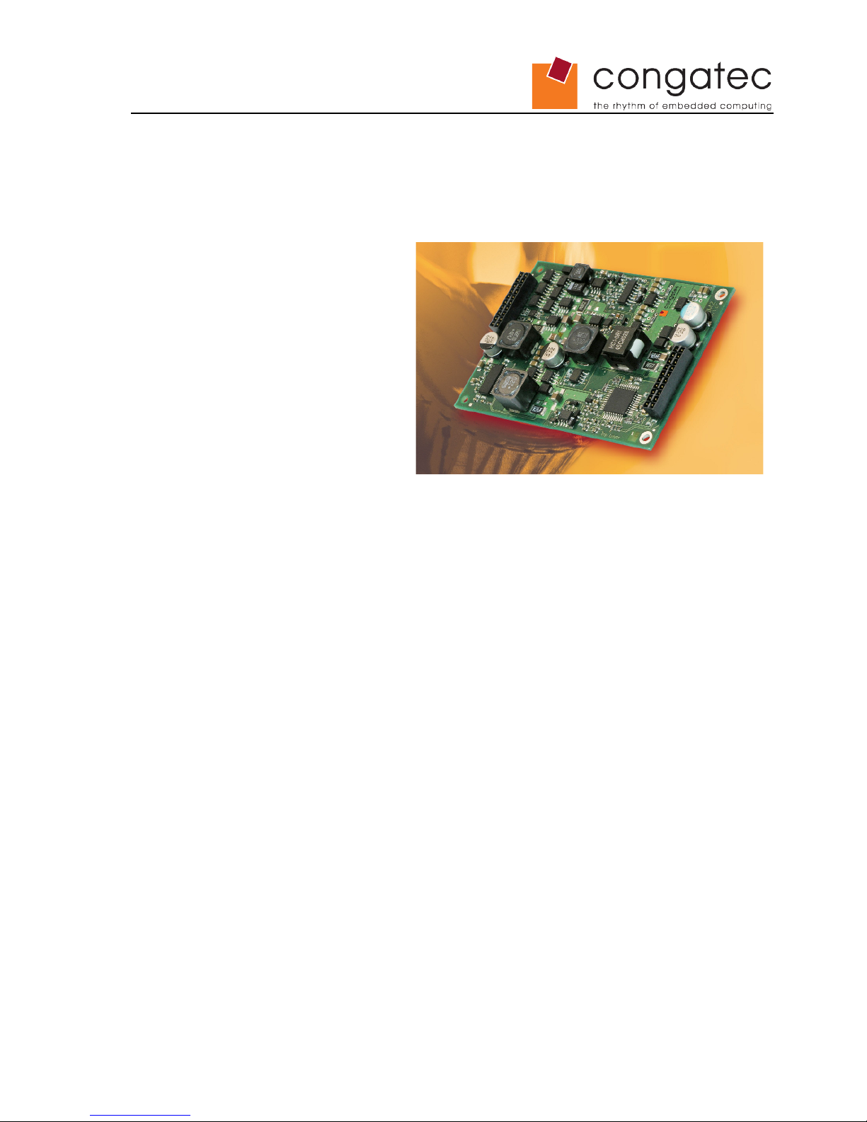
conga-SBM²C
congatec Smart Battery Manager Module
User's Guide
Revision 1.1
Page 2

Revision History
Revision Date (dd.mm.yy) Author Changes
1.0 05.03.08 AHE/GDA Official release
1.1 26.03.08 GDA Changed the 12V signal listed in the optional signal table in section 4.3
to 5V_VCC. 5V system power is the optional signal available, not 12V
system power.
Copyright © 2008 congatec AG SBM2Cm11 2/24
Page 3
Preface
This user's guide provides information about the components, features, and connectors
available on the conga-SBM²C. It is one of three documents that should be referred to
when designing a portable battery/power management solution. The other reference
documents that should be used include the following:
• congatec Battery Management Interface Specification
• Battery System Design Guide
The links to these documents can be found on the congatec AG website at
www.congatec.com
Disclaimer
The information contained within this user's guide, including but not limited to any
product specification, is subject to change without notice.
congatec AG provides no warranty with regard to this user's guide or any other
information contained herein and hereby expressly disclaims any implied warranties of
merchantability or fitness for any particular purpose with regard to any of the foregoing.
congatec AG assumes no liability for any damages incurred directly or indirectly from
any technical or typographical errors or omissions contained herein or for discrepancies
between the product and the user's guide. In no event shall congatec AG be liable for
any incidental, consequential, special, or exemplary damages, whether based on tort,
contract or otherwise, arising out of or in connection with this user's guide or any other
information contained herein or the use thereof.
Intended Audience
This user's guide is intended for technically qualified personnel. It is not intended for
general audiences.
Symbols
The following symbols are used in this user's guide:
Warning
Warnings indicate conditions that, if not observed, can cause personal injury.
Caution
Cautions warn the user about how to prevent damage to hardware or loss of data.
Note
Notes call attention to important information that should be observed.
Copyright © 2008 congatec AG SBM2Cm11 3/24
Page 4

Terminology
Term Description
GB Gigabyte (1,073,741,824 bytes)
GHZ Gigahertz (one billion hertz)
kB Kilobyte (1024 bytes)
MB Megabyte (1,048,576 bytes)
Mbit Megabit (1,048,576 bits)
kHz Kilohertz (one thousand hertz)
MHz Megahertz (one million hertz)
SOH Battery state of health
SOC Battery state of charge
<x>S<y>P Battery pack topology: <x> cells in series, <y> cells in parallel,
e.g. 4S1P: 4 cells in series, no cells parallel
SBSM Smart battery system manager
I/F Interface
N.C. Not connected
N.A. Not applicable
TBD To be determined
Copyright Notice
Copyright © 2008, congatec AG. All rights reserved. All text, pictures and graphics are
protected by copyrights. No copying is permitted without written permission from
congatec AG.
congatec AG has made every attempt to ensure that the information in this document is
accurate yet the information contained within is supplied “as-is”.
Trademarks
Intel and Pentium are registered trademarks of Intel Corporation. Expresscard is a
registered trademark of Personal Computer Memory Card International Association
(PCMCIA). COM Express™ is a registered trademark of PCI Industrial Computer
Manufacturers Group. PCI Express is a registered trademark of Peripheral Component
Interconnect Special Interest Group (PCI-SIG). I²C is a registered trademark of Philips
Corporation. CompactFlash is a registered trademark of CompactFlash Association.
Winbond is a registered trademark of Winbond Electronics Corp. AVR is a registered
trademark of Atmel Corporation. ETX is a registered trademark of Kontron AG.
AMICORE8 is a registered trademark of American Megatrends Inc. Microsoft®,
Windows®, Windows NT®, Windows CE®, Windows XP® and Windows Vista® are
registered trademarks of Microsoft Corporation. VxWorks is a registered trademark of
WindRiver. conga, congatec and XTX are registered trademark of congatec AG. All
product names and logos are property of their owners.
Copyright © 2008 congatec AG SBM2Cm11 4/24
Page 5
Warranty
congatec AG makes no representation, warranty or guaranty, express or implied
regarding the products except its standard form of limited warranty ("Limited Warranty").
congatec AG may in its sole discretion modify its Limited Warranty at any time and from
time to time.
Beginning on the date of shipment to its direct customer and continuing for the
published warranty period, congatec AG represents that the products are new and
warrants that each product failing to function properly under normal use, due to a defect
in materials or workmanship or due to non conformance to the agreed upon
specifications, will be repaired or exchanged, at congatec AG's option and expense.
Customer will obtain a Return Material Authorization ("RMA") number from congatec AG
prior to returning the non conforming product freight prepaid. congatec AG will pay for
transporting the repaired or exchanged product to the customer.
Repaired, replaced or exchanged product will be warranted for the repair warranty
period in effect as of the date the repaired, exchanged or replaced product is shipped by
congatec AG, or the remainder of the original warranty, whichever is longer. This
Limited Warranty extends to congatec AG's direct customer only and is not assignable
or transferable.
Except as set forth in writing in the Limited Warranty, congatec AG makes no
performance representations, warranties, or guarantees, either express or implied, oral
or written, with respect to the products, including without limitation any implied warranty
(a) of merchantability, (b) of fitness for a particular purpose, or (c) arising from course of
performance, course of dealing, or usage of trade.
congatec AG shall in no event be liable to the end user for collateral or consequential
damages of any kind. congatec AG shall not otherwise be liable for loss, damage or
expense directly or indirectly arising from the use of the product or from any other
cause. The sole and exclusive remedy against congatec AG, whether a claim sound in
contract, warranty, tort or any other legal theory, shall be repair or replacement of the
product only
Technical Support
congatec AG technicians and engineers are committed to providing the best possible
technical support for our customers so that our products can be easily used and
implemented. We request that you first visit our website at www.congatec.com for the
latest documentation, utilities and drivers, which have been made available to assist
you. If you still require assistance after visiting our website then please contact our
technical support department by email at [email protected]
Certification
congatec AG is certified to DIN EN ISO 9001:2000 standard.
Copyright © 2008 congatec AG SBM2Cm11 5/24
Page 6
Safety Warning
Warning
When the conga-SBM²C is used in conjunction with the SBM²C Smart Battery
Management Module starter kit, its use is intended for ENGINEERING DEVELOPMENT
OR EVALUATION PURPOSE ONLY and is not considered by congatec AG to be fit for
commercial use. As such, the goods provided in the SBM²C Smart Battery Management
Module starter kit may not be complete in terms of required design-related protective
considerations, including product safety measures typically found in the end product
incorporating the goods. As a prototype, this starter kit does not fall within the scope of
the European Union directive on electromagnetic compatibility and therefore may not
meet the technical requirements of the directive.
Persons handling the product must have electronics training and observe good
laboratory practice standards.
• The SBM²C Smart Battery Management Module starter kit has not been tested
to meet the FCC Rules and/or UL certification and/or CE compliance.
• Do not leave the conga-SBM²C Smart Battery Management Module starter kit
unattended. The battery may reach critical conditions during operation.
• Fire, explosion and severe burn hazard could happen if abused.
• Do not crush, disassemble or short circuit the battery.
If the actual conga-SBM²C module is to be implemented in a carrier board design and
that carrier board design is used in a complete system for series production, then the
system designer/manufacturer must ensure that the system meets all safety,
certification, compatibility and/or any other regulations/requirements set for forth by the
governing bodies of the jurisdiction wherein said system will be made available for
purchase and/or use.
Electrostatic Sensitive Device
All congatec AG products are electrostatic sensitive devices and are packaged
accordingly. Do not open or handle a congatec AG product except at an
electrostatic-free workstation. Additionally, do not ship or store congatec AG products
near strong electrostatic, electromagnetic, magnetic, or radioactive fields unless the
device is contained within its original manufacturer's packaging. Be aware that failure to
comply with these guidelines will void the congatec AG Limited Warranty.
Lead-Free Designs (RoHS)
All congatec AG designs are created from lead-free components and are completely
RoHS compliant.
Copyright © 2008 congatec AG SBM2Cm11 6/24
Page 7

conga-SBM²C Options Information
The conga-SBM²C is currently available in one variant.
Part-No. 026571
Input Voltage
19 V
Output 1
12.0 V/6.0 A
Output 2
5.1 V/6.5 A
Output 3
5.1 V/0.5 A
Copyright © 2008 congatec AG SBM2Cm11 7/24
Page 8

Contents
1 Specifications............................................................................................................................... 9
1.1 Feature List............................................................................................................................... 9
1.2 Supported Operating Systems.................................................................................................. 9
1.3 Mechanical Dimensions........................................................................................................... 10
1.4 Environmental Specifications................................................................................................... 11
1.5 Input Requirements................................................................................................................. 11
1.6 Output Characteristics............................................................................................................. 11
2 Block Diagram............................................................................................................................ 12
3 Cooling....................................................................................................................................... 13
4 Signal Descriptions and Pinout Tables....................................................................................... 14
4.1 Connector J1........................................................................................................................... 15
4.2 Connector J2........................................................................................................................... 16
4.3 Connecting to a COM Express™ CPU Module........................................................................ 17
4.4 Placement and Layout Considerations.................................................................................... 18
5 Power Button, Beeper and I/O.................................................................................................... 19
5.1 Power Button........................................................................................................................... 19
5.2 Beeper Control........................................................................................................................ 19
5.3 I/O Control............................................................................................................................... 19
6 conga-SBM²C Register............................................................................................................... 21
6.1 Software Considerations......................................................................................................... 21
6.2 Interface.................................................................................................................................. 21
6.2.1 OptionalMfgFunction3 Register (0x3D)................................................................................ 23
7 Industry Specifications................................................................................................................ 24
Copyright © 2008 congatec AG SBM2Cm11 8/24
Page 9

1 Specifications
1.1 Feature List
Table 1 Feature Summary
Dimensions
68 mm x 110 mm x 12.5 mm
Input
19 V, max. 4.5 A with load limiter/balancing
Outputs
• Main Power Rail: 12.0 V/6.0 A
• Standby Rail: 5.1 V/0.5 A
• Aux. Rail: 5.1 V/6.5 A
Batteries
• Li-Ion Battery Pack with 2 Stage Protection
must support Smart Battery Specification (SBS) V1.1
• 2S1P to 4S2P (for information about alternative configurations other than 4SxP
contact your local congatec AG representative)
• recommended battery capacity/pack: 2.4 Ah
• recommended battery pack voltage: nom. 14.4 V
Power Modes
• S1: Sleep Mode
• S3: Suspend to RAM
• S5: Soft Off
• G3: Mechanical Off
Supported Modules
• congatec COM Express™ CPU Modules
Additional Features
• support for I²C I/O PCA9555
1.2 Supported Operating Systems
The conga-SBM²C supports the following ACPI Operating Systems.
• Microsoft® Windows® XP/2000
• Microsoft® Windows ®XP Embedded
• Linux
The conga-SBM²C supports the following Operating Systems when using congatec
CGOS interface to communicate to the conga-SBM²C.
• Microsoft® Windows® XP/2000
• Microsoft® Windows ®XP Embedded
• Linux
• QNX
• VxWorks
Copyright © 2008 congatec AG SBM2Cm11 9/24
Page 10
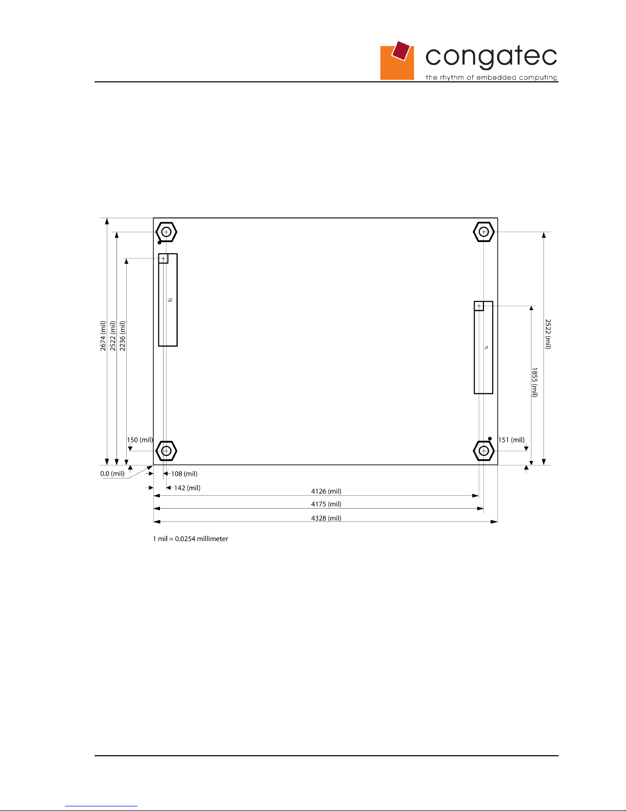
1.3 Mechanical Dimensions
• 109.0 mm x 67.9 mm (4.3” x 2.6”)
• Height approx. 9.7 mm (0.4”) excluding connectors.
Copyright © 2008 congatec AG SBM2Cm11 10/24
Page 11
1.4 Environmental Specifications
Temperature Operation: 0° to 60°C Storage: -20° to +80°C
Humidity Operation: 10% to 90% rel. Storage: 5% to 95% rel.
Note
Humidity specifications are for non-condensing conditions.
The above operating temperatures must be strictly adhered to at all times.
It is the responsibility of the operator to ensure that all components found on the module
operate within the component manufacturer's specified temperature range.
For more information about cooling the conga-SBM²C module see section 3 or contact
congatec technical support.
1.5 Input Requirements
Power Brick Input Battery
Voltage
19.0 V 14.4 V nom.
Tolerance
+/-3% n.a.
Max. Current
4.5 A typ. 6.5 A
Standby Current (G3 Mode)
30 mA typ. < 3 mA typ.
Power (continuous)
85 W typ. n.a.
1.6 Output Characteristics
5V Regulator 5VSB Regulator 12V Regulator CC/CV Charger
Voltage
5.1 V 5.1 V 12.0 V max. 16.80 V
Tolerance
+2.5 %/-5 % +2.5 %/-5 % +/-5 % +/- 1%
Voltage Ripple
@ 10Hz-20MHz
100 mVpp 100 mVpp n.a. n.a.
Max. Current
6.5 A 500 mA 6.0 A 3.0 A
Max. Current (t<10sec.)
7 A 500 mA 2.3 A n.a.
Power (continuous)
30 W 2.5 W 72 W 50 W
Copyright © 2008 congatec AG SBM2Cm11 11/24
Page 12
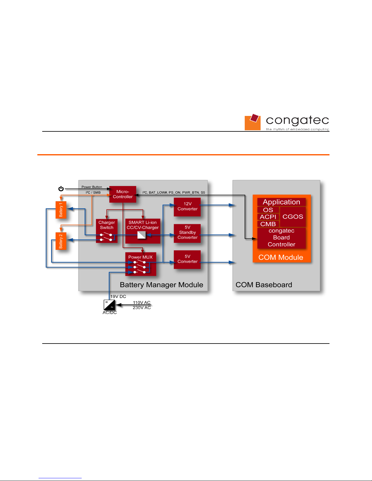
2 Block Diagram
Copyright © 2007 congatec AG SBM2Cm11 12/24
Page 13

3 Cooling
The conga-SBM²C module is designed to meet the latest efficiency standards and
requirements therefore the produced power dissipation is minimal. To be able to use the
module in a wide temperature range, it is recommended that you attach some form of a
cooling solution to the module.
The back of conga-SBM²C does not contain any components and is designed so that
the module can be attached to the system chassis or a heatsink using thermal
conductive gap filler pads.
You can use for example:
• Chomerics THERM-A-GAP:
http://www.chomerics.com
• T-Global L37 series
http://www.tglobal.com.tw/
• Bergquist Gap-Pad
http://www.bergquistcompany.com
Copyright © 2008 congatec AG SBM2Cm11 13/24
Page 14
4 Signal Descriptions and Pinout Tables
The following section describes the signals found on the conga-SBM²C located on the
left and right side of the module.
This table describes the terminology used in this section for the Signal Description
tables. The PU/PD column indicates if an internal pull-up or pull-down resistor has been
used on the conga-SBM²C, if the field entry area in this column for the signal is empty,
then no pull-up or pull-down resistor has been implemented.
The “#” symbol at the end of the signal name indicates that the active or asserted state
occurs when the signal is at a low voltage level. When “#” is not present, the signal is
asserted when at a high voltage level.
Table 2 Signal Tables Terminology Descriptions
Term Description
PU SBM²C internally implemented pull-up resistor
PD SBM²C internally implemented pull-down resistor
I/O 3.3V Bi-directional signal 3.3V tolerant
I/O 5V Bi-directional signal 5V tolerant
I 3.3V Input 3.3V tolerant
I 5V Input 5V tolerant
I/O 3.3VSB Input 3.3V tolerant active in standby state
O 3.3V Output 3.3V signal level
O 5V Output 5V signal level
P Power Input/Output
PP Push-Pull Output
OC Open Collector
Copyright © 2008 congatec AG SBM2Cm11 14/24
Page 15
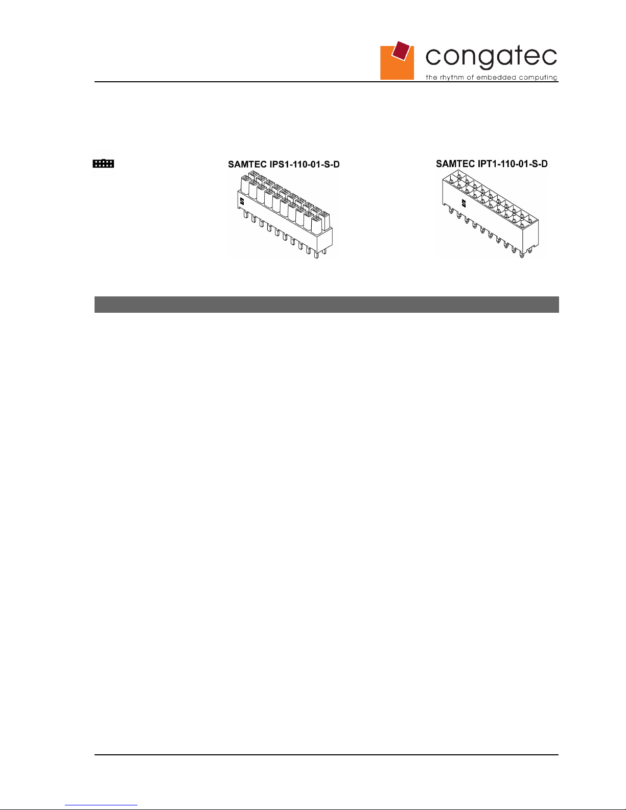
4.1 Connector J1
Connector Type
mates with
Table 2 J1 signals
Pin Signal Description I/O PU/PD
1 5V_VCC 5V system power output P
2 5V_VCC 5V system power output P
3 GND Ground P
4 GND Ground P
5 GND -> +12V 12V system power output P
6 GND -> +12V 12V system power output P
7 GND Ground P
8 GND Ground P
9 5VSB System standby power P
10 C_SCL I²C-bus clock line used for communication with the system host I/O 5V
11 C_SDA I²C-bus clock line used for communication with the system host I/O 5V
12 C_SLP_S5# Signal for S5 state I 5V
13 Reset#
14 BPR Buzzer output O 5V PP
15 I_OnBut# Power button signal from front panel I/O 5V PU 15k µC_VCC
16 C_BATLOW# Interrupt output O 5V OC, 8 mA
17 C_PBTN# Power button signal to the CPU module O 5V OC, 8 mA
18 C_PSON# Power on/off request line from the CPU module I 5V
19 M_SCL Clock line of internal I²C-bus I/O 5V PU 15k µC_VCC
20 M_SDA Data line of internal I²C-bus I/O 5V PU 15k µC_VCC
Copyright © 2008 congatec AG SBM2Cm11 15/24
Page 16
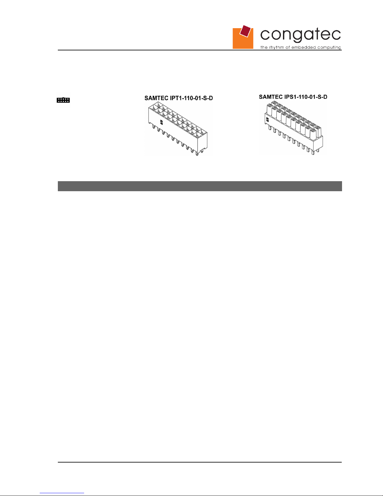
4.2 Connector J2
Connector Type
mates with
Table 2 J2 signals
Pin Signal Description I/O PU/PD
1 BAT1 Battery 1 power P
2 BAT1 Battery 1 power P
3 GND Ground P
4 GND Ground P
5 BAT2 Battery 2 power P
6 BAT2 Battery 2 power P
7 TDI JTAG interface I/O 5V PU 10k µC_VCC
8 TDO JTAG interface I/O 5V PU 10k µC_VCC
9 TCK JTAG interface I/O 5V PU 10k µC_VCC
10 TMS JTAG interface I/O 5V PU 10k µC_VCC
11 B2_SCL I²C-bus data line used for communi cation with battery 1 I/O 5V PU 15k µC_VCC
12 B2_SDA I²C-bus data line used for communication with battery 1 I/O 5V PU 15k µC_VCC
13 B2_TP Reserved
14 B1_TP Reserved
15 B1_SDA I²C-bus clock line used for communication with battery 2 I/O 5V PU 15k µC_VCC
16 B1_SCL I²C-bus clock line used for communication with battery 2 I/O 5V PU 15k µC_VCC
17 GND Ground P
18 GND Ground P
19 Uin Power input 19V/4.5A P
20 Uin Power input 19V/4.5A P
Copyright © 2008 congatec AG SBM2Cm11 16/24
Page 17
4.3 Connecting to a COM Express™ CPU Module
The conga-SBM²C signals listed in the following table must be connected to a COM
Express™ CPU module via the carrier board.
conga-SBM²C
Signal
COM Express™
Signal
+12V VCC_12V
5VSB VCC_5V_SBY
GND GND
C_SCL I2C_CK
C_SDA I2C_DAT
C_BATLOW# BATLOW#
C_PBTN# PWRBTN#
C_PSON# SUS_S3#
C_SLP_S5# SUS_S5#
The following table lists additional conga-SBM²C signals that are mandatory and must
be implemented on the COM Express™ carrier board in order to ensure basic
functionality.
SBM²C Signal Description
I_OnBut# Must be connected to a signal used to turn on the system such as a button on a front panel
BAT1 Battery 1 power connection
B1_SDA, B1_SCL I²C-bus used for communication with battery 1
Uin Connection to 19V/4.5A power source
The following table lists additional conga-SBM²C signals that are optional and can be
implemented on the COM Express™ carrier board. Utilizing these signals will provide
additional functionality.
SBM²C Signal Description
BPR Buzzer output
µC_VCC Supply for external I/O
TDI, TDO, TCK, TMS JTAG interface
M_SDA, M_SCL SBM²C internal I²C-bus
BAT2 Battery 2 power connection
B2_SDA, B2_SCL I²C-bus used for communication with battery 2
5V_VCC 5V system power
Copyright © 2008 congatec AG SBM2Cm11 17/24
Page 18

The following table lists signals which are important when designing a battery powered
system that is in compliance with the congatec Battery Management Interface
Specification.
Signal
(COM Express™)
Description
BATLOW# This signal is used by the battery system to generate interrupts upon special events such as AC
power changes, attaching/detaching of batteries, battery low conditions, etc. A low pulse of at
least one microsecond is necessary to be recognized by the system host.
PS_ON# A low level on PS_ON# or high level on SUS_S3# indicates that the Battery Management
System should turn on system power. Otherwise the Battery Management System must turn off
system power.
PWRBTN# This signal is used to send a power-on request to the CPU module. The low pulse should be
about 250 milliseconds long.
I2CLK I²C-bus clock line used for communi cation between Battery Management System controller and
system host
I2DAT I²C-bus data line used for communication between Battery Management System controller and
system host
SLP_S5# This signal is active low when the system switches to the S5 (soft off) state.
4.4 Placement and Layout Considerations
The conga-SBM²C is designed to minimize component count and layout complexity of
the carrier baseboard but there is still the necessity to follow high power and noise
separation layout rules.
• Utilize enough trace width for power rails such as 5V, battery rails, DC-in rails.
• Keep the trace length of the power rails short.
• Keep power rails away from noise sensitive COM Express™ signals (LVDS, IDE,
VGA, Ethernet, USB).
• Keep power rails away from noisy COM Express™ signals (PCICLK, etc.).
• Keep battery bus and COM Express™ I²C Bus away from noisy signals.
• Route all I²C Buses and SMBuses CLK and DATA signals close together.
• Add ESD protective devices to signals where necessary
For more detailed information about high power layout rules consult literature found on
the web.
Copyright © 2008 congatec AG SBM2Cm11 18/24
Page 19
5 Power Button, Beeper and I/O
5.1 Power Button
The conga-SBM²C is intended to be used to control the power of the complete system.
The signal is pulled-up internally so there is no need for an external pull-up resistor on
the carrier baseboard. Pull the signal low by a pushbutton to control the conga-SBM²C
module. There is no need for special debounce components because the controller
onboard the conga-SBM²C will debounce the pushbutton signal via software.
The pushbutton behavior is generally comparable to the button in a standard ATX
system.
Button Down Time Functionality
120 ms < t < 4 s Turn on
Turn off, shutdown Windows
t > 4 s Instant off
5.2 Beeper Control
The conga-SBM²C provides an active high beeper output signal. The maximum load on
this pin should not exceed 10mA. The output voltage level on this pin is 3.3V/5V and
follows uC_VCC.
Beeper Functionality
3 beeps Warning level, configurable
continuous beep Alarm level, configurable
5.3 I/O Control
The conga-SBM²C supports the Philips/NXP PCA9555 I²C I/O controller
(http://www.nxp.com). You can attach LEDs to indicate different modes and statuses.
The conga-SBM²C addresses the PCA9555 using the addresses shown below.
I²C address HEX MSB LSB
7 bit 0x20 0 1 0 0 0 0 0
8 bit 0x40 0 1 0 0 0 0 0 R#/W
Make sure you configured the PCA9555 address jumpers to the specific address.
Copyright © 2008 congatec AG SBM2Cm11 19/24
Page 20
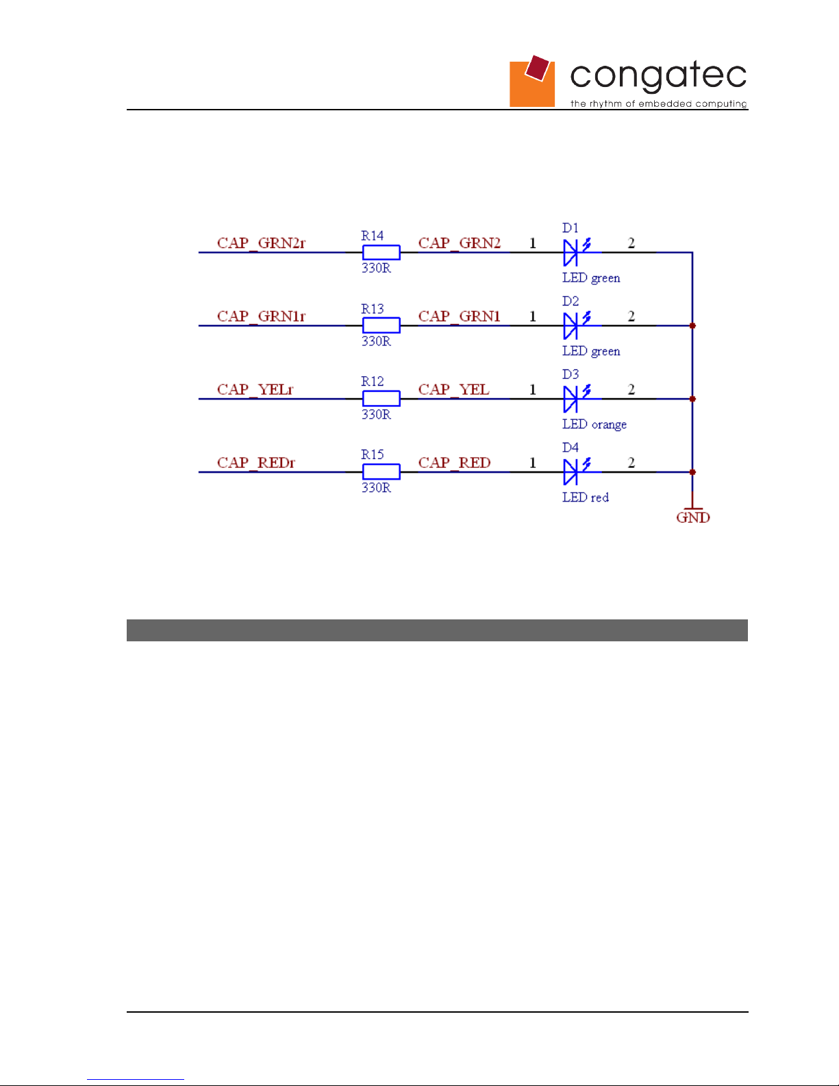
The status LED outputs are configured to be push outputs, therefore the LEDs should
be connected with common GND. Depending on the power supply voltage of the
PCA9555, the selected series resistance to the LEDs must meet the LEDs' and
PCA9555's maximum current requirements.
The following table shows the behavior of the different status LEDs that display
operating and battery status.
LED Functionality Port
LINE 18.0 V < Uin < 20 V
Flashing during charging
P0.5
PWRON All output voltages are on
Flashing in S3 mode
P0.4
GREEN2 SOC: 75% to 100% P0.0
GREEN1 SOC: 50% to 74% P0.1
YELLOW SOC: 25% to 49% P0.2
RED SOC: 0% to 24%
Flashing when SOC below configurable level
P0.3
BAT1 EMPTY Flashing when SOC below configurable level P0.6
BAT2 EMPTY Flashing when SOC below configurable level P0.7
Copyright © 2008 congatec AG SBM2Cm11 20/24
Page 21
6 conga-SBM²C Register
6.1 Software Considerations
The conga-SBM²C fully complies with the congatec Battery Management Interface
Specification. As a result of this, the conga-SBM²C is recognized automatically by all
congatec CPU modules supporting battery management. Running an ACPI operating
system will bring notebook functionality to the system without the need for additional
software installation.
CPU modules from other vendors may require a BIOS firmware update to be compatible
with the congatec Battery Management System.
6.2 Interface
The I²C device addresses of the conga-SBM²C module are:
I²C address HEX MSB LSB
7 bit 0x0B 0 0 0 1 0 1 1
8 bit 0x16 0 0 0 1 0 1 1 R#/W
The following table lists all defined registers. The column 'Access' shows how the
system host (cBC) accesses the individual registers. An entry 'r' or 'r/w' means that the
implementation of the particular register is mandatory in order for the congatec battery
management solution to function properly. An empty entry means that the particular
register is optional and may be implemented by the SBSM for completeness.
Function
Register
Address
Access Data Type
Data
Length
ManufacturerAccess 0x00 r Battery manufacturer specific word
RemainingCapacityAlarm 0x01 r/w mAh / unsigned integer word
RemainingTimeAlarm 0x02 r/w Minutes / unsigned integer word
BatteryMode 0x03 r Flags / bit map word
AtRate 0x04 r mA / signed integer word
AtRateTimeToFull 0x05 r Minutes / unsigned integer word
AtRateTimeToEmpty 0x06 r Minutes / unsigned integer word
AtRateOK 0x07 r TRUE or FALSE / boolean word
Temperature 0x08 r 0.1°K / unsigned integer word
Voltage 0x09 r mV / unsigned integer word
Current 0x0A r mA / signed integer word
AverageCurrent 0x0B r mA / signed integer word
MaxError 0x0C r Percent / unsigned integer word
RelativeStateOfCharge 0x0D r Percent / unsigned integer word
AbsoluteStateOfCharge 0x0E r Percent / unsigned integer word
RemainingCapacity 0x0F r mAh / unsigned integer word
Copyright © 2008 congatec AG SBM2Cm11 21/24
Page 22

Function
Register
Address
Access Data Type
Data
Length
FullChargeCapacity 0x10 r mAh / unsigned integer word
RunTimeToEmpty 0x11 r Minutes / unsigned integer word
AverageTimeToEmpty 0x12 r Minutes / unsigned integer word
AverageTimeToFull 0x13 r Minutes / unsigned integer word
ChargingCurrent 0x14 r mA / unsigned integer word
ChargingVoltage 0x15 r mV / unsigned integer word
BatteryStatus 0x16 r Flags / bit map word
CycleCount 0x17 r Count / unsigned integer word
DesignCapacity 0x18 r mAh or 10mWh / unsigned integer word
DesignVoltage 0x19 r mV / unsigned integer word
SpecificationInfo 0x1A r Packed data / bit map word
ManufactureDate 0x1B r Packed date / unsigned integer word
SerialNumber 0x1C r Number / unsigned integer word
Reserved 0x1D - 0x1F
ManufacturerName 0x20 r Character string block
DeviceName 0x21 r Character string block
DeviceChemistry 0x22 r Character string block
ManufacturerData 0x23 r Battery manufacturer specific block
Reserved 0x25 - 0x2E
OptionalMfgFunction5 0x2F r Battery manufacturer specific block
Reserved 0x30 - 0x3B
Firmware Revision 0x3C r/w Unsigned integer, congatec specific word
Blink Warn Capacity 0x3D r/w Unsigned integer, congatec specific / see section 6.2.1 word
Beep Warn Capacity 0x3E r/w Unsigned integer, congatec specific word
Beep On Capacity 0x3F r/w Unsigned integer, congatec specific word
Reserved 0x40
BatterySystemState 0x41 r/w Packed data / bit map word
BatterySystemStateCont 0x42 r Packed data / bit map word
Reserved 0x43
BatterySystemInfo 0x44 r Packed data / bit map word
Reserved 0x45 - 0xFF
Copyright © 2008 congatec AG SBM2Cm11 22/24
Page 23
6.2.1 OptionalMfgFunction3 Register (0x3D)
Today's computer systems are able to distinguish between different power off states.
For a battery powered system the states S3 (suspend to RAM), S5 (soft off) and G3
(mechanical off) are of particular importance. The main system power is switched off in
all cases, however the system standby power is switched off in the G3 state only.
Of course the system states S3 and S5 provide features such as wake-on-LAN or fast
system resume times. However, for a battery powered system with long standby times it
may be more useful to switch off to the G3 state to minimize power consumption.
Therefore, congatec has defined two bits 'S3' and 'S5' in the smart battery register
OptionalMfgFunction3. These bits are used to signal the SBSM (Smart Battery System
Manager) whether it may additionally switch off the system standby power after the main
system power has been switched off. The following table shows the detailed
OptionalMfgFunction3 register definition:
Bit
Number
Bit
Name
Default
Value
Description
0-7 0xA Blink warn level [percent]
8 S5 0 Setting this bit to 1 tells the SBSM that it must not switch off the system
standby power because the system is required to stay in the S5 state after
switching off the main system power.
Note: When the SBSM is completely restarted it must reset this bit to its
default value. Usually this bit is set/reset by the system host during the
power-on-self-test (POST) of the system based on CMOS RAM settings.
9 S3 0 Setting this bit to 1 tells the SBSM that it must not switch off the system
standby power because the system is going to enter the S3 state when
switching off the main system power. This bit is set by the system host right
before the system enters the S3 state. The S3 bit must be cleared by the
SBSM when the system resumes from the S3 state, i.e. when main system
power is turned on again.
10 S1 0 This bit indicates that the system is running in a power saving mode. It is
set/reset by the system host when entering/leaving the power saving mode.
11-15 Reserved
Copyright © 2008 congatec AG SBM2Cm11 23/24
Page 24
7 Industry Specifications
The list below provides links to industry specifications that apply to congatec AG
modules.
Specification Link
COM Express™ Specification http://www.picmg.org
congatec White Paper 'Embedded Battery Management' http://www.congatec.com/fileadmin/Technology/battery_m
anagement/fb_battery_management_-_en.pdf
congatec Battery Management Interface Specification http://www.congatec.com/sbm2.html
Smart Battery System Specifications http://www.sbs-forum.org/specs/
Copyright © 2008 congatec AG SBM2Cm11 24/24
 Loading...