

Page 1
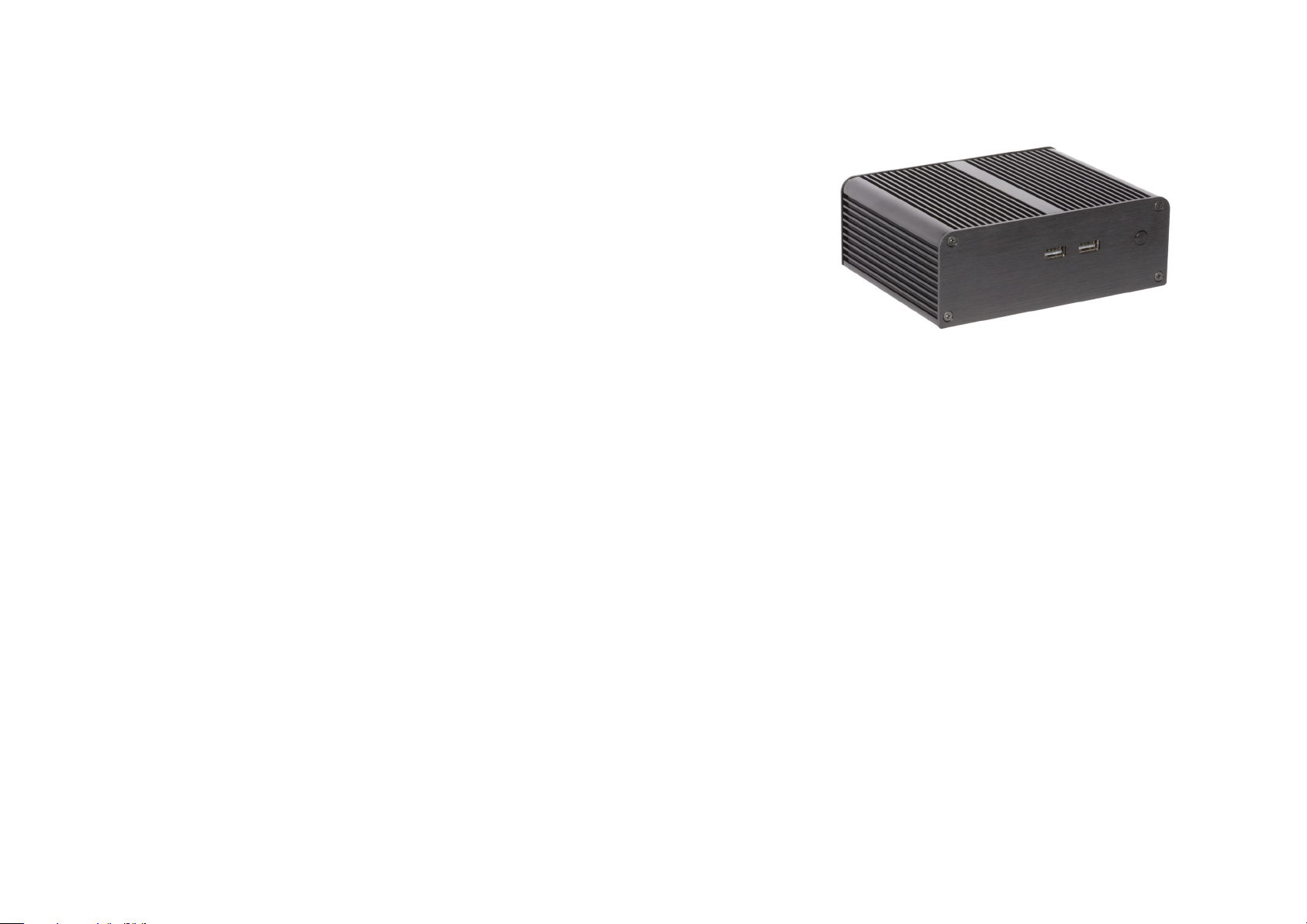
conga-PITX
Chassis for congatec Pico-ITX Modules
Quick Start Guide
Revision 1.0
Page 2
1 Introduction
1.1 Supported Boards
The conga-PITX supports a range of congatec modules as shown in the table below:
Part No - Chassis Part No - Supported Boards
052556 - conga-PA5/Chassis PIX-APH1 lidded,
commercial temperature
052557 - conga-PA5/Chassis PIX-APH1 non-lidded,
commercial temperature
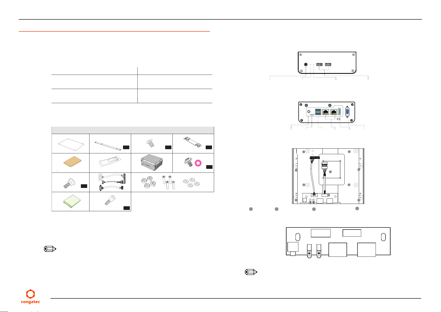
1.2 What is in the Package
① ② ③ ④
⑤ ⑥ ⑦ ⑧
⑨ ⑩ ⑪
x2
⑫ ⑬
① HDD protective film
④ VESA mount bracket
⑦ Chassis Panels with PCB
⑩ Cables (LED, USB, COM)
⑤ Copper block (for PN:052557 )
⑪ Case feet items
048100 - conga-PA5/E3950-8G
048101 - conga-PA5/E3940-4G
048102 - conga-PA5/E3930-4G
048120 - conga-PA5/N4200-8G
048121 - conga-PA5/N3350-4G
048123 - conga-PA5/N4200-4G
Contents
x2 x8 x2
x2
③ 2.5" HDD/SSD screws② 2.5" HDD/SDD mounting bracket
⑥ Thermal compound
⑨ VESA mounting screw⑧ Motherboard screws and washers
⑫ Gap pad ⑬ COM port screw
1.3 Front Panel Layout
Power switch
1.4 Back Panel Layout
1.5 Internal Layout
x4
A
CPU stackB Front panel PCB
1.6 Internal PCB
Power LED
USB CPower
D
D D
USB 3.0 LAN
C
USB
A
C C
B
C
Mainboard standoffs
LED cable
DP++
C
USB cable
USB 2.0 portHard drive LED
COM Port
D
D
Mounting hole for HDD/SSD bracket
Note
1. The received product may differ slightly from the illustrations in this guide. While the drawings
may differ, the basic steps described in this guide remains the same.
2. For optimal storage installation, use right-angled SATA cables. To order from congatec AG,
use the following part numbers: 48000030 (SATA data) and 14000205 (SATA power)
3. Apply thermal compound only on variants with non-lidded CPU (PN: 052557)
Note
The motherboard may damage if you connect the panel to the wrong headers. Check the
specific module's manual for connection tips.
Copyright © 2019 congatec AG conga-PITXq10 2/3
2-pin Power
switch
PWR & HDD
LED
USB 2.0
connector
USB 2.0
connector
Page 3
2 Installation
④
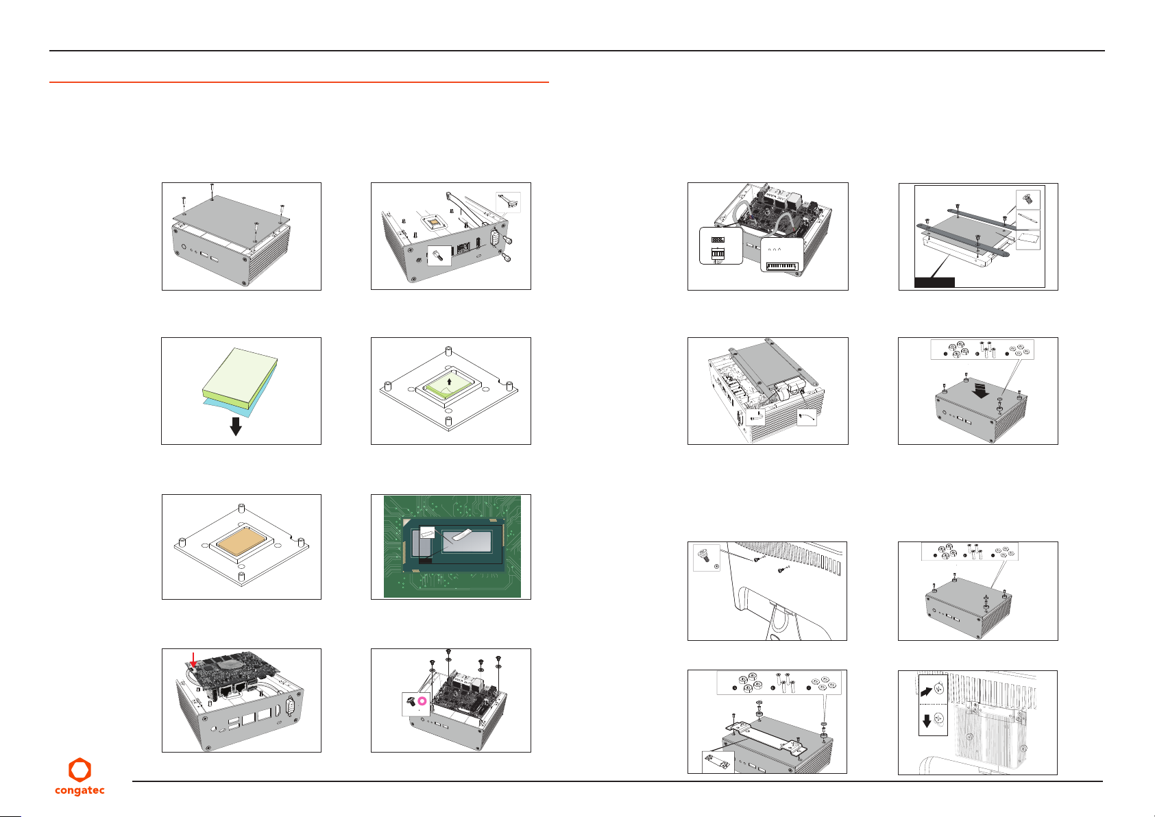
2.1 Assembly
1. Remove the back cover: 2. Mount the COM cable to the chassis
(if required)
⑩
⑬
3. Remove the blue film from the gap
pad:
5. Place the copper block on the gap
pad (only for PN: 052557):
4. Place the gap pad on the heat sink
and remove the transparent film
6. Apply the CPU thermal compound
(only for PN: 052557):
⑥
CPU
9. Connect LED and USB cables from
front panel to congatec board:
USB2.0 connector
Brown
Blue
Yellow
KEY
Orange
Red
GND
Black
White
Purple
11. Connect SATA cables to HDD and
mount assembly to chasis:
PN: 48000030
2.2 VESA Mounting
1. Attach VESA mounting screw: 2. Detach case feet items:
⑨
10. Secure the HDD protection and the
brackets to the hard drive:
③
②
Power
Power LED
H.D.D LED
- White
+ Red
- White
+ Green
- White
+ Orange
Empty
Empty
Empty
Empty
Empty
Empty
2.5” HDD / SSD
①
12. Attach the back cover and the case
feet items:
⑪
PN: 14000205
⑪
7. Connect the COM cable to the
board (if required):
8. Mount the congatec board. Screw
positions are shown below:
3. Mount the VESA bracket: 4. Align the chassis:
⑪
⑧
Copyright © 2019 congatec AG conga-PITXq10 3/3
 Loading...