

Page 1

conga-IGX Mini ITX SBC
Mini-ITX Professional Series single board computer based on AMD Embedded G-Series SoC
User’s Guide
Revision 0.2 (Preliminary)
Page 2
Copyright © 2014 congatec AG IGX1m02 2/134
Revision History
Revision Date (yyyy.mm.dd) Author Changes
0.1 2014.05.13 AEM • Preliminary release
0.2 2014.05.28 AEM
• Updated section 12.1 “System Watchdog (WD)” and section 15.1.1 “If you want to open the Boot Menu Immediately”
• Deleted section 17.1 “Erase Disk” and section 22.6.1 “Diagnostic Program” because the conga-IGX does not support these features.
Page 3
Copyright © 2014 congatec AG IGX1m02 3/134
Preface
This user’s guide provides information about the components, features and connectors available on the conga-IGX Mini-ITX SBC (Single Board
Computer).
Disclaimer
The information contained within this user’s guide, including but not limited to any product specication, is subject to change without notice.
congatec AG provides no warranty with regard to this user’s guide or any other information contained herein and hereby expressly disclaims
any implied warranties of merchantability or tness for any particular purpose with regard to any of the foregoing. congatec AG assumes
no liability for any damages incurred directly or indirectly from any technical or typographical errors or omissions contained herein or for
discrepancies between the product and the user’s guide. In no event shall congatec AG be liable for any incidental, consequential, special, or
exemplary damages, whether based on tort, contract or otherwise, arising out of or in connection with this user’s guide or any other information
contained herein or the use thereof.
Intended Audience
This user’s guide is intended for technically qualied personnel. It is not intended for general audiences.
Lead-Free Designs (RoHS)
All congatec AG designs are created from lead-free components and are completely RoHS compliant.
Electrostatic Sensitive Device
All congatec AG products are electrostatic sensitive devices and are packaged accordingly. Do not open or handle a congatec AG product
except at an electrostatic-free workstation. Additionally, do not ship or store congatec AG products near strong electrostatic, electromagnetic,
magnetic, or radioactive elds unless the device is contained within its original manufacturer’s packaging. Be aware that failure to comply with
these guidelines will void the congatec AG Limited Warranty.
Page 4
Copyright © 2014 congatec AG IGX1m02 4/134
Symbols
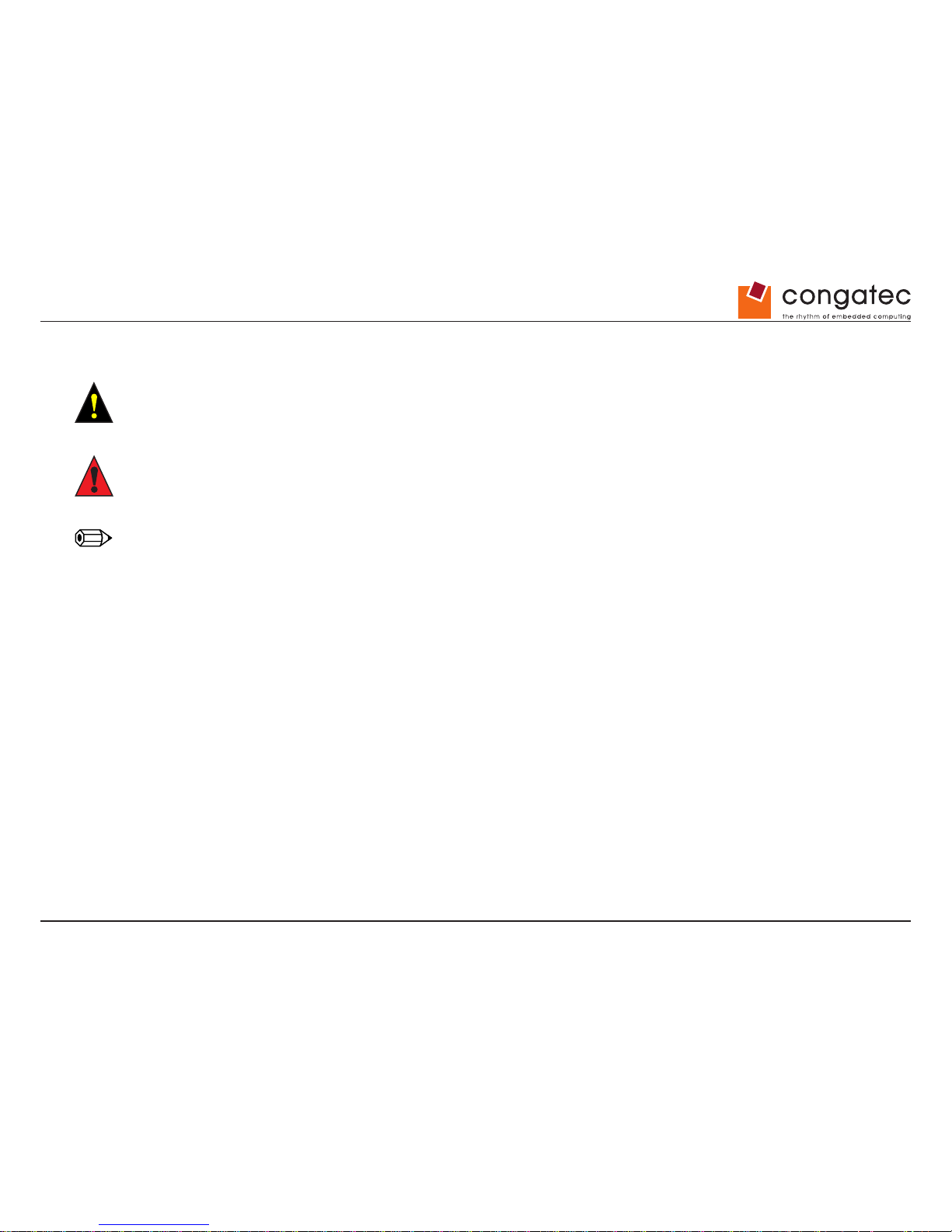
The following symbols are used in this user’s guide:
Warning
Warnings indicate conditions that, if not observed, can cause personal injury.
Caution
Cautions warn the user about how to prevent damage to hardware or loss of data.
Note
Notes call attention to important information that should be observed.
Copyright Notice
Copyright © 2014, congatec AG. All rights reserved. All text, pictures and graphics are protected by copyrights. No copying is permitted without
written permission from congatec AG.
congatec AG has made every attempt to ensure that the information in this document is accurate yet the information contained within is
supplied “as-is”.
Trademarks
Product names, logos, brands, and other trademarks featured or referred to within this user’s guide, or the congatec website, are the property
of their respective trademark holders. These trademark holders are not afliated with congatec AG, our products, or our website.
Page 5
Copyright © 2014 congatec AG IGX1m02 5/134
Warranty
congatec AG makes no representation, warranty or guaranty, express or implied regarding the products except its standard form of limited
warranty (“Limited Warranty”) per the terms and conditions of the congatec entity, which the product is delivered from. These terms and
conditions can be downloaded from www.congatec.com. congatec AG may in its sole discretion modify its Limited Warranty at any time and
from time to time.
The products may include software. Use of the software is subject to the terms and conditions set out in the respective owner’s license
agreements, which are available at www.congatec.com and/or upon request.
Beginning on the date of shipment to its direct customer and continuing for the published warranty period, congatec AG represents that the
products are new and warrants that each product failing to function properly under normal use, due to a defect in materials or workmanship or
due to non conformance to the agreed upon specications, will be repaired or exchanged, at congatec’s option and expense.
Customer will obtain a Return Material Authorization (“RMA”) number from congatec AG prior to returning the non conforming product freight
prepaid. congatec AG will pay for transporting the repaired or exchanged product to the customer.
Repaired, replaced or exchanged product will be warranted for the repair warranty period in effect as of the date the repaired, exchanged
or replaced product is shipped by congatec, or the remainder of the original warranty, whichever is longer. This Limited Warranty extends to
congatec’s direct customer only and is not assignable or transferable.
Except as set forth in writing in the Limited Warranty, congatec makes no performance representations, warranties, or guarantees, either
express or implied, oral or written, with respect to the products, including without limitation any implied warranty (a) of merchantability, (b) of
tness for a particular purpose, or (c) arising from course of performance, course of dealing, or usage of trade.
congatec AG shall in no event be liable to the end user for collateral or consequential damages of any kind. congatec shall not otherwise be
liable for loss, damage or expense directly or indirectly arising from the use of the product or from any other cause. The sole and exclusive
remedy against congatec, whether a claim sound in contract, warranty, tort or any other legal theory, shall be repair or replacement of the
product only.
Certication
congatec AG is certied to DIN EN ISO 9001 standard.
C
E
R
T
I
F
I
C
A
T
I
O
N
I
S
O
9
0
0
1
TM
Page 6
Copyright © 2014 congatec AG IGX1m02 6/134
Technical Support
congatec AG technicians and engineers are committed to providing the best possible technical support for our customers so that our products
can be easily used and implemented. We request that you rst visit our website at www.congatec.com for the latest documentation, utilities and
drivers, which have been made available to assist you. If you still require assistance after visiting our website then contact your local congatec
sales representative.
Terminology
Term Description
SBC Single Board Computer
SoC System on Chip
PCI Express (PCIe) Peripheral Component Interface Express – next-generation high speed Serialized I/O bus
PCI Express Lane One PCI Express Lane is a set of 4 signals that contains one differential line for
transmitter and one differential line for receiver. Clocking information is embedded into the
data stream.
x1, x2, x4, x16 x1 refers to one PCI Express Lane of basic bandwidth; x2 to a collection of two PCI Express
Lanes; etc. Also referred to as x1, x2, x4 or x16 link.
VGA Video Graphics Array
USB Universal Serial Bus
SATA Serial AT Attachment: serial-interface standard for hard disks
AC ‘97/HDA Audio CODEC (Coder-Decoder) / High Denition Audio
LPC Low Pin-Count Interface: a low speed interface used for peripheral circuits such as Super
I/O controllers, which typically combine legacy-device support into a single IC.
I²C Bus Inter-Integrated Circuit Bus: is a simple two-wire bus with a software-dened protocol that
was developed to provide the communications link between integrated circuits in a system.
SM Bus System Management Bus: is a popular derivative of the I²C-bus.
SPI Bus Serial Peripheral Bus
GBE Gigabit Ethernet
LVDS Low-Voltage Differential Signaling
TPM Trusted Platform Module
HDMI High Denition Multimedia Interface
DVI Digital Visual Interface
S/PDIF Sony/Philips Digital Interface Format
DDC Display Data Channel is an I²C bus interface between a display and a graphics adapter.
N.C. Not connected
N.A. Not available
T.B.D. To be determined
Page 7
Copyright © 2014 congatec AG IGX1m02 7/134
Contents
1 Safety Instructions ...................................................................12
2 System Memory Conguration .................................................13
3 Feature Overview conga-IGX ..................................................14
3.1 conga-IGX Reference Silkscreen .............................................14
3.2 Block Diagram ..........................................................................15
3.3 USB Structure ..........................................................................16
3.4 conga-IGX Variants ..................................................................17
3.5 External Connectors conga-IGX ..............................................18
3.6 Onboard Components ..............................................................19
3.7 Heatsink Installation Notes ......................................................20
3.8 Heatsink Installation Notes ......................................................21
4 Heatsink/Heatpipe Installation Notes .......................................22
5 Display Options ........................................................................23
5.1 Basic Display Features ............................................................23
5.2 LVDS Display & Backlight Inverter Connection ........................24
5.3 LVDS Connector details ..........................................................25
5.4 Backlight Inverter Connector Details .......................................27
5.5 LVDS Timing & Screen Resolution .........................................28
5.6 LVDS Tool ................................................................................32
5.7 LVDS Cabling Reference .........................................................33
5.8 Dual-DVI Output .......................................................................34
5.9 VGA Output ..............................................................................35
5.10 DVI or VGA plus LVDS .............................................................36
5.11 Internal & External graphics use in parallel ..............................37
6 Power Supply Features ............................................................38
6.1 12V / 19-24V DC Connector ....................................................38
6.2 Requirements for 12V / 19-24V operation ...............................39
6.3 Power option for internal devices .............................................40
6.3.1 Requirements for DC operation ...............................................40
6.3.2 Limited conga-IGX output current ............................................40
6.4 Drive Power Connector ............................................................41
6.5 Drive Power Connector ............................................................42
7 Internal Connectors ..................................................................43
7.1 Feature Connector ..................................................................43
7.2 Internal USB 2.0 Ports .............................................................44
7.3 Internal USB 3.0 Ports .............................................................45
7.4 Internal Audio Ports – Front panel Audio ................................46
7.5 Internal Audio Ports - SPDIF ....................................................47
7.6 m-SATA / SATA ........................................................................47
7.7 Mini-PCIe Connector ................................................................48
7.8 Internal Serial Connector (COM3) ...........................................48
7.9 Internal Parallel Port Connector ..............................................49
7.10 PCI Express Extension Slot .....................................................49
7.11 Intrusion Connector ..................................................................50
7.12 Fan Connector .........................................................................51
7.13 Front Panel Connector .............................................................52
7.14 Additional Jumper Settings ......................................................52
8 System Monitoring ...................................................................53
8.1 conga-IGX: Fans ......................................................................53
8.2 conga-IGX Sensors .................................................................54
8.3 SilentFanCongManager .........................................................55
8.4 Temperature Reference Points conga-IGX ..............................56
9 Power Consumption .................................................................58
9.1 Sample Conguration ..............................................................58
10 Operating System Support .......................................................59
10.1 MS Windows / MS Windows Embedded Compact ..................59
10.2 Linux Support ..........................................................................59
11 conga-IGX T ools ......................................................................60
11.1 Common conga-IGX Tools ......................................................60
12 Miscellaneous ..........................................................................61
Page 8
Copyright © 2014 congatec AG IGX1m02 8/134
12.1 System Watchdog (WD)...........................................................61
12.2 Trusted Platform Module (TPM) ...............................................62
12.3 RealTime Clock (RTC) Accuracy .............................................62
12.4 BIOS/CMOS Reset (“BIOS Setup Defaults”) ...........................62
13 Known Issues and Important Notes .........................................63
13.1 Support for MS Windows XP ...................................................63
13.2 Graphics Memory .....................................................................63
13.3 AMD “Eyenity” Support ..........................................................63
13.4 HDMI Audio Support ................................................................63
13.5 Audio: Recording Level via HDA Front Panel .........................63
13.6 Video Playback (WMV, MP4) ...................................................64
14 Introduction ..............................................................................65
14.1 Notational conventions ............................................................65
15 Navigating BIOS Setup ...........................................................67
15.1 Open BIOS Setup ..................................................................67
15.1.1 If you want to open the Boot Menu immediately ....................67
15.1.2 If you wish to boot immediately from LAN .............................68
15.2 Navigating BIOS Setup ...........................................................68
15.3 Exiting BIOS Setup .................................................................68
16 Main Menu – System functions ...............................................69
16.1 System Information .................................................................69
16.1.1 Board and Firmware Details ...................................................69
16.1.2 Network C ontroller Details ......................................................70
16.1.3 Processor Details ....................................................................70
16.1.4 Memory MemoDetails .............................................................70
16.2 System Language ...................................................................71
16.3 System Date/System Time ......................................................71
16.4 Access Level ...........................................................................71
17 Advanced Menu – Advanced system conguration ................72
17.1 TPM (Trusted Platform Module) Computing ............................73
17.1.1 TPM Support ...........................................................................73
17.1.2 TPM State ...............................................................................73
17.1.3 Pending TPM operation ..........................................................73
17.1.4 Current TPM Status Information .............................................74
17.2 SATA Conguration .................................................................74
17.2.1 SATA Mode ............................................................................74
17.2.2 mSATA Support ........................................................................74
17.3 Graphics Conguration ...........................................................75
17.3.1 Primary Display .......................................................................75
17.3.2 Internal Graphics .....................................................................75
17.3.3 IGD Memory ............................................................................75
17.4 LVDS Conguration .................................................................75
17.4.1 LVDS Support .......................................................................... 76
17.4.2 LVDS Panel Cong Select ......................................................76
17.4.3 Non-EDID Support .................................................................. 76
17.4.4 LVDS Mode .............................................................................76
17.4.5 LVDS Channel Swap ..............................................................77
17.4.6 LVDS Backlight-Enable Polarity ..............................................77
17.4.7 LVDS Brightness Control ........................................................77
17.4.8 LVDS Brightness .....................................................................78
17.4.9 POST Screen Mode .............................................................. 78
17.5 USB Conguration ...................................................................78
17.5.1 USB Devices ...........................................................................78
17.5.2 Legacy USB Support ..............................................................78
17.5.3 USB Transfer Time-Out ...........................................................79
17.5.4 Mass Storage Devices ............................................................79
17.6 USB Port Security ...................................................................79
17.6.1 USB Port Control ....................................................................80
17.6.2 USB Device Control ................................................................80
17.7 System Monitoring ...................................................................80
17.7.1 Controller Revision .................................................................. 80
17.7.2 Firmware Version .....................................................................80
17.7.3 Chassis Type ...........................................................................81
17.7.4 TCV Version ........................................................................... 81
17.7.5 Fan Control .............................................................................81
17.7.6 Fan2 Wiring .............................................................................82
Page 9
Copyright © 2014 congatec AG IGX1m02 9/134
17.8 Onboard Device Conguration................................................82
17.8.1 Audio Conguration .................................................................82
17.8.2 High Precision Event Timer Conguration .............................. 82
17.8.3 LAN 1 ......................................................................................83
17.8.4 LAN 2 ......................................................................................83
17.9 Super IO Conguration ...........................................................83
17.9.1 Super IO Chip ........................................................................83
17.10 Serial Port 0 Conguration .....................................................83
17.10.1 Serial Port ...............................................................................83
17.10.2 Device Settings .......................................................................84
17.10.3 Change Settings ......................................................................84
17.11 Serial Port 1 Conguration .....................................................84
17.11.1 Serial Port ...............................................................................85
17.11.2 Device Settings .......................................................................85
17.11.3 Change Settings ......................................................................85
17.12 Parallel Port Conguration ......................................................85
17.12.1 Parallel Port .............................................................................86
17.12.2 Device Settings .......................................................................86
17.12.3 Change Settings ......................................................................86
17.12.4 Device Mode ...........................................................................86
17.13 Network Stack .........................................................................87
17.13.1 Ipv4 PXE Support ...................................................................87
17.13.2 Ipv6 PXE Support ...................................................................87
18 Security Menu – Security Functions ........................................88
18.1 Password Description .............................................................88
18.2 Administrator Password ........................................................... 89
18.3 User Password ........................................................................89
18.4 User Password on Boot .........................................................90
18.5 Cabinet Monitoring ..................................................................90
18.6 Skip Password on WOL .........................................................90
18.7 FLASH Write ...........................................................................90
18.8 Secure Boot ............................................................................91
18.8.1 Platform Mode .........................................................................91
18.8.2 Secure Boot ............................................................................91
18.8.3 Secure Boot Control ...............................................................91
18.8.4 Secure Boot Mode ..................................................................92
18.8.5 Key Management ....................................................................92
18.9 HDD Security Conguration ....................................................95
18.9.1 HDD Password on Boot .........................................................95
18.10 HDD n / HDD-ID .....................................................................95
18.10.1 HDD Password Description ....................................................95
18.10.2 HDD Password Conguration .................................................95
18.10.3 Security Supported ..................................................................95
18.10.4 Security Enabled .....................................................................95
18.10.5 Security Locked .......................................................................96
18.10.6 Security Frozen .......................................................................96
18.10.7 HDD User Password Status ...................................................96
18.10.8 HDD Master Password Status ................................................96
18.10.9 Set User Password .................................................................96
18.10.10 Set Master Password .............................................................96
19 Power Menu – Energy saving functions...................................97
19.1 Power Settings ........................................................................97
19.1.1 Power LED in S3 ...................................................................97
19.1.2 Power On Source ...................................................................98
19.1.3 Low Power Soft Off ................................................................98
19.1.4 Power Failure Recovery ........................................................... 98
19.1.5 Hibernate like Soft Off ............................................................99
19.1.6 USB At Power Off ................................................................. 99
19.2 Wake-Up Resources ................................................................99
19.2.1 LAN ..........................................................................................99
19.2.2 Wake On LAN Boot ..............................................................100
19.2.3 Wake Up Timer .....................................................................100
19.2.4 Hour .......................................................................................100
19.2.5 Minute ....................................................................................100
19.2.6 Second ...................................................................................100
19.2.7 Wake Up Mode .....................................................................100
19.2.8 Wake Up Day .......................................................................101
19.2.9 USB Keyboard ......................................................................101
Page 10
Copyright © 2014 congatec AG IGX1m02 10/134
20 Event Logs – Conguration and
Display of the Event Log .102
20.1 Change SMBIOS event log settings .....................................102
20.1.1 SMBIOS Event Log .............................................................. 102
20.1.2 Erase Event Log ...................................................................103
20.1.3 When Log is full ...................................................................103
20.1.4 Log System Boot Event ....................................................... 103
20.1.5 MECI ......................................................................................103
20.1.6 METW ....................................................................................103
20.1.7 Log OEM Codes ...................................................................104
20.1.8 Convert OEM codes .............................................................104
20.1.9 View SMBIOS Event Log .....................................................104
21 Boot Menu – System boot ....................................................105
21.1 Boot Conguration .................................................................106
21.1.1 Bootup NumLock State .........................................................106
21.1.2 Quiet Boot .............................................................................106
21.1.3 Fast On .................................................................................107
21.1.4 USB Support .........................................................................107
21.1.5 PS2 Devices Support ...........................................................108
21.1.6 POST Errors ........................................................................108
21.1.7 Remove Invalid Boot Options .............................................. 108
21.1.8 Boot Removable Media ........................................................ 108
21.1.9 Virus Warning ........................................................................109
21.1.10 Prefer USB Boot ...................................................................109
21.1.11 Boot option priorities .............................................................109
21.1.12 CSM Conguration ................................................................110
22 Save & Exit Menu – Finish BIOS Setup ................................ 112
22.1 Save Changes and Exit .......................................................112
22.2 Discard Changes and Exit – quit without saving ...................112
22.3 Save Changes and Reset .................................................... 113
22.4 Discard Changes and Reset ................................................113
22.5 Save Options ........................................................................113
22.5.1 Save Changes ....................................................................... 113
22.5.2 Discard Changes ................................................................... 113
22.5.3 Restore Defaults.................................................................... 113
22.5.4 Save as User Defaults ......................................................... 113
22.5.5 Restore User Defaults .......................................................... 113
22.6 Boot Override .......................................................................114
23 BIOS Update ......................................................................... 115
24 Appendix: LVDS Reference Cable Pinouts ............................116
24.1 AUO_G0121SN01 LVDS Cable Pinout ..................................117
24.1.1 Panel Pinout AUO G0121SN01 ............................................. 117
24.1.2 Inverter Cable Plan ................................................................ 118
24.1.3 Inverter Pinout Green C&C GH093A ..................................... 118
24.2 AUO_G150XG01 LVDS Cable Pinout ...................................11 9
24.2.1 Panel Pinout AUO G150XG01 ............................................... 119
24.2.2 Inverter Cable Plan ................................................................ 120
24.2.3 Inverter Pinout Green C&C GH001A .....................................120
24.3 AUO-M170EG01-VD LVDS Cable Pinout ..............................121
24.3.1 Panel Pinout AUO M170EG01-VD .........................................121
24.3.2 Inverter Cable Plan ................................................................ 122
24.3.3 Inverter Pinout Green C&C GH053A .....................................122
24.4 AUO-M190EG01 V0 LVDS Cable Pinout ...............................123
24.4.1 Panel Pinout AUO-M190EG01 V0 .........................................123
24.4.2 Inverter Cable Plan ................................................................ 124
24.4.3 Inverter Pinout Green C&C GH053A .....................................124
24.5 Sharp LQ190 LVDS Cable Pinout ..........................................125
24.5.1 Panel Pinout Sharp LQ190 .................................................... 125
24.5.2 Inverter Cable Plan ................................................................ 126
24.6 Inverter Pinout PowerSystems PS-DA0412-05 .....................126
24.6.1 Sharp LQ150 LVDS Cable Pinout ..........................................127
24.6.2 Panel Pinout Sharp LQ150 .................................................... 127
24.6.3 Inverter Cable Plan ................................................................ 128
24.6.4 Inverter Pinout TDK CXA-0349 ..............................................128
24.7 Philips LB121S03-TL01 LVDS Cable Pinout .........................129
24.7.1 Panel Pinout Philips LB121S03-TL01 .................................... 129
Page 11
Copyright © 2014 congatec AG IGX1m02 11/134
24.7.2 Inverter Cable Plan ................................................................ 130
24.7.3 Inverter Pinout Green C&C GH001HB ................................... 130
24.8 NEC NL6448BC33-63D LVDS Cable Pinout .........................131
24.8.1 Panel Pinout NEC NL6448BC33-63D .................................... 131
24.8.2 Inverter Cable Plan ................................................................ 132
24.8.3 Inverter Pinout NEC 104PW201 ............................................ 132
24.9 Philips LM150X08 LVDS Cable Pinout ..................................133
24.9.1 Panel Pinout Philips LM150X08 ............................................. 133
24.9.2 Inverter Cable Plan ................................................................ 134
24.9.3 Inverter Pinout Green C&C GH001A .....................................134
Page 12
Copyright © 2014 congatec AG IGX1m02 12/134
1 Safety Instructions
Do not connect or disconnect any cables or modules to or from any onboard connectors (except for the rear I/O connectors) until the conga-IGX
is completely powered down.
Any damage caused to the conga-IGX by misuse of the onboard connectors is excluded from the standard warranty. congatec cannot be held
liable for any damage that results from incorrect use of any onboard connectors.
The system integrator is fully responsible for the usage of the appropriate connectors and cables in order to fulll the technical requirements
(electrical contact, durability, power/current levels, signal integrity etc.)
Heatsink Backplate
Caution
Insulating foil of backplate must NOT be removed, otherwise conga-IGX may be damaged due to a possible short circuit.
Page 13
Copyright © 2014 congatec AG IGX1m02 13/134
2 System Memory Conguration
If you use only one memory module, then you must insert this memory module into slot A (upper slot), otherwise the conga-IGX will not operate.
Note
The conga-IGX will not operate if memory slot A is empty.
Page 14
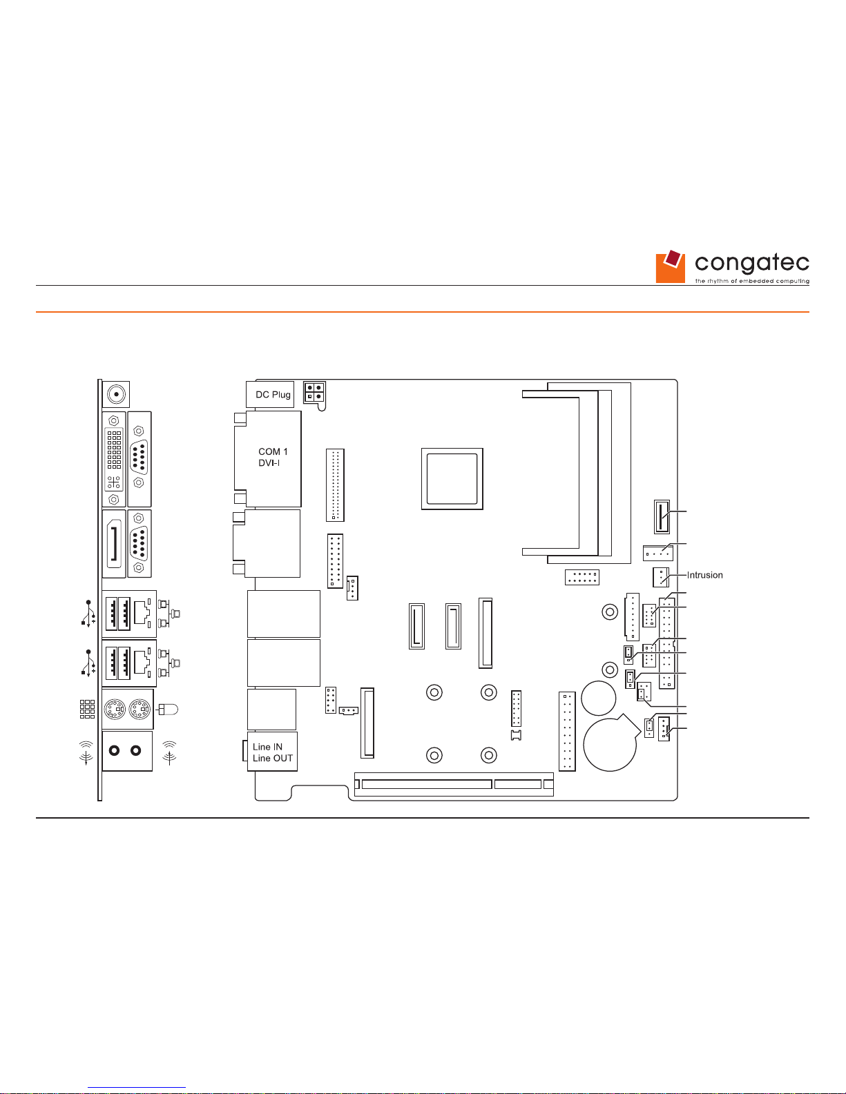
Copyright © 2014 congatec AG IGX1m02 14/134
3 Feature Overview conga-IGX
3.1 conga-IGX Reference Silkscreen
Drive Power
COM 3
LPT
Front Panel
Mouse
Keyboard
Power
COM 2
DisplayPort
PCIe X4
FAN 2
FAN 1
SPDIF
Front Audio
mini PCIe
mSATASATA0 SATA1
LAN
2x USB 2.0
LAN
2x USB 2.0
LVDS
Backlight
TPM GPIO
Buzzer
Battery
2x USB 3.0
2x USB 2.0
LVDS
CPU
Memory Module 1
Memory Module 2
BIOS Recovery Settings
LVDS Supply Settings
USB 2.0
LVDS BL Control Settings
System Power On Settings
DC DVI-I DisplayPort
COM1 COM2
Page 15
Copyright © 2014 congatec AG IGX1m02 15/134
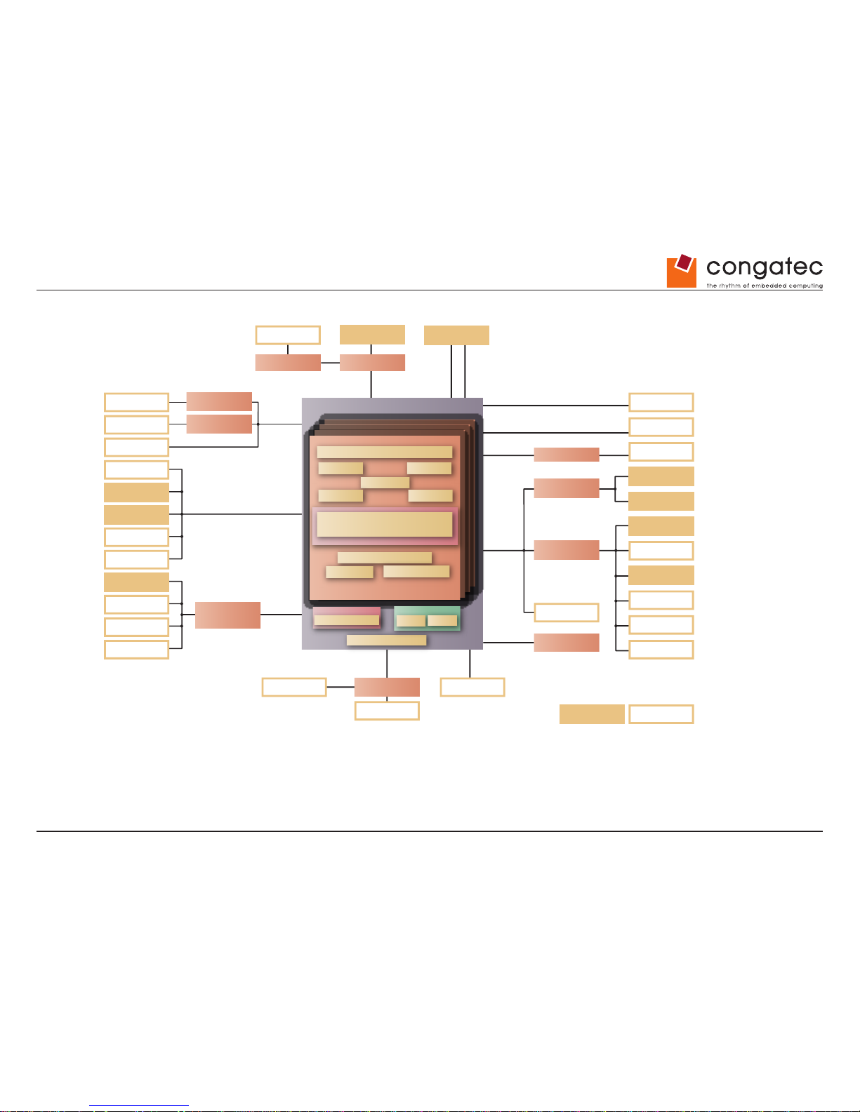
3.2 Block Diagram
AMD Embedded G-Series SOC
TPM Module
2x SO-DIMM DDR3
APU Plaorm
Quad Core single-chip
2
nd
Generaon AMD Embedded G-Series
Next generaon graphics
AMD Radeon™ HD 8000
Core #1 Core #2
low power
Core #3 Core #4
high performance
2 MB Shared L2
ASRC
Integrated I/O - HUB
High Definion Audio
ROM
RAM
Int. Memory
DDR3-1600
HDA
Audio
ALC671
PCIe x4
PCIe x4 Gen2
SM
PCA
8 Bit GPIO
Super I/O #1
Super I/O #2
LPC
COM 1
PS/2
COM 2
COM 3 (int.)
Parallel
FAN1
External I/O Internal I/O
FAN2
INTRUSION
BIOS
SPI
SATA0
SATA-3
SATA-3
SATA-Switch
SATA1
mSATA
DVI-I
VGA
TDP1
DP
LTDP0
LTDP0
MUX
DP2LVDS
LVDS
4x PCIe x1
Gen2
PCIe Minicard
RTLK
RTLK
LAN1 1Gb
LAN2 1Gb
Audio IN/OUT
Buzzer
USB2.0/USB3.0
USB3.0 2 Ports
USB2.0 2 Ports
USB2.0 2 Ports
USB2.0 2 Ports
USB2.0 2 Ports
Frontpanel
SPDIF Out
Page 16
Copyright © 2014 congatec AG IGX1m02 16/134
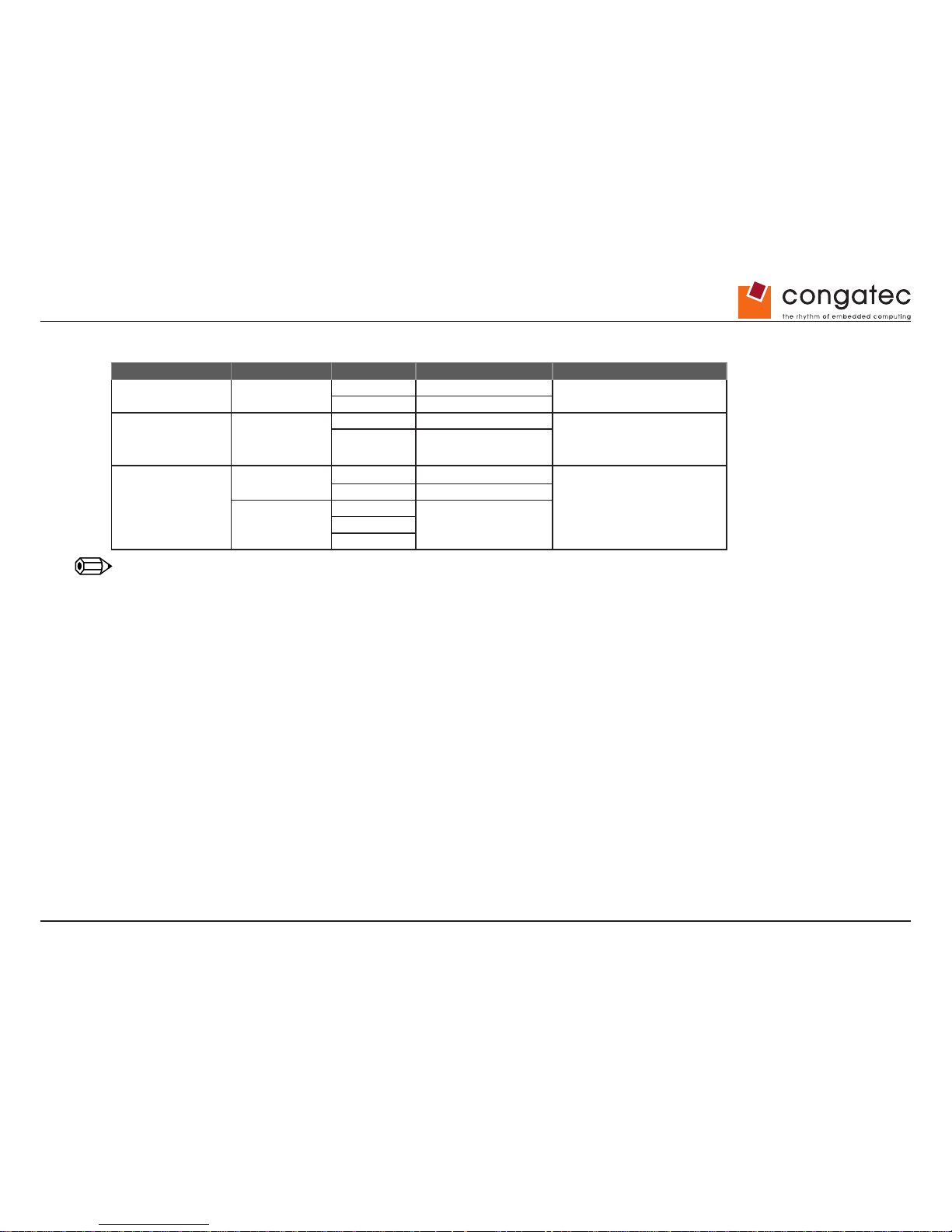
3.3 USB Structure
USB Port # Location USB Version USB Controller USB Fuse
0-3
Rear USB ports
(IO-Shield)
1.1 OHCI 1
common fuse 5V/2A
(see note below)
2.0 EHCI 1
4-7
Pin Header (4,7)
Internal “Stick” Port
(5)
Mini-PCIe (6)
1.1 OHCI 2
common fuse 5V/2A
(see note below)
2.0 EHCI 2
8-9
USB3 Header
(xHCI disabled)
1.1 OHCI 3
common fuse 5V/2A
(see note below)
2.0 EHCI 3
USB3 Header
(xHCI enabled)
1.1
xHCI2.0
3.0
Note
Specied maximum USB supply current: 0.5A/5V for each USB2.0 port; 0.9A/5V for each USB3.0 port.
Internal USB Cable Length:
USB 2.0: Board will only support USB specication compliant cables with a maximum length of 12 inches (30.5cm) for USB 2.0. The cables
must have an impedance of 90 ohms. Furthermore, the cables must have a twisted signaling pair for each individual port. That means each
port has two twisted signaling pairs and one GND cable and one power cable in one jacket with inner and outer shield. The shield of the cable
must be connected with the GND of the connector. These cables can be connected to the internal dual channel connector. For further details
see section 6 in the USB 2.0 specication.
USB 3.0: conga-IGX will only support USB 3.0 compliant cables with a maximum length of 16 inches (40.5cm) (internal USB cable to the USB
connector type A). The differential characteristic impedance for the SDP pairs is recommended to be within 90 Ω +/- 7 Ω. USB 3.0 cables have
eight primary conductors: three twisted signal pairs for USB data paths and a power pair. In addition to the twisted signal pair for USB 2.0
data path, two twisted signal pairs are used to provide the SuperSpeed data path, one for the transmit path and one for the receive path. USB
3.0 receptacles (both upstream and downstream) are backward compatible with USB 2.0 connector plugs. USB 3.0 cables and plugs are not
intended to be compatible with USB 2.0 upstream receptacles.
Page 17
Copyright © 2014 congatec AG IGX1m02 17/134
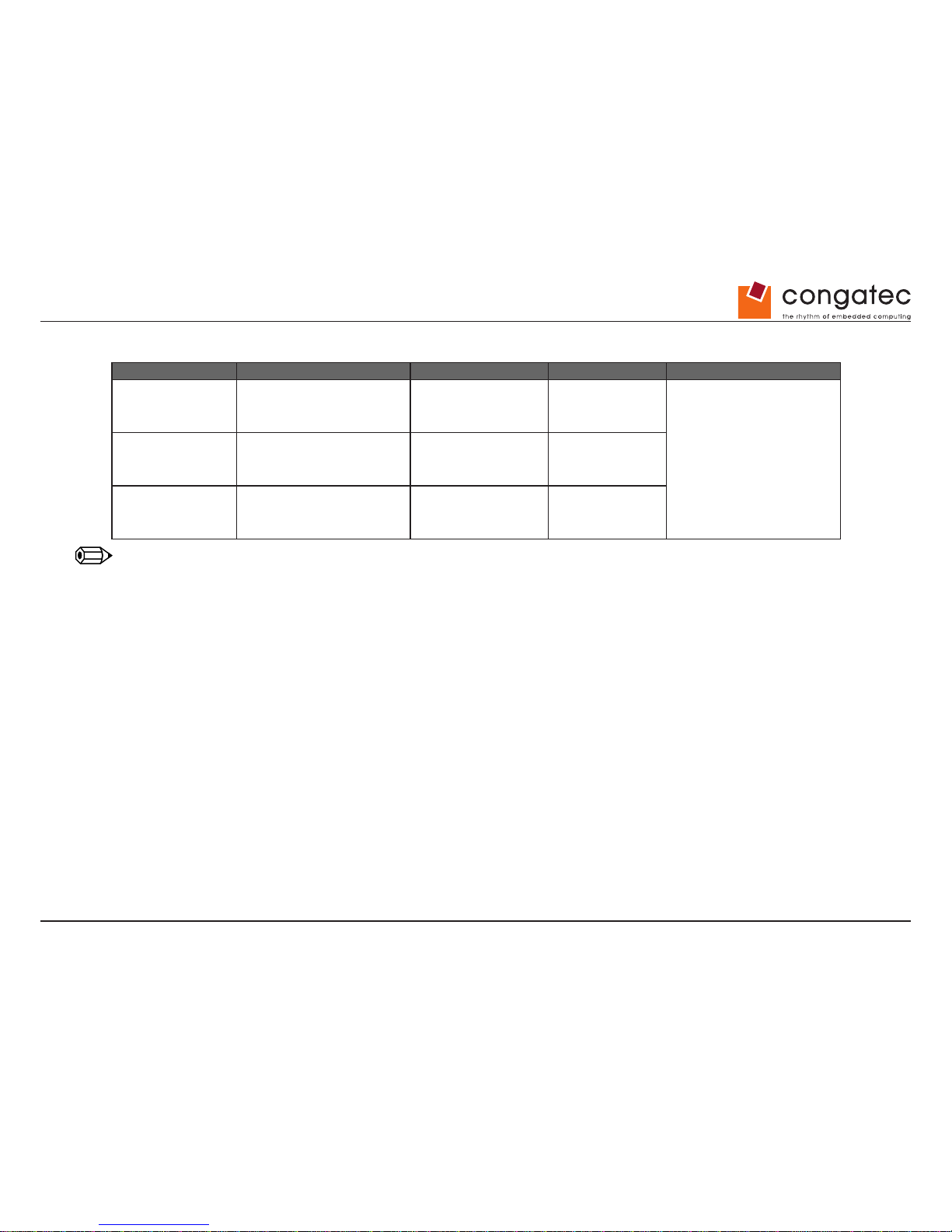
3.4 conga-IGX Variants
Processor (SoC) Graphics Memory Display Options
conga-IGX/210HA
GX-210HA
Dual Core 1.0 GHz / 9W
64kB L1 Cache per Core
1MB L2 Cache shared
Radeon HD 8210E
300 MHz
DDR3 / 1333
(see note below)
1 x DVI-I;
1 x DP V1.2;
1 x LVDS 24Bit Dual Ch.;
max. 2 independent displays
(DVI-I & DP or DVI & LVDS)
conga-IGX/217GA
GX-217GA
Dual Core 1.65 GHz / 15W
64kB L1 Cache per Core
1MB L2 Cache shared
Radeon HD 8280E
450 MHz
DDR3 / 1600
(see note below)
conga-IGX/420CA
GX-420CA
Quad Core 2.00 GHz / 25W
64kB L1 Cache per Core
2MB L2 Cache shared
Radeon HD 8400E
600 MHz
DDR3 / 1600
(see note below)
Note
1. Maximum supported memory clock.
2. For all conga-IGX variants, DDR3-1333 (CL9) or DDR3-1600 (CL11) memory modules can be installed.
3. Up to 16GB SDRAM (unbuffered, no ECC) is possible.
4. Two memory sockets available (single channel mode). Compliant with JEDEC DDR3 1.5V, DDR3L 1.35V and DDR3U 1.25V
Page 18
Copyright © 2014 congatec AG IGX1m02 18/134
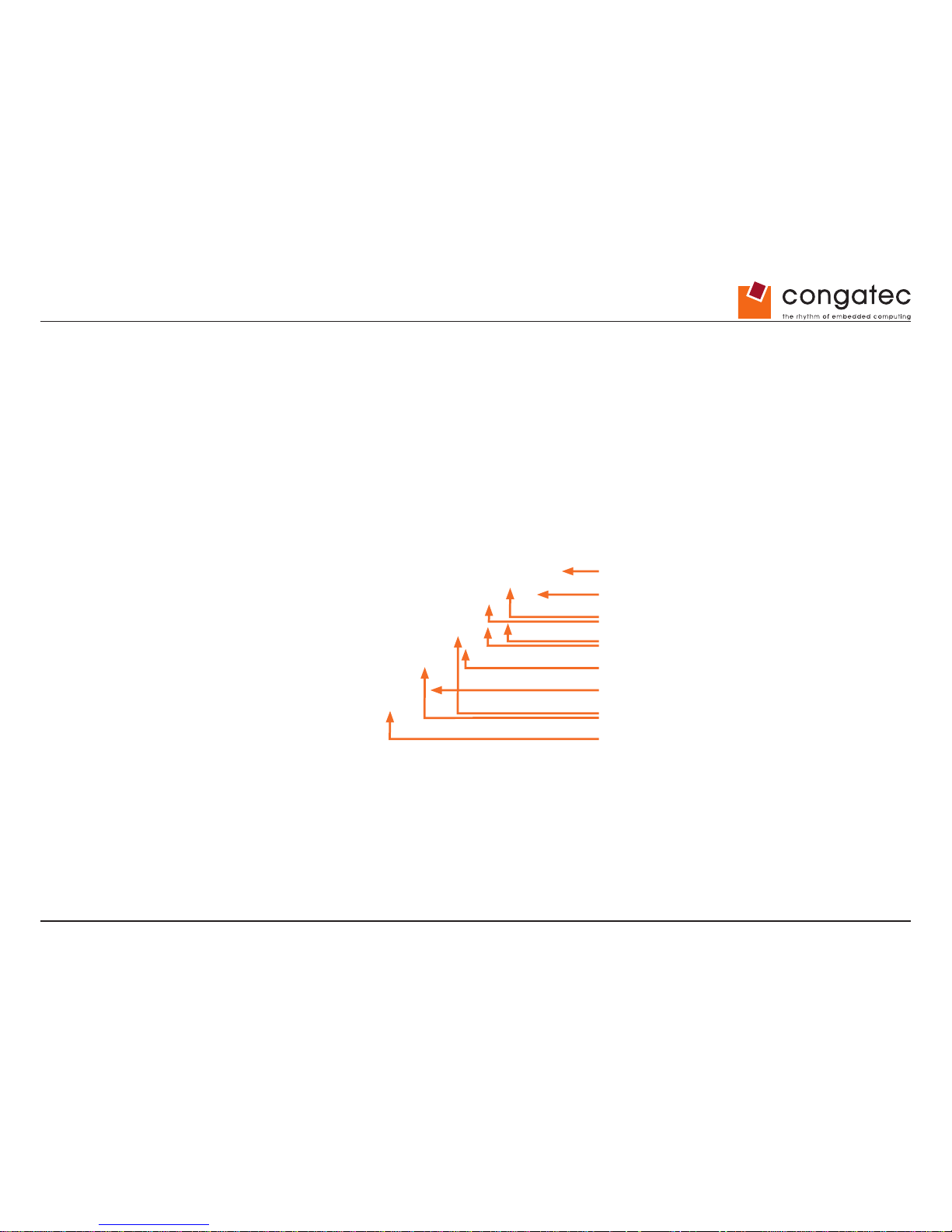
3.5 External Connectors conga-IGX
Audio
PS/2 Mouse & Keyboard
Dual Lan
4x USB
DisplayPort
DVI-I
2x RS232
DC Input (12V / 19-24V)
Page 19
Copyright © 2014 congatec AG IGX1m02 19/134
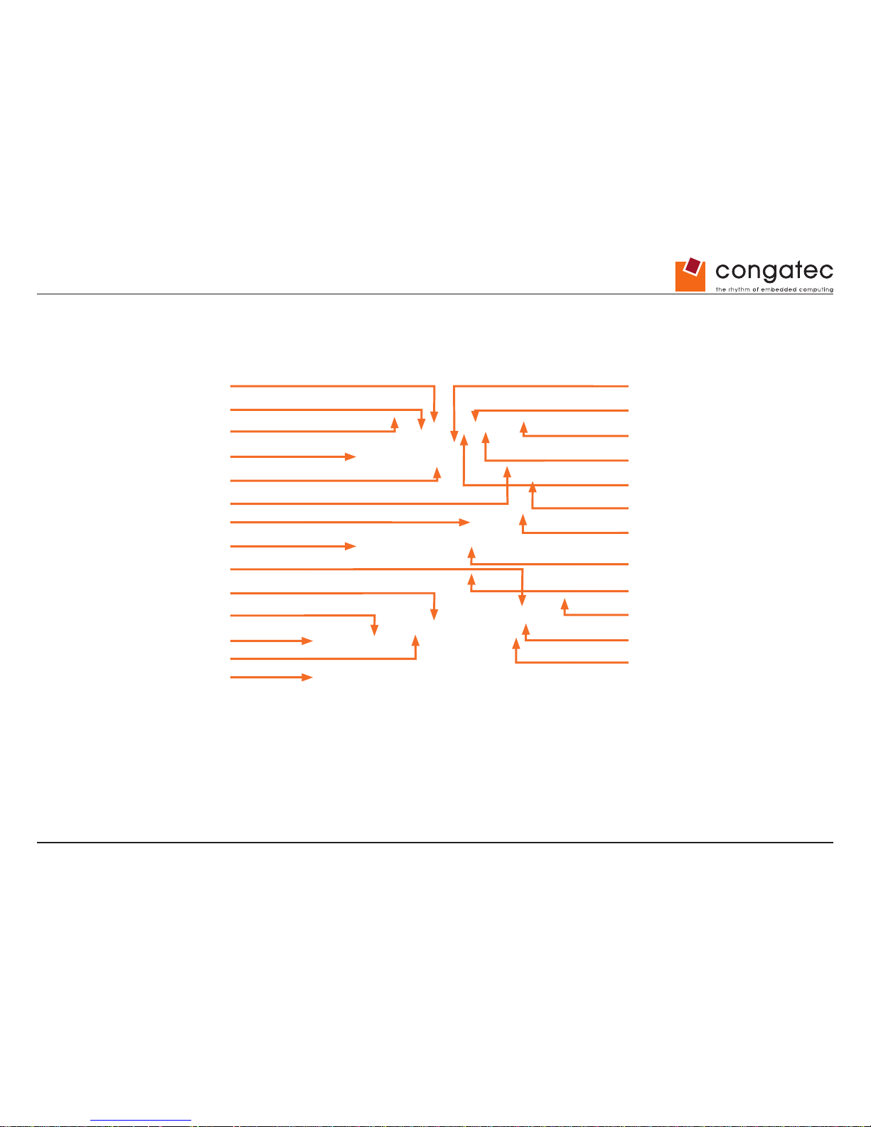
3.6 Onboard Components
Intrusion Backlight Control
Drive Power
LPT
USB 2.0
Chassis Fan
2x SO-DIMM
Front panel
2x USB 2.0
COM3
Buzzer
Feature / GPIO
mSATA
TPM
CPU
SATA1 (Gen 3)
(shared with mSATA)
mini PCIe
SATA0 (Gen 3)
CPU Fan
PCIe x4 (Gen 2)
LVDS 2x24 Bit
SPDIF
DC Input
DC Input
Front panel Audio
2x USB 3.0
Page 20
Copyright © 2014 congatec AG IGX1m02 20/134
3.7 Heatsink Installation Notes
The following heatsinks are offered as accessories:
Passive Heatsink Passive Heatsink with
Heatpipes
Active Heatsink with Fan
max. CPU TDP 9W max. CPU TDP 15W max. CPU TDP 25W
Heatsink positioning:
Backplate
Page 21

Copyright © 2014 congatec AG IGX1m02 21/134
3.8 Heatsink Installation Notes
Mounting backplate (included with heatsink):
Assembly Notes:
• Hold the heatsink with one hand so that it does not tilt while tightening the screws
• Slightly tighten each of the 4 screws so that they hold the heat sink in place. To do so, start with one screw and then slightly tighten the
other screws using a crossover pattern, all the while keep holding the heat sink straight with one hand.
• Now you can fully tighten the screws. Once again start with one and then continue to tighten the other screws using a crossover pattern,
all the while keep holding the heat sink straight with one hand.
Caution
Insulating foil of backplate must NOT be removed, otherwise the conga-IGX may be damaged due to a possible short circuit.
Note
Recommended torque for heatsink screws: 0.6Nm
Page 22
Copyright © 2014 congatec AG IGX1m02 22/134
4 Heatsink/Heatpipe Installation Notes
(SATA connectors)
Due to the required dimensions of the 15W passive heatsink with heatpipes, the onboard SATA ports are covered when the device is installed.
Note
SATA cables with angle connectors can be used when utilizing a passive heatsink with heatpipes, but they must be installed before mounting
the heatsink with heatpipes.
Page 23
Copyright © 2014 congatec AG IGX1m02 23/134
5 Display Options
5.1 Basic Display Features
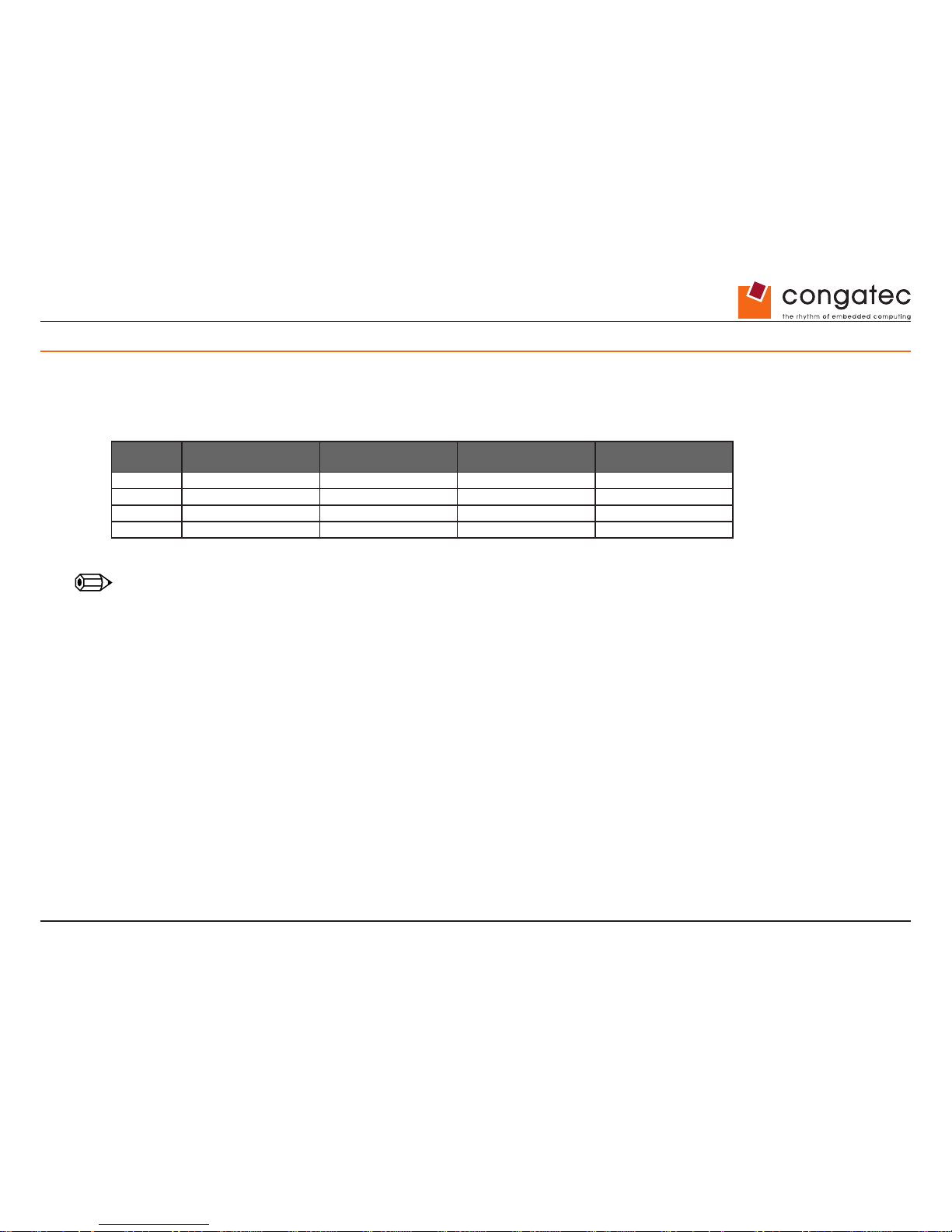
The graphics engine of the conga-IGX supports maximum 2 independent displays, following combinations are possible:
Cong# DisplayPort V1.2
Maximum 3840 x 2160
LVDS
Maximum 1920 x 1200
DVI-I (digital)
Maximum 1920 x 1200
DVI-I (analog VGA)
Maximum 1920 x 1200
1 X X
2 X X (see note below)
3 X X
4 X X (see note below)
Note
Via DVI-I to VGA converter
Simultaneous use of DisplayPort and onboard LVDS is not possible; the appropriate G-series video channel can only be used exclusively for
DisplayPort (=LVDS disabled in BIOS Setup) or for LVDS (=LVDS enabled in BIOS Setup).
The DisplayPort output can be converted to a HDMI output, VGA output or (second) DVI output (appropriate converter required).
Windows 8 mode (=Secure Boot enabled) & LVDS support should only be used for BIOS revision R1.1.0, otherwise any graphics output may
be disabled. In case this happens, Setup Defaults should be enabled (see section Miscellaneous - BIOS/CMOS Reset).
Page 24
Copyright © 2014 congatec AG IGX1m02 24/134
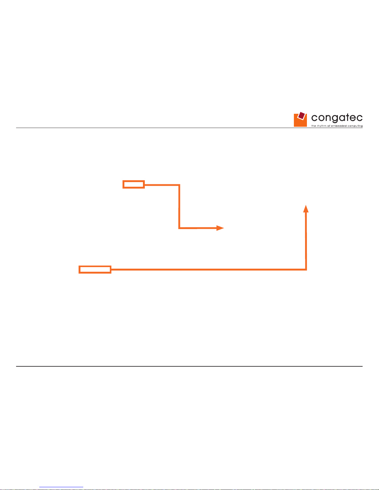
5.2 LVDS Display & Backlight Inverter Connection
Backlight Inverter
Integrated Backlight
powered by Inverter
Page 25
Copyright © 2014 congatec AG IGX1m02 25/134
5.3 LVDS Connector details
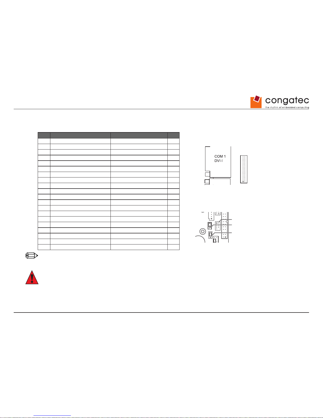
LVDS Connector: Hirose DF13-40 (or compatible).
PIN SIGNAL SIGNAL PIN
2 Ground Ground 1
4 LVDS_H3+ (EVEN_3+) LVDS_L3+ (ODD_3+) 3
6 LVDS_H3- (EVEN_3-) LVDS_L3- (ODD_3-) 5
8 Ground Ground 7
10 LVDS_H2+ (EVEN_2+) LVDS_L2+ (ODD_2+) 9
12 LVDS_H2- (EVEN_2-) LVDS_L2- (ODD_2-) 11
14 Ground Ground 13
16 LVDS_H1+ (EVEN_1+) LVDS_L1+ (ODD_1+) 15
18 LVDS_H1- (EVEN_1-) LVDS_L1- (ODD_1-) 17
20 Ground Ground 19
22 LVDS_H0+ (EVEN_0+) LVDS_L0+ (ODD_0+) 21
24 LVDS_H0- (EVEN_0-) LVDS_L0- (ODD_0-) 23
26 Ground Ground 25
28 LVDS_CLK_H+ (CLK_EVEN_+) LVDS_CLK_L+ (CLK_ODD_+) 27
30 LVDS_CLK_H- (CLK_EVEN_-) LVDS_CLK_L- (CLK_ODD_-) 29
32 Ground Ground 31
34 DDC-Data DDC-Clock 33
36 LCD-Power (see note below) LCD-Power (see note below) 35
38 Ground LCD-Power (see note below) 37
40 LCD_Power_Enable Ground 39
Note
Selectable via jumper.
Caution
Maximum load: 1A per pin.
Power
LVDS
CPU
Memory Module 1
Memory Module 2
USB 2.0
Drive Power
COM 3
LPT
Front Panel
LVDS
Backlight
Memory Module 1
Memory Module 2
LVDS Supply Settings
USB 2.0
LVDS BL Control Settings
Page 26
Copyright © 2014 congatec AG IGX1m02 26/134
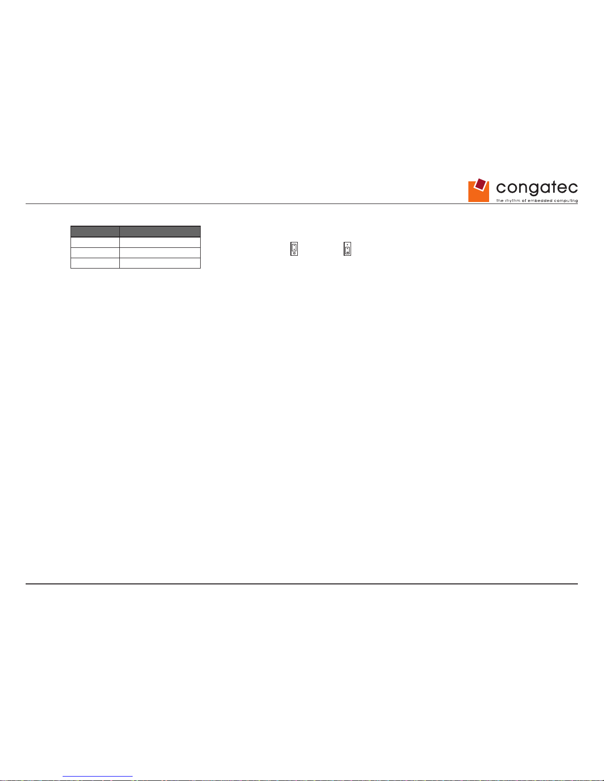
LVDS operating voltage jumper selector:
Pin Signal
1 VCC 5V
2 Power LVDS
3 VCC 3.3V
Drive Power
COM 3
LPT
Front Panel
FAN 2
Memory Module 1
BIOS Recovery Settings
LVDS Supply Settings
USB 2.0
LVDS BL Control Settings
System Power On Settings
LVDS Supply Settings
LVDS BL Control Settings
VCC 3.3 V
(default)
VCC 5 V
Analog
(default)
PWM
Page 27
Copyright © 2014 congatec AG IGX1m02 27/134
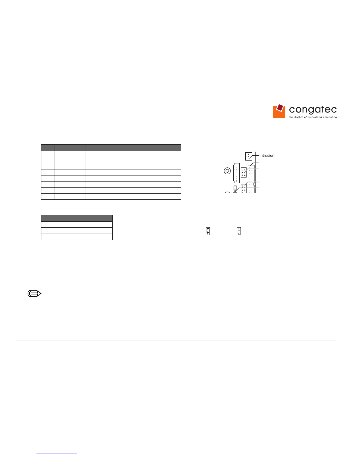
5.4 Backlight Inverter Connector Details
Backlight Inverter Connector: JST PHR-8
Pin Signal Comment
1 GND Ground
2 GND Ground
3 0-4V or PWM Backlight Brightness CTRL
4 VCC Power 5V
5 VCC Power 5V
6 BL On/Off Backlight On/Off Control
7 +12V Power 12V
8 +12V Power 12V
LVDS Backlight Brightness Control Jumper (Select analog or PWM output)
Pin Signal
1 PWM
2 BL Brightn. Contr.
3 VCC 3.3V
Backlight Brightness Control:
Provides a variable DC voltage between 0V and 4V via an RC lter (10kOhm / 20uF; buffered output). Alternatively, a 3.3V PWM signal
is available, see related jumper setting. Basically the LVDS brightness level can be selected by BIOS Setup, but it is also accessible from
Windows OS (Control Panel – Power Options – Screen Brightness). Access depends on appropriate setting in BIOS Setup. If this control signal
is used, the system integrator is responsible for the implementation of a backlight converter that ts to the control output voltage range.
Backlight On/Off Control: Active High, 3.3V
Note
Polarity can be changed via BIOS Setup.
Drive Power
COM 3
LPT
Front Panel
LVDS
Backlight
Memory Module 1
USB 2.0
LVDS BL Control Settings
Drive Power
COM 3
LPT
Front Panel
FAN 2
Memory Module 1
BIOS Recovery Settings
LVDS Supply Settings
USB 2.0
LVDS BL Control Settings
System Power On Settings
LVDS BL Control Settings
Analog
(default)
PWM
Page 28
Copyright © 2014 congatec AG IGX1m02 28/134
5.5 LVDS Timing & Screen Resolution
There are 9 default LVDS settings available:
• BIOS Setup Advanced - LVDS Cong Select
Note
Option 10 (LVDS adjusted Parameters) becomes visible after once running the “LVDS Tool” for implementing customized LVDS settings.
“Non-EDID Support” must be set to <Enabled> for standard LVDS displays without DDC (EDID) interface.
Page 29
Copyright © 2014 congatec AG IGX1m02 29/134
LVDS Mode:
The correct mode (FPDI/LDI) must be set for the attached LVDS panel.
Note
This setting is also required if customized LVDS timings are implemented
(LVDS tool).
Page 30
Copyright © 2014 congatec AG IGX1m02 30/134
LVDS Brightness Control:
Select if the LVDS backlight brightness is controlled by BIOS or by the OS.
LVDS Brightness:
Set the level for the LVDS backlight brightness for “BIOS controlled” mode.
1 = minimum voltage level (0V) resp. minimum PWM level
255 = maximum voltage level (4V) resp. maximum PWM level
Page 31
Copyright © 2014 congatec AG IGX1m02 31/134
POST Screen Mode:
Default setting = Graphic Mode (800 x 600)
For panels, 800 x 600 mode should be changed
to <Text Mode> in order to enable full BIOS
POST screen as well as the BIOS Setup screen
(otherwise some portions of the screen may not
be visible).
Page 32
Copyright © 2014 congatec AG IGX1m02 32/134
5.6 LVDS Tool
Note
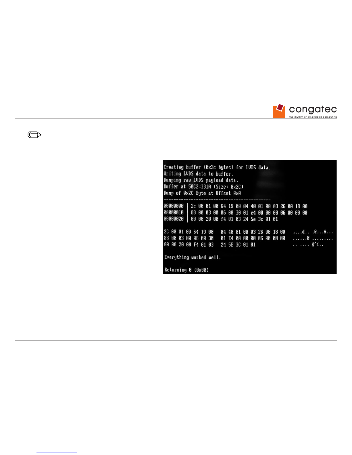
The LVDS tool (DOS-based) allows ashing specic LVDS settings to the system BIOS of the conga-IGX. The LVDS tool needs a panel-specic
EDID conguration le based on the specication data of the LVDS panel. Sample conguration EDID les are available in the LVDS Tool kit.
(Sample screen message after running LVDS tool)
For adjusting EDID les the “Phoenix EDID tool” is required
and can be downloaded from the congatec website.
Page 33
Copyright © 2014 congatec AG IGX1m02 33/134
5.7 LVDS Cabling Reference
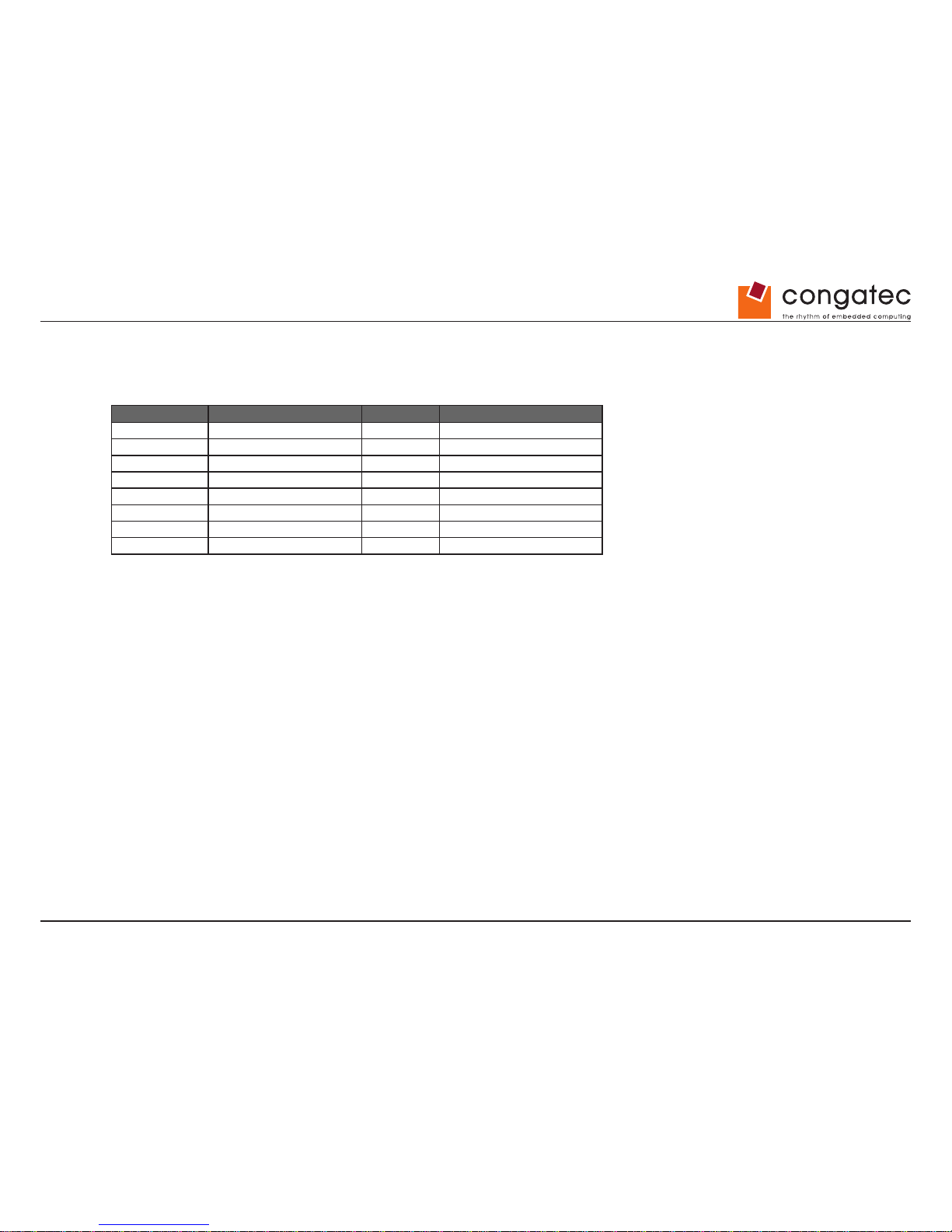
congatec does not provide LVDS cables. The user must create their own LVDS cables. Sample cabling diagrams for the following LVDS
displays and related inverters are available at www.congatec.com
Display Size TFT Pixel Inverter
10.4” NEC NL6448BC33-63D 640x480 NEC104PW201
12.1” AUO G121SN01-V0 800x600 Green-C&C GH093A
12.1” LG-Philips LB121S03-TL01 800x600 Green-C&C GH001HB
15” Sharp LQ150x1LW71N 1024x768 TDK CXA-0349
15” AUO G150XG01V0 1024x768 Green-C&C GH001A
17” AUO M170EG01-VD 1280x1024 Green-C&C GH053A
19” Sharp LQ190E1LW01 1280x1024 Power Systems PS-DA0412-05
19” AUO M190EG01 1280x1024 CH053(A1)
Page 34
Copyright © 2014 congatec AG IGX1m02 34/134
5.8 Dual-DVI Output
DVI Monitor 1
DVI Monitor 2
DisplayPort to DVI
Converter Cable
Dual Independent Display/Extended Desktop
Page 35
Copyright © 2014 congatec AG IGX1m02 35/134
5.9 VGA Output
Analog (VGA) Monitor
DVI/VGA Interface
Connector
Page 36
Copyright © 2014 congatec AG IGX1m02 36/134
5.10 DVI or VGA plus LVDS
DVI Monitor
Analog VGA Monitor via DVI/
VGA Interface Connector
LVDS Panel
Digital (DVI) monitor or analog (VGA) monitor via DVI/VGA interface connector plus
internal LVDS Display. Dual Independent Display/Extended Desktop
Dual channel 24-bit LVDS support.
Maximum pixel rate: 138.2M
Maximum LVDS screen resolution: 1920 x 1200 @ 60Hz
Page 37
Copyright © 2014 congatec AG IGX1m02 37/134
5.11 Internal & External graphics use in parallel
DVI Monitor
DVI
DVI
DVI
DisplayPort or DVI
(via Converter Cable)
DVI Monitor
DVI Monitor
DisplayPort or DVI Monitor
Note: This is a PCIe x4 slot, not a
PEG slot.
Note: Maximum power consumption of PCIe
graphics controller must be considered.
PCIe graphics controller
Page 38
Copyright © 2014 congatec AG IGX1m02 38/134
6 Power Supply Features
6.1 12V / 19-24V DC Connector
Internal and external DC input can be powered by 12V or 19-24V (auto range switching).
Caution
Internal and external DC input must never be powered simultaneously.
Input current for external DC connector: maximum 5A, maximum 60W @ 12V, maximum 100W @ 19-24V
Recommended plug for external AC adapter:
• Ø 2.5mm / 5.5mm
• contact length ~ 10-11mm
• Angle plug or straight plug
Drive Power
COM 3
LPT
Front Panel
FAN 2
DC Plug
Jumper Settings
1 = + DC
2 = GND
12 V max. 60 Watt
19-24 V max. 100 Watt
Plug: 2.5 / 5.5 / 11 mm
Power 1 = GND
2 = GND
3 = + DC 12 / 19-24 V
4 = + DC 12 / 19-24 V
mSATASATA0 SATA1
LVDS
Backlight
TPM GPIO
Buzzer
Battery
2x USB 2.0
CPU
Memory Module 1
Memory Module 2
BIOS Recovery Settings
LVDS Supply Settings
USB 2.0
LVDS BL Control Settings
System Power On Settings
1
4
2
3
2
1
BIOS Recovery Settings
Normal Operation (default)
LVDS Supply Settings
LVDS BL Control Settings
VCC 3.3 V
(default)
VCC 5 V
Analog
(default)
PWM
Page 39
Copyright © 2014 congatec AG IGX1m02 39/134
6.2 Requirements for 12V / 19-24V operation
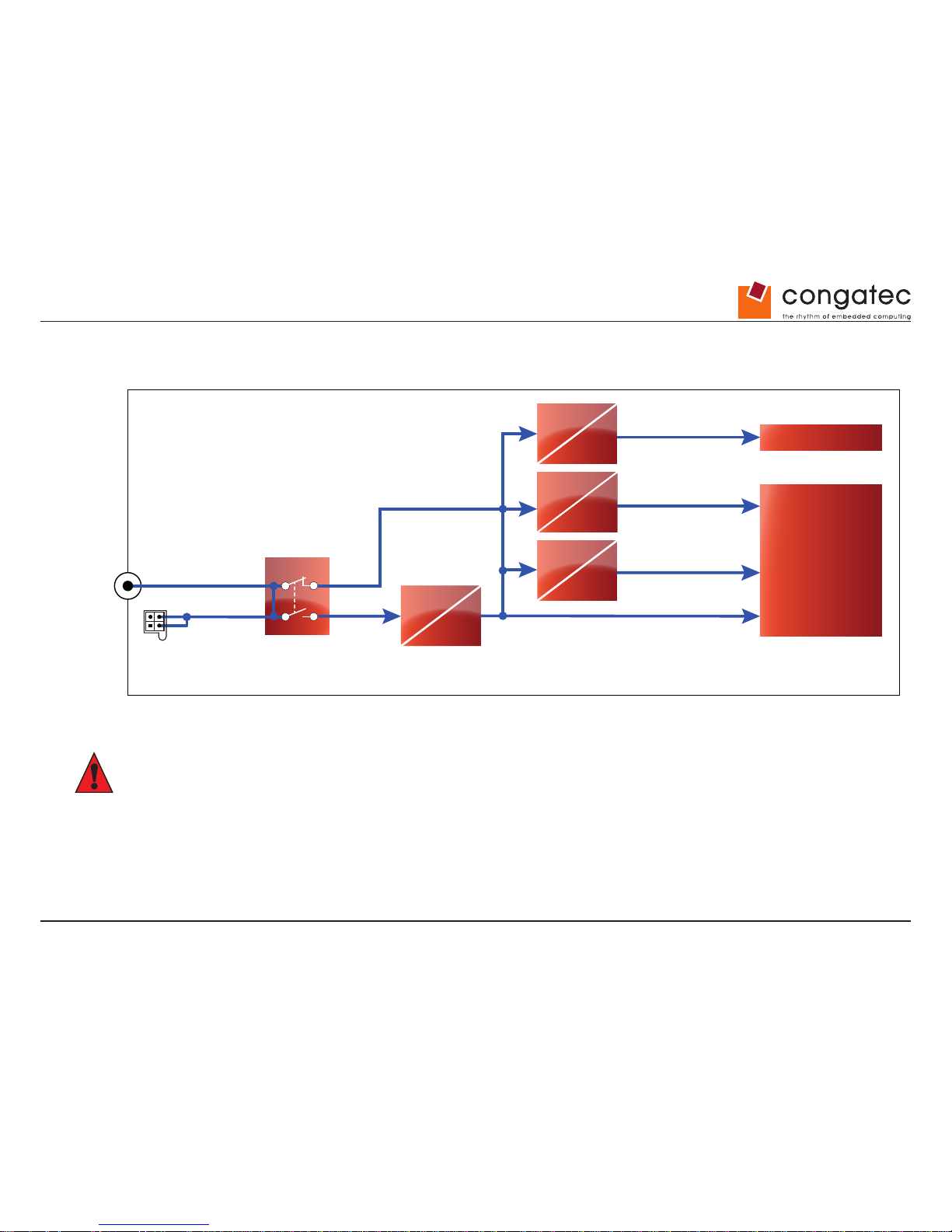
Simplied functional diagram for major onboard voltage converters
Auto Input
Voltage Range
Switch
Internal DC
Connector
max. 8A
External DC
Connector
max. 5A
CPU
Other
Devices
Core Voltage max. 25 W
5 V max. 4.5 A
12 V max. 4.5 A19-24 V12, 19-24 V
12, 19-24 V
12 V
3.3 V max. 5 A
DC
DC
DC
DC
DC
DC
DC
DC
“Other Devices” = any device that can be attached to the conga-IGX, such as fans, internal/external USB devices, (Mini-) PCIe controllers,
mSATA modules, LVDS display + inverter, drives, GPIO devices etc.
Caution
Overall conga-IGX input power must never exceed 100W.
Page 40
Copyright © 2014 congatec AG IGX1m02 40/134
6.3 Power option for internal devices
6.3.1 Requirements for DC operation
Nominal operating range 12V or 19 - 24V
Maximum operating range 12V [+/- 10%] or 19 - 24V [+ 10% - 15%]
Ripple/noise max. 400mV (PP)
Maximum input current: 5A (external)/8A (internal)
The DC power supply input provides a capacitive load of 700µF, which has to be covered by the AC adapter respectively the DC source during
power ramp-up.
6.3.2 Limited conga-IGX output current
The maximum conga-IGX output power available via (Mini-) PCIe- connector, fan-connectors, USB-connectors, GPI/O, LVDS/backlight
connector, and drive power connector is limited.
Maximum overall output current for each voltage:
• +3.3V / 5A
• +5V / 4.5A
• +12V / 4.5A
Caution
conga-IGX input power must never exceed 100W.
Page 41
Copyright © 2014 congatec AG IGX1m02 41/134
6.4 Drive Power Connector
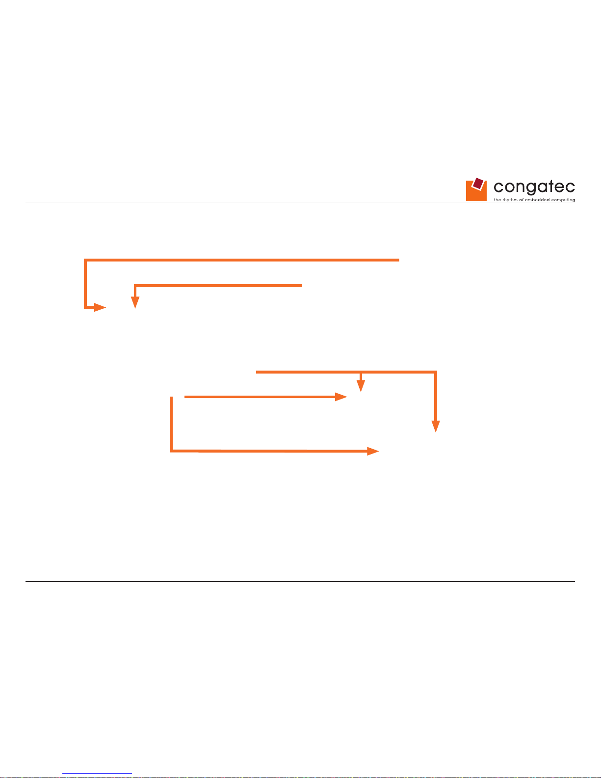
12/19-24 V DC
12/19-24 V DC
Data
Power
Data
Maximum rating via Drive Power Connector:
• +5V/2A
• +12V/2A
Page 42
Copyright © 2014 congatec AG IGX1m02 42/134
6.5 Drive Power Connector
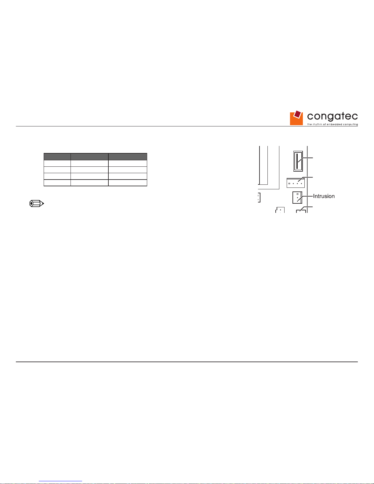
Pin Signal Comment
1 VCC (+5V) max. 2A
2 GND
3 GND
4 +12V max. 2A
Note
Onboard connector is compliant to standard oppy power supply connector.
Drive Power
LPT
LVDS
Backlight
Memory Module 1
USB 2.0
Page 43
Copyright © 2014 congatec AG IGX1m02 43/134
7 Internal Connectors
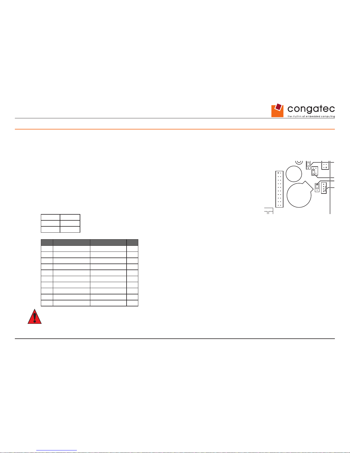
7.1 Feature Connector
8 bit 3.3V General Purpose Input/Output (GPIO) in order to attach any digital device or LEDs. Feature Connector provides additional power for
internal devices (3.3V; 5V; 12V; 5Vaux; max. 1.5A per pin)
Connector Type: CompuPack R-DRK2-20-S3-SMT
Limited conga-IGX output current:
The maximum conga-IGX output power available via (Mini-) PCIe- connector, fan-connectors, USB-connectors,
GPI/O, LVDS/backlight-connector, and drive power connector is limited.
Maximum overall output current for each voltage:
+3.3V 5A
+5V 4.5A
+12V 4.5A
Pin Signal Signal Pin
1 GPI/O_0 GPI/O_1 2
3 GPI/O_2 GPI/O_3 4
5 GPI/O_4 GPI/O_5 6
7 GPI/O_6 GPI/O_7 8
9 VCC_3.3V GND 10
11 VCC_3.3V VCC_5Vaux 12
13 reserved GND 14
15 reserved GND 16
17 GND VCC_5V 18
19 VCC_12V VCC_12V 20
Caution
Maximum current per power pin is 1.5A.
Drive Power
COM 3
LPT
Front Panel
FAN 2
LVDS
Backlight
GPIO
Buzzer
Battery
2x USB 2.0
Memory Module 1
Memory Module 2
BIOS Recovery Settings
LVDS Supply Settings
USB 2.0
LVDS BL Control Settings
System Power On Settings
Page 44
Copyright © 2014 congatec AG IGX1m02 44/134
Parameter Range
GPI/O Input Low Voltage -0.5V … 0.8V
GPI/O Input High Voltage 2V … 3.3V
GPI/O Output Low Voltage max. 0.7V
GPI/O Output High Voltage min. 2.5V
Note
Maximum load per GPI/O pin: 10mA (overall current for all GPI/O pins must be < 85mA) Each GPI/O pin has an integrated serial resistor of 150
Ohm. GPIO access is provided via the SM-Bus controller PCA9554A. SM-Bus address: 0x78h (8-bit).
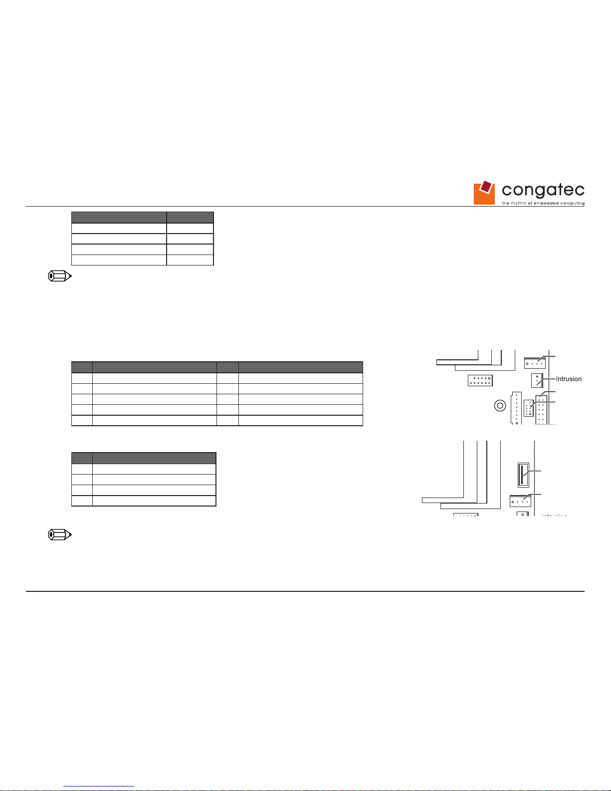
7.2 Internal USB 2.0 Ports
Pin Signal Pin Signal
1 VCC AUX 2 VCC AUX
3 Data negative Port X 4 Data negative Port Y
5 Data positive Port X 6 Data positive Port Y
7 GND 8 GND
9 Key 10 Not connected
Pin Signal
1 VCC auxiliary
2 Data negative
3 Data positive
4 GND
Fused with polyswitch and power supervision with over current detection
Note
External USB sticks may cause EMI/ESD issues. This can be avoided by using the internal USB port for the affected stick.
Drive Po
wer
COM 3
LPT
LVDS
Backlight
2x USB 2.0
Memory Module 1
Memory Module 2
USB 2.0
Drive Power
Memory Module 1
Memory Module 2
USB 2.0
Page 45
Copyright © 2014 congatec AG IGX1m02 45/134
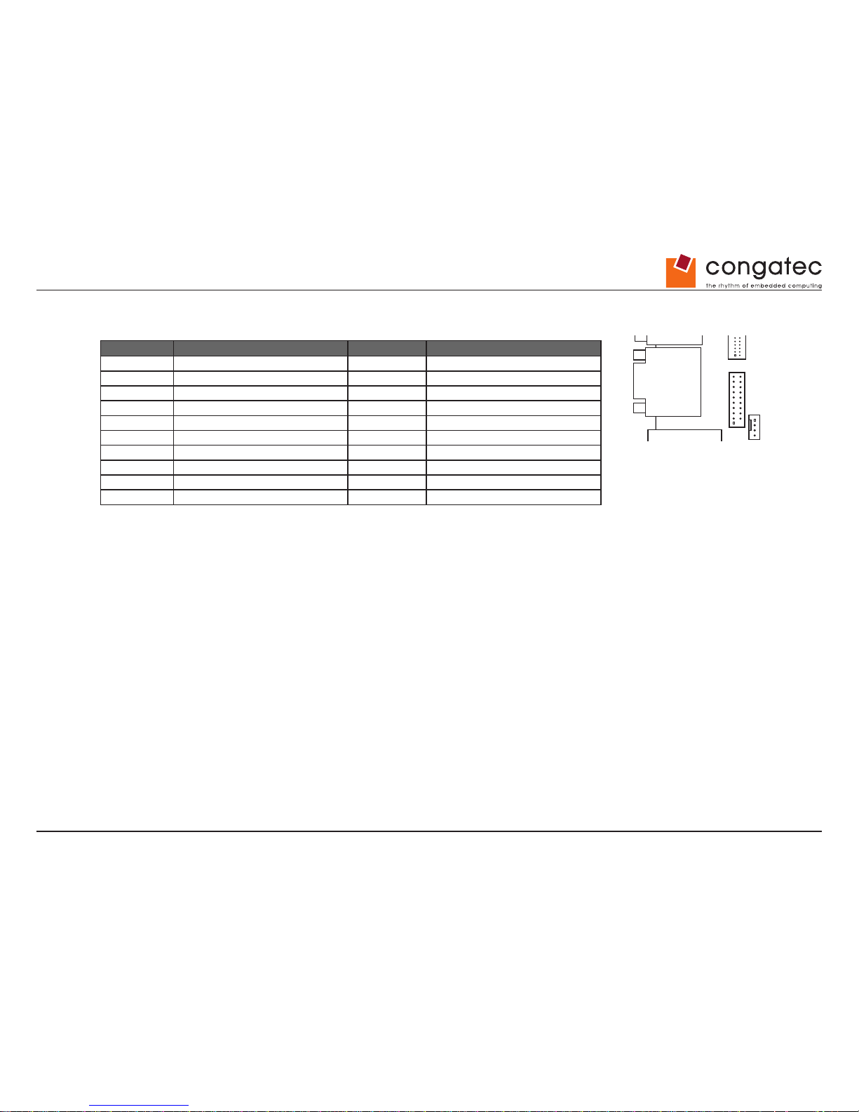
7.3 Internal USB 3.0 Ports
Pin Signal Pin Signal
1 VCC AUX 2 USB3_RX negative (P2)
3 USB3_RX positive (P2) 4 GND
5 USB3_TX negative (P2) 6 USB3_TX positive (P2)
7 GND 8 Data negative (P2)
9 Data positive (P2) 10 FP Detect
11 Data positive (P3) 12 Data negative (P3)
13 GND 14 USB3_TX positive (P3)
15 USB3_TX negative (P3) 16 GND
17 USB3_RX positive (P3) 18 USB3_RX negative (P3)
19 VCC AUX 20 <Key>
Drive Power
LPT
Power
COM 2
DisplayPort
FAN 1
mSATASATA0 SATA1
LVDS
Backlight
2x USB 3.0
2x USB 2.0
LVDS
CPU
Memory Module 1
Memory Module 2
USB 2.0
Page 46
Copyright © 2014 congatec AG IGX1m02 46/134
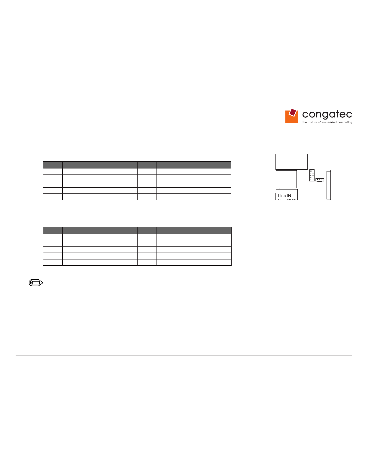
7.4 Internal Audio Ports – Front panel Audio
Operating mode (High Denition Audio or Legacy Audio) selectable in BIOS Setup.
High Denition Audio:
Pin Signal Pin Signal
1 HDA Port 1 Left 2 Analog GND
3 HDA Port 1 Right 4 FP Presence Detect
5 HDA Port 2 Left 6 Jack Sense Port 1
7 Jack Sense common 8 Key
9 HDA Port 2 Right 10 Jack Sense Port 2
Legacy Audio (AC97):
Pin Signal Pin Signal
1 Mic Left 2 Analog GND
3 Mic Right 4 reserved
5 Headphone out Right 6 reserved
7 Analog GND 8 Key
9 Headphone out Left 10 reserved
Note
When using this connector in AC97/Legacy mode pay attention to pin 7. This pin is tied to GND. HP_ON# signaling on this pin is not supported.
Drive Power
COM 3
LPT
Front Panel
Mouse
Keyboard
Power
COM 2
DisplayPort
FAN 2
FAN 1
SPDIF
Front Audio
mini PCIe
mSATASATA0 SATA1
LAN
2x USB 2.0
LAN
2x USB 2.0
LVDS
Backlight
TPM GPIO
Buzzer
Battery
2x USB 3.0
2x USB 2.0
LVDS
CPU
Memory Module 1
Memory Module 2
BIOS Recovery Settings
LVDS Supply Settings
USB 2.0
LVDS BL Control Settings
System Power On Settings
Page 47
Copyright © 2014 congatec AG IGX1m02 47/134
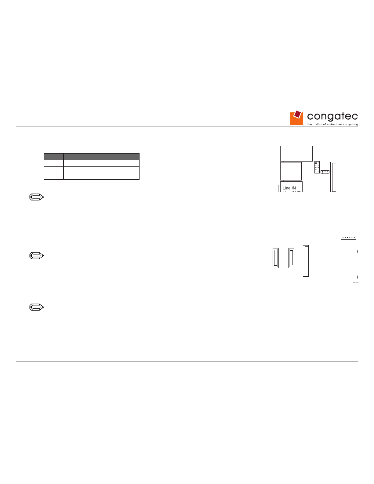
7.5 Internal Audio Ports - SPDIF
Pin Signal
1 VCC
2 SPDIF out
3 GND
Note
Standard connector bracket should directly connect to SPDIFout and GND pins (no signal converter required).
7.6 m-SATA / SATA
Fullsize m-SATA socket
Supports modules with SATA interface.
Note
Mini-PCI-Express or USB is NOT supported by this interface.
Two SATA 3.0 connectors (up to 6Gb/s).
Layout prepared for SATA Disk-On-Module (powered via external power cable only).
Note
SATA-1 and mSATA are shared and can not be used simultaneously.
Drive Power
COM 3
LPT
Front Panel
Mouse
Keyboard
Power
COM 2
DisplayPort
FAN 2
FAN 1
SPDIF
Front Audio
mini PCIe
mSATASATA0 SATA1
LAN
2x USB 2.0
LAN
2x USB 2.0
LVDS
Backlight
TPM GPIO
Buzzer
Battery
2x USB 3.0
2x USB 2.0
LVDS
CPU
Memory Module 1
Memory Module 2
BIOS Recovery Settings
LVDS Supply Settings
USB 2.0
LVDS BL Control Settings
System Power On Settings
Drive Power
COM 3
LPT
Front Panel
mSATASATA0 SATA1
LVDS
Backlight
2x USB 2.0
CPU
Memory Module 1
Memory Module 2
LVDS Supply Settings
USB 2.0
LVDS BL Control Settings
Page 48
Copyright © 2014 congatec AG IGX1m02 48/134
7.7 Mini-PCIe Connector
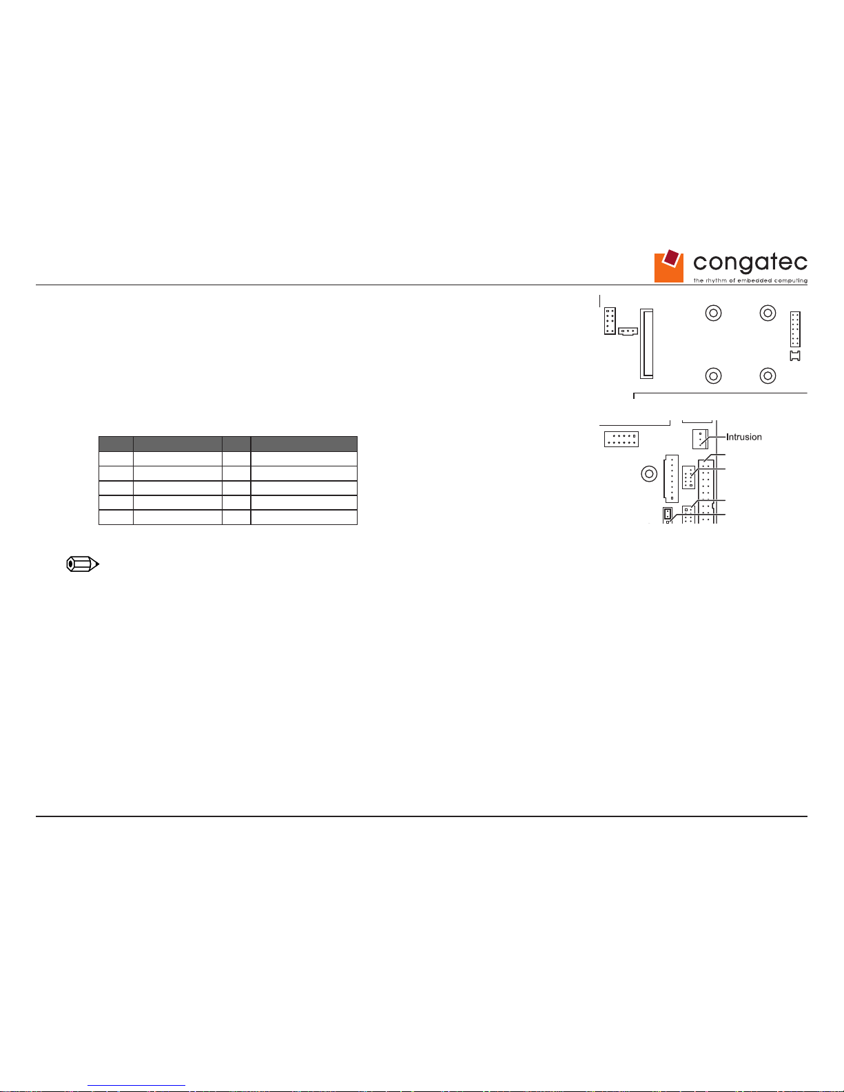
Mini-PCI Express (Gen2) connector Prepared for halfsize and fullsize modules,
including USB 2.0 interface
7.8 Internal Serial Connector (COM3)
Pin Signal Pin Signal
1 DCD 3 2 DSR 3
3 SIN 3 4 RTS 3
5 SOUT 3 6 CTS 3
7 DTR 3 8 RI 3
9 GND 10 Key
Note
Internal serial port = COM3
Drive Power
COM 3
LPT
Front Panel
Power
FAN 2
FAN 1
SPDIF
Front Audio
mini PCIe
mSATASATA0 SATA1
LVDS
Backlight
TPM
GPIO
Buzzer
Battery
2x USB 3.0
2x USB 2.0
LVDS
CPU
Memory Module 1
Memory Module 2
BIOS Recovery Settings
LVDS Supply Settings
USB 2.0
LVDS BL Control Settings
System Power On Settings
Drive Power
COM 3
LPT
Front Panel
LVDS
Backlight
Memory Module 1
Memory Module 2
USB 2.0
LVDS BL Control Settings
Page 49
Copyright © 2014 congatec AG IGX1m02 49/134
7.9 Internal Parallel Port Connector
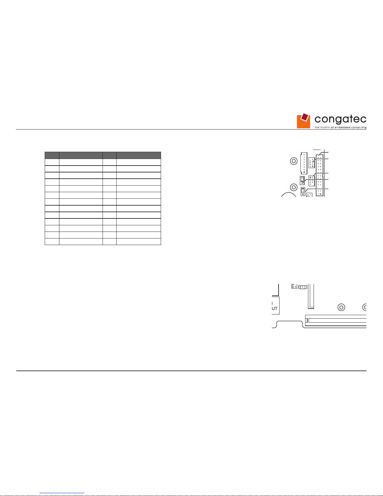
Pin Signal Pin Signal
1 Strobe 2 AutoFD
3 Data0 4 Error
5 Data1 6 Init
7 Data2 8 Sel_L
9 Data3 10 GND
11 Data4 12 GND
13 Data5 14 GND
15 Data6 16 GND
17 Data7 18 GND
19 ACK 20 GND
21 Busy 22 GND
23 Empty 24 GND
25 Select 26 GND
7.10 PCI Express Extension Slot
PCIe x4 (Gen2)
• Supports up to four PCIe lanes
• “open slot” including card mount for PCIe x16 cards
Drive Power
COM 3
LPT
Front Panel
LVDS
Backlight
Memory Module 1
Memory Module 2
LVDS Supply Settings
USB 2.0
LVDS BL Control Settings
Drive Power
COM 3
LPT
Front Panel
Power
PCIe X4
FAN 2
FAN 1
SPDIF
Front Audio
mini PCIe
mSATASATA0 SATA1
LVDS
Backlight
TPM GPIO
Buzzer
Battery
2x USB 3.0
2x USB 2.0
LVDS
CPU
Memory Module 1
Memory Module 2
BIOS Recovery Settings
LVDS Supply Settings
USB 2.0
LVDS BL Control Settings
System Power On Settings
Page 50
Copyright © 2014 congatec AG IGX1m02 50/134
7.11 Intrusion Connector
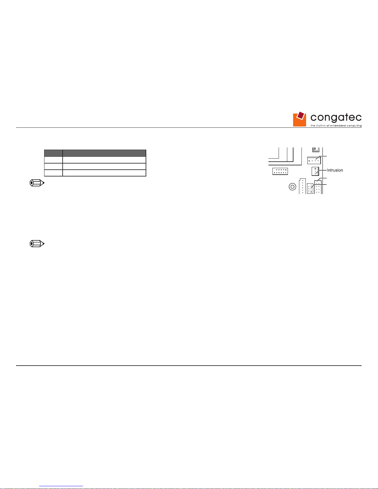
Pin Signal
1 GND
2 Case open (low asserted)
3 Intrusion switch present (low asserted)
Note
The intrusion supervision feature needs to be enabled in BIOS Setup rst (Menu “Security”/”Cabinet
Monitoring”). This BIOS option is only available if pin 3 (“Intrusion Switch Present”) is connected to
GND.
Chassis intrusion is active even if the system is switched off (S5 state) or disconnected from mains power. The intrusion event is monitored by
the chipset and stored in the BIOS Eventlog during the next Boot. A
timestamp (Boot date/time) will be added then.
Note
This timestamp does not represent date/time of the intrusion event.
If a Supervisor Password is enabled in BIOS Setup, the system will stop during BIOS POST if an intrusion event has been detected. In order
to continue, the Supervisor Password must be entered to conrm the intrusion event.
The intrusion status can be easily monitored by using the BMCAPI (Windows)
Drive Power
COM 3
LPT
LVDS
Backlight
Memory Module 1
Memory Module 2
USB 2.0
Page 51
Copyright © 2014 congatec AG IGX1m02 51/134
7.12 Fan Connector
Pin Signal
1 GND
2 12V in PWM mode / 4V-12V in 3-Pin mode
3 FAN Sense
4 FAN PWM
Note
Fan 1 (Processor) supports 4-wire “PWM” only.
Fan 2 (Chassis) can be used in 4-wire or 3-wire mode (BIOS Setup)
If a 3-wire fan is connected, but BIOS Setup is set to “4 wires” (= Default) the fan will
operate at full speed (12V).
In 3-wire mode, the default minimum operating voltage is set to ~ 4V.
Fan current must not exceed 1A per connector.
Minimum fan speed can be customized via SilentFanCong-Manager tool.
Note
TCV Version shows the BIOS internal version of the System Monitoring parameters. After they have been customized by the SilentFanCong
tool, the TCV Version in BIOS Setup is automatically changed to “OEM”.
Drive Power
COM 3
LPT
Front Panel
FAN 2
LVDS
Backlight
Buzzer
Battery
Memory Module 1
Memory Module 2
BIOS Recovery Settings
LVDS Supply Settings
USB 2.0
LVDS BL Control Settings
System Power On Settings
Page 52
Copyright © 2014 congatec AG IGX1m02 52/134
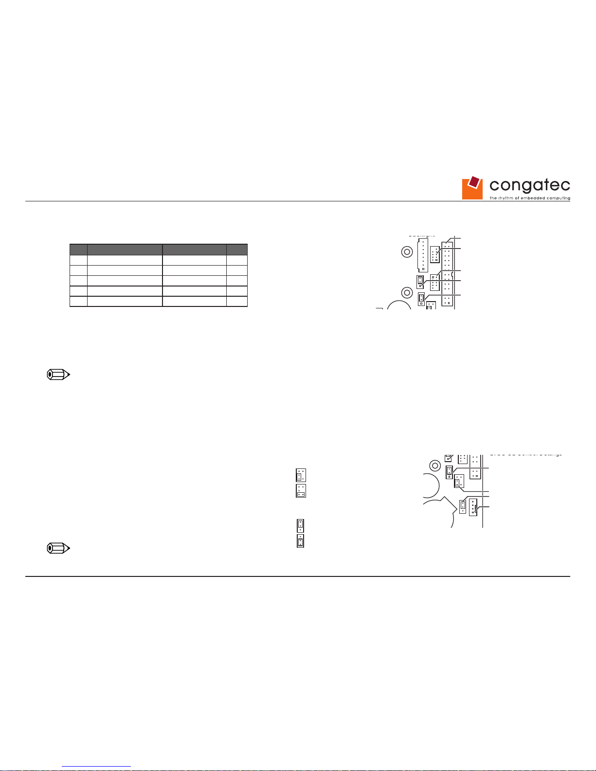
7.13 Front Panel Connector
Pin Signal Signal Pin
10 (KEY) Reserved (NC) 9
8 PowerSwitch_GND ResetSwitch_P 7
6 PowerSwitch_P ResetSwitch_GND 5
4 Power_LED_GND HDD_LED- 3
2 Power_LED+ HDD_LED+ 1
Frontpanel providing
• Powerswitch
• Power/HDD-LED
• Reset-Switch
Note
Pinning is compatible to Intel 10 pin header
Power LED / HDD LED: Constant current, typ. 3mA.
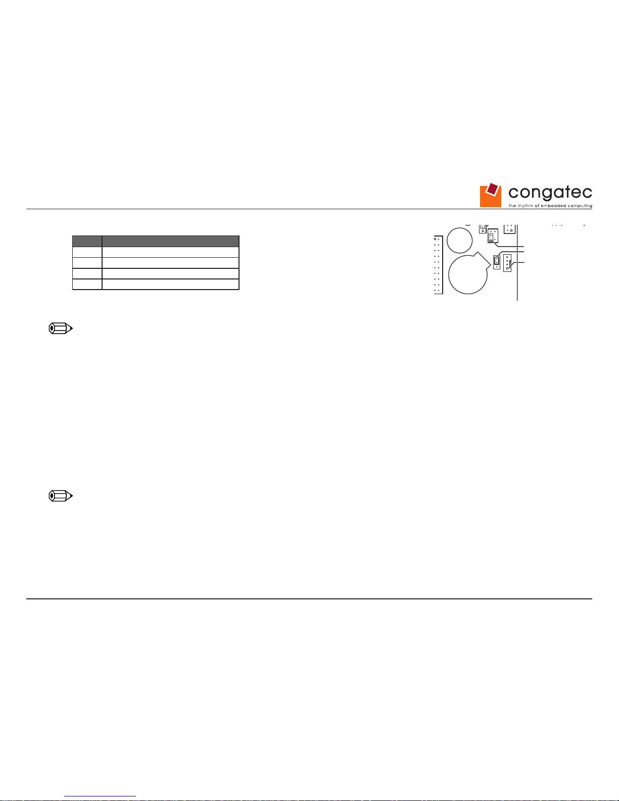
7.14 Additional Jumper Settings
BIOS Recovery Jumper:
• BIOS Recovery/Reset BIOS Setup to Defaults
System Power-On Jumper (“ALWON”):
• Forced “Always-Power-On” Setting
System will switch on automatically when connected to power
even if the battery is empty or damaged no explicit need for
system power button.
Note
Power-on may be delayed for several seconds.
Drive Power
COM 3
LPT
Front Panel
LVDS
Backlight
Memory Module 1
Memory Module 2
LVDS Supply Settings
USB 2.0
LVDS BL Control Settings
Drive Power
COM 3
LPT
Front Panel
FAN 2
LVDS
Backlight
Battery
Memory Module 1
BIOS Recovery Settings
LVDS Supply Settings
USB 2.0
LVDS BL Control Settings
System Power On Settings
Drive Power
COM 3
LPT
Front Panel
FAN 2
BIOS Recovery Settings
LVDS Supply Settings
USB 2.0
LVDS BL Control Settings
System Power On Settings
BIOS Recovery Settings
Normal Operation (default)
Normal Operation (default)
LVDS Supply Settings
LVDS BL Control Settings
System Power On Settings
Always on
BIOS Recovery / Reset to Defaults
VCC 3.3 V
(default)
VCC 5 V
Analog
(default)
PWM
Page 53
Copyright © 2014 congatec AG IGX1m02 53/134
8 System Monitoring
8.1 conga-IGX: Fans
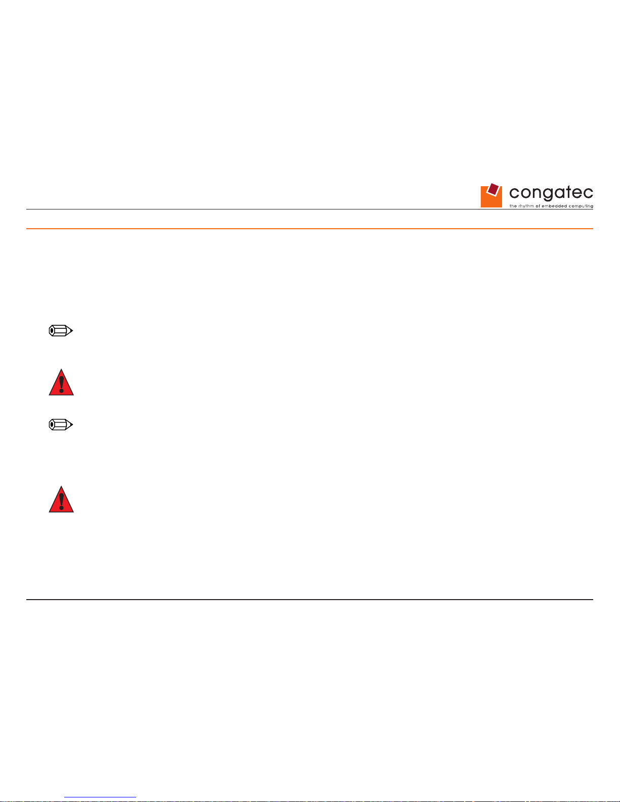
TDPmax - Processor (SoC):
• 9W AMD G-Series SOC GX-210HA
• 15W AMD G-Series SOC GX-217GA
• 25W AMD G-Series SOC GX-420CA
Note
Processor Throttling is enabled @ 108°C and disabled again below 105°C. Above 115°C the processor shuts down the system. The onboard
System Monitoring implementation provides a processor Alert above 105°C.
Caution
Fans must NOT be attached or removed while the system is powered, otherwise the conga-IGX may be damaged.
Note
Fan1 PWM (4-wire) only!
Fan2: PWM (4-wire) or voltage controlled (3-wire) possible.
Selectable via BIOS Setup
Caution
Do not attach more than one fan per connector (max. 1A per connector).
Page 54
Copyright © 2014 congatec AG IGX1m02 54/134
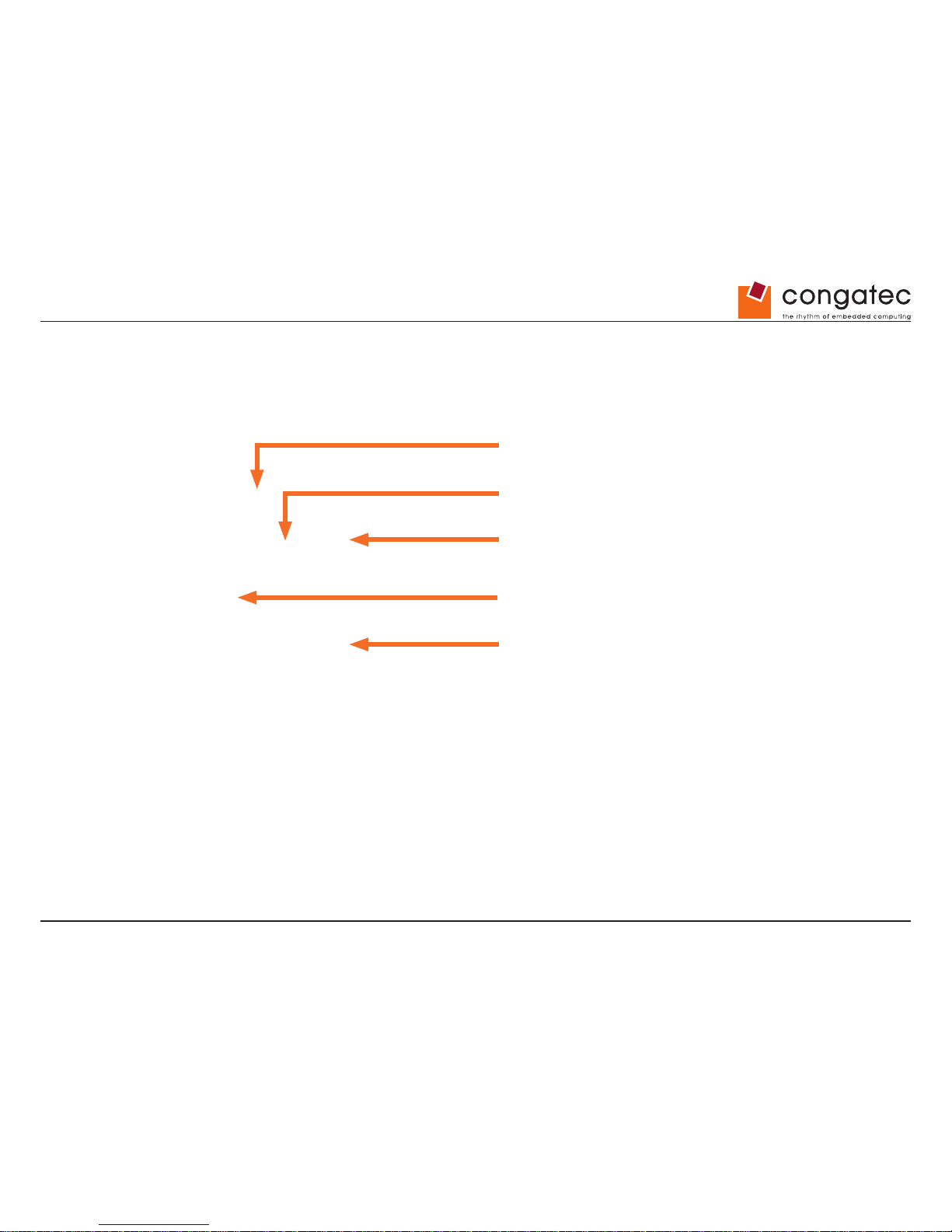
8.2 conga-IGX Sensors
Sensor 4 [Core]
(rear side below core voltage regulator coil )
Sensor 0 [AMD TSI]
(inside Processor)
Sensor 3 [Mem]
Sensor 2 [12VReg]
(close to 12V voltage regulator coil)
Sensor 1 [SIO]
(inside Super I/O)
Page 55
Copyright © 2014 congatec AG IGX1m02 55/134
8.3 SilentFanCongManager
Windows-based System Management Conguration Tool available for download
• Windows-based conguration tool (SilentFanCong) to create customized system monitoring settings like minimum fan speed and
temperature sensor inuence. These customized settings are stored in a specic “SMCO” ash le.
• DOS-based tool “SMCO” to ash the customized system monitoring settings (SMCO le) to the system BIOS of the target unit.
Note
New settings are written permanently to system BIOS. Any BIOS update or BIOS Recovery will not reset the new settings
Page 56
Copyright © 2014 congatec AG IGX1m02 56/134
8.4 Temperature Reference Points conga-IGX
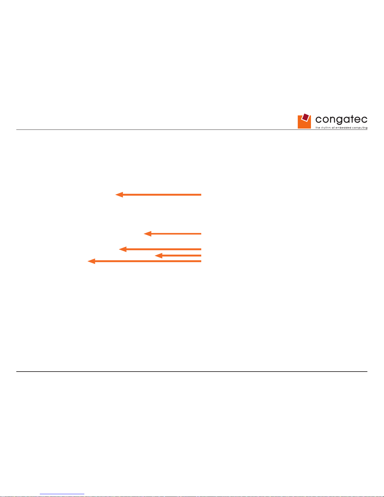
Operating Conditions: Circulating air maximum 60°C, Usage 24h/7 days
All voltage regulators (FETs) max. 90°C
All capacitor max. 68°C
All inductors max. 90°C
All Oszillators max. 70°C
Note: Battery operation is speci ed in temperature range up
to 60°C. Operation between 60°C and 70°C may result in:
• Higher self discharge rate
• Decline of speci ed characteristics
• Danger of leakage increases
SoC max. 90°C (chip surface)
Super I/O (SMSC) max. 70°C
Super I/O (Nuvoton) max. 70°C
Battery max. 60/70°C 1)
Audio Codec max. 70°C
Page 57
Copyright © 2014 congatec AG IGX1m02 57/134
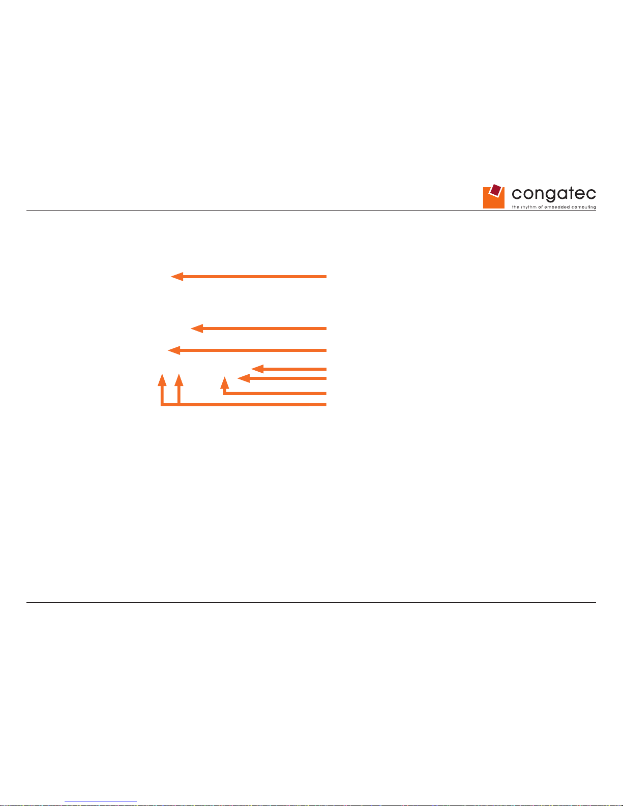
COM Driver max. 70°C
SATA Switch max. 80°C
DisplayPort/LVDS Switch max. 80°C
LVDS Converter max. 70°C
COM Driver max. 70°C
COM Driver max. 70°C
LAN Controller max. 70°C
Page 58
Copyright © 2014 congatec AG IGX1m02 58/134
9 Power Consumption
9.1 Sample Conguration
Typical mains power consumption:
Windows 7 - Idle Windows 7 – 100% Processor Load
conga-IGX1 < 4W (see note below) ~ 13W
conga-IGX2 < 4W (see note below) ~ 20W
conga-IGX3 ~ 4W ~ 29W
Note
During fanless operation.
Page 59
Copyright © 2014 congatec AG IGX1m02 59/134
10 Operating System Support
10.1 MS Windows / MS Windows Embedded Compact
MS Windows
• Windows 7 32bit / 64bit
• Windows 8.1 64bit
• SBC conga-IGX is designed according to the Microsoft Guidelines for MS Windows 7 and Windows 8.1
• MS certied drivers are available
MS Windows Embedded CE / Embedded Compact
• AMD plans to support Embedded CE6.0, Embedded Compact 7.0 and Embedded Compact 2013
• Evaluation drivers / SDK
10.2 Linux Support
Following distributions have been tested with “out of box”-drivers:
• Fedora 19
• Debian 7
• Ubuntu LTS 12.04
• OpenSUSE 13.1
• Redhat 6.5
USB keyboard/mouse issue during installation
Solved by kernel parameter “iommu=soft”
• Ubuntu Desktop 13.10
USB keyboard/mouse issue during installation
Solved by kernel parameter “iommu=soft”
Graphics issues (X server)
Workaround: Fallback vesa/fbdev or usage of AMD/ATI graphics driver
Page 60
Copyright © 2014 congatec AG IGX1m02 60/134
11 conga-IGX Tools
11.1 Common conga-IGX Tools
• BIOS Boot Logo Tool
Tool to integrate a customized boot logo
• EditCMOS
DOS-based production tool to change BIOS settings and freeze customized BIOS settings (= customized default settings)
• OEMIDENT
Production tool to add MS OEM licence data
(SLP2.x for Windows 7 and OA3 for Windows 8)
Add an individual customer serial no, add a chassis asset tag, and some more DMI data
• SilentFanCong-Manager
Windows-based conguration tool to implement customized fan characteristics and temperature parameters. Includes DOS-based tool
“SMCO” to ash the conguration le permanently into the system BIOS.
• Windows System-Monitoring API (BMCAPI)
BMC-Management-Controller to access and adjust System Monitoring parameters like fan speed and temperatures. This
API also
provides access to the conga-IGX watchdog, the 8Bit GPIO interface and the intrusion feature of the conga-IGX.
• Linux System-Monitoring Driver (“LM-Sensors”)
BMC-Management-Controller to access and adjust System Monitoring parameters like fan speed and temperatures. This driver also
provides access to the conga-IGX watchdog.
• LVDS Tool
Tool to adjust LVDS-timings for the conga-IGX. Adjusted data are ashed into the system BIOS permanently.
See section 5.6 of this document for details.
Page 61
Copyright © 2014 congatec AG IGX1m02 61/134
12 Miscellaneous
12.1 System Watchdog (WD)
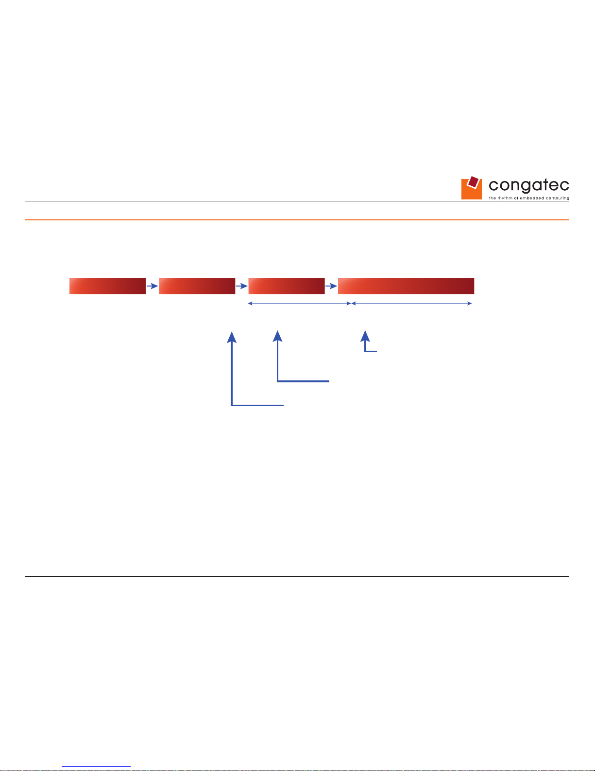
conga-IGX provides full Operating System Boot- and Operating System-Runtime HW Watchdog supervision.
Power On BIOS POST OS Boot OS running
BOOT-WD-timeout
(according to BIOS Setup)
BIOS Boot Watchdog OS Watchdog
OS-WD-timeout (max. 255 minutes)
(according to specific WD software agent)
OS started. If the watchdog has been enabled by BIOS (meout
set to xy minutes in BIOS Setup) it must be switched off or
retriggered (connuously) by a specific OS applicaon (=WD
soware agent), otherwise the system will be reset aer xy
minutes (= BOOT-WD-meout) respecvely aer nn minutes
(repeve OS-WD-meout).
If the watchdog is enabled in BIOS Setup (meout set to xy ≥ 1 minutes) and the
system hangs during OS boot, the system will be reset aer xy minutes.
If the watchdog is enabled in BIOS Setup (meout set to xy ≥ 1 minutes) and the system hangs
during OS boot, the system will be reset aer xy minutes.
Note:
Both watchdogs are physically idencal, but they are handled from different applicaon levels
How to handle the two watchdog levels
BIOS Boot Watchdog
Set Watchdog Timeout in BIOS Setup
0 = WD disabled
1 – 255 = WD enabled (timeout = 1 – 255 minutes)
Page 62
Copyright © 2014 congatec AG IGX1m02 62/134
OS Watchdog
Use “WD software agent” to stop or retrigger the watchdog during OS runtime
Note
This “agent” needs to be provided by the customer, dependent on his/her needs. For easy access to the watchdog functions, the Windows API
(BMCAPI) or the related Linux driver (lm-sensors) can be used.
12.2 Trusted Platform Module (TPM)
Optional module based on Inneon TPM V1.2
12.3 RealTime Clock (RTC) Accuracy
The onboard realtime clock is approved for an accuracy of +/-35ppm (= maximum 91sec deviation per month).
The RTC crystal itself is specied with +/-20ppm (= max. 52 second deviation per month). Each year of ageing adds around +/-3ppm on top
of this.
12.4 BIOS/CMOS Reset (“BIOS Setup Defaults”)
In order to reset the CMOS settings: Power off system, set related Jumper to “BIOS Recovery”, power on system and wait until picture appears
on screen. Power off again and set jumper to previous position. BIOS Setup should now be reset to default settings. For this procedure no BIOS
update is required!.
Drive Power
COM 3
LPT
Front Panel
FAN 2
mSATASATA0 SATA1
LVDS
Backlight
TPM
GPIO
Buzzer
Battery
2x USB 2.0
CPU
Memory Module 1
Memory Module 2
BIOS Recovery Settings
LVDS Supply Settings
USB 2.0
LVDS BL Control Settings
System Power On Settings
Drive Power
COM 3
LPT
Front Panel
FAN 2
LVDS
Backlight
Memory Module 1
BIOS Recovery Settings
LVDS Supply Settings
USB 2.0
LVDS BL Control Settings
System Power On Settings
BIOS Recovery Settings
Normal Operation (default)
LVDS Supply Settings
LVDS BL Control Settings
BIOS Recovery / Reset to Defaults
VCC 3.3 V
(default)
VCC 5 V
Analog
(default)
PWM
Drive Power
COM 3
LPT
Front Panel
FAN 2
LVDS
Backlight
Memory Module 1
BIOS Recovery Settings
LVDS Supply Settings
USB 2.0
LVDS BL Control Settings
System Power On Settings
Page 63
Copyright © 2014 congatec AG IGX1m02 63/134
13 Known Issues and Important Notes
13.1 Support for MS Windows XP
AMD recently announced to provide drivers for MS Windows XP. They are already available on the AMD developer web.
Note
There will be no ofcial release or support from congatec for these XP drivers.
13.2 Graphics Memory
In BIOS Setup, the graphics memory is set to 256MB (default). If there are 4GB Ram installed Windows 7 (32Bit) provides only 2.69 GB system
memory. In order to increase the available system memory, the graphics memory can be reduced to e.g. 128MB in BIOS Setup. In order to
increase the graphics performance (e.g. Blueray playback) the graphics memory can be increased to e.g. 512MB in BIOS Setup. Graphics
memory should be set to a xed value.
13.3 AMD “Eyenity” Support
Currently the AMD graphics driver does not yet provide support for Eyenity (e.g. combine two displays). Support is expected from June/2014.
13.4 HDMI Audio Support
HDMI audio transmission is not yet supported by the released driver.
An appropriate driver including HDMI support is expected from beginning of June 2014 (Driver version ≥14.20). In order to use HDMI audio in
advance, AMD provides a specic DVI-HMDI dongle (OPN: 199-999269).
13.5 Audio: Recording Level via HDA Front Panel
Recording via HDA audio front panel is very quiet. This hardware-related issue will be solved with the upcoming conga-IGX variants.
Page 64
Copyright © 2014 congatec AG IGX1m02 64/134
13.6 Video Playback (WMV, MP4)
There may be video frame glitches and data drops when running WMV- or MP4 les in 1080p resolution.
Issue seems to be related to used codec version and codec settings. Currently under investigation.
Page 65
Copyright © 2014 congatec AG IGX1m02 65/134
14 Introduction
BIOS Setup provides settings for system functions and the hardware conguration for the system. Any changes you make to the settings take
effect as soon as you save the settings and quit BIOS Setup. The individual menus in BIOS Setup provide settings for the following areas:
Main:
System functions
Advanced:
Advanced system conguration
Security:
Security functions
Power:
Energy saving functions
Event Logs:
Conguration and display of the event log
Boot:
Conguration of the start-up sequence
Save & Exit:
Save and quit
The setting options depend on the hardware conguration of your system. Some menus and certain settings may therefore not be available
in BIOS Setup on your
system, or the menus may be in a different place, depending on the BIOS revision.
14.1 Notational conventions
Pay particular attention to texts marked with this symbol. Failure to observe this warning endangers your health, destroys the system,
or may lead to loss of data. The warranty will be invalidated if the system becomes defective through failure to take notice of this
warning.
Indicates important information which is required to use the system properly.
► Indicates an activity that must be performed.
Indicates a result.
This font
Indicates data entered using the keyboard in a program dialogue or command line, e.g. your password ((Name123) or a
command used to start a program (start.exe).
This font
Indicates information that is displayed on the screen by a program, e.g.:
Installation is complete!.
Page 66
Copyright © 2014 congatec AG IGX1m02 66/134
This font
Indicates
•
terms and texts used in a software interface, e.g.: Click on Save.
•
names of programs or les, e.g. Windows or setup.exe.
Abc
Indicates a key on the keyboard, e.g:
F10
.
Page 67
Copyright © 2014 congatec AG IGX1m02 67/134
15 Navigating BIOS Setup
15.1 Open BIOS Setup
► Switch on the system.
Wait until the screen output appears.
► Press function key
F2
.
► If the system is password protected, you must now enter the password and conrm with the
Enter
key. You will nd details on password
assignment under “Password Description”, section 18.1.
The BIOS Setup Main menu will be displayed on the screen.
► To display system-specic information, select System Information and press the
Enter
key.
The BIOS release information will be displayed:
The revision of the BIOS (e.g. R1.4.0)
Under “Board” you will nd the system board number.
15.1.1 If you want to open the Boo t Menu immediately
You can use this function if you do not wish to boot y our system from the drive which is given as the rst setting under Boot Option Priorities
in the Boot menu.
► Start the system and wait until screen output appears.
► Press the function key
F12
.
On the screen, the boot options are shown as a popup window. You can now se lect the drive from which you wish to boot the operating
system. The selection options are the same as the possible settings given under Bo ot Option Priorities in the Boot submenu.
► Use the
and cursor keys to select which drive you want to boot the operating
system from now and conrm your choice with the
Enter
key.
Page 68
Copyright © 2014 congatec AG IGX1m02 68/134
Your selection is only valid for the current system boot. At the next system boot, the settings in the Boot menu a re valid again.
► If you want to start the BIOS Setup, use the cursor keys
or to select the
Enter Setup entry and conrm your selection with the
Enter
key.
15.1.2 If you wish to boot immediately from LAN
► Press the function key
F11
if you wish to boot directly via LAN and not from the drive which is given as the rst position under Boot
Option Priorities in the Boot menu.
15.2 Navigating BIOS Setup
or cursor keys
Select menu from menu bar
or cursor keys
Select eld - selected eld is highlighted
Enter or ESC keys
Open submenu (marked by ►) Enter and leave ESC
+ or - keys (numeric keypad=
Change entry for eld
F2 function key
Set default entries for all menus
F3 function key
Reset entries that were in use when BIOS Setup was opened
15.3 Exiting BIOS Setup
► Select the Save & Exit menu from the menu bar to end BIOS Setup.
You can then decide whether you want to save the changed settings.
► Select the required option.
► Press the Enter key.
Page 69
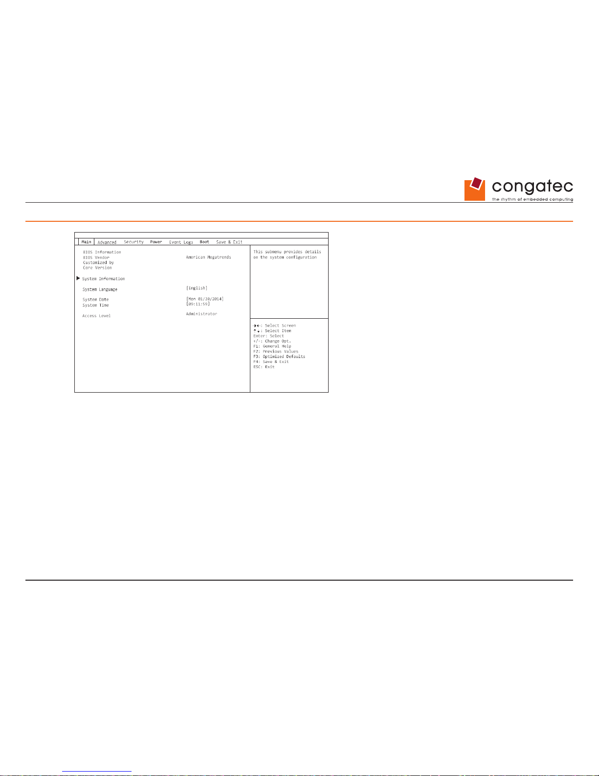
Copyright © 2014 congatec AG IGX1m02 69/134
16 Main Menu – System functions
Main Menu – System functions
Example showing the Main menu
The Main Menu is entered, to determine the basic system conguration and to provide an
overview. Some of the parameters are only
available under certain conditions.
16.1 System Information
This submenu contains descriptions of the system conguration. Some
parameters are only available optionally.
16.1.1 Board and Firmware Details
Shows the current information on the installed system board and rmware.
BIOS Revision
Shows the current BIOS version.
Build Date and
Time Shows the date and time of the formation of the current BIOS.
Page 70
Copyright © 2014 congatec AG IGX1m02 70/134
Board
Shows information about the current system board.
Ident Number
Shows the identication number of the system.
UUID
Shows the 16-byte long Universal Unique ID, also known as the Globally
Unique Identier (GUID).
16.1.2 Network Controller Details
Shows the 6-byte long MAC address (Media Access Control) of the LAN controller.
16.1.3 Processor Details
Processor Type
Shows the CPU designation.
CPU / Patch ID
Shows the CPU ID and the current Patch ID.
Processor Speed
Shows the speed of the processor core.
Cache Counts &
Sizes
Active Package,
Core & Thread Count (maximum)
Shows detailed information about the cache.
Shows the number of active and maximum available CPU packages, cores
and threads.
16.1.4 Memory MemoDetails
Shows details of the memory quantities.
Memory Size /
Frequency
Shows the total memory in Megabytes and the memory frequency in MHz.
DIMM n
Shows the memory size in Megabytes for the corresponding memory slot.
Page 71
Copyright © 2014 congatec AG IGX1m02 71/134
16.2 System Language
Species the language used in the BIOS Setup.
16.3 System Date/System Time
Shows the currently set date / the currently set time of the system. The date has the format “Day of the week, month/day/year”. The time
has the format “hours/minutes/seconds”.
If you wish to change the currently set date/the currently set time, enter the new date
in the eld System Date and the new time in the eld
System Time. Use the tab key to switch the cursor between the System Time and System Date elds.
If the system date & time elds are often set incorrectly when starting the computer, the lithium battery is possibly discharged and must be
changed.
16.4 Access Level
Shows the current access level in BIOS Setup. If the system is not protected by a password, or an administrator password has been allocated,
the access level is Administrator. If administrator and user passwords are allocated, the access level depends on the password entered.
Page 72
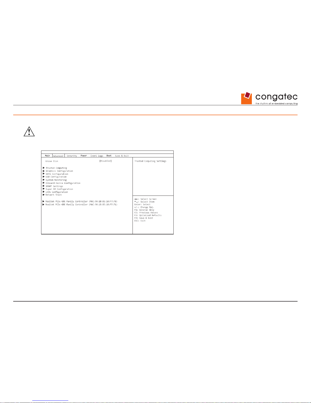
Copyright © 2014 congatec AG IGX1m02 72/134
17 Advanced Menu – Advanced system
conguration
The advanced functions which are available to the system are congured in this
menu for the advanced system conguration.
Only change the default settings if required for a special purpose.
Incorrect settings can cause malfunctions.
Advanced Menu – Advanced system
configuration
Example showing the Advanced menu
Page 73
Copyright © 2014 congatec AG IGX1m02 73/134
17.1 TPM (Trusted Platform Module) Computing
Opens the submenu for enabling TPM and changing the TPM settings. If this setup
menu is available, the system board contains a security
and encryption chip (TPM - Trusted Platform Module) which complies with TCG specication 1.2. This chip allows security-related data
(passwords, etc.) to be stored securely. The use of TPM is standardized
and is specied by the Trusted Computing Group (TCG).
17.1.1 TPM Support
Species whether the TPM (Trusted Platform Module) hardware is available. If the TPM is
disabled, the system behaves like any other
system without TPM hardw are.
Disabled
Trusted Platform Module is not available.
Enabled
Trusted Platform Module is available.
17.1.2 TPM State
Species whether TPM (Trusted Platform Module) can be used by the operating system.
Disabled
Trusted Platform Module cannot be used.
Enabled
Trusted Platform Module can be used.
17.1.3 Pending TPM operation
Species a TPM operation which will be performed during the next boot process.
None
No TPM operation will be performed.
Enable Take
Ownership The operating system can assume ownership of the TPM.
Disable Take Ownership The op erating system c annot assume ownership o f the TPM.
TPM Clear
TPM is reset to the factory setting. All keys in the TPM will be deleted.
Page 74
Copyright © 2014 congatec AG IGX1m02 74/134
17.1.4 Current TPM Status Information
Shows the current TPM (Trusted Platform Module) status.
• TPM SUPPORT OFF Is display ed if the TPM Support is disabled.
• TPM
Enabled Status Indicates whether TPM can be used.
• TPM Active Status Indicates whether TPM is enabled.
• TPM Owner Status Indicates the TPM owner status.
17.2 SATA Conguration
Opens the SATA conguration submenu.
17.2.1 SATA Mode
Species in which mode the SATA ports will be operated.
IDE
The SATA port is operated in IDE Mode.
AHCI
The SATA port is operated in AHCI Mode.
RAID (if available)
The SATA port is operated in RAID Mode.
17.2.2 mSATA Support
Determines whether mSATA modules are detected automatically.
Auto
If the mSATA module has an mSATA Present Pin, the module is detected automatically.
Enabled
The mSATA interface is always active.
Page 75
Copyright © 2014 congatec AG IGX1m02 75/134
17.3 Graphics Conguration
Opens the submenu for conguring the graphics controller on the system board.
17.3.1 Primary Display
Species the image source during the Power On Self Test (POST).
Auto
If the display adapter is inserted, this is used as the image source during the POST. Otherwise, the graphics device
(IGD) integrated in the system board is used.
IGD
The Integrated Graphics Device (IGD) on the system board serves as the only image source during the POST.
PEG
If the PCI Express display adapter is inserted, this is used as the image source during the POST. Otherwise the IGD is used.
17.3.2 Internal Graphics
Use this option if you wish to use a PCI or PEG card as the primary image source and the graphics controller on the system board (IGD-Integrated
Graphics Device) as the secondary image source.
Disabled
If it is not used as the rst image source, the IGD is disabled and is not available
to the operating system.
Enabled
If the IGD is not used as the primary image source, it can be used for operation with several monitors after the POST.
17.3.3 IGD Memory
Congures the size of the main memory used for the graphics controller on the
system board (Integrated Graphics Drive-IGD).
32M...1024M
The set value species the size of the shared memory available to the integrated
graphics in megabytes.
17.4 LVDS Conguration
Opens the submenu to congure the LVDS interface for direct connection of an LCD panel.
Page 76
Copyright © 2014 congatec AG IGX1m02 76/134
17.4.1 LVDS Support
Determines whether the LVD S interface is available.
Disabled
The LVDS interfac e is not available.
Enabled
The LVDS interface is available.
17.4.2 LVDS Panel Cong Select
Determines the resolution of the LVDS (Low Voltage Differential Signalling) interface. The selected resolution should be the same as that of
the connected LCD panel.
By using the “LVDS” OEM tool, an additional LVDS adjusted parameters entry can be
created, which enables the use of freely congurable
LVDS parameters.
17.4.3 Non-EDID Support
For LCD panels that do not support a DDC (Display Data Channel), no EDID
(Extended Display Identication Data) is available.
For LCD panels without EDID support, Enabled must be set. To install a Linux operating system, it may be necessary to initially select “NonEDID Support = Disabled”, despite having a connected LVDS panel without DDC support. After the Linux and driver installation is completed,
“Non-EDID Support = Enabled” can be set again.
Disabled
The LCD provides EDID.
Enabled
The LCD does not provide EDID.
17.4.4 LVDS Mode
The selected mode of the LV DS interface must be supported by the LCD panel used.
Page 77
Copyright © 2014 congatec AG IGX1m02 77/134
Faulty color display often indicates an incorrectly congured LVDS mode.
FPDI 8 bit
FPDI (Flat Panel Interface) 8 bit mode is being used.
FPDI 6 bit
FPDI (Flat Panel Interface) 6 bit mode is being used.
LDI 8 bit
LDI (LVDS Display Interface) 8 bit mode is being used.
LDI 6 bit
LDI (LVDS Display Interface) 6 bit mode is being used.
17.4.5 LVDS Channel Swap
Depending on the connected LCD panel, the channels of the LVDS interface can be swapped.
Disabled
The channels of the LVDS interface are not swapped .
Enabled
The channels of the LVDS interface are swapped.
17.4.6 LVDS Backlight-Enable Polarity
Depending on the connected LCD panel, the polarity for enabling backlighting can be set.
Active High
The polarity for enabling backlighting of the LCD panel is Active High.
Active Low
The polarity for enabling backlighting of the LCD panel is Active Low.
17.4.7 LVDS Brightness Control
Determines whether the brightness of the LCD panel connected at the LVDS interface
is controlled in the BIOS setup or under the operating
system.
OS Controlled
The brightness of the LCD panel connected at the LVDS interface is controlled under the operating system.
BIOS Controlled
The brightness of the LCD panel connected at the LVDS interface is controlled in
the BIOS setup.
Page 78
Copyright © 2014 congatec AG IGX1m02 78/134
17.4.8 LVDS Brightness
Determines the brightness of the LCD panel connected at the LVDS interface. Permissible values: 0..255
0 stands for the minimum (0 V) and 255 for the maximum (4V) brightness voltage level at the corresponding inverter connection.
17.4.9 POST Screen Mode
Determines whether the output during POST is in graphic mode or text mode.
To view outputs during POST, text mode must be selected for LCD panels with a resolution < 800x600.
Graphic Mode
The system is in graphic mode during POST and BIOS setup.
Text Mode
The system is in text mode during POST and BIOS setup.
17.5 USB Conguration
17.5.1 USB Devices
Shows the number of available USB devices, USB keyboards, USB mice and USB hubs.
17.5.2 Legacy USB Support
Species whether legacy USB support is available. This function should always be enabled or
set to Auto so that the operating system can
be booted from a USB device if required.
Disabled
Legacy USB support is not available. A USB keyboard or USB mouse can only be used if this is supported by the
operating system. Booting the operating system from a USB device is not possible.
Enabled
Legacy USB support is available. A USB keyboard or USB mouse can also be used if the operating system does not
Page 79
Copyright © 2014 congatec AG IGX1m02 79/134
support USB. Booting the operating system from a USB device is possible.
Auto
Legacy USB support will be disabled if no USB devices are connected.
Legacy USB support should be disabled if the operating system supports USB and you do not want to boot the operating system from USB
devices.
17.5.3 USB Transfer Time-Out
If USB devices are not detected during the POST, it is possible to increase the waiting time so that slower USB devices can also be
detected.
1..5..20 sec
Waiting time setting for USB devices in seconds.
17.5.4 Mass Storage Devices
List of USB Mass Storage Device(s)
Allows the user to force a particular device emulation. When set to Auto, the devices
are emulated according to their media format. Optical
drives are emulated as “CD ROM”
and drives without data media according to the drive type.
Auto
Emulation is chosen depending on the USB device.
Floppy
Force USB oppy emulation.
Hard Disk
Force USB hard disk emulation.
CD-ROM
Force USB CD ROM emulation.
17.6 USB Port Security
Opens the USB Port Security submenu in order to congure the USB interfaces present on the conga-IGX.
Page 80
Copyright © 2014 congatec AG IGX1m02 80/134
17.6.1 USB Port Control
Congures the use of the USB ports. Disabled USB ports are only available during the
POST, but are no longer available under the
operating system.
Enable all ports
All USB ports are enabled.
Enable front and
internal ports All USB ports on the rear of the device are disabled.
Enable rear and
internal ports All USB ports on the front of the device are disabled.
Enable internal
ports only All external USB ports are disabled.
17.6.2 USB Device Control
For the Enable front and internal ports, Enable rear and internal ports and Enable used p orts settings, which were made under USB Port Control,
there are additional options available here.
Enable all devices Those settings made under USB Port Control will be used without any limitation.
Enable Keyboard
and Mouse only Only USB keyboards and USB mice can be operated at the USB ports enabled under USB Port
Control. Any ports to which no USB keybo ards or USB mice are connected are disabled. Keyboards with an
integrated hub result in deactivation of the port.
Enable all devices
except mass storage devices/Hubs USB ports on which USB storage devices or USB hubs are connected will be
disabled.
17.7 System Monitoring
17.7.1 Controller Revision
Shows the version of the system monitoring controller.
17.7.2 Firmware Version
Shows the rmware version of the system monitoring controller.
Page 81
Copyright © 2014 congatec AG IGX1m02 81/134
17.7.3 Chassis Type
Displays the current chassis type.
17.7.4 TCV Version
Shows the TCV version (Tem perature Characteristics Values).
17.7.5 Fan Control
Species whether the fan speed will be adjusted automatically.
Enabled
The fan speed is adjusted automatically.
Disabled
The fan speed is not adjusted automatically. All fans are operated at maximum speed.
Page 82
Copyright © 2014 congatec AG IGX1m02 82/134
17.7.6 Fan2 Wiring
Determines whether a three-wire or four-wire fan is connected to fan conn ector Fan2.
3 wires
A three-wire fan is connected.
4 wires
A four-wire fan is connected.
17.8 Onboard Device Conguration
Opens the submenu to congure devices on the system board. Some of them
are only available under certain conditions.
17.8.1 Audio Conguration
Azalia HD Audio
Allows the onboard Azalia HD (High Denition) audio controller to be enabled.
Disabled The onboard audio controller is disabled.
Enabled The onboard audio controller is enabled.
Front Panel Audio
Makes it possible to use a legacy front audio connector (AC97). The automatic check of
whether an audio connection is occupied is not
supported with this setting.
High denition
For the use of a high denition audio cable with automatic occupancy
recognition.
Legacy
For the use of a legacy audio cable without automatic occupancy recognition.
17.8.2 High Precision Event Timer Conguration
High Precision Timer
Provided that it is enabled, the operating system is able to make use of the High Precision
Event Timer, which allows it to meet the
requirements of time-critical applications. The advanced timer is also known as the Multimedia Timer.
Page 83
Copyright © 2014 congatec AG IGX1m02 83/134
Disabled The High Precision Event Timer is disabled.
Enabled The High Precision Event Timer is enabled.
17.8.3 LAN 1
Species whether the LAN 1 controller is available.
Disabled The LAN 1 controller is not available.
Enabled The LAN 1 controller is available.
17.8.4 LAN 2
Species whether the LAN 2 controller is available.
Disabled The LAN 2 controller is not available.
Enabled The LAN 2 controller is available.
17.9 Super IO Conguration
17.9.1 Super IO Chip
Shows information about the Super IO Chip.
17.10 Serial Port 0 Conguration
Opens the submenu to congure the serial port 0 (COMA).
17.10.1 Serial Port
Species whether the serial port is available.
Page 84
Copyright © 2014 congatec AG IGX1m02 84/134
Disabled The serial port is not available.
Enabled The serial port is available.
17.10.2 Device Settings
Shows the base I/O address and the interrupt used for access to the parallel port.
17.10.3 Change Settings
Species which base I/O addresses and which interrupts can be used by the BIOS
or operating system for the particular serial port.
Auto
The base I/O address and the interrupt are automatically
assigned.
IO=3F8h; IRQ=4;
The base I/O address 3F8h and the interrupt 4 are
permanently assigned.
IO=3F8h; IRQ=3,4,5,6,7,9,10,11,12;
The base I/O address is permanently assigned.
IO=2F8h; IRQ=3,4,5,6,7,9,10,1 1,12;
IO=3E8h; IRQ=3,4,5,6,7,9,10,1 1,12;
IO=2E8h; IRQ=3,4,5,6,7,9,10,1 1,12;
The values given in the list are available for the interrupt for automatic selection
by the BIOS or the operating system.
If conicts with other devices occur, this option should be converted to Auto.
17.11 Serial Port 1 Conguration
Opens the submenu for conguration of the serial port 1 (COMB).
Page 85
Copyright © 2014 congatec AG IGX1m02 85/134
17.11.1 Serial Port
Species whether the serial port is available.
Disabled The serial port is not available.
Enabled The serial port is available.
17.11.2 Device Settings
Shows the base I/O address and the interrupt used for access to the parallel port.
17.11.3 Change Settings
Species which base I/O addresses and which interrupts can be used by the BIOS
or operating system for the particular serial port.
Auto
The base I/O address and the interrupt are automatically
assigned.
IO=2F8h; IRQ=3;
The basic I/O address 2F8h and the Interrupt 3 are rmly
allocated.
IO=3F8h; IRQ=3,4,5,6,7,9,10,11,12;
The base I/O address is permanently assigned.
IO=2F8h; IRQ=3,4,5,6,7,9,10,11,12;
IO=3E8h; IRQ=3,4,5,6,7,9,10,11,12;
IO=2E8h; IRQ=3,4,5,6,7,9,10,11,12;
The values given in the list are available for the interrupt for automatic selection
by the BIOS or the operating system.
If conicts with other devices occur, this option should be converted to Auto.
17.12 Parallel Port Conguration
Opens the submenu to congure the parallel port (LPT).
Page 86
Copyright © 2014 congatec AG IGX1m02 86/134
17.12.1 Parallel Port
Species whether the parallel port is available.
Disabled The parallel port is not available.
Enabled The parallel port is available.
17.12.2 Device Settings
Shows the base I/O address and the interrupt used for access to the parallel port.
17.12.3 Change Settings
Species which base I/O addresses and which interrupts can be used by the BIOS
or operating system for the particular serial port.
Auto
The base I/O address and the interrupt are automatically
assigned.
IO=378h; IRQ=5;
The basic I/O address 2F8h and the Interrupt 3 are rmly
allocated.
IO=378h; IRQ=5,6,7,9,10,11,12;
The base I/O address is permanently assigned.
IO=278h; IRQ=5,6,7,9,10,11,12;
IO=3BCh; IRQ=5,6,7,9,10,11,12;
The values given in the list are available for the interrupt for automatic selection
by the BIOS or the operating system.
If conicts with other devices occur, this option should be converted to Auto.
17.12.4 Device Mode
Species whether the parallel port should be used as an input/output port or just as an output
port. The ECP and EPP transfer modes permit
higher transfer speeds of 2 or 2.4 Mbyte/sec. These modes can however only be used on devices that also support these modes. In addition,
for EPP the I/O address of the parallel port must be set to 378 h or 278 h.
Page 87
Copyright © 2014 congatec AG IGX1m02 87/134
Standard Parallel Port Mode The standard mode will be used for the parallel port.
EPP Mode
Fast transfer mode (up to 2 MByte/sec), data output and data reception are possible. The mode requires a
peripheral device which supports the EPP (Enhanced Parallel Port) mode.
ECP Mode
Fast transfer mode (up to 2.4 MByte/sec), data output and data reception are possible. The mode requires a
peripheral device which supports the ECP (Extended Capability Port) mode. The necessary DMA channel is
determined by the system.
EPP Mode & ECP
Mode Both transfer modes are available.
17.13 Network Stack
Species whether the UEFI Network Stack is available for network access under UEFI. If the
UEFI Network Stack is disabled, UEFI installation
via PXE is not possible, for example.
Disabled
The UEFI Network Stack is not available.
Enabled
The UEFI Network Stack is available.
17.13.1 Ipv4 PXE Support
Species whether PXE UEFI Boot via Ipv4 is available for installation of
operating systems in UEFI mode.
Disabled PXE UEFI Boot via Ipv4 is not available.
Enabled PXE UEFI Boot via Ipv4 is available.
17.13.2 Ipv6 PXE Support
Species whether PXE UEFI Boot via Ipv6 is available for installation of
operating systems in UEFI mode.
Disabled PXE UEFI Boot via Ipv6 is not available.
Enabled PXE UEFI Boot via Ipv6 is available.
Page 88
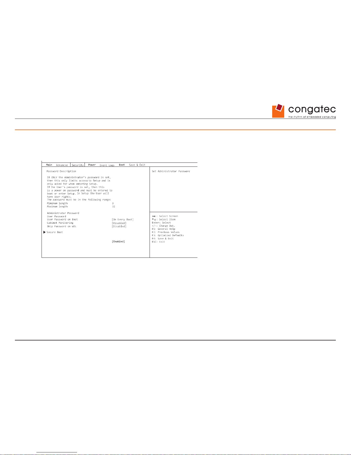
Copyright © 2014 congatec AG IGX1m02 88/134
18 Security Menu – Security Functions
The Security menu offers various options for protecting your system and personal data from un authorized access. Using a sensible
combination of these options will help you achieve maximum protection for your system.
The following security settings can be made in this menu. Some of them are
only available under certain conditions.
18.1 Password Description
Neither an Administrator password nor a User password has been allocated.
Opening the BIOS Setup and booting the system are possible without restriction.
Only the Administrator password was allocated.
If ONLY an Administrator password was allocated, only the BIOS Setup is protected. Booting
the system can be performed without restriction.
When you access the BIOS Setup with an Administrator password, the Administrator access level is assigned to you and you have unrestricted
access to the BIOS Setup. If you access the BIOS Setup without a password, access to the BIOS Setup is limited because you are only
assigned the User access level.
Page 89
Copyright © 2014 congatec AG IGX1m02 89/134
Administrator AND user passwords were allocated.
If administrator and user passwords were allocated, the authorisation level in the BIOS Setup
depends on the password entered. If you access
the BIOS Setup with the administrator password, unlimited access to the BIOS Setup is possible, entry of the user password results in limited
access. Booting the system is possible both with the administrator and also with the user password.
If the administrator password is deleted, the user password will also be deleted.
The system will stop after an incorrect password has been entered three times. If this happens, switch off the system and then back on again,
and enter the correct password.
18.2 Administrator Password
If you press the enter key, a window will open in which you can assign the Administrator
password. Enter a character string to dene the
password. If you conrm an empty password eld, the password will be deleted.
To call up the complete BIOS Setup, you need the administrator level of
access. If an Administrator password is allocated, the user
password only
allows very limited access to the BIOS Setup.
18.3 User Password
If you press the enter key, a window will open in which you can assign the User password. Enter a character string to dene the password.
With the User password, you can prevent unauthorized access to your system.
In order to be able to assign a User password, an Administrator password must already have been assigned.
Page 90
Copyright © 2014 congatec AG IGX1m02 90/134
18.4 User Password on Boot
Species whether a user password must be entered before the boot process.
On Every Boot
Entry of a user password is required before every boot process.
Disabled
The system starts without requiring the entry of a user password.
If the administrator password and the user password have been assigned and the
setting Disabled has been chosen for this item, simply press
Enter to get USER access
to the BIOS Setup. In this case the user password does not have to be entered.
18.5 Cabinet Monitoring
Species whether opening of the casing should be monitored.
Disabled
The system continues to operate normally even if the casing has been opened.
Enabled
If the casing has been opened, then the boot process is suspended until the BIOS Setup is called. If the BIOS Setup is
protected with a password, then this
must be entered. An SMBIOS event log entry will be generated.
18.6 Skip Password on WOL
Species whether a user password will be skipped or must be entered during
a system boot via Wake on LAN.
Disabled The user password must be entered via using the keyboard during the system boot.
Enabled
The user password is deactivated during the system boot with Wake On LAN.
18.7 FLASH Write
Supplies the system BIOS with write protection.
Disabled
The system BIOS cannot be written. A ash BIOS update is not possible
Enabled
The system BIOS can be written. A ash BIOS update is possible.
Page 91
Copyright © 2014 congatec AG IGX1m02 91/134
18.8 Secure Boot
Opens the submenu for conguring Secure Boot.
18.8.1 Platform Mode
Shows whether the system is in user mode or setup mode.
User
In user mode, the Platform Key (PK) is installed. Secure Boot can be enabled or disabled via the Secure Boot Control menu
option.
Setup
In setup mode, the Platform Key (PK) is not installed. Secure Boot is disabled and cannot be enabled via the Secure Boot
Control menu option.
18.8.2 Secure Boot
Indicates whether the Secure Boot function is active.
Disabled
Secure Boot is not active.
Enabled
Secure Boot is active.
18.8.3 Secure Boot Control
Species whether booting of unsigned boot loaders/UEFI OpROMs is permitted.
The associated signatures are saved in the BIOS or can be reloaded
in the Key Management submenu.
Disabled
All boot loaders / OpROMs (Legacy / UEFI) can be executed.
Enabled
Only booting of signed boot loaders/UEFI OpROMs is permitted.
Page 92
Copyright © 2014 congatec AG IGX1m02 92/134
18.8.4 Secure Boot Mode
Species whether the Key Management submenu is available.
Default The Key Management submenu is not available.
Custom
The Key Management submenu is available.
18.8.5 Key Management
Submenu for deleting, changing and adding the key and signature databases required for Secure Boot.
Without the installed Platform Key (PK), the system is in setup mode (Secure Boot is disabled). As soon as the PK is installed, the system
switches t o user mode (Secure Boot can be enabled).
Factory Default Key Provisioning
If the system is in setup mode (no Public Key is installed), it is possible to install
the default Secure Boot key and signature databases.
Disabled
The available Secure Boot key and signature databases remain unchanged.
Enabled
If the PK, KEK, DB, DBX signature databases are not available, the default Secure Boot key and signature databases will
be installed after rebooting the system.
Delete All Secure Boot Variables
Puts the system in setup mode (Secure Boot is disabled). All keys and signature
databases (PK, KEK, DB, DBX) in the system are deleted.
Install All Factory Default Keys
All keys and signature databases (PK, KEK, DB, DBX) in the system are reset to the default
values. This menu option is only available when
the PK is deleted.
Save Secure Boot Keys
Saves the Secure Boot Key and Key Databases to the selected drive.
Page 93
Copyright © 2014 congatec AG IGX1m02 93/134
Platform Key (PK)
Shows the current status of the Platform Key (PK).
Installed
The PK is installed. System is in user mode.
Not Instal
led
The PK is not installed. The system is in setup mo de.
Set new PK
Sets the Platform Key (PK). After selecting the drive, the corresponding le
must be selected in the browser.
Delete PK
Deletes the Platform Key (PK), which puts the system in setup mode and disables Secure Boot.
Key Exchange Key Database (KEK)
Shows the current status of the Key Exchange Key Database (KEK).
Installed The KEK Database is installed.
Not installed The KEK Database is not installed.
Set new KEK
Sets the Key Exchange Key Database (KEK) After selecting the drive, the
corresponding le must be selected in the browser.
Delete KEK
Deletes the Key Exchange Key Database (KEK)
Append Var to KEK
Adds an entry to the Key Exchange Key Database (KEK). After selecting the drive,
the corresponding le must be selected in the browser.
Page 94
Copyright © 2014 congatec AG IGX1m02 94/134
Authorized Signature Database (DB)
Shows the current status of the Authorized Signature Database (DB).
Installed The DB is installed.
Not installed The DB is not installed.
Set new DB
Sets the Authorized Signature Database (DB). After selecting the drive, the
corresponding le must be selected in the browser.
Delete DB
Deletes the Authorized Signature Database (DB).
Append Var to DB
Adds an entry to the Authorized Signature Database (DB). After selecting the drive, the corresponding le must be selected in the browser.
Forbidden Signature Database (DBX)
Shows the current status of the Forbidden Signature Database (DB).
Installed The DBX is installed.
Not installed The DBX is not installed.
Set new DBX
Sets the Forbidden Signature Database (DB). After selecting the drive, the
corresponding le must be selected in the browser.
Delete DBX
Deletes the Forbidden Signature Database (DB).
Append Var to DBX
Adds an entry to the Forbidden Signature Database (DBX). After selecting the drive,
the corresponding le must be selected in the browser.
Page 95
Copyright © 2014 congatec AG IGX1m02 95/134
18.9 HDD Security Conguration
18.9.1 HDD Password on Boot
Species whether a hard disk user password must be entered during every boot process.
Disabled It is not necessary to enter a hard disk user password during the boot process.
Enabled
Entry of a hard disk user password is required during every boot process.
18.10 HDD n / HDD-ID
Opens a submenu with information about the hard disk user password.
18.10.1 HDD Password Description
Allows the hard disk user and master passwords to be set, changed and deleted. The hard disk user password must be set up before the
Enabled Security setting can be carried out. The hard disk master password can only be changed if you have successfu lly unlocked it in
POST with the hard disk master password.
18.10.2 HDD Password Conguration
Shows the current security status of the hard disk.
18.10.3 Security Supported
Yes is shown here if the device supports use of a hard disk user password. In this case it is possible to assign a pass word to the hard
drive.
18.10.4 Security Enabled
Ye s is shown here if either a hard d isk user password or a hard disk master password has been assigned to the hard disk.
Page 96
Copyright © 2014 congatec AG IGX1m02 96/134
18.10.5 Security Locked
The hard disk is locked if it was not unlocked with the valid password.
18.10.6 Security Frozen
If Yes is displayed, then a hard disk user password cannot be set up, changed or deleted. To change the security frozen status to No, the
system must have been shut down before the BIOS Setup is called. Only then can a hard disk user password be set up, changed or deleted.
18.10.7 HDD User Password Status
Shows whether a hard disk user password was allocated or not.
18.10.8 HDD Master Password Status
Shows whether a hard disk master password was allocated or not.
18.10.9 Set User Password
The hard disk user password protects the hard disk(s) from unauthorized access. Booting the operating system from the hard disk or accessing
the data on the hard disk can only be carried out by those people who know the hard disk user password. The hard disk user password can
be up to 32 characters long. The settings become effective immediately and also remain so, regardless of
how you later end the BIOS Setup.
The hard disk user password is requested during the POST.
If you press the Enter key, a window will open in which you can assign the
hard disk user password. Enter a character string to dene the
password. If you
conrm an empty password eld, the password will be deleted.
18.10.10 Set Master Password
If a hard disk user password has been forgotten, it can be deleted using the hard disk master password. This option is only available if an
incorrect hard disk user password has been entered three times when the system is booting during POST. The hard disk master password for
your hard disk can be obtained from the hard disk vendor but only if the particular HDD-ID is provided together with a valid proof of purchase.
Page 97
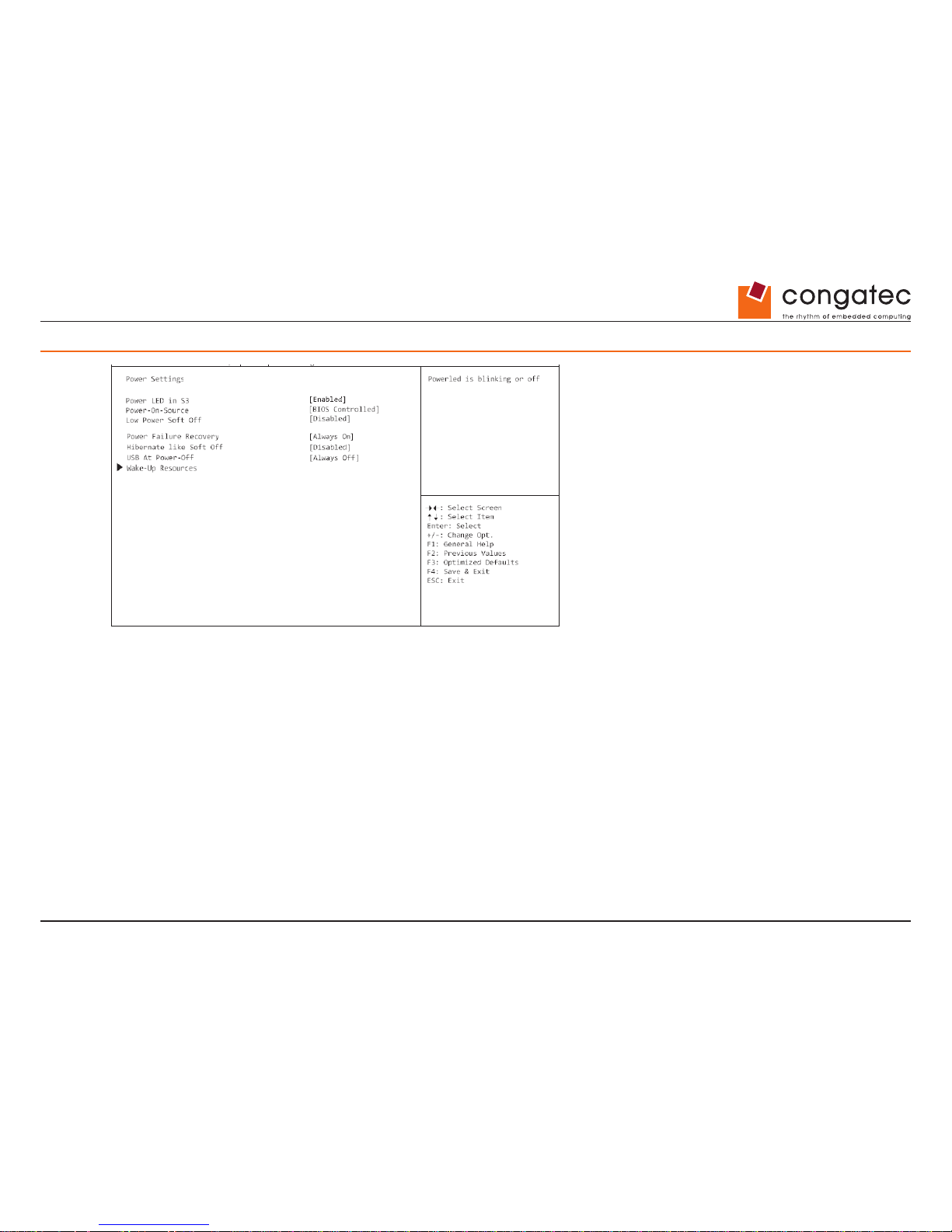
Copyright © 2014 congatec AG IGX1m02 97/134
19 Power Menu – Energy saving functions
Example showing the Power menu.
19.1 Power Settings
19.1.1 Power LED in S3
Determines the behaviour of the Power LED in standby (S3).
Disabled The Power LED is disabled in standby.
Enabled
The Power LED ashes in standby.
Page 98
Copyright © 2014 congatec AG IGX1m02 98/134
19.1.2 Power On Source
Species whether the switch-on sources for the system are managed via BIOS
or via an ACPI operating system.
BIOS Controlled
The switch-on sources are managed via BIOS.
ACPI Controlled
The switch-on sources are managed via the ACPI operating system.
19.1.3 Low Power Soft Off
Reduces the energy consumption of a system that is switched off.
When Low Power Soft Off is enabled, the system can only be switched on with
the power button on the casing. The device cannot be
switched on using the power button of a USB keyboard or a Wake-on-LAN signal.
Disabled
Low Power Soft Off is disabled.
Enabled
Low Power Soft Off is enabled.
19.1.4 Power Failure Recovery
Species how the system behaves during a reboot following a power failure.
Always Off
The system switches on briey, performs a status check (initialisation), and then switches off.
Always On The system switches on.
Previous State
The system switches on briey, performs a status check, and then returns the mode it was in before the power failure
occurred (ON or OFF).
Disabled The system does not switch on.
Page 99
Copyright © 2014 congatec AG IGX1m02 99/134
19.1.5 Hibernate like Soft Off
In order to also reduce the energy consumption in hibernate mode (S4), the system will instead
be brought into Low Power Soft Off or Zero
Watt mode (S5) when it is switched of f. However, the
energy consumption will only reduce if Low Power Soft Off or Zero Watt mode is enabled.
Disabled
The system will be brought into hibernate mode (S4).
Enabled
Instead of going into hibernate mode (S4), the system will be brought into Low Power
Soft Off or Zero Watt mode (S5).
19.1.6 USB At Power Off
Enables/disables the power supply for the USB ports. This option is only available if
Low Power Soft Off and Zero Watt mode are disabled.
Always off
The USB ports are no longer supplied with power after the system is shut down.
Always on
The USB ports continue to be supplied with power after the system is shut down.
19.2 Wake-Up Resources
This submenu is only available if neither Zero-Watt mode nor Low Power Soft Off i s enabled.
19.2.1 LAN
Determines whether the system can be switched on via a LAN controller (on the system board or expansion card).
Enabled The system can be switched on via a LAN controller.
Disabled The system cannot be switched on via a LAN controller.
Page 100
Copyright © 2014 congatec AG IGX1m02 100/134
19.2.2 Wake On LAN Boot
Species the system behavior when switched on by means of network signals.
Boot
Sequence
After being switched on via the LAN, the system boots up according to the device
sequence specied in the boot
menu.
Force LAN Boot After being switched on via the LAN, the system is booted remotely via the LAN.
19.2.3 Wake Up Timer
The time at which the system should be switched on can be specied here.
Disabled Wake Up Timer is not enabled.
Enabled
Wake Up Timer is enabled. The system is switched on at the time specied.
19.2.4 Hour
Species the hour of the switch-on time.
19.2.5 Minute
Species the minute of the switch-on time.
19.2.6 Second
Species the second of the switch-on time.
19.2.7 Wake Up Mode
Species whether the system should be switched on daily, on selected week days
or only once a month at the specied time.
Daily
The system will be switched on daily at the time specied.
Weekly
The system is switched on at the specied time on the selected week days.
 Loading...