

Confer Plastics CCX-IG, CCX-IG System Assembly, Installation And Use Manual
To reduce the risk of drowning, entrapment, falls, paralysis, electrocution, or other
serious injury or death:
Dealer/Installer: Give manual to homeowner.
Installer: Read "Safe Installation" on p. 2 and all instructions before beginning. For proper assembly and installation,
instructions must be followed completely.
Homeowner: Read "Safe Use" on back cover before using. Save these instructions.
MODEL CCX-IG
CURVE STEP / CURVE STEP SYSTEM
ASSEMBLY, INSTALLATION AND USE MANUAL
STEP TO BE INSTALLED ON INSIDE OF POOL ONLY
WEIGHT LIMIT 400 LBS.
Assembly video available online: www.conferplastics.com
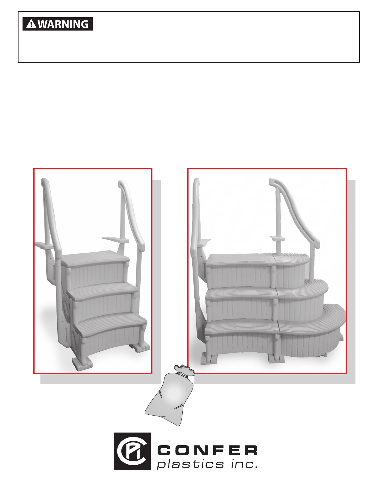
Model CCX-IG
Curve Step
Note: 40 lbs. of sand required!
SAND
Model CCX-IG System
Curve Step System
Note: 70 lbs. of sand required!
Made in the USA
U.S. patent 8,936,134

Model# CCX-IG - CURVE IN-GROUND POOL STEP ASSEMBLY INSTRUCTIONS
Safe Installation
To reduce the risk of electrocution, drowning, entrapment, falls, or other serious injury or
death:
Check building codes/permitting. Consult your local Building Department before installation of your pool and equipment.
Pool/equipment installation must comply with the codes of the authority having jurisdiction and may require permits (e.g.,
building, plumbing, electrical, zoning, etc.).
Use for intended purpose only
• Use only as swimming pool stairs.
• These steps are designed and manufactured for a specic pool wall height and/or deck of the pool - check product
specication and the height of your pool.
Check that you have all required parts. Check the contents of the carton with the Parts list for this step system. All parts
and hardware are required. If any parts are missing, DO NOT attempt to assemble or install the steps. Instead, call Toll
Free U.S. - 800-635-3213 or visit our web site at www.conferladders.com for assistance.
Select an appropriate location - The step system must be located on a solid base.
Follow all instructions
• For stable, correct assembly and installation, all instructions must be followed completely and in the sequence shown.
• Follow the manufacturer’s recommendations for the safe use of all hand tools and equipment used during installation.
Cordless drill only - no corded drills near pool. Use a cordless drill for assembly and installation. To reduce the risk of
electrocution, NEVER use a corded drill in or around a pool.
Lift safely. When lifting awkward or heavy loads, have another person help you.
Double check after installation
• Before using the product, after assembly and installation, go over the instructions and procedures again to make sure
nothing has been overlooked.
• Make sure that safety labels are installed and legible.
Parts List
2 - Side panels [part A]
4 - Plugs [installed in parts A]
1 - Panel brace [part B]
3 - Curved risers [part C]
4 - Handrail posts [part E]
2 - Deck connectors [part F]
2 - Handrails [part G]
4 - Foot pads [part H]
2 - Treads [part I]
1 - Top tread [part I-3]
Assembly Video
Available online at
www.conferplastics.com
Hardware Pack
10 - #10 x 1-1/4” screws
2 - Labels-No Jumping/
Diving (pre-installed)
Needed for Assembly:
- Second person to assist
- Rubber mallet
- Funnel
- Cordless Drill
- 1/8” drill bit
- Phillips screwdriver
- Liquid soap or lubricant
- Sand - 40 lbs. for (Curve Step)
- 70 lbs. for (Curve System)
Scale size photo of screw
USE A LITTLE
LIQUID SOAP ON
TABS TO HELP
WITH ASSEMBLY
Hardware not provided to fasten step to concrete. Purchase locally.
G
I-3
I
C
H
A
B
F
E
Confer Plastics “CURVE” In-Ground Pool Step must be assembled with the treads and risers curved inward
The CURVE Step requires 40 lbs. of sand to complete assembly. The Curve Step with optional add-on requires a total of
70 lbs. of sand. Choose a location close to the swimming pool for assembly. If you have a pool deck it is recommended
to build the step on top of the deck to avoid lifting completed step over the pool wall.
Step 1
Stand up both side
panels [A]. Insert panel
brace [B] with vent hole
up into opening located
on [A] then push down
to lock in place.
2
Step 2
With the thin edge of the
curved riser [C] facing
downward align the lower
tabs with the openings on
part [A] and push in.
Note risers must be
curved inward.
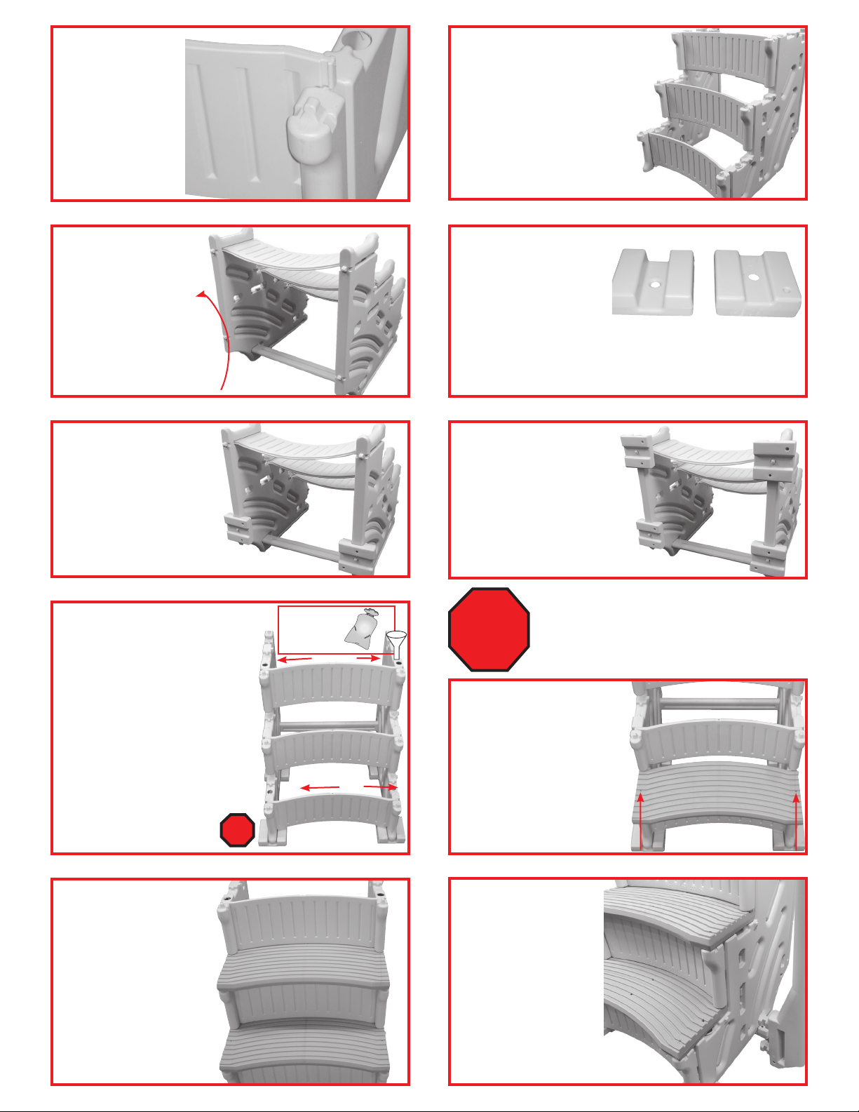
Step 3
While holding lower
tabs in part [A] align
the top tabs then tap
down with a rubber
mallet until flush.
Step 4
Install the rest of the curved
risers [C] by flexing the side
panels [A] outward enough
to insert part [C] tabs into
part [A]. Tap into place with
rubber mallet.
Step 5
Tilt the step
backwards to expose
all four of the rounded
tabs on the bottom
edges. Apply a little
liquid soap on the
[4] tabs to help with
installing foot pads.
Rotate
90°
Step 7
The two back foot pads [H]
will always be installed with
#1 facing up. Place part [H]
over the rounded tab, strike
with a rubber mallet until
seated onto the rounded
tab. Repeat to install
second part [H].
Step 9
Each side panel [A] requires 20
lbs of sand split between the two
fill holes. Sand is needed as ballast
to hold step down in the water.
Remove the caps installed in the
panels then using a funnel fill the
lower hole completely to the top
with sand. Shake the panel to help
settle the sand, lower hole must
be completely filled. Pour what’s
left from the 20 lbs into the upper
fill hole. Using provided caps, plug
both the lower and upper fill
holes. Repeat procedure to
fill the second part [A].
STOP!
Pour
sand into
funnel.
SAN D
Step 6
Installing the Foot Pads
[H]: If swimming pool has
a flat bottom, all four foot
pads [H] will be installed
with the #1 facing up. If swimming pool has a slight taper
towards the center, the back foot pads will be installed
with #1 facing up and the front foot pads with #2 facing up.
#1
#2
Step 8
Determine which side will
be facing up on the front
foot pads [H], # 1 for a flat
bottom pool or # 2 for
a pool with slight taper
towards thecenter, install
both parts [H].
IF YOU HAVE THE CONFER CURVE STEP
AND DO NOT HAVE THE ADD-ON
CONTINUE WITH STEPS 10-18.
STOP!
IF YOU HAVE THE CONFER CURVE STEP
WITH THE OPTIONAL ADD-ON SKIP STEPS
11-18 AND GO TO STEP 19.
Step 10
Install the first tread [I] by
placing over the tabs on
the side panels as shown.
While holding part [I]
down on the side panels
tap inward with a rubber
mallet until locked in
place.
Step 11
Repeat step 10 to install
second tread [I].
Step 12
To install the lower
handrail posts [E] first
locate the openings on
part [A] just below the
second tread marked
with #3. Next insert the
tabs on part [E] all the
way into the openings
then tap down with a
rubber mallet until seated. Repeat to install the
other part [E].
3
 Loading...