

Page 1
To reduce the risk of drowning, entrapment, falls, paralysis, electrocution, or other
serious injury or death:
Dealer/Installer: Give manual to homeowner.
Installer: Read "Safe Installation" on p. 2 and all instructions before beginning. For proper assembly and installation,
instructions must be followed completely.
Homeowner: Read "Safe Use" on back cover before using. Save these instructions.
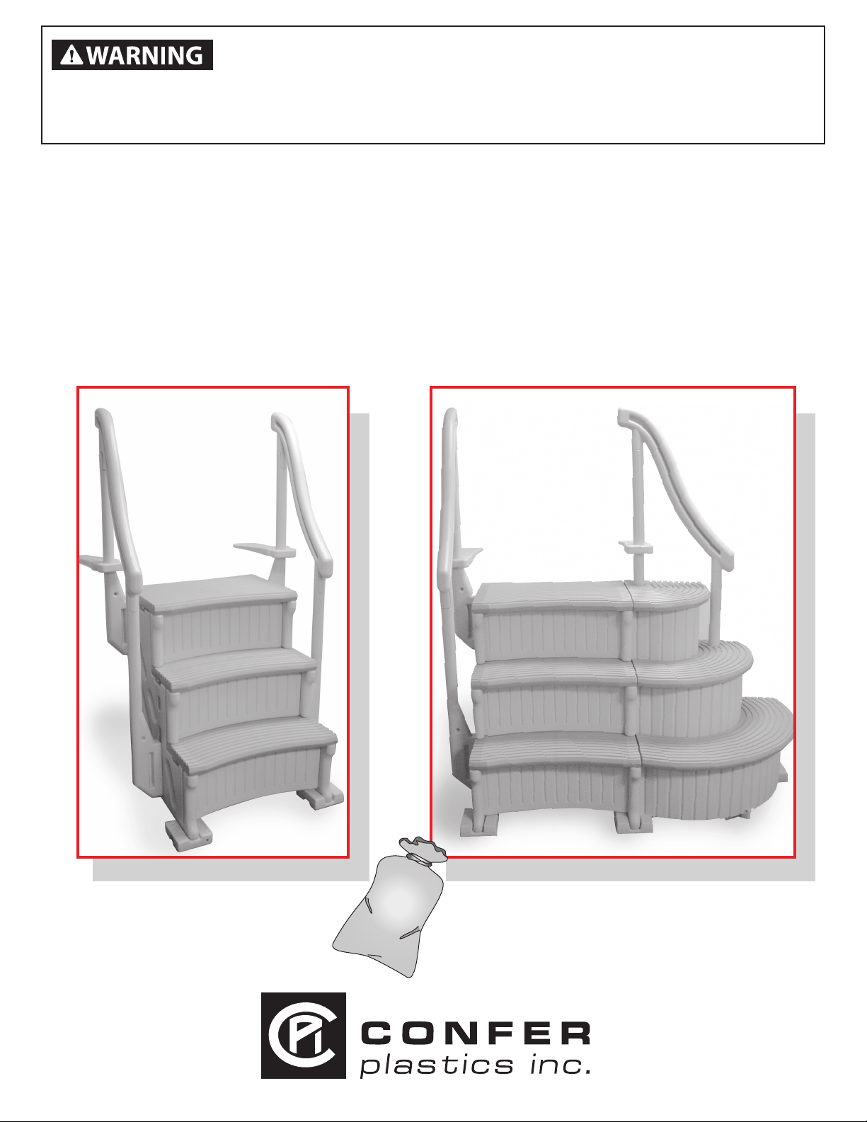
MODEL CCX-IG
CURVE STEP / CURVE STEP SYSTEM
ASSEMBLY, INSTALLATION AND USE MANUAL
STEP TO BE INSTALLED ON INSIDE OF POOL ONLY
WEIGHT LIMIT 400 LBS.
Assembly video available online: www.conferplastics.com
Model CCX-IG
Curve Step
Note: 40 lbs. of sand required!
SAND
Model CCX-IG System
Curve Step System
Note: 70 lbs. of sand required!
Made in the USA
U.S. patent 8,936,134
Page 2
Model# CCX-IG - CURVE IN-GROUND POOL STEP ASSEMBLY INSTRUCTIONS
Safe Installation
To reduce the risk of electrocution, drowning, entrapment, falls, or other serious injury or
death:
Check building codes/permitting. Consult your local Building Department before installation of your pool and equipment.
Pool/equipment installation must comply with the codes of the authority having jurisdiction and may require permits (e.g.,
building, plumbing, electrical, zoning, etc.).
Use for intended purpose only
• Use only as swimming pool stairs.
• These steps are designed and manufactured for a specic pool wall height and/or deck of the pool - check product
specication and the height of your pool.
Check that you have all required parts. Check the contents of the carton with the Parts list for this step system. All parts
and hardware are required. If any parts are missing, DO NOT attempt to assemble or install the steps. Instead, call Toll
Free U.S. - 800-635-3213 or visit our web site at www.conferladders.com for assistance.
Select an appropriate location - The step system must be located on a solid base.
Follow all instructions
• For stable, correct assembly and installation, all instructions must be followed completely and in the sequence shown.
• Follow the manufacturer’s recommendations for the safe use of all hand tools and equipment used during installation.
Cordless drill only - no corded drills near pool. Use a cordless drill for assembly and installation. To reduce the risk of
electrocution, NEVER use a corded drill in or around a pool.
Lift safely. When lifting awkward or heavy loads, have another person help you.
Double check after installation
• Before using the product, after assembly and installation, go over the instructions and procedures again to make sure
nothing has been overlooked.
• Make sure that safety labels are installed and legible.
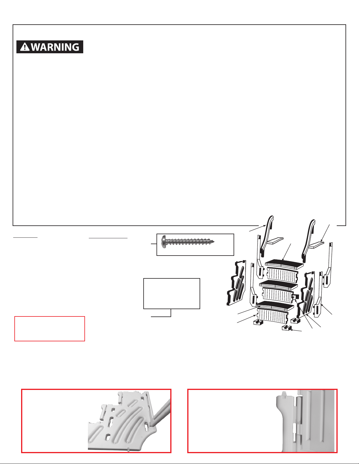
Parts List
2 - Side panels [part A]
4 - Plugs [installed in parts A]
1 - Panel brace [part B]
3 - Curved risers [part C]
4 - Handrail posts [part E]
2 - Deck connectors [part F]
2 - Handrails [part G]
4 - Foot pads [part H]
2 - Treads [part I]
1 - Top tread [part I-3]
Assembly Video
Available online at
www.conferplastics.com
Hardware Pack
10 - #10 x 1-1/4” screws
2 - Labels-No Jumping/
Diving (pre-installed)
Needed for Assembly:
- Second person to assist
- Rubber mallet
- Funnel
- Cordless Drill
- 1/8” drill bit
- Phillips screwdriver
- Liquid soap or lubricant
- Sand - 40 lbs. for (Curve Step)
- 70 lbs. for (Curve System)
Scale size photo of screw
USE A LITTLE
LIQUID SOAP ON
TABS TO HELP
WITH ASSEMBLY
Hardware not provided to fasten step to concrete. Purchase locally.
G
I-3
I
C
H
A
B
F
E
Confer Plastics “CURVE” In-Ground Pool Step must be assembled with the treads and risers curved inward
The CURVE Step requires 40 lbs. of sand to complete assembly. The Curve Step with optional add-on requires a total of
70 lbs. of sand. Choose a location close to the swimming pool for assembly. If you have a pool deck it is recommended
to build the step on top of the deck to avoid lifting completed step over the pool wall.
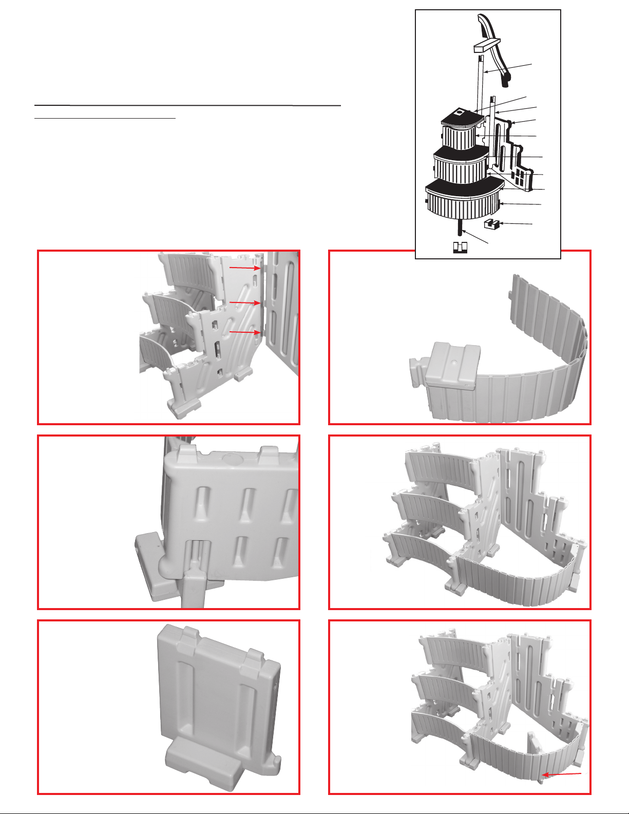
Step 1
Stand up both side
panels [A]. Insert panel
brace [B] with vent hole
up into opening located
on [A] then push down
to lock in place.
2
Step 2
With the thin edge of the
curved riser [C] facing
downward align the lower
tabs with the openings on
part [A] and push in.
Note risers must be
curved inward.
Page 3
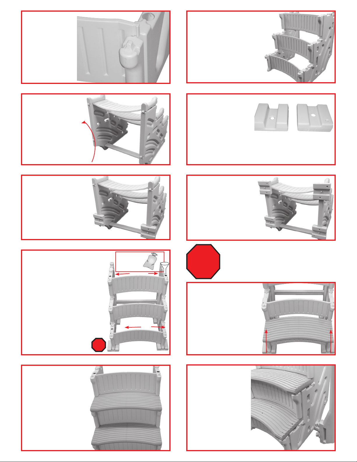
Step 3
While holding lower
tabs in part [A] align
the top tabs then tap
down with a rubber
mallet until flush.
Step 4
Install the rest of the curved
risers [C] by flexing the side
panels [A] outward enough
to insert part [C] tabs into
part [A]. Tap into place with
rubber mallet.
Step 5
Tilt the step
backwards to expose
all four of the rounded
tabs on the bottom
edges. Apply a little
liquid soap on the
[4] tabs to help with
installing foot pads.
Rotate
90°
Step 7
The two back foot pads [H]
will always be installed with
#1 facing up. Place part [H]
over the rounded tab, strike
with a rubber mallet until
seated onto the rounded
tab. Repeat to install
second part [H].
Step 9
Each side panel [A] requires 20
lbs of sand split between the two
fill holes. Sand is needed as ballast
to hold step down in the water.
Remove the caps installed in the
panels then using a funnel fill the
lower hole completely to the top
with sand. Shake the panel to help
settle the sand, lower hole must
be completely filled. Pour what’s
left from the 20 lbs into the upper
fill hole. Using provided caps, plug
both the lower and upper fill
holes. Repeat procedure to
fill the second part [A].
STOP!
Pour
sand into
funnel.
SAN D
Step 6
Installing the Foot Pads
[H]: If swimming pool has
a flat bottom, all four foot
pads [H] will be installed
with the #1 facing up. If swimming pool has a slight taper
towards the center, the back foot pads will be installed
with #1 facing up and the front foot pads with #2 facing up.
#1
#2
Step 8
Determine which side will
be facing up on the front
foot pads [H], # 1 for a flat
bottom pool or # 2 for
a pool with slight taper
towards thecenter, install
both parts [H].
IF YOU HAVE THE CONFER CURVE STEP
AND DO NOT HAVE THE ADD-ON
CONTINUE WITH STEPS 10-18.
STOP!
IF YOU HAVE THE CONFER CURVE STEP
WITH THE OPTIONAL ADD-ON SKIP STEPS
11-18 AND GO TO STEP 19.
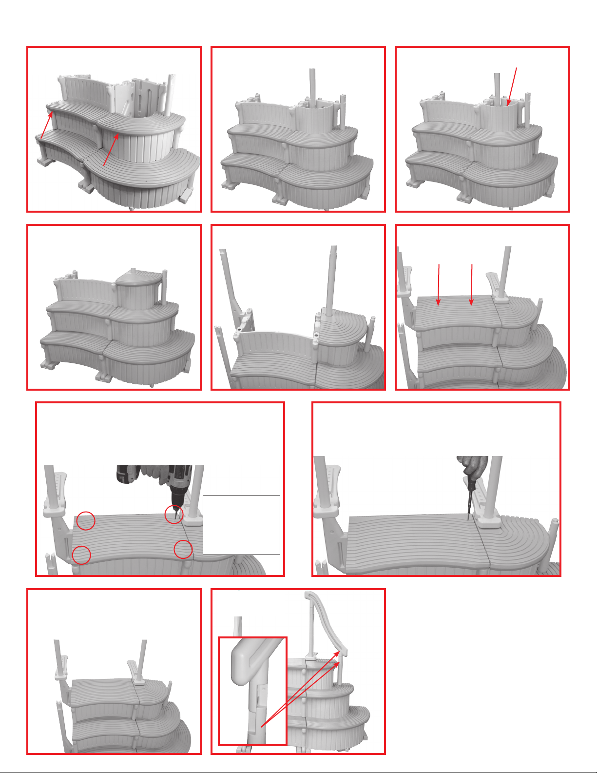
Step 10
Install the first tread [I] by
placing over the tabs on
the side panels as shown.
While holding part [I]
down on the side panels
tap inward with a rubber
mallet until locked in
place.
Step 11
Repeat step 10 to install
second tread [I].
Step 12
To install the lower
handrail posts [E] first
locate the openings on
part [A] just below the
second tread marked
with #3. Next insert the
tabs on part [E] all the
way into the openings
then tap down with a
rubber mallet until seated. Repeat to install the
other part [E].
3
Page 4
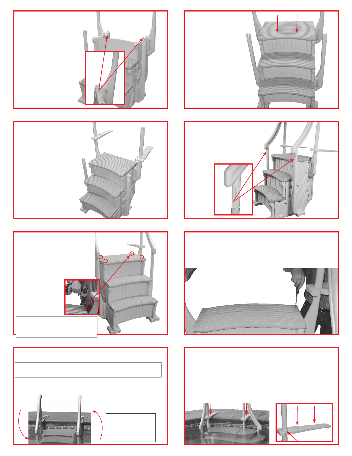
Step 13
To install the upper
handrail posts [E] first
locate the openings
on panel [A] marked
with #3. Next insert
the tabs on part [E] all
the way into the openings then tap down
with a rubber mallet
until seated. Repeat
to install the other
part [E].
Step 14
The top tread [I-3] will
install slightly different than the previous
two. Install this tread
by placing over the
four tabs located on
side panels [A]. Using
a rubber mallet strike
the top of the tread
directly over the tabs
until seated.
Step 15
Place one of the
deck connectors
[F] over the upper
handrail post and
slide down. Check
to make sure side
marked [This Side
down] is
facing downward.
Repeat to install the
second part [F]
Step 16 (Cont.)
With your Curve step fully
assembled locate the [4]
recessed screw locations on
the top tread. With a cordless
drill, at each of these [4]
locations drill a
small 1/8” pilot
hole completely
through the tread
and into the
sidewall below.
Step 16
Place handrails [G]
over the top of handrail posts, push down
to lock in place.
Step 16 (Cont.)
Using a Phillips head screwdriver install one of the
#10 x 1-1/4” stainless screws at each location [4 total].
[HAND TIGHTEN ONLY]
WARNING!
Using a corded drill near pool
may result in electrocution.
Step 17
With a helper place the pool step into
swimming pool.
WARNING! Pool step will be heavy. Have additional
help. Do not attempt to place the step by yourself.
Hold the step under water at a slight angle until all the air
bubbles stop. Tilt the step in the other direction until all the
air bubbles stop. Be patient this process will take a few
minutes. If the pool step is still floating all of the air is not
out. Lean step to the side again until air bubbles stop.
WARNING!
DO NOT LIFT
THE STEP BY
HANDRAILS!
4
Step 18
of step must not touch pool liner] extend the two deck con-
nectors onto the pool deck and attach to the handrail posts
using 2- #10 x 1-1/4” screws through the deck connectors
and into the posts. If you have a wood deck attach the deck
connectors to the pool deck using 2-#10 x 1-1/4 screws in
each connector. If your pool deck is concrete consult with
your local hardware store for the proper anchors and screws.
With the step in place and positioned about
1 inch away from inside of pool wall [back
Page 5
CONFER CURVE STEP
ADD-ON INSTRUCTIONS
The curve add-on can only be installed on the right side
of the step as you are facing it. The add-on requires
an additional 30 lbs. of sand.
Additional Parts for Step Add-On
2 - Foot pads [Part H]
1 - Add-on panel [Part J]
1 - Short hand rail post [Part K]
1 - Long hand rail post [Part L]
1 - Large flex riser [Part M]
1 - Tread support [Part N]
1 - Large curved tread [Part O]
*PARTS “T” AND “U” NOT USED WITH CCX-IG STEPS.
PLEASE [DISCARD/RECYCLE]
USE A LITTLE LIQUID SOAP ON TABS TO HELP WITH ASSEMBLY
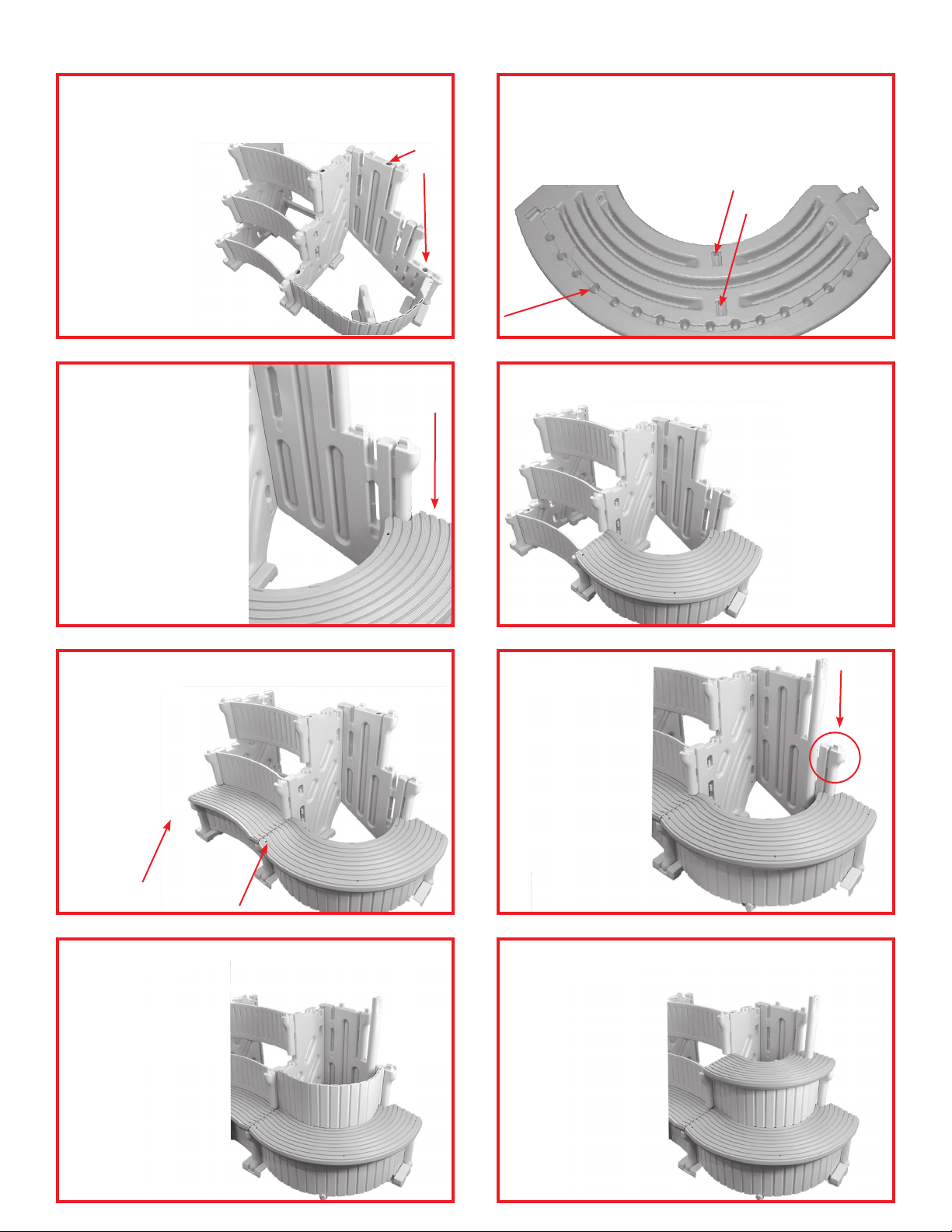
Step 19
Install the add-on
panel [J] by inserting
the three tabs into the
three openings located
towards the back
of step panel [A].
Push the tabs all
the way in,
then tap panel
down with a
rubber mallet
until seated
in openings.
1 - Medium flex riser [Part P]
1 - Medium curved tread [Part Q]
1 - Small flex riser [Part R]
1 - Small curved tread [Part S]
2 - Plugs [WG] (installed in add-on panel)
1 - Tread filler [Part T]
1 - Tread extension [Part U]
L
S
K
J
R
Q
P
O
M
H
N
Step 20
Next, install one of the foot pads [H]
onto the tab located on the bottom of
the large flex riser [M] by placing over
the raised tab and striking with a rubber mallet until seated. Foot pad [H]
should be installed in the same
direction as the
front foot pads
on base step.
[Refer to steps
7 & 8].
Step 21
Tilt the step back
far enough to slide
the end of large flex
riser [M] up into the
slot located on the
front bottom edge
of the add-on side
panel.
Step 23
Attach the last foot
pad [H] on to the
bottom of the tread
support [N] by placing over the raised
tab and striking
with a rubber mallet
until seated. Foot
pad [H] should be
installed in the same
position as the front
foot pads on base
step.
Step 22
Insert the
tab on the
other end of
the flex riser
[M] into the
opening on
side panel
[A].
Step 24
Locate the notch
on the bottom
edge of the
large flex riser
[M]. Slide the
step support
[N] under then
rotate up making
sure part is in
notch.
5
Page 6
CONFER CURVE STEP ADD-ON INSTRUCTIONS (Cont’d.)
At this time add 30 lbs of sand through
Step 25
completely to the top with sand. Shake the panel
to help settle
the sand. Lower
hole must be
completely filled.
Using the provided
caps plug both the
lower and upper
fill hole.
the two fill holes located on the add-on
panel. Using a funnel fill the lower hole
Step 27
It will be easier to start from
the add-on panel side and
work towards the base step.
Start by placing the large
curved tread in approximate
position over the panels and
flex riser. Next align the tabs
on the add-on panel with the
openings on the bottom side
of large curved tread. Lock
the tread down by striking
top of tread directly over the
tabs with rubber mallet.
Fill
Holes
Step 26
The next step will require an extra set of hands to help
align the large flex riser [M] and the tread support [N]
into the groove and the openings located on the bottom
side of the large curved tread [O].
Step 28
Position the other end of the tread over
side panel [A]. Move the large flex riser [M]
in or out until it slips up into the groove
located on the bottom of
the large curved tread [O].
It will also be necessary
to align the tabs on the
tread support [N] with
the two openings on
the bottom of the large
curved tread.
Once everything
is in position tap
down on the large
tread to lock onto
panel [A].
Step 29
panels [A] as shown.
While holding the
tread down, tap
inward with a
rubber mallet until
locked in place.
Step 31
Insert the tab located
on the end of flex
riser into the opening
on side panel [A].
Riser will rest on
the top back of
tread below.
Install the first tread [I] onto the base
step by placing over the tabs on the
side
Next, install the medium flex riser [P]
by sliding down into the slot located
on the add-on panel [J].
Step 30
Install the short
handrail post [K]
into the lower
opening on the
add-on panel
[J] marked with
#3 next to it.
Push the tab on
the post all the
way in; then tap
down to lock in
place.
Step 32
panel [J].
Move the riser in or
out until it slips up
into the groove on
the bottom of the
tread, using a
rubber mallet strike
the top of the tread
until locked
onto tabs.
Place the medium curved tread [Q]
over the short handrail post and down
on to the tabs located on the add-on
6
Page 7
CONFER CURVE STEP ADD-ON INSTRUCTIONS (Cont’d.)
Install the second tread
Step 33
Step 36
rail post and attach the same as in step 32.
[I] onto the base step
Place the small curved
tread [S] over the hand-
Install the long hand-
Step 34
panel [J] marked with #3 next to it. Push
the tab all the way in then tap down to
lock in place.
Step 37
to the left side panel by
repeating steps 12
and 13.
rail post [L] into the
opening on the add-on
Install the lower and
upper handrail posts [E]
Step 35
Step 38
Install the small flex
riser [R]
Repeat step 14 to
install the top tread
[1-3].
Step 38 (Cont.)
With your Curve step fully assembled locate the [4]
recessed screw locations on the top tread. At each of
these locations [4 total] drill a 1/8” pilot hole completely
through the tread and into the step sidewall below.
WARNING!
Using a corded
drill near pool
may result in
electrocution.
Step 39
upper handrail posts and slide down.
Check to make sure the side marked [this
side down] is facing downward.
Place both deck
connectors [F] over the
Step 40
Step 38 (Cont.)
Using a Phillips head screwdriver install one of the
#10 x 1-1/4” stainless screws at each location [4 total].
[HAND TIGHTEN ONLY]
Place handrails [G]
over the top of handrail
posts and push down
to lock in place.
TO COMPLETE STEP AND
PLACE IN POOL FOLLOW
STEPS 17 THROUGH 18 ON
PAGE 4 OF THE INSTRUCTIONS.
NO ADDITIONAL SCREWS
NEEDED FOR ADD-ON
CURVED TREADS.
7
Page 8
Safe Use
To reduce the risk of drowning, entrapment, falls,
paralysis, or other serious injury or death:
Use step system properly.
• No diving or jumping from steps - shallow water; risk of paralysis or death.
• ONE PERSON ON THE LADDER/STAIR AT A TIME.
Weight limit - 400 lbs maximum. Exceeding maximum weight may cause the
stairs to fail.
Secure stairs when not in use. When pool is not in use, make sure gate is
closed and locked.
Watch children at all times when they are in or around water to help prevent drowning.
BE SURE AND SAFE. The manufacturer IS NOT responsible for improper
WEEKLY STEP MAINTENANCE -
To prevent algae growth it’s important
to have properly balanced pool water.
Consult with your pool professional
for proper choice of pool sanitizer. In
addition, at least once a week, while
inside swimming pool, use a garden
hose with a good high pressure nozzle
to spray under and behind the step
system. The force of the water will
flush out any dirt, allowing the pool
filter to remove it from the water.
assembly Installation and use.
WINTERIZING / REMOVING STEP FROM POOL
PLAN AHEAD - PEOPLE WILL HAVE TO GET IN THE POOL TO MOVE OR REMOVE THE STEP.
When winterizing your pool, if you decide to leave the pool step in the pool be sure to detach the step from the pool deck
and move the step towards the center of the pool and away from the pool wall. Remove any outside steps or ladders from
the pool area to eliminate access to the pool.
If you decide to remove your pool step from the pool:
Pool step will be heavy and must be lifted from within the pool. Have additional help if you
move the step or choose to remove it from swimming pool. Do not attempt to do this by
yourself - 2-3 people are required to move pool step safely. DO NOT lift pool step by handrails or handrail posts - they
may detach, possibly resulting in a fall.
Remove any outside steps or ladders from the pool area to eliminate access to the pool.
To remove the step start by disconnecting both of the mounting brackets from the deck. From inside the pool position one
person on each side of the step, grip the bottom of the side panels and carefully lift the step high enough to start tilting
back on the pool deck. DO NOT LIFT STEP BY HANDRAILS, POSTS OR TOP TREAD. THE HANDRAILS, POSTS AND
TOP TREAD WILL NOT SUPPORT THE WEIGHT OF THE POOL STEP AND MAY DETACH OR BREAK, RESULTING IN A
FALL OR INJURY.
With most of the weight off the step, continue lifting and tilting back on to deck. Leave the step lying on it back edges for
a couple of hours to drain the water. Once the water is drained stand the step up.
With the water drained your Confer step can be stored outside during the off season, it is not necessary to store inside.
CONFER PLASTICS INC. FIVE YEAR WARRANTY
Confer Plastics Inc. warrants their swimming pool ladders and steps to be free from defects in
workmanship for five years from date of purchase.
DO NOT RETURN DEFECTIVE PART TO DEALER
E-MAIL CONFER PLASTICS AT: [email protected]
A PICTURE [S] OF DEFECTIVE PART, A BRIEF DESCRIPTION OF PROBLEM,
PROOF OF PURCHASE AND YOUR CONTACT INFORMATION.
INFORMATION MAY ALSO BE FAXED TO CONFER PLASTICS AT: 716-694-3102
OR MAILED TO THE ADDRESS BELOW. UPON REVIEW OF THE INFORMATION YOU
WILL BE NOTIFIED IF PART IS COVERED UNDER THE WARRANTY AND
THE SHIPPING/HANDLING CHARGES.
This warranty gives you specific legal rights, and you may also have other rights which may vary from state to state.
Confer Plastics Inc.
97 Witmer Road
North Tonawanda, N.Y. 14120-2421
MADE IN THE USA
8
Printed in USA
97 Witmer Road
North Tonawanda, New York 14120-2421
Toll Free U.S. 800-635-3213
FAX 716-694-3102
www.conferladders.com
CP-CURVE STEP-IG REV. 1-19
 Loading...