

Confer Plastics CCX-AG, CCX-AG System Assembly And Installation Manual
SAVE THESE INSTRUCTIONS
SAND
DEALER/INSTALLER: GIVE TO HOMEOWNER
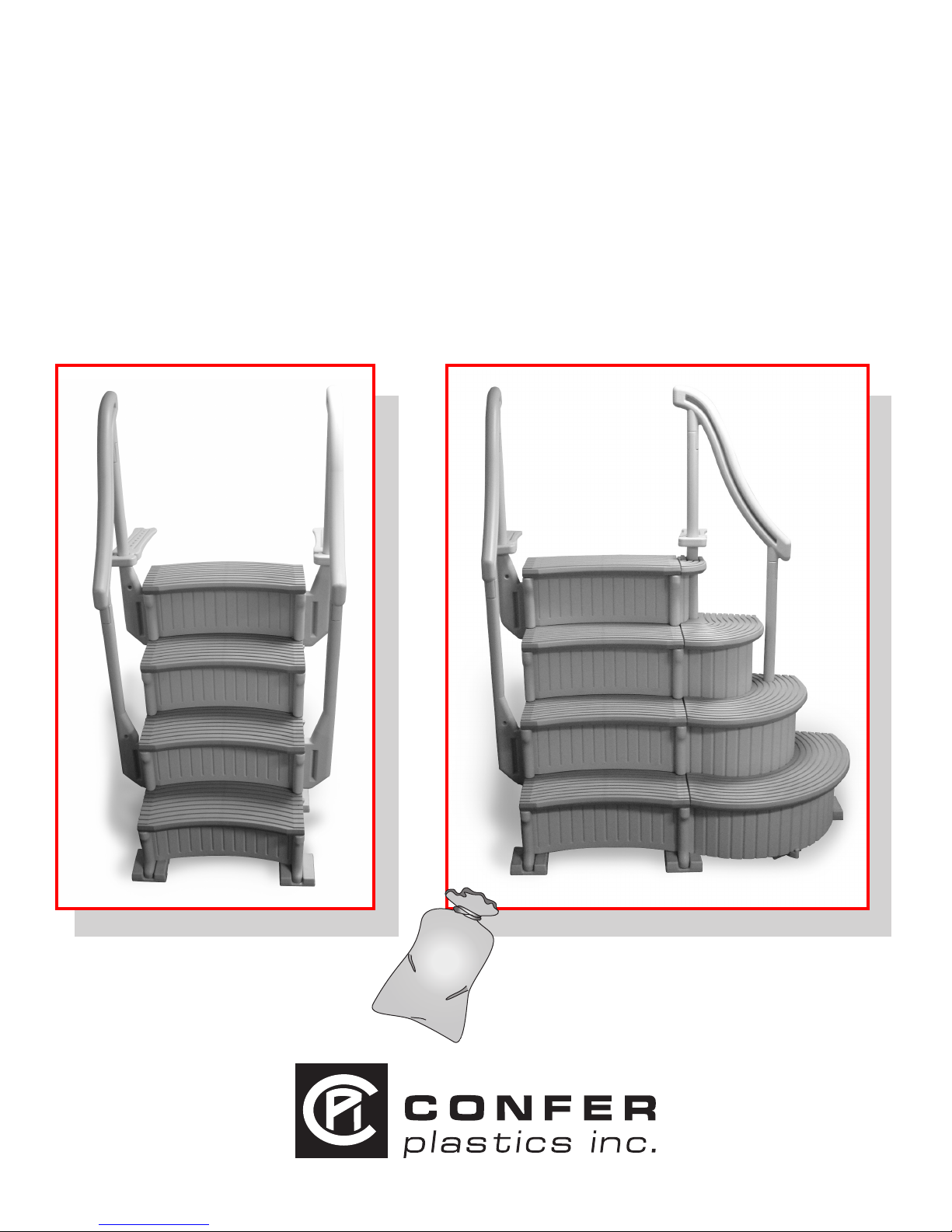
CONFER ABOVE GROUND
CURVE STEP / ABOVE GROUND
CURVE STEP SYSTEM
ASSEMBLY AND INSTALLATION MANUAL
Model CCX-AG
Note: 40 lbs. of sand required!
Model CCX-AG System
Note: 70 lbs. of sand required!
Made in the U.S.A. by
www.conferladders.com
Model# CCX-AG - CURVE ABOVE GROUND POOL STEP
ASSEMBLY INSTRUCTIONS - PLEASE READ BEFORE ATTEMPTING ASSEMBLY
F
Parts List
2 - Side panels [part A]
1 - Panel brace [part B]
4 - Curved risers [part C]
2 - Panel extensions [part D]
4 - Handrail posts [part E]
2 - Deck connectors [part F]
2 - Handrails [part G]
4 - Foot pads [part H]
4 - Treads [part I]
Hardware Pack
4 - Plugs (wg)
8 - #10 x 1-1/4" screws
2 - Labels-No Jumping/Diving
G
D
Needed for Assembly
- Rubber mallet
- Funnel
- Cordless Drill
- Phillips screwdriver
- Liquid soap or lubricant
- Sand - 40 lbs. for (Curve Step)
- 70 lbs. for (Curve System)
E
I
C
H
B
A
If missing parts call - Toll free U.S. - 800-635-3213 or www.Conferplastics.com
Confer Plastics “CURVE” Above Ground Pool Step can be assembled with the treads curved inward or curved
outward. Determine which direction you want the steps before starting assembly.
The CURVE Step requires 40 lbs. of sand to complete assembly. The Curve Step with optional add-on requires a
total of 70 lbs. of sand. Choose a location close to the swimming pool for assembly. If you have a pool deck it is
recommended to build the step on top of the deck to avoid lifting completed step over the pool wall.
Step 1
Stand up both side
panels [A]. Insert
panel brace [B] into
opening located on
[A] then push down
to lock in place.
Step 2
Attach one of the
panel extensions [D]
to part [A] by sliding
in from the side until
flush. Repeat to
attach the second
part [D].
Step 3
With the thin edge
of the curved riser
[C] facing downward align the
lower tabs with the
openings on part
[A] and push in.
2
Step 4
While holding lower
tabs in part [A] align
the top tabs then
tap down with a
rubber mallet until
flush.
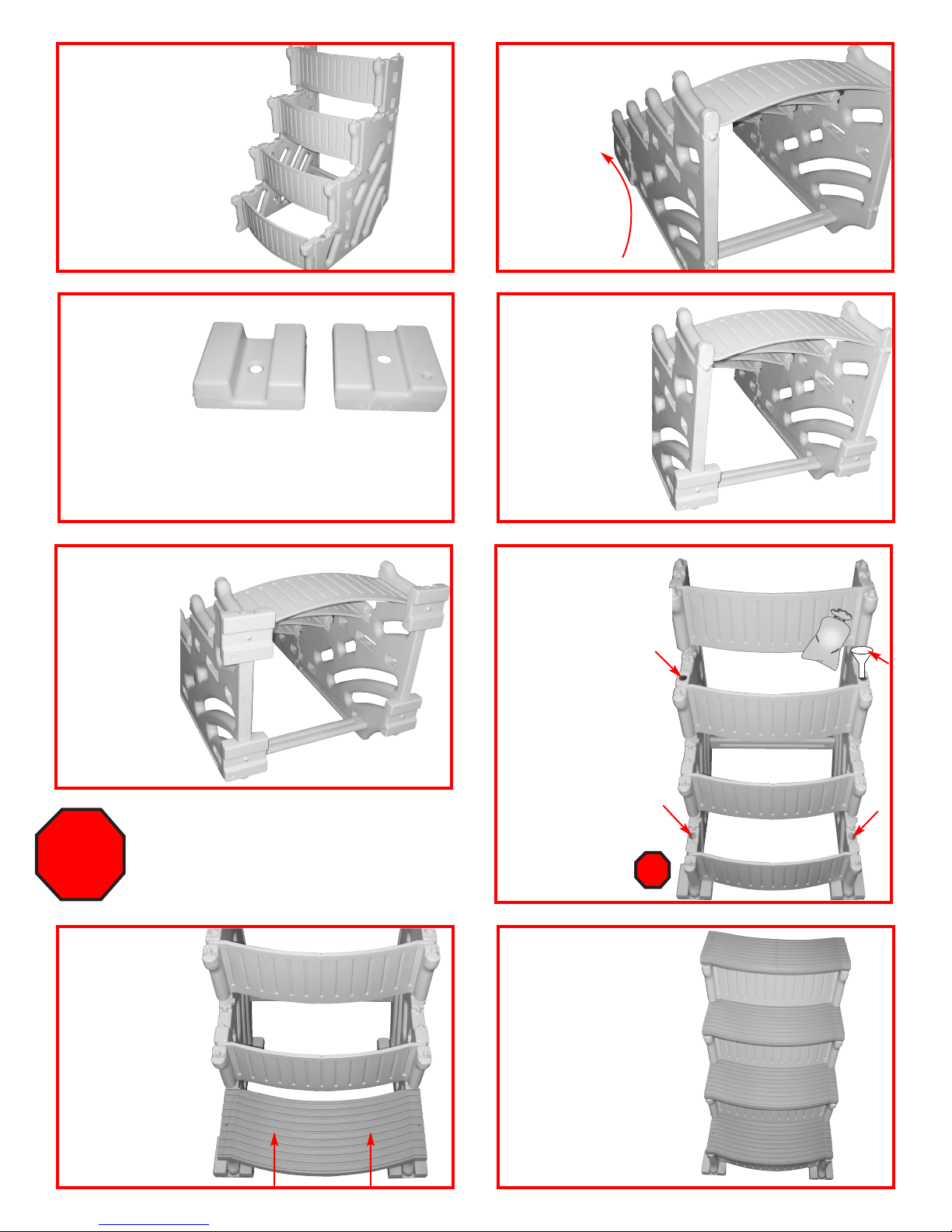
Step 5
SAND
Install the rest of
the curved risers
[C] by flexing the
side panels [A]
outward enough to
insert part [C] tabs
into part [A]. Tap
into place with
rubber mallet.
Step 6
Tilt the step
backwards to
expose all four
of the rounded
tabs on the
bottom edges.
Rotate
90°
Step 7
Installing the
Foot Pads [H]:
If swimming
pool has a flat
bottom, all four
foot pads [H] will be installed with the #1 facing up.
If swimming pool has a slight taper towards the
center, the back foot pads will be installed with #1
facing up and the front foot pads with #2 facing up.
#1
Step 9
Determine which
side will be facing
up on the front
foot pads [H],
# 1 for a flat
bottom pool or
# 2 for a pool
with slight taper
towards the
center, install
both parts [H].
IF YOU HAVE THE CONFER CURVE STEP
WITHOUT THE ADD-ON CONTINUE WITH
STEP 11.
STOP!
IF YOU HAVE THE CONFER CURVE STEP
WITH OPTIONAL ADD-ON SKIP STEPS 11-18
AND CONTINUE WITH STEP 19.
#2
Step 8
The two back foot
pads [H] will always
be installed with #1
facing up. Place part
[H] over the rounded
tab, strike with a
rubber mallet until
seated onto the
rounded tab. Repeat
to install second
part [H].
Step 10
Each side panel [A]
requires 20 lbs of sand
split between the two fill
holes. Sand is needed
as ballast to hold step
down in the water. Using
a funnel fill the lower hole
completely to the top with
sand. Shake the panel to
help settle the sand, lower
hole must be completely
filled. Pour whatʼs left from
the 20 lbs into the upper
fill hole. Using provided
cap, plug the lower fill hole
only. Upper fill hole must
remain open. Repeat
procedure to fill the
second part [A].
STOP!
Pour
Pour
sand into
sand into
funnel.
funnel.
Step 11
Install the first
tread [I] by placing
over the tabs on
the side panels as
shown. While
holding part [I]
down on the side
panels tap inward
with a rubber
mallet until locked
in place.
Step 12
Repeat to install the second
and third treads [I]. The fourth
[Top] tread [I] will install slightly
different than the previous
three. Install this tread by
placing over the four tabs
located on the panel extensions [D]. Using a rubber
mallet strike the top of the
tread directly over the tabs
until seated. All treads and
risers must be installed in
the same direction.
3
 Loading...