

Page 1
To reduce the risk of drowning, entrapment, falls, paralysis, electrocution, or
other serious injury or death:
Dealer/Installer: Give manual to homeowner.
Installer: Read "Safe Installation" on page #2 and all instructions before beginning. For proper assembly and
installation, instructions must be followed completely.
Homeowner: Read "Safe Use" on back cover before using. Save these instructions.
Installation must comply with local codes and may require permits.
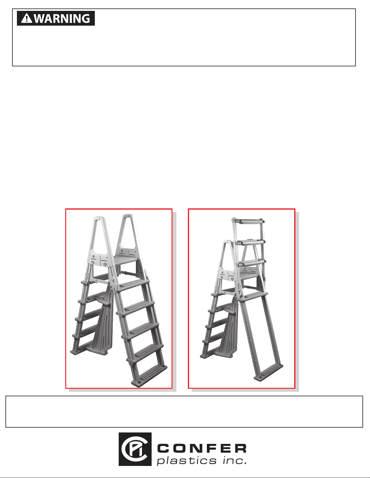
MODEL #7000X
ELIMINATOR A-FRAME LADDER
Adjusts to fit pools 48” to 54”
FOR RIGID-FRAMED POOLS ONLY
Ladder must be attached to pool frame - do not use with inflatable pools.
SWING UP SECTION OF LADDER MUST BE INSTALLED ON OUTSIDE OF POOL
WEIGHT LIMIT 300 LBS.
ASSEMBLY, INSTALLATION AND USE MANUAL
Assembly video available online: www.conferplastics.com
The Anti-Entrapment Barrier is included in this ladder as required by ANSI/APSP requirements.
The Anti-Entrapment Barrier is NOT intended as a substitute for competent adult supervision.
If you would like to purchase the barrier, please visit our website at: www.conferladders.com
Proudly Made in U.S.A. by
Page 2
Model #7000X ELIMINATOR A-FRAME LADDER
Fingers
Tread connectors
Step 7a.
1/4” Nylon
Nut
1/4" Washer
1/4”-
20 x 3-1/4”
Bolt
Tools Needed for Assembly
* - Hammer or mallet
* - Cordless Drill Motor
* - 1/8” & 9/32” Drill Bits
* - Phillips screwdriver bit
* - Pliers
* - 7/16” wrench or adjustable wrench
* - Dish liquid or spray lubricant
Barrier Parts List (if included)
(Included in Hardware Pack)
4 - #10 x 1-1/4” screws
1 - Strip of 4 Foam Pads
1 - Large Barrier Section
1 - Small Barrier Section
1 - Upper Brace
1 - Lower Base
Model #7000X
Step 7b.
Step 10.
Ladder must be attached to pool frame - DO NOT USE with inflatable pools
If missing parts call - Toll free U.S./Canada - 800-635-3213 or www.conferladders.com
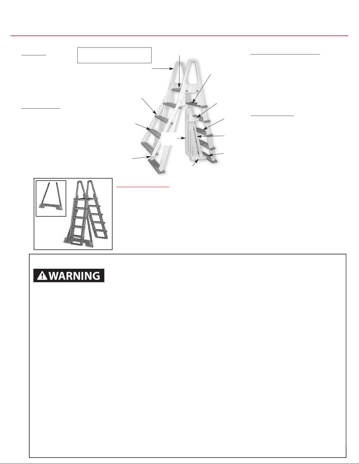
Parts List
4 - Handrail / Leg
2 - Bottom Treads
8 - Upper Treads
1 - Left Tread Connector
1 - Right Tread Connector
1 - Deck Platform with
4 wedges attached
Hardware Pack
26- #10 x 1-1/4” Screw
2 - 1/4 - 20 x 3-1/4” Bolt
6 - 1/4” Washer
2 - 1/4” Nylon Nut
2 - 1/4 - 20 x 2-1/4” Bolt
2 - Hex Nut
4 - Push in Plug (white)
2 - Adjustable Braces
1 - Cable Lock Set
LAK KIT
Use a little liquid soap to help
with ladder assembly.
Deck Platform
Handrail/Leg
Adjustable
Brace
(As shown
in Step #13)
Left Tread
Connector
Upper
Brace
Upper
Upper
Tread
Tread
Large
Barrier
Right Tread
Connector
Small
Barrier
Bottom
Tread
Lower Base
IMPORTANT: LADDER ADAPTER KIT
LAK kit ts Confer A-frame ladders for use with non-traditional
metal framed swimming pools with a wall height of 48” - 54”.
Use with models: 7100b, 7100x, 7000x, 7000b, 7200 and 8100X.
Not for use with inflatable pools.
Tools Needed for Assembly
* - Hammer or mallet
* - Cordless Drill
* - 1/8” & 9/32” Drill bits
* - Phillips Screwdriver
* - Pliers
* - 7/16” wrench or adjustable wrench
* - Liquid soap or lubricant
* - Battery operated drill motor
Barrier Parts List
(Included in Hardware Pack)
4 - #10 x 1-1/4” screws
1 - Strip of 4 Foam Pads
1 - Large Barrier Section
1 - Small Barrier Section
1 - Upper Brace
1 - Lower Base
OPTIONAL CONVERSION KIT
To easily convert your A-frame ladder to a deck/inpool ladder order
our #CK100-X conversion kit. The kit includes all parts and
hardware needed.
Safe Installation
To reduce the risk of electrocution, drowning, entrapment, falls, or other
serious injury or death:
Check building codes/permitting. Consult your local Building Department before installation of your pool and
2
equipment. Pool/equipment installation must comply with the codes of the authority having jurisdiction and
may require permits (e.g., building, plumbing, electrical, zoning, etc.).
Use for intended purpose only
• Use only as a swimming pool ladder.
• This ladder is designed and manufactured for a specic pool wall height and/or deck of the pool - check
product specication and the height of your pool.
Check that you have all required parts. Check the contents of the carton with the Parts List for this ladder.
All parts and hardware are required. If any parts are missing, DO NOT attempt to assemble or install
the ladder. Instead, call Toll Free U.S. - 800-635-3213 or visit our web site at www.conferladders.com for
assistance.
Select an appropriate location - The ladder must be located on a level, solid base and in a location that will
be in full view of competent adult supervision when in use.
Follow all instructions
• For stable, correct assembly and installation, all instructions must be followed completely and in the
sequence shown.
• Follow the manufacturer’s recommendations for the safe use of all hand tools and equipment used during
installation.
Cordless drill only - no corded drills near pool. Use a cordless drill for assembly and installation. To reduce
the risk of electrocution, NEVER use a corded drill in or around a pool.
Lift safely. When lifting awkward or heavy loads, have another person help you.
Double check after installation
• Before using the product, after assembly and installation, go over the instructions and procedures again to
make sure nothing has been overlooked.
• Make sure that safety labels are installed and legible.
Deck cannot be higher than the pool top ledge.
Page 3
Snap Small
and Large
Barrier
Sections into
slots on
Lower Base
as shown.
Step 9.
Large
Barrier
Small
Barrier
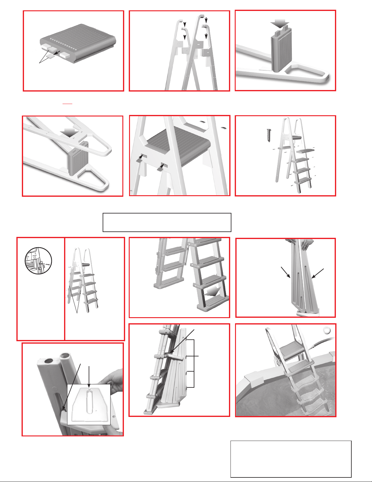
IMPORTANT: Remove the wedges from the deck platform protrusions and SAVE
for step 5.
Slide the handrail/ legs together as shown. Apply
liquid soap or spray lubricant to aid assembly.
Twist and save. Pliers may be
useful to aid in removal.
Step 3.
Place one handrail/leg assembly on a clean
at surface and push the deck platform protrusions
in the opening.
Step 4.
Repeat the process with the second handrail/
leg assembly, pushing rmly onto the deck
protrusions to ensure a secure t.
Step 5.
Insert the four wedges that were saved from
step 1, into the top of the openings as shown.
Insert wedges
Push down rmly.
Push down rmly.
Step 6.
Slide ve upper treads into position so they
are resting on the double nubs of the legs (as
shown in the diagram). Secure the treads to
the legs using the #10 x 1-1/4” screws (two
per tread), through the pre-drilled holes.
Deck Platform
Handrail/Leg
Left Tread
Connector
Upper
Tread
Right Tread
Connector
Adjustable
Brace
(As shown
in Step #13)
Upper
Brace
Upper
Tread
Bottom
Tread
Lower Base
Large
Barrier
Small
Barrier
Step 7a.
1/4” Nylon
Nut
1/4" Washer
Separate Barrier sections at the top slightly and
position Upper Brace over Small Barrier Section.
Next, spread the “ngers” on the Upper Brace and
slide into position on the Large Barrier Section.
Hardware Pack
26 - #10 x 1-1/4" screw
2 - 1/4 - 20 x 3-1/4" Bolt
6 - 1/4" Washer
2 - 1/4" Nylon Nut
2 - 1/4 - 20 x 2-1/4" Bolt
2 - Hex Nut
4 - Push in Plug (white)
2 - Adjustable Braces
1 - Cable Lock Set
Tools Needed for Assembly
* - Hammer or mallet
* - Cordless Drill Motor
* - 1/8” & 9/32” Drill Bits
* - Phillips screwdriver bit
* - Pliers
* - 7/16” wrench or adjustable wrench
* - Dish liquid or spray lubricant
Barrier Parts List (if included)
(Included in Hardware Pack)
4 - #10 x 1-1/4” screws
1 - Strip of 4 Foam Pads
1 - Large Barrier Section
1 - Small Barrier Section
1 - Upper Brace
1 - Lower Base
Model #7000X
“ELIMINATOR” A-FRAME LADDER
Adjustable to fit 48” to 54” Rigid-Framed Above Ground Pools
ASSEMBLY INSTRUCTIONS - PLEASE READ BEFORE ATTEMPTING ASSEMBLY
Parts List
4 - Handrail / Leg
2 - Bottom Treads
8 - Upper Treads
1 - Left Tread Connector
1 - Right Tread Connector
1 - Deck Platform with
4 wedges attached
If missing parts call - Toll free U.S. - 866-396-2968 or www.conferladders.com
Step 10.
NOTE: Ladder MUST be lled with water to prevent oating.
Winterizing: To winterize your ladder unfasten the ladder from the deck and pull the ladder from the
pool. Remove the two plugs and lay the ladder on its side to allow the majority of the water to drain out
of it. A small amount of water left in the ladder will not cause any damage. Replace the plugs into the fill
holes so that they do not get lost. The ladder may be left outside.
Snap Small
and Large
Barrier
Sections into
slots on
Lower Base
as shown.
Step 9.
Large
Barrier
Small
Barrier
Step 1. Step 2.
Step 7.
treads into position on the ladder legs.
Slide the three remaining upper
Step 7a.
Step 7b.
1/4”20 x 3-1/4”
1/4" Washer
Bolt
Tread connectors
holes in the ends of the treads.
Simply drive the screws into
the ends of the treads.
1/4” Nylon
Nut
Position the right and left
hand tread connectors
onto the ends of the
treads and fasten them
to the ladder legs with
the hardware as shown
in diagram 7a above.
Tighten the hardware
securely but do not over
tighten, to allow treads to
swing up easily.
Step 10.
Attach the tread
connector to
the ends of
each tread
using #10 x
1-1/4” screws
(four per tread).
Note: the
holes in the
tread
connectors
will not line
up with the
Fingers
WARNING! Using a corded drill near pool
may result in electrocution.
Step 8.
Stand here
Attach
Bottom
treads
Stand on one of the upper
treads to snap the legs into
the bottom tread.
Step 11.
Stand here
Screws
Foam
Pads
Slide ve upper treads into position so they
are resting on the double nubs of the legs
(as shown in the diagram). Using a cordless
drill, secure the treads to the legs using the
#10 x 1-1/4” screws (two per tread), through
the pre-drilled holes.
Step 9.
Snap Small
and Large
Barrier
Sections into
slots on
Lower Base
as shown.
Step 12.
Large
Barrier
Small
Barrier
Separate Barrier sections at the top slightly
and position Upper Brace over Small Barrier
Section. Next, spread the “ngers” on the Upper
Brace and slide into position on the Large
Barrier Section.
3
Place the Base and Brace into position, centered,
on the bottom and fourth treads of the ladder.
Install the four (4) #10 x 1-1/4” screws (included in
hardware pack) on a slight angle, rst in the
Upper brace, then in the Lower Base. Install the
self-adhering foam strips to the Large Barrier
Section as shown in diagram.
Place the ladder in the pool and ll legs with water
through the openings with a hose. Then plug the
holes using the four push in plugs. Tilt it so the air is
released from all the submerged treads.
WARNING! Verify that your chosen location
is level, has a solid base, and will be in full
view of competent adult supervision when in
use. Ladder MUST be filled with water to
prevent floating.
Page 4
Fingers
Step 8.
Step 12.
Attach
Bottom
treads
Stand here
Stand here
Tread connectors
Step 7a.
1/4” Nylon
Nut
1/4" Washer
1/4”-
20 x 3-1/4”
Bolt
Snap Small
and Large
Barrier
Sections into
slots on
Lower Base
as shown.
Separate Barrier sections at the top slightly and
position Upper Brace over Small Barrier Section.
Next, spread the “ngers” on the Upper Brace and
slide into position on the Large Barrier Section.
Step 9.
Step 7b.
Step 10.
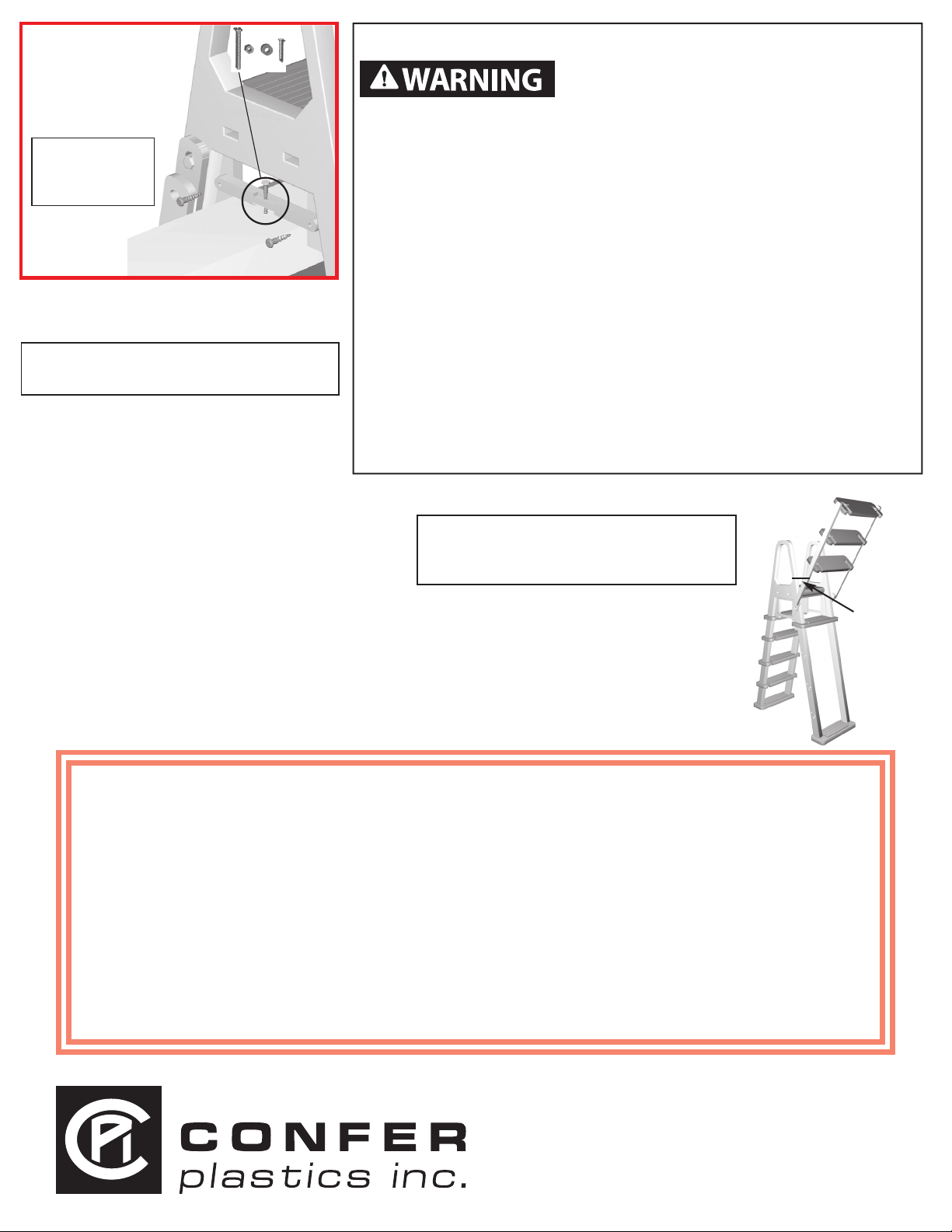
SWING UP INSTRUCTIONS
When not in use ALWAYS secure ladder by swinging
up outer treads and locking with cable lock provided.
To swing up the outer treads stand on the
bottom tread, grasp the underside of the
second lowest tread and swing it out
toward you. Swing them up until the tread
connectors drop into the preformed locks
on each leg and stay in the upright position.
To lower the treads lift them straight up to
clear the locks and carefully swing them
down toward you.
Locate
cable
lock
here
11.
Place the Base and Brace into position, centered,
on the bottom and fourth treads of the ladder.
Install the four (4) #10 x 1-1/4" screws (included in
hardware pack) on a slight angle, rst in the
Upper brace, then in the Lower Base. Install the
self-adhering foam strips to the Large Barrier
Section as shown in diagram.
Large
Barrier
Small
Barrier
Foam
Pads
Screws
Step 13.
Locate
cable
lock
here
Large
Barrier
Small
Barrier
Locate the ladder at the desired
position on the pool and place
one of the adjustable braces on
the side of the ladder so that
it rests on the top of the pool.
Secure the adjustable brace to
the ladder with two #10 x 1-1/4”
screws. Repeat for other brace.
WARNING! Using
a corded drill near
pool may result in
electrocution.
Using the braces as locators (or the deck
platform), drill two 9/32” holes through the
pool top seat. Be careful not to damage
liner or pool wall. Fasten the ladder to the
pool top using the two 1/4-20 x 2-1/4”
bolts, washers and hex nuts.
WARNING! For Maximum stability, the ladder
must be fastened to the top of the pool.
MAINTENANCE: Check the cable
lock for proper operation and lubricate if
necessary.
WINTERIZING: Unfasten the ladder
from pool top seat and remove from the
water. Remove the plugs and lay ladder on
its side to drain. It will take several minutes
for the water to drain out of the ladder rails
and treads. A small amount of water left in
ladder will not cause any damage. Replace
the plugs so they won’t get lost. To reinstall,
see installation instructions Step 12: Placing
the ladder in pool, page 3.
Safe Use
To reduce the risk of drowning, entrapment,
falls, paralysis, or other serious injury or death:
Use ladder properly.
• No diving or jumping from ladder - shallow water; risk of paralysis
or death.
• FOR ENTRY/EXIT OF POOL, FACE THE LADDER AT ALL TIMES.
• ONE PERSON ON THE LADDER/STAIR AT A TIME.
• To reduce the risk of entrapment or drowning, DO NOT swim through,
behind or around ladder.
• Illuminate the ladder when using the pool at night.
Weight limit - 300 lbs maximum. Exceeding maximum weight may cause
the ladder to fail.
Secure ladder when not in use. When pool is NOT IN USE, keep outer
treads in the up postion and locked with the Cable Lock. (See “Swing Up
Instructions”, page 4.)
Watch children at all times when they are in or around water to help
prevent drowning.
BE SURE AND SAFE. The manufacturer IS NOT responsible for improper
assembly Installation and use.
SWING UP INSTRUCTIONS:
WARNING! When pool is NOT IN USE,
keep the outer treads in the up position
and locked with the cable lock.
To swing up the outer treads, stand on the
bottom tread, grasp the underside of the
second lowest tread and swing it out toward
you. Swing them up until the tread connectors
drop into the preformed locks on each leg and
stay in the upright position. To lower the treads
lift them straight up to clear the locks and
carefully swing them down toward you.
CONFER PLASTICS INC. FIVE YEAR WARRANTY
MADE IN THE USA
4
Confer Plastics Inc. warrants their swimming pool ladders and steps to be free from defects
in workmanship for ve years from date of purchase.
DO NOT RETURN DEFECTIVE PART TO DEALER
E-MAIL CONFER PLASTICS AT: [email protected]
A PICTURE [S] OF DEFECTIVE PART, A BRIEF DESCRIPTION OF PROBLEM,
PROOF OF PURCHASE AND YOUR CONTACT INFORMATION.
INFORMATION MAY ALSO BE FAXED TO CONFER PLASTICS AT: 716-694-3102
OR MAILED TO THE ADDRESS BELOW. UPON REVIEW OF THE INFORMATION YOU
WILL BE NOTIFIED IF PART IS COVERED UNDER THE WARRANTY AND
This warranty gives you specic legal rights, and you may also have other rights which may vary from state to state.
Confer Plastics Inc., 97 Witmer Road, North Tonawanda, N.Y. 14120-2421
Printed in USA
THE SHIPPING/HANDLING CHARGES.
97 Witmer Road
North Tonawanda, New York 14120-2421
Toll Free U.S. 800-635-3213
FAX 716-694-3102
www.conferladders.com
CP-7000X REV. 2/19
 Loading...