

Conext XW+ 6848 NA, XW+ 5548 NA Owner's Manual
Conext
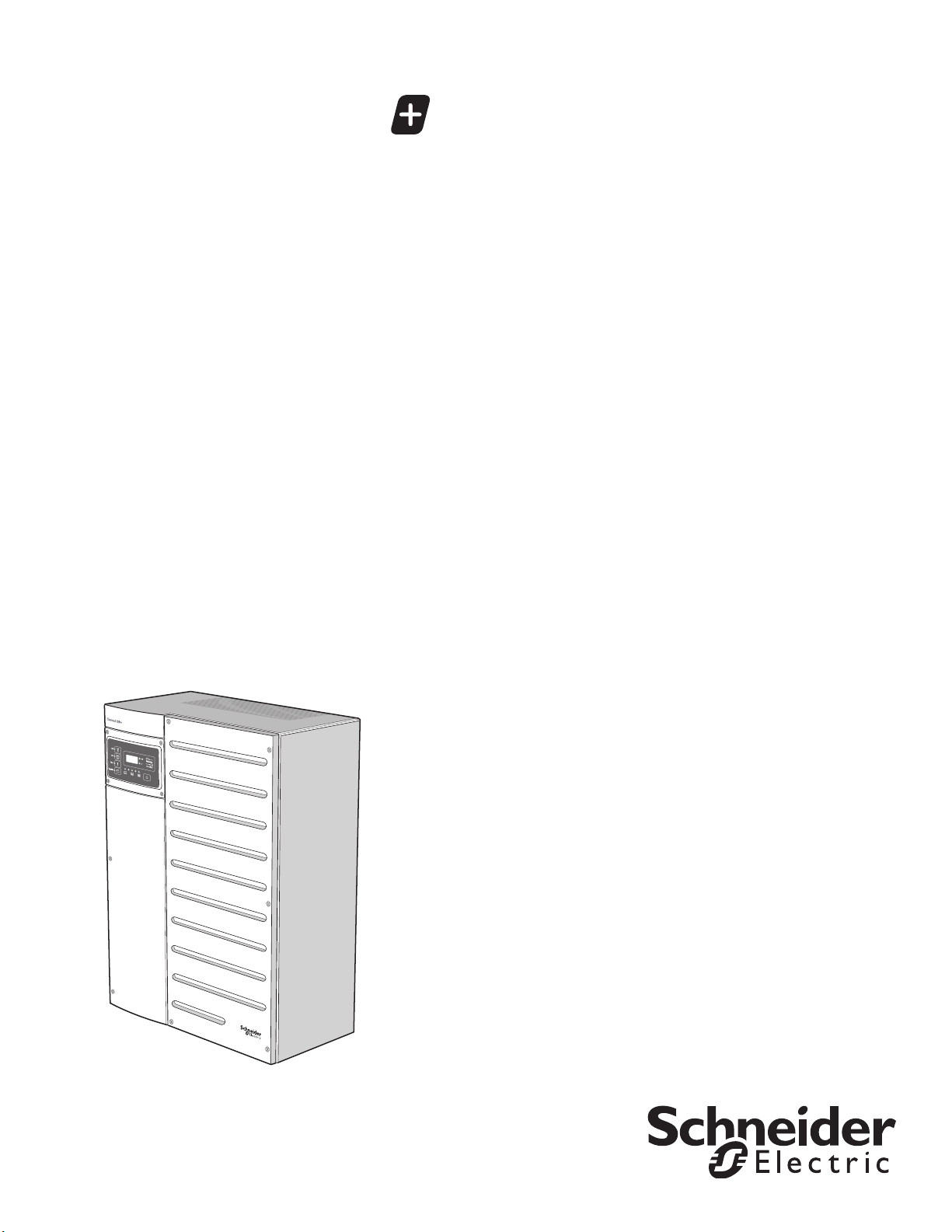
Conext XW+ 6848 NA
Conext XW+ 5548 NA
Owner’s Guide
975-0240-01-01 Revision H
November 2017
™
XW Inverter/Charger
http://solar.schneider-electric.com

Conext
Owner’s Guide
™
XW Inverter/Charger
http://solar.schneider-electric.com

Copyright and Contact
Copyright © 2007-2016 Schneider Electric. All Rights Reserved.
All trademarks are owned by Schneider Electric Industries SAS or its affiliated companies.
Exclusion for Documentation
U
NLESS SPECIFICALLY AGREED TO IN WRITING, SELLER
(A) MAKES NO WARRANTY AS TO THE ACCURACY, SUFFICIENCY OR SUITABILITY OF ANY TECHNICAL OR OTHER INFORMATION
PROVIDED IN ITS MANUALS OR OTHER DOCUMENTATION;
(
B) ASSUMES NO RESPONSIBILITY OR LIABILITY FOR LOSSES, DAMAGES, COSTS OR EXPENSES, WHETHER SPECIAL, DIRECT,
INDIRECT, CONSEQUENTIAL OR INCIDENTAL, WHICH MIGHT ARISE OUT OF THE USE OF SUCH INFORMATION. THE USE OF ANY
SUCH INFORMATION WILL BE ENTIRELY AT THE USER’S RISK; AND
(C) REMINDS YOU THAT IF THIS MANUAL IS IN ANY LANGUAGE OTHER THAN ENGLISH, ALTHOUGH STEPS HAVE BEEN TAKEN TO
MAINTAIN THE ACCURACY OF THE TRANSLATION, THE ACCURACY CANNOT BE GUARANTEED. APPROVED CONTENT IS
CONTAINED WITH THE ENGLISH LANGUAGE VERSION WHICH IS POSTED AT HTTP://SOLAR.SCHNEIDER-ELECTRIC.COM.
Date and Revision
November 2017 Revision H
Document Part Number
975-0240-01-01
Product Part Numbers
Product Part Numbers Related Product Part Numbers
865-6848-01 – Conext XW+ 6848 NA 865-1015-01 – Conext XW+ Power Distribution Panel
865-5548-01 – Conext XW+ 5548 NA 865-1025 – Conext XW+ Conduit Box
865-1020-02 – Conext XW+ Connection Kit for INV2 INV3 PDP
865-1030-1 – Conext MPPT 60 150 Solar Charge Controller
865-1032 – Conext MPPT 80 600 Solar Charge Controller
865-1050-01 – Conext System Control Panel
865-1060-01 – Conext Automatic Generator Start
865-1058 – Conext ComBox
865-1080-01 – Conext Battery Monitor
Contact Information
http://solar.schneider-electric.com
Please contact your local Schneider Electric Sales Representative or visit our website at:
http://solar.schneider-electric.com/tech-support/
Information About Your System
As soon as you open your product, record the following information and be sure to keep your proof of purchase.
Serial Number
Product Number
Purchased From
Purchase Date
_________________________________
_________________________________
_________________________________
_________________________________

About This Guide
Purpose
The purpose of this Owner’s Guide is to provide the information and procedures
necessary for configuring, operating, maintaining, and troubleshooting the
Schneider Electric Conext XW+ Inverter/Charger.
Scope
This Guide includes information about monitoring and configuring the Conext
XW+.
The Guide provides guidelines, detailed setup information, and information about
operating and troubleshooting the unit. It does not provide installation
procedures or details about particular brands of batteries, photoelectric cells, or
generators. Consult the equipment manufacturers for this information.
Audience
This Guide is intended for anyone who needs to operate, configure, and
troubleshoot the Conext XW+ Inverter/Charger. Certain configuration tasks
should only be performed by qualified personnel in consultation with your local
utility and/or an authorized dealer. Electrical equipment should be installed,
operated, serviced, and maintained only by qualified personnel. Keep
unqualified personnel away from batteries. Servicing of batteries must only be
performed or supervised by qualified personnel with knowledge of batteries and
their required precautions. Qualified personnel have training, knowledge, and
experience in:
• Installing electrical equipment
• Applying applicable installation codes
• Analyzing and reducing the hazards involved in performing electrical work
• Installing and configuring batteries
• Selecting and using Personal Protective Equipment (PPE)
No responsibility is assumed by Schneider Electric for any consequences arising
out of the use of this material.
975-0240-01-01 iii
About This Guide
Organization
This Guide is organized into four chapters and three appendices.
Chapter 1, “Introduction”, describes the operational features of the Conext XW+
Inverter/Charger.
Chapter 2, “Monitoring Operation”, contains information about monitoring Conext
XW+ Inverter/Charger operation using the inverter information panel or the
Conext System Control Panel.
Chapter 3, “Configuration” explains how to navigate through the Conext System
Control Panel menus and configure the Conext XW+ Inverter/Charger.
Chapter 4, “Troubleshooting”, contains information and procedures for identifying
and solving possible problems with the Conext XW+ Inverter/Charger.
Appendix A, “Specifications” provides the electrical and mechanical
specifications for the Conext XW+ Inverter/Charger.
Appendix B contains the default configuration settings and ranges for the Conext
XW+ Inverter/Charger. Configuration settings can be viewed and changed using
the Conext System Control Panel.
Abbreviations and Acronyms
CEC California Energy Commission
CSA Canadian Standards Association
GT Grid Tie
LCD Liquid Crystal Display
LED Light Emitting Diode
MPPT Maximum Power Point Tracking
NEC US National Electrical Code NFPA-70
PV Photovoltaic
PVGFP PV Ground Fault Protection
UL Underwriters Laboratories
VAC Volts AC
VDC Volts DC
Related Information
For information about installing the Conext XW+ Inverter/Charger, see the Conext
XW+ Inverter/Charger Installation Guide (975-0384-01-02).
You can find more information about Schneider Electric as well as its products
and services at http://solar.schneider-electric.com.
For available accessories, see “Available Conext XW+ Accessories” on page 1–
3.
iv 975-0240-01-01
Important Safety Instructions
DANGER
WARNING
CAUTION
NOTICE
READ AND SAVE THESE INSTRUCTIONS - DO NOT DISCARD
This guide contains important safety instructions for the Conext XW+ Inverter/
Charger that must be followed during operation and troubleshooting. Read and
keep this Owner’s Guide for future reference.
Read these instructions carefully and look at the equipment to become familiar
with the device before trying to install, operate, service or maintain it. The
following special messages may appear throughout this bulletin or on the
equipment to warn of potential hazards or to call attention to information that
clarifies or simplifies a procedure.
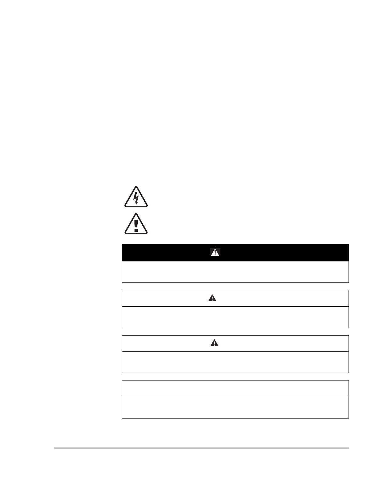
The addition of either symbol to a “Danger” or “Warning” safety label
indicates that an electrical hazard exists which will result in personal
injury if the instructions are not followed.
This is the safety alert symbol. It is used to alert you to potential
personal injury hazards. Obey all safety messages that follow this
symbol to avoid possible injury or death.
DANGER indicates a hazardous situation which, if not avoided, will result in
death or serious injury.
WARNING indicates a hazardous situation which, if not avoided, could result
in death or serious injury.
CAUTION indicates a hazardous situation which, if not avoided, could result in
minor or moderate injury.
NOTICE is used to address practices not related to physical injury. The safety
alert symbol shall not be used with this signal word.
975-0240-01-01 v

Safety
Safety Information
1. Before using the inverter, read all instructions and cautionary
markings on the unit, the batteries, and all appropriate sections of
this manual.
2. Use of accessories not recommended or sold by the manufacturer may result
in a risk of fire, electric shock, or injury to persons.
3. The inverter is designed to be permanently connected to your AC and DC
electrical systems. The manufacturer recommends that all wiring be done by
a certified technician or electrician to ensure adherence to the local and
national electrical codes applicable in your jurisdiction.
4. To avoid a risk of fire and electric shock, make sure that existing wiring is in
good condition and that wire is not undersized. Do not operate the inverter
with damaged or substandard wiring.
5. Do not operate the inverter if it has been damaged in any way.
6. This unit does not have any user-serviceable parts. Do not disassemble the
inverter except where noted for connecting wiring and cabling. See your
warranty for instructions on obtaining service. Attempting to service the unit
yourself may result in a risk of electrical shock or fire. Internal capacitors
remain charged after all power is disconnected.
7. To reduce the risk of electrical shock, disconnect both AC and DC power
from the inverter before attempting any maintenance or cleaning or working
on any components connected to the inverter. Putting the unit in Standby
mode will not reduce this risk.
8. The inverter must be provided with an equipment-grounding conductor
connected to the AC input ground.
9. Do not expose this unit to rain, snow, or liquids of any type. This product is
designed for indoor use only. Damp environments will significantly shorten
the life of this product and corrosion caused by dampness will not be
covered by the product warranty.
10. To reduce the chance of short-circuits, always use insulated tools when
installing or working with this equipment.
11. Remove personal metal items such as rings, bracelets, necklaces, and
watches when working with electrical equipment.
vi 975-0240-01-01
Safety
DANGER
DANGER
HAZARD OF ELECTRIC SHOCK, EXPLOSION, OR ARC FLASH
• Apply appropriate personal protective equipment (PPE) and follow safe
electrical work practices. See NFPA 70E or CSA Z462.
• This equipment must only be installed and serviced by qualified electrical
personnel.
• Never operate energized with covers removed
• Energized from multiple sources. Before removing covers identify all
sources, de-energize, lock-out, and tag-out and wait 2 minutes for circuits
to discharge
• Always use a properly rated voltage sensing device to confirm all circuits
are de-energized.
Failure to follow these instructions will result in death or serious injury.
HAZARD OF ELECTRIC SHOCK, EXPLOSION, OR ARC FLASH
• Disconnect negative and positive PV conductors before servicing. PV
conductors are to be treated as Hazardous Live and must be
disconnected.
• Normally GROUNDED conductors may be UNGROUNDED and
ENERGIZED when a GROUND FAULT is indicated on the front panel. Must
be serviced by qualified personnel.
Failure to follow these instructions will result in death or serious injury.
975-0240-01-01 vii
Safety
DANGER
DANGER
WARNING
Precautions When Working With Batteries
Note: Battery work and maintenance must be done by qualified personnel
knowledgeable about batteries to ensure compliance with battery handling and
maintenance safety precautions.
HAZARD OF ELECTRIC SHOCK, EXPLOSION, OR ARC FLASH
• Remove watches, rings, or other metal objects.
• This equipment must only be installed and serviced by qualified electrical
personnel.
• Keep sparks and flames away from the batteries.
• Use tools with insulated handles.
• Wear protective glasses, gloves and boots.
• Do not lay tools or other metal parts on top of batteries.
Failure to follow these instructions will result in death or serious injury.
HAZARD OF ELECTRIC SHOCK, EXPLOSION, OR ARC FLASH
• Battery Circuit Breakers must be installed according to the specifications
and requirements defined by Schneider Electric.s.
• Servicing of batteries must only be performed by qualified personnel
knowledgeable about batteries and the required precautions. Keep
unqualified personnel away from batteries.
• Disconnect the charging source prior to connecting or disconnecting
battery terminals.
Failure to follow these instructions will result in death or serious injury.
Limitations on Use
LIMITATIONS ON USE
The Conext XW+ Inverter/Charger is not intended for use in connection with
life support systems or other medical equipment or devices.
Failure to follow these instructions can result in death or serious injury.
viii 975-0240-01-01
Explosive Gas Precautions
WARNING
EXPLOSION HAZARD
This equipment is not ignition protected. To prevent fire or explosion, do not
install this product in locations that require ignition-protected equipment. This
includes any space containing gasoline-powered machinery, fuel tanks, as
well as joints, fittings, or other connections between components of the fuel
system.
Failure to follow these instructions can result in death or serious injury.
Working in the vicinity of lead acid batteries is dangerous. Batteries generate
explosive gases during normal operation. Therefore, you must read this Guide
and follow the instructions exactly before installing or using your inverter/charger.
To reduce the risk of battery explosion, follow these instructions and those
published by the battery manufacturer and the manufacturer of the equipment in
which the battery is installed.
Safety
FCC Information to the User
This equipment has been tested and found to comply with the limits for a Class B
digital device, pursuant to part 15 of the FCC Rules. These limits are designed to
provide reasonable protection against harmful interference in a residential
installation. This equipment generates, uses and can radiate radio frequency
energy and, if not installed and used in accordance with the instructions, may
cause harmful interference to radio communications. However, there is no
guarantee that interference will not occur in a particular installation. If this
equipment does cause harmful interference to radio or television reception,
which can be determined by turning the equipment off and on, the user is
encouraged to try to correct the interference by one or more of the
following measures:
• Reorient or relocate the receiving antenna.
• Increase the separation between the equipment and the receiver.
• Connect the equipment to a circuit different from that to which the receiver is
connected.
• Consult the dealer or an experienced radio/TV technician for help.
975-0240-01-01 ix

Safety
•THIS PAGE INTENTIONALLY BLANK•
x 975-0240-01-01

Contents
Important Safety Instructions
1 Introduction
Features - - - - - - - - - - - - - - - - - - - - - - - - - - - - - - - - - - - - - - - - - - - - - - - - - - - - - - - - - - - - - - - 1–2
Performance Highlights - - - - - - - - - - - - - - - - - - - - - - - - - - - - - - - - - - - - - - - - - - - - - - - - - - 1–2
Distinguishing Features - - - - - - - - - - - - - - - - - - - - - - - - - - - - - - - - - - - - - - - - - - - - - - - - - - 1–2
Xanbus™ Network Communications Protocol - - - - - - - - - - - - - - - - - - - - - - - - - - - - - - - 1–2
Available Conext XW+ Accessories - - - - - - - - - - - - - - - - - - - - - - - - - - - - - - - - - - - - - - - - - 1–3
Operation- - - - - - - - - - - - - - - - - - - - - - - - - - - - - - - - - - - - - - - - - - - - - - - - - - - - - - - - - - - - - - - 1–3
Bidirectional Theory of Operation - - - - - - - - - - - - - - - - - - - - - - - - - - - - - - - - - - - - - - - - - - - 1–3
Surge Performance - - - - - - - - - - - - - - - - - - - - - - - - - - - - - - - - - - - - - - - - - - - - - - - - - - - - - 1–7
Islanding Protection - - - - - - - - - - - - - - - - - - - - - - - - - - - - - - - - - - - - - - - - - - - - - - - - - - - - 1–7
AC Coupling - - - - - - - - - - - - - - - - - - - - - - - - - - - - - - - - - - - - - - - - - - - - - - - - - - - - - - - - - - 1–8
Multi-unit Operation - - - - - - - - - - - - - - - - - - - - - - - - - - - - - - - - - - - - - - - - - - - - - - - - - - - - - 1–9
Auxiliary Output - - - - - - - - - - - - - - - - - - - - - - - - - - - - - - - - - - - - - - - - - - - - - - - - - - - - - - 1–10
Transfer Relay - - - - - - - - - - - - - - - - - - - - - - - - - - - - - - - - - - - - - - - - - - - - - - - - - - - - - - - 1–10
K1 and K2 relay - - - - - - - - - - - - - - - - - - - - - - - - - - - - - - - - - - - - - - - - - - - - - - - - - - - - - - 1–10
Monitoring the Conext XW+ - - - - - - - - - - - - - - - - - - - - - - - - - - - - - - - - - - - - - - - - - - - - - - - - - 1–11
Conext XW+ Information Panel - - - - - - - - - - - - - - - - - - - - - - - - - - - - - - - - - - - - - - - - - - - - 1–11
Conext System Control Panel - - - - - - - - - - - - - - - - - - - - - - - - - - - - - - - - - - - - - - - - - - - - - 1–12
2 Monitoring Operation
Monitoring Operation with the Inverter Information Panel - - - - - - - - - - - - - - - - - - - - - - - - - - - - - 2–2
Monitoring AC Input Status - - - - - - - - - - - - - - - - - - - - - - - - - - - - - - - - - - - - - - - - - - - - - - - 2–2
Monitoring Conext XW+ Status - - - - - - - - - - - - - - - - - - - - - - - - - - - - - - - - - - - - - - - - - - - - - 2–3
Monitoring Charger Status - - - - - - - - - - - - - - - - - - - - - - - - - - - - - - - - - - - - - - - - - - - - - - - - 2–4
Monitoring Events - - - - - - - - - - - - - - - - - - - - - - - - - - - - - - - - - - - - - - - - - - - - - - - - - - - - - - 2–5
Equalizing Batteries - - - - - - - - - - - - - - - - - - - - - - - - - - - - - - - - - - - - - - - - - - - - - - - - - - - - 2–5
Using Startup/Shutdown/Standby Modes - - - - - - - - - - - - - - - - - - - - - - - - - - - - - - - - - - - - - 2–7
Monitoring Battery Level - - - - - - - - - - - - - - - - - - - - - - - - - - - - - - - - - - - - - - - - - - - - - - - - - 2–8
Reading the Display Screen - - - - - - - - - - - - - - - - - - - - - - - - - - - - - - - - - - - - - - - - - - - - - - - 2–9
Monitoring Operation with the Conext SCP - - - - - - - - - - - - - - - - - - - - - - - - - - - - - - - - - - - - - - 2–10
Conext System Control Panel Features - - - - - - - - - - - - - - - - - - - - - - - - - - - - - - - - - - - - - - 2–10
Using the Standby Button - - - - - - - - - - - - - - - - - - - - - - - - - - - - - - - - - - - - - - - - - - - - - - - 2–11
Conext System Control Panel Navigation - - - - - - - - - - - - - - - - - - - - - - - - - - - - - - - - - - - - 2–11
Viewing the Conext System Control Panel Home Screens - - - - - - - - - - - - - - - - - - - - - - 2–11
Viewing Other Screens - - - - - - - - - - - - - - - - - - - - - - - - - - - - - - - - - - - - - - - - - - - - - - 2–13
Reading the System Status Screen - - - - - - - - - - - - - - - - - - - - - - - - - - - - - - - - - - - - - - - - - 2–14
Reading the Conext XW+ Home Screen - - - - - - - - - - - - - - - - - - - - - - - - - - - - - - - - - - - - - 2–14
975-0240-01-01 xi

Contents
Reading the Meters Screen - - - - - - - - - - - - - - - - - - - - - - - - - - - - - - - - - - - - - - - - - - - - - - 2–18
3 Configuration
Using the Conext System Control Panel - - - - - - - - - - - - - - - - - - - - - - - - - - - - - - - - - - - - - - - - - 3–2
Conext XW+ Setup Menu - - - - - - - - - - - - - - - - - - - - - - - - - - - - - - - - - - - - - - - - - - - - - - - - 3–2
Setting the Time and Date - - - - - - - - - - - - - - - - - - - - - - - - - - - - - - - - - - - - - - - - - - - - - - - - 3–3
Using the Setup Menus - - - - - - - - - - - - - - - - - - - - - - - - - - - - - - - - - - - - - - - - - - - - - - - - - - - - 3–4
Inverter Settings Menu - - - - - - - - - - - - - - - - - - - - - - - - - - - - - - - - - - - - - - - - - - - - - - - - - - - - - 3–8
Using the Low Battery Cut Out and LBCO Delay Settings - - - - - - - - - - - - - - - - - - - - - - - - - 3–9
Using Search Mode - - - - - - - - - - - - - - - - - - - - - - - - - - - - - - - - - - - - - - - - - - - - - - - - - - - - 3–9
Charger Settings Menu - - - - - - - - - - - - - - - - - - - - - - - - - - - - - - - - - - - - - - - - - - - - - - - - - - - - 3–11
Battery Charger Functions - - - - - - - - - - - - - - - - - - - - - - - - - - - - - - - - - - - - - - - - - - - - - - - 3–12
Multi-Unit Charger Settings - - - - - - - - - - - - - - - - - - - - - - - - - - - - - - - - - - - - - - - - - - - - - - 3–12
Multi-Stage Charging Process - - - - - - - - - - - - - - - - - - - - - - - - - - - - - - - - - - - - - - - - - - - - 3–13
Equalize Charging - - - - - - - - - - - - - - - - - - - - - - - - - - - - - - - - - - - - - - - - - - - - - - - - - - - - 3–18
Equalization Procedure - - - - - - - - - - - - - - - - - - - - - - - - - - - - - - - - - - - - - - - - - - - - - - 3–20
Custom and Lithium Ion Battery Settings Sub Menus - - - - - - - - - - - - - - - - - - - - - - - - - - - - 3–21
AC Input Settings - - - - - - - - - - - - - - - - - - - - - - - - - - - - - - - - - - - - - - - - - - - - - - - - - - - - - - - - 3–24
Grid Support Settings - - - - - - - - - - - - - - - - - - - - - - - - - - - - - - - - - - - - - - - - - - - - - - - - - - - - - 3–26
Prioritizing and Managing Energy Sources with Advanced Features- - - - - - - - - - - - - - - - - - - - 3–29
Grid Support - - - - - - - - - - - - - - - - - - - - - - - - - - - - - - - - - - - - - - - - - - - - - - - - - - - - - - - - 3–29
Grid Support and Battery Charging - - - - - - - - - - - - - - - - - - - - - - - - - - - - - - - - - - - - - 3–30
Charger Block - - - - - - - - - - - - - - - - - - - - - - - - - - - - - - - - - - - - - - - - - - - - - - - - - - - - - - - 3–32
Peak Load Shaving (PLS) - - - - - - - - - - - - - - - - - - - - - - - - - - - - - - - - - - - - - - - - - - - - - - - 3–32
Time-of-Use Metering - - - - - - - - - - - - - - - - - - - - - - - - - - - - - - - - - - - - - - - - - - - - - - - 3–33
Self-Consumption - - - - - - - - - - - - - - - - - - - - - - - - - - - - - - - - - - - - - - - - - - - - - - - - - - 3–34
Generator Support Settings- - - - - - - - - - - - - - - - - - - - - - - - - - - - - - - - - - - - - - - - - - - - - - - - - 3–34
Auxiliary Output Settings- - - - - - - - - - - - - - - - - - - - - - - - - - - - - - - - - - - - - - - - - - - - - - - - - - - 3–37
Multi-Unit Config Menu - - - - - - - - - - - - - - - - - - - - - - - - - - - - - - - - - - - - - - - - - - - - - - - - - - - - 3–39
Setting the Device Name - - - - - - - - - - - - - - - - - - - - - - - - - - - - - - - - - - - - - - - - - - - - - - - - 3–41
Setting the Device Number - - - - - - - - - - - - - - - - - - - - - - - - - - - - - - - - - - - - - - - - - - - - - - 3–42
Three-Phase Configuration - - - - - - - - - - - - - - - - - - - - - - - - - - - - - - - - - - - - - - - - - - - - - - 3–43
Connections Menu - - - - - - - - - - - - - - - - - - - - - - - - - - - - - - - - - - - - - - - - - - - - - - - - - - - - - - - 3–45
Copying Settings From Another Unit - - - - - - - - - - - - - - - - - - - - - - - - - - - - - - - - - - - - - - - - - - 3–47
Resetting the Conext XW+ to Default Settings - - - - - - - - - - - - - - - - - - - - - - - - - - - - - - - - - - - 3–48
Using the Advanced Features - - - - - - - - - - - - - - - - - - - - - - - - - - - - - - - - - - - - - - - - - - - - - - - 3–49
4 Troubleshooting
General Troubleshooting Guidelines - - - - - - - - - - - - - - - - - - - - - - - - - - - - - - - - - - - - - - - - - - - 4–2
Inverter Applications - - - - - - - - - - - - - - - - - - - - - - - - - - - - - - - - - - - - - - - - - - - - - - - - - - - - - - 4–3
Resistive Loads - - - - - - - - - - - - - - - - - - - - - - - - - - - - - - - - - - - - - - - - - - - - - - - - - - - - - - - 4–3
Motor Loads - - - - - - - - - - - - - - - - - - - - - - - - - - - - - - - - - - - - - - - - - - - - - - - - - - - - - - - - - - 4–3
Problem Loads - - - - - - - - - - - - - - - - - - - - - - - - - - - - - - - - - - - - - - - - - - - - - - - - - - - - - - - - 4–3
Very Small Loads - - - - - - - - - - - - - - - - - - - - - - - - - - - - - - - - - - - - - - - - - - - - - - - - - - - 4–3
xii 975-0240-01-01

Fluorescent Lights and Power Supplies - - - - - - - - - - - - - - - - - - - - - - - - - - - - - - - - - - - 4–3
Clocks - - - - - - - - - - - - - - - - - - - - - - - - - - - - - - - - - - - - - - - - - - - - - - - - - - - - - - - - - - - 4–4
Searching - - - - - - - - - - - - - - - - - - - - - - - - - - - - - - - - - - - - - - - - - - - - - - - - - - - - - - - - - 4–4
Inverter Troubleshooting - - - - - - - - - - - - - - - - - - - - - - - - - - - - - - - - - - - - - - - - - - - - - - - - - - - - 4–4
Battery Charger Troubleshooting - - - - - - - - - - - - - - - - - - - - - - - - - - - - - - - - - - - - - - - - - - - - - - 4–7
Faults and Warnings - - - - - - - - - - - - - - - - - - - - - - - - - - - - - - - - - - - - - - - - - - - - - - - - - - - - - - 4–10
Warning Messages - - - - - - - - - - - - - - - - - - - - - - - - - - - - - - - - - - - - - - - - - - - - - - - - - - - - 4–11
Warning Types - - - - - - - - - - - - - - - - - - - - - - - - - - - - - - - - - - - - - - - - - - - - - - - - - - - - 4–11
Fault Messages - - - - - - - - - - - - - - - - - - - - - - - - - - - - - - - - - - - - - - - - - - - - - - - - - - - - - - 4–16
Fault Types - - - - - - - - - - - - - - - - - - - - - - - - - - - - - - - - - - - - - - - - - - - - - - - - - - - - - - - 4–17
Inverter Operation After Faults - - - - - - - - - - - - - - - - - - - - - - - - - - - - - - - - - - - - - - - - - 4–17
A Specifications
Electrical Specifications - - - - - - - - - - - - - - - - - - - - - - - - - - - - - - - - - - - - - - - - - - - - - - - - - - - A–2
Grid-tie Specifications - - - - - - - - - - - - - - - - - - - - - - - - - - - - - - - - - - - - - - - - - - - - - - - - - - - A–3
Response to Abnormal Grid Conditions - - - - - - - - - - - - - - - - - - - - - - - - - - - - - - - - - - - - - - A–4
Conext XW+ Overload Capability - - - - - - - - - - - - - - - - - - - - - - - - - - - - - - - - - - - - - - - - - - - A–5
Output Power Versus Ambient Temperature - - - - - - - - - - - - - - - - - - - - - - - - - - - - - - - - - - - A–8
Conext XW+ Efficiency - - - - - - - - - - - - - - - - - - - - - - - - - - - - - - - - - - - - - - - - - - - - - - - - - - A–9
Inverting Efficiency (Typical) - - - - - - - - - - - - - - - - - - - - - - - - - - - - - - - - - - - - - - - - - - - A–9
Charging Efficiency (Typical) - - - - - - - - - - - - - - - - - - - - - - - - - - - - - - - - - - - - - - - - - - A–10
Charging Efficiency Power Factor - - - - - - - - - - - - - - - - - - - - - - - - - - - - - - - - - - - - - - - A–11
Mechanical Specifications - - - - - - - - - - - - - - - - - - - - - - - - - - - - - - - - - - - - - - - - - - - - - - - - - - A–12
Accessories - - - - - - - - - - - - - - - - - - - - - - - - - - - - - - - - - - - - - - - - - - - - - - - - - - - - - - - - - - - - A–13
Contents
B Default Settings
Default Settings and Ranges - - - - - - - - - - - - - - - - - - - - - - - - - - - - - - - - - - - - - - - - - - - - - - - - B–2
Inverter Settings Menu - - - - - - - - - - - - - - - - - - - - - - - - - - - - - - - - - - - - - - - - - - - - - - - - - - - B–3
Charger Settings Menu - - - - - - - - - - - - - - - - - - - - - - - - - - - - - - - - - - - - - - - - - - - - - - - - - - B–3
Custom Settings Submenu - - - - - - - - - - - - - - - - - - - - - - - - - - - - - - - - - - - - - - - - - - - - - B–3
LithiumIon Submenu - - - - - - - - - - - - - - - - - - - - - - - - - - - - - - - - - - - - - - - - - - - - - - - - - B–4
AC Menu - - - - - - - - - - - - - - - - - - - - - - - - - - - - - - - - - - - - - - - - - - - - - - - - - - - - - - - - - - - -B–4
Grid Support Menu - - - - - - - - - - - - - - - - - - - - - - - - - - - - - - - - - - - - - - - - - - - - - - - - - - - - - B–5
Gen Support Menu - - - - - - - - - - - - - - - - - - - - - - - - - - - - - - - - - - - - - - - - - - - - - - - - - - - - - B–5
Aux Menu - - - - - - - - - - - - - - - - - - - - - - - - - - - - - - - - - - - - - - - - - - - - - - - - - - - - - - - - - - - -B–5
Connections Menu - - - - - - - - - - - - - - - - - - - - - - - - - - - - - - - - - - - - - - - - - - - - - - - - - - - - - B–6
Advanced Features Menu - - - - - - - - - - - - - - - - - - - - - - - - - - - - - - - - - - - - - - - - - - - - - - - - B–6
975-0240-01-01 xiii

Contents
•THIS PAGE INTENTIONALLY BLANK•
xiv 975-0240-01-01

1 Introduction
Chapter 1, “Introduction”, describes the
operational features of the Conext XW+
Inverter/Charger.
Topics in this chapter include:
• “Features” on page 1–2
• “Operation” on page 1–3
• “Monitoring the Conext XW+” on page 1–11

Introduction
Features
The Conext XW+ is a modular building block sine-wave inverter/charger that can
be used for residential and commercial battery based off-grid, grid backup, and
grid interactive applications.
The Conext XW+ is a self-contained DC to AC inverter, battery charger, and
integrated AC transfer switch. It is configurable in a hybrid system to operate with
generators and renewable energy sources. These configurations are capable of
extending battery based off-grid/backup autonomy.
Performance Highlights
• Excellent load starting with high 30-minute and 5-second power.
• Off-grid AC Coupling with PV inverters using frequency power curtailment
method.
• Operation in hot environments up to 70°C.
• Conversion of DC energy to AC energy for export to the utility grid.
• Power factor corrected charging minimizes AC current required for charging.
• True sine wave output.
Distinguishing Features
• Grid-interactive feature set enables time management and prioritization of
energy sources and power conversion to support advanced modes of
operation such as load shifting, self consumption and peak load shaving.
• Dual AC input connections with 60 A automatic transfer switch integrates
both utility grid and generator.
• Generator Support functionality assists small generators with heavy loads.
• Auxiliary port assist with relay switching of external devices such as battery
room fans, diversion loads and generators.
• Configurable battery parameters for customized battery charging.
• Field serviceable boards and components.
Xanbus™ Network Communications Protocol
The Conext XW+ uses Xanbus™, a network communications protocol developed
by Schneider to communicate with other Xanbus-enabled devices. You can
configure and monitor the Conext XW+ and other Xanbus-enabled devices in the
system using the Conext System Control Panel (part number 865-1050-01) or
Conext ComBox (part number 865-1058).
1–2 975-0240-01-01
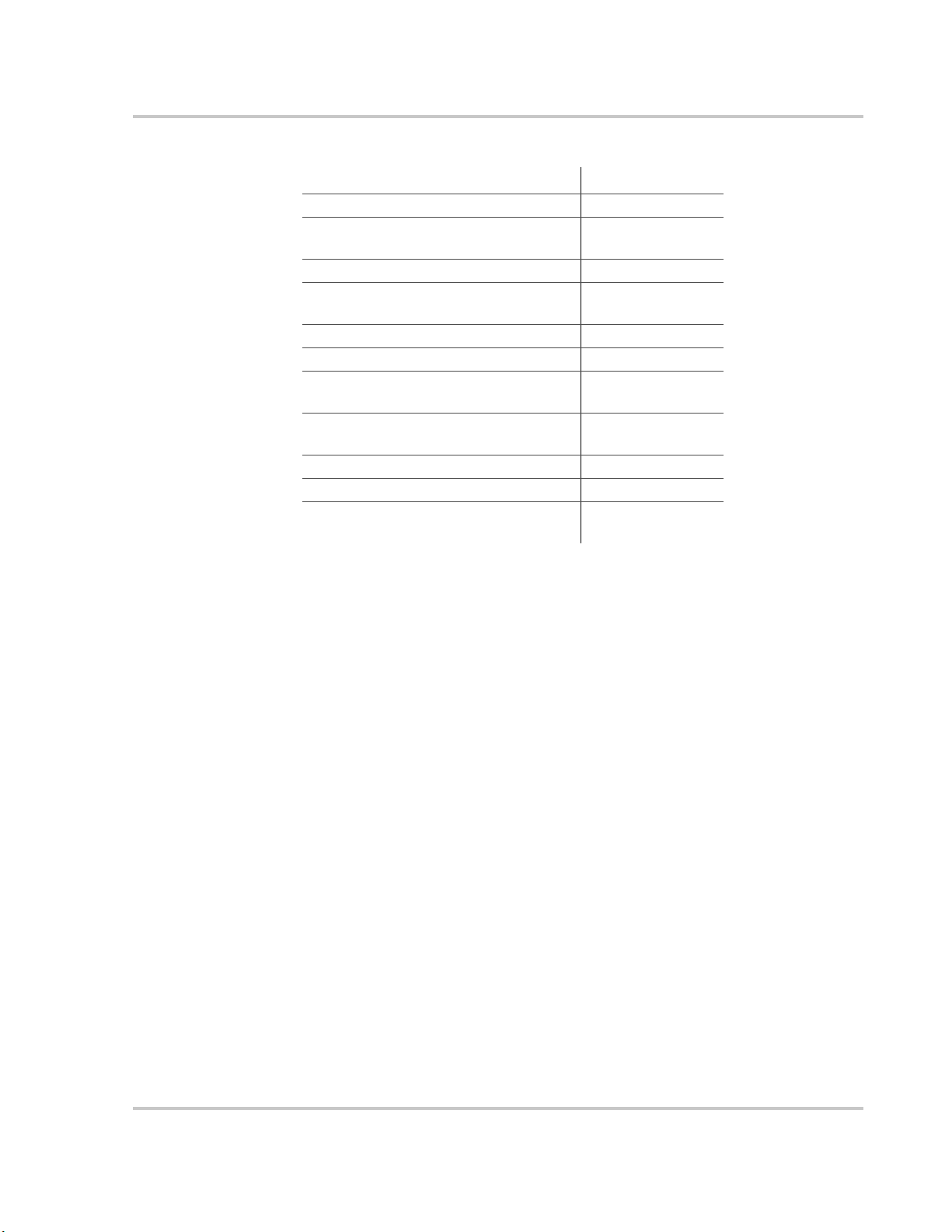
Available Conext XW+ Accessories
Accessory Part Number
Conext XW+ Power Distribution Panel 865-1015-01
Conext XW+ Power Distribution Panel
(Without AC Breakers)
Conext XW+ Conduit Box 865-1025-01
Conext XW+ Connection Kit for INV2
INV3 PDP
Conext System Control Panel 865-1050-01
Conext Automatic Generator Start 865-1060-01
Conext MPPT 60 150 Solar Charge
Controller
Conext MPPT 80 600 Solar Charge
Controller
Conext ComBox 865-1058
Conext Battery Monitor 865-1080-01
Conext XW+ PDP 120/240V 60A
Breaker Kit
Operation
865-1014-01
865-1020-02
865-1030-1
865-1032
865-1215-01
Operation
Bidirectional Theory of Operation
The Conext XW+ is a grid forming device consisting of a bidirectional inverter/
charger. It is capable of inverting DC power into AC power and controlling the
voltage and frequency of its inverter output. It will power external loads attached
to AC OUT (See Figure 1-2, “Inverting of DC to AC Connected to AC OUT” on
page 1–4).
The Conext XW+ is also capable of charging external batteries by converting AC
power into DC power (See Figure 1-3, “Charging External Batteries and
Supplying AC Out with AC Passthrough from AC1 Grid ” on page 1–5). The
Conext XW+ accepts AC power through connection AC2 for charging batteries,
usually from a generator (See Figure 1-4, “Charging External Batteries and
Supplying AC Out with AC Passthrough from AC2 Generator” on page 1–5).
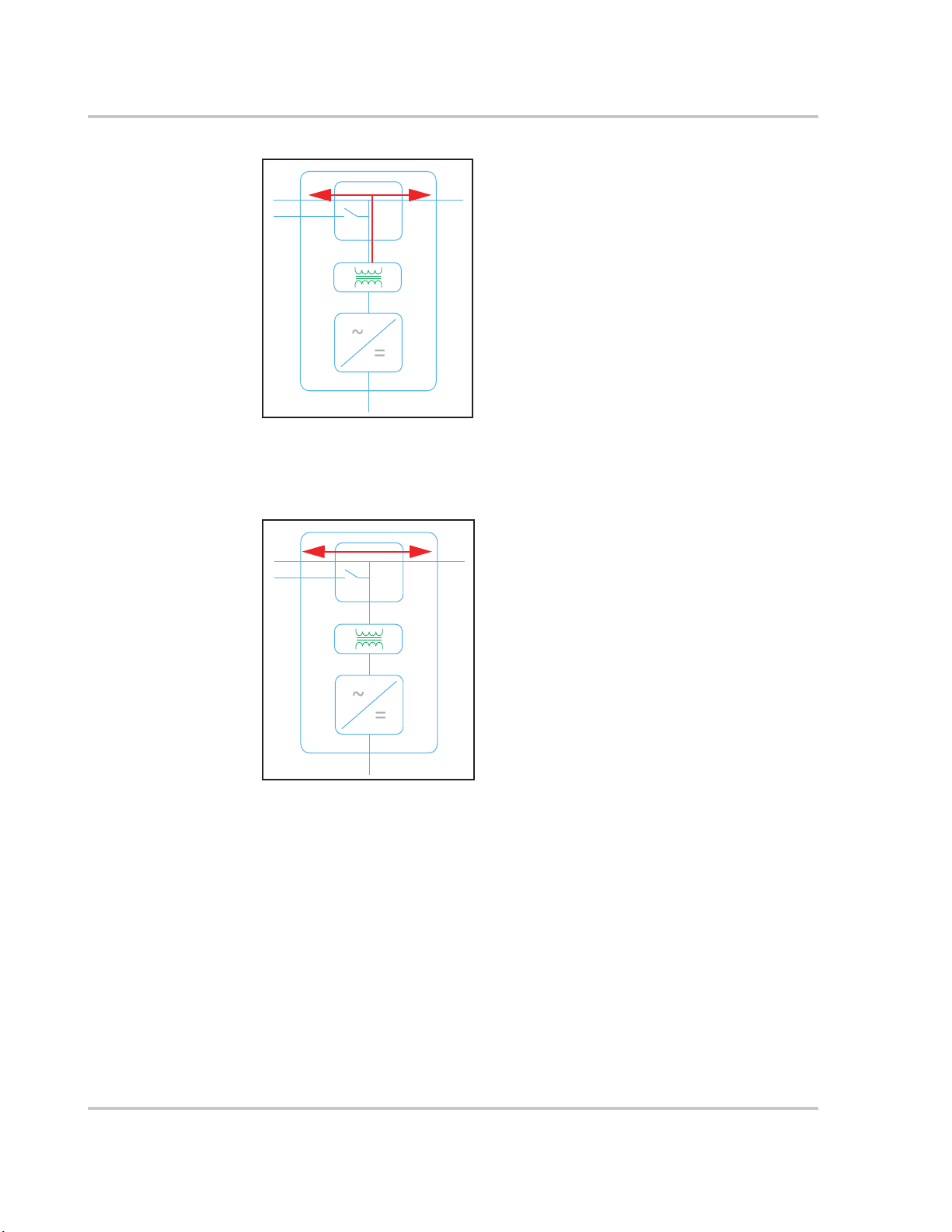
The Conext XW+ will convert externally sourced DC power into AC power for
export to the utility grid attached to its AC1 connection (See Figure 1-5,
“Converting Excess Available DC power for Export to Utility Grid (AC1) and AC
Out” on page 1–6).
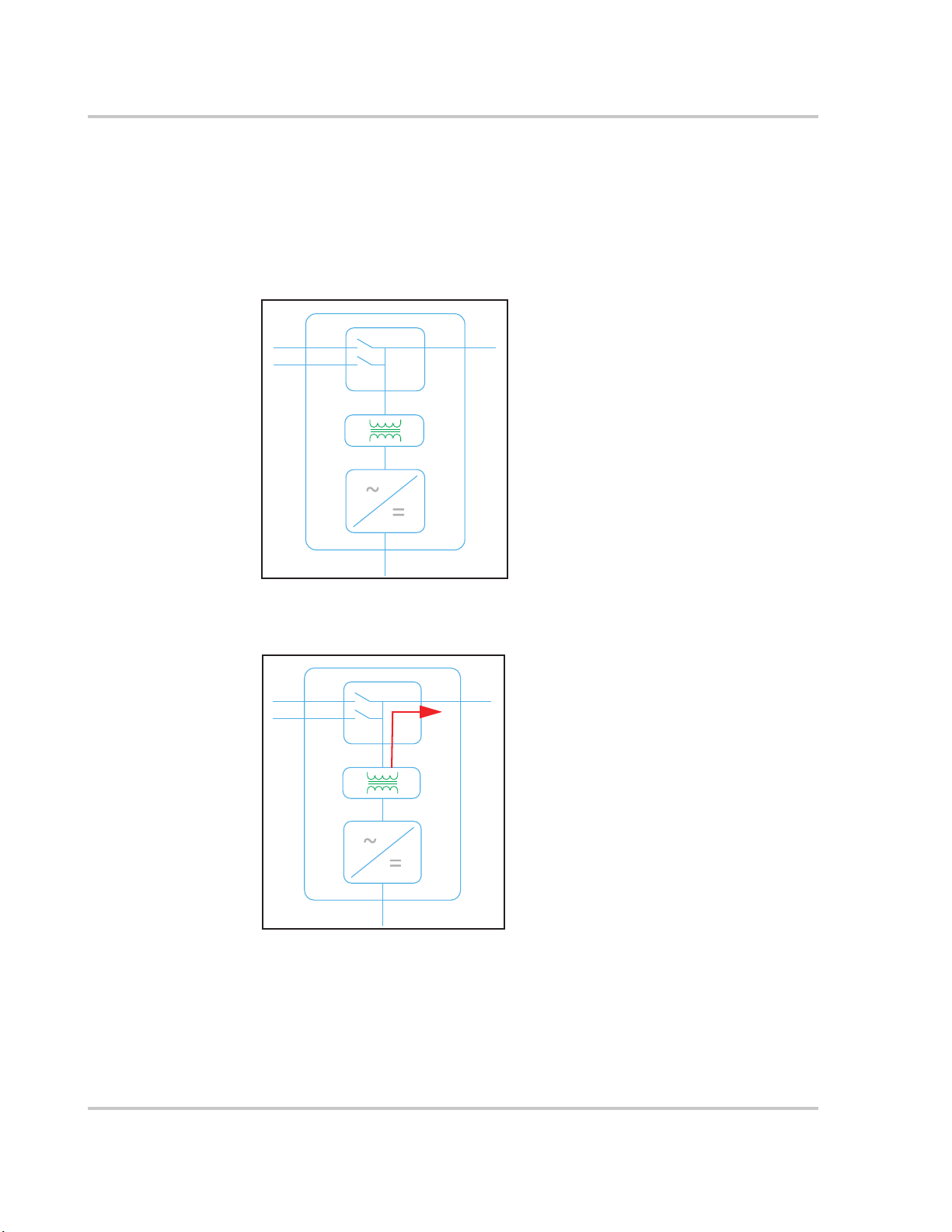
The Conext XW+ has an internal automatic transfer switch (K1, K2) which allows
either AC1 or AC2 to be connected to the inverter input, but not both at the same
time (See Figure 1-1, “Connection Points and Major Power Conversion
Components of Conext XW+ ” on page 1–4). This allows shared AC energy
during charging or to directly passthrough from AC1, or AC2, to AC Out.
975-0240-01-01 1–3
Introduction
K
2
K
1
AC Transformer
Bidirectional AC/DC
power block
AC Interface Board
AC
1
AC
2
AC
OUT
Through firmware control over power conversion and the management of K1 and
K2, Conext XW+ can facilitate advanced interaction with the utility grid to
optimize the utilization of renewable and non-renewable energy sources.
Because the Conext XW+ is a device capable of forming an AC grid signal (AC
voltage and frequency) it is also ideal for use off-grid.
The red arrows in the diagrams below represent the direction of power flow in the
respective modes of operation. These modes and other special functions will be
explained throughout this manual.
Figure 1-1 Connection Points and Major Power Conversion Components of
Conext XW+
AC
AC
1
2
AC
OUT
Figure 1-2 Inverting of DC to AC Connected to AC OUT
1–4 975-0240-01-01
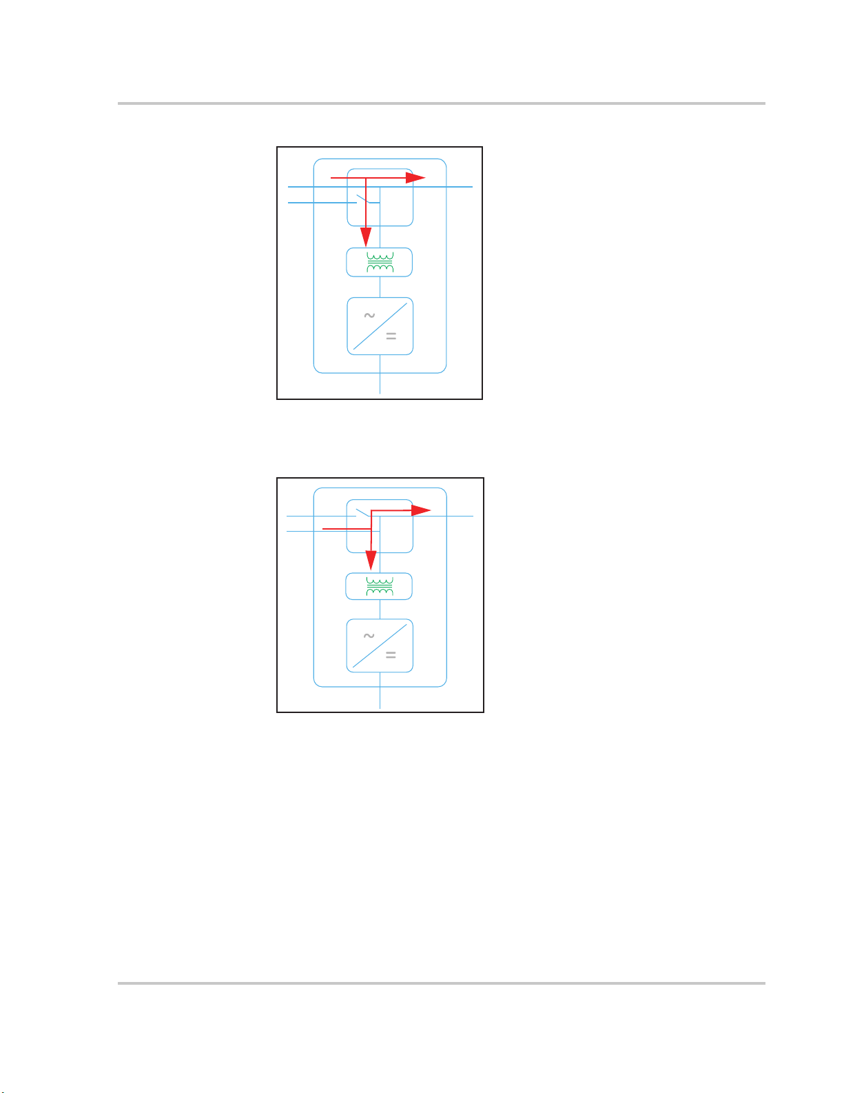
Figure 1-3 Charging External Batteries and Supplying AC Out with AC
AC
1
AC
2
AC
OUT
AC
1
AC
2
AC
OUT
Passthrough from AC1 Grid
Operation
Figure 1-4 Charging External Batteries and Supplying AC Out with AC
Passthrough from AC2 Generator
975-0240-01-01 1–5
Introduction
AC
1
AC
2
AC
OUT
AC
1
AC
2
AC
OUT
Figure 1-5 Converting Excess Available DC power for Export to Utility Grid (AC1)
and AC Out
Figure 1-6 AC Passthrough
1–6 975-0240-01-01

Surge Performance
Unlike many other inverters, the Conext XW+ helps stop voltage from sagging
dramatically during surge conditions. The Conext XW+ handles surges of over
twice its rated output power with only a minimal drop in output voltage for limited
periods of time.
Islanding Protection
Islanding protection is an essential safety feature that helps reduce harm to those
working on the utility grid from a distributed energy source such as the Conext
XW+. Islanding protection also helps to prevent loads connected to the Conext
XW+ from being damaged by a fluctuating utility grid input. The Conext XW+
uses proprietary positive feedback control to achieve anti-islanding operation
while maintaining low total harmonic distortion at the grid connection. Default
software settings are programmed into each Conext XW+ at the factory so that
they comply with applicable safety regulations (such as IEEE 1547 and UL 1741
in North America).
In some instances it may be desirable from both a utility and a customer point of
view to adjust the default anti-islanding settings. For example, the Conext XW+
may experience “nuisance trips” if the grid is weak and the voltage falls outside
the allowable range specified by regulations. It may be difficult for a utility to
adjust the grid to stop this problem. With permission from the utility, the factory
settings may be changed to allow the Conext XW+ to operate over a wider grid
voltage range. These settings must only be changed by qualified service
personnel using a special software application (Conext Configuration Tool, Order
# 865-1155-01) provided by the manufacturer.
Operation
While exporting energy, the Conext XW+ continuously monitors the utility grid
voltage and frequency. If the grid voltage or frequency move beyond the Conext
XW+ default ranges (for example, during a power surge or outage) the Conext
XW+ stops exporting energy through AC1 and disconnects from the utility. If
disconnected due to a grid voltage disturbance, five minutes is the nonadjustable minimum reconnect time during which the Conext XW+ does not
export energy through AC1 to the grid. The Fault light on the Conext XW+
information panel will indicate a utility fault. No fault code appears on the threecharacter display because the fault is with the utility grid, not with the Conext
XW+.
In addition to the information panel, the Conext System Control Panel indicates a
utility fault with the Fault light and also displays a fault message on screen (faults
F23 to F40 are utility faults—see Figure 4-6, “Fault Messages” on page 4–19).
The fault cannot be manually cleared. Utility faults will clear automatically when
the utility grid voltage and frequency return to within the ranges programmed into
the Conext XW+. If grid support is enabled and the utility voltage and frequency
come back within tolerance, the Conext XW+ information panel displays a
countdown timer for five minutes until the Conext XW+ can start interacting with
the grid again.
975-0240-01-01 1–7
Introduction
NOTICE
AC Coupling
Off-grid AC Coupled system architecture is often used to create a stand-alone
grid. Commonly this means that PV inverters are connected to the output of a
battery-based inverter/charger putting both on the same AC bus along with the
AC loads. In this scenario, the battery powered inverter charger provides the
necessary frequency and voltage to enable the PV inverter to produce power.
This type of system must be able to maintain power generation in balance with
power consumption at all times. If there is more power being generated than can
be consumed by the loads, power will flow to the inverter/charger and be
converted to DC power which flows into the battery. Once the battery reaches
capacity, power generation by the PV inverter must be curtailed to maintain the
balance between generation and consumption. As the battery bank reaches
capacity, Conext XW+ curtails PV inverter generation by raising the AC line
frequency causing compatible PV inverters to reduce their power output in an
orderly manner. This is called Active Frequency Shift Power Curtailment.
During a grid outage even a home with a grid-tie PV inverter system will be
without power because PV inverters cannot produce power without the presence
of a reference voltage and frequency. To enable the PV inverter to provide power
during a grid outage the Conext XW+ is retrofitted in front of the PV inverter. The
PV inverter is rewired from the grid connection to a critical load (sub) panel and
the AC Couple is on the Conext XW+ AC Output port. When the grid is present,
PV inverter power feeds the loads and any excess is exported by Conext XW+ to
the grid using AC1 (where permitted by the local utility). During a grid outage,
Conext XW+ anti-islanding protection prevents power from being exported to
grid on AC1. Conext XW+ then uses Active Frequency Shift Power Curtailment to
reduce the power output of compatible PV inverters, maintaining the balance of
generation and consumption.
Consult the manufacturer's specifications to determine if your PV inverter is
compatible with Active Frequency Shift Power Curtailment. Conext XW+ AC
coupling function is enabled by default (Advanced Features Menu).
AC COUPLED PV INVERTER COMPATIBILITY
AC power generated by AC coupling PV inverters with Conext XW+ must be
consumed by AC loads or used to charge batteries. As an alternative, the
excess power produced from a PV inverter can be routed to dump loads. Do
not AC couple PV inverters with the Conext XW+ that are unable to reduce,
derate or cease the excess PV inverter power in response to the changes in
AC line frequency controlled by the Conext XW+. Consult the manufacturer's
specifications of your PV inverter and confirm compatibility.
Failure to follow these instructions can result in equipment damage.
The AC coupling advanced setting should remain enabled except in cases when
the DC voltage level is allowed to have large variations and the line frequency
needs to remain constant.
1–8 975-0240-01-01

Further details about AC Coupling can be found in the document AC Coupling of
Inverters Solutions Guide (975-0240-01-01) available at http://solar.schneider-
electric.com.
Multi-unit Operation
Up to three Conext XW+ units can be installed together in a single phase configuration
with the Conext PDP (Power Distribution Panel). A maximum of four Conext XW+ units
can be installed together in a single phase configuration with the addition of a second
PDP. The PDP is an ideal optional companion for managing AC connections and
integrating a battery bank and other DC connections. Regardless of how it is installed,
the maximum number of Conext XW+ in a single phase or split phase configuration is
four.
Three Conext XW+ units can also be configured in a cluster for three-phase operation
using a single PDP (PDP is optional). Up to three clusters of three Conext XW+ units
can be installed in a three-phase configuration when using an external AC contactor.
Multiple Conext XW+ units and other Xanbus devices with common connections to
battery banks, PV arrays, the utility grid or a generator require programming during
commissioning to enable correct operation.
Inverting
Operation
For multiple units, the master Conext XW+ synchronizes operation of other connected
units using the same Xanbus network. When AC loads are present, all units produce
power, effectively sharing the load. Multiple units do not produce power together when
Search mode is enabled. See “Using Search Mode” on page 3–9.
Parallel Charging
Multiple Conext XW+ units on the same Xanbus network synchronize their charging
stages to help provide efficient charging of the battery bank. When a single unit
transitions from bulk to absorption, so do all other units. In absorption, all units must
complete the absorption stage before any of them transition to the next stage. Note that
units stop sharing charge current just before completing the bulk stage and only share
charging load during the bulk stage.
Each Conext XW+ unit provides a maximum charging current set by the Max Charge
Rate setting. The maximum current may be decreased, subject to the internal operating
temperature.
When one or more Conext Solar Charge Controllers are installed and operating in the
system, Conext XW+ units synchronize only their bulk charging stage with the charge
controllers.
Note: Equalization is device specific. Only the device(s) on which equalization was
initiated will perform the equalization. Other devices will stay in float or no-float
depending on their settings.
975-0240-01-01 1–9

Introduction
AC Transfer
Multiple Conext XW+ units monitor each other to determine the quality of AC input. If AC
input is deemed to be bad by any of the paralleled units, no transfer to AC Out occurs
and the AC LED continues to flash on each unit’s information panel until the AC is
qualified by all. If the system was in passthrough and AC fails on any unit, all units
transfer to invert simultaneously.
Faults
When the Conext XW+ detects a fault condition, the fault is displayed on the Conext
XW+. The Conext XW+ also turns on the Fault light on the Conext XW+ and inverter
information panel. A fault affects the operation of the unit. See “Fault Types” on page 4–
14 for an explanation of the different fault types.
• When a single Conext XW+ slave unit in a multi-unit system has a fault, only the
affected device shuts down.
• When a master unit has an invert mode fault that causes it to stop inverting, it is
considered a system-wide fault and all units shut down. Invert mode faults on slave
units only shut down the affected slave unit.
• All units shut down when there is a battery-related fault such as battery overtemperature or over-voltage.
Independent Operation of Features Each Conext XW+ grid-interactive feature (e.g.
enhanced grid support, grid sell, load shave and generator support) operates
independently. This enables Conext XW+ units in a multi-unit system to be configured to
perform multiple functions independently and allows greater flexibility in operating the
entire system.
Auxiliary Output
Each Conext XW+ has one programmable 12 V, 0.25 A auxiliary output that is able to
run a small fan or operate an external relay to perform other functions. Examples
include remotely starting a two-wire start generator in cases where the Xanbus-enabled
Conext AGS is not used, disconnecting external non-critical loads, or turning on a
diversion load for battery voltage regulation. See “Auxiliary Output Settings” on page 3–
37 for programme parameters.
Transfer Relay
The built-in transfer relay is rated for 60 amps. When an external AC source is detected
and qualified on either of the AC1 or AC2 inputs, the relay transfers loads from the
Conext XW+ to the external power source, and then activates the battery charger. Multiunit systems of three or more require the use of an external AC contactor to manage the
AC bus.
K1 and K2 relay
The Conext XW+ design does not allow the K1 and K2 relays to close simultaneously.
This design helps stop the generator input (AC2) from back feeding to the utility grid
(AC1).
1–10 975-0240-01-01

Monitoring the Conext XW+
AC1
AC2
Event
Equalize
kW
A
Charging
!
Inverting
Operation of the Conext XW+ can be monitored using the factory-installed inverter
information panel or the optional Conext System Control Panel and ComBox. To
configure the Conext XW+, the Conext System Control Panel or ComBox must be used.
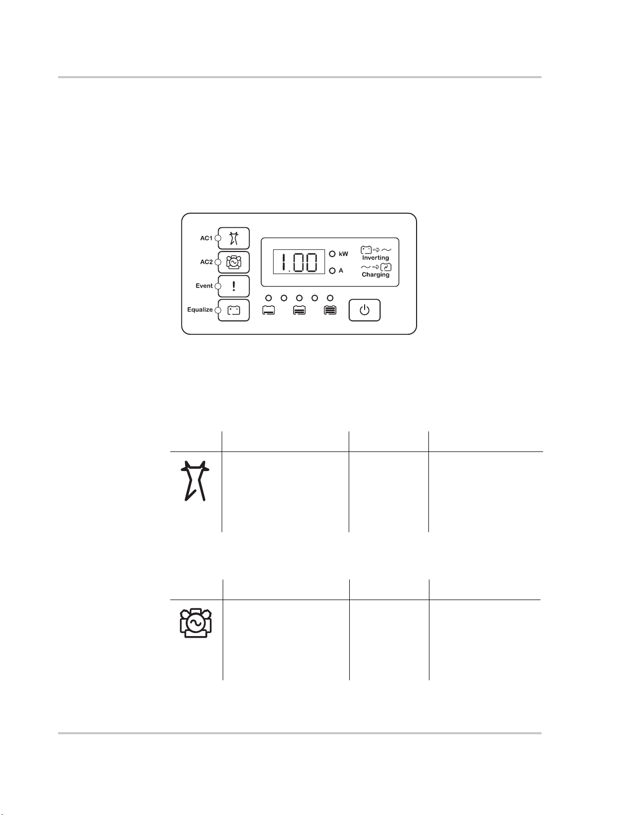
Conext XW+ Information Panel
The Conext XW+ information panel features:
• Buttons for Conext XW+ Startup/Shutdown/Standby control, clearing faults and
warnings, and battery equalization.
• A three-character display to indicate power output, charge current, anti-islanding
countdown or troubleshooting information.
• LEDs to indicate AC input status, output status, battery condition, and system
warnings/faults.
Monitoring the Conext XW+
Figure 1-7 Conext XW+ Information Panel
975-0240-01-01 1–11
Introduction
Standby
Event/Warning
Conext SCP
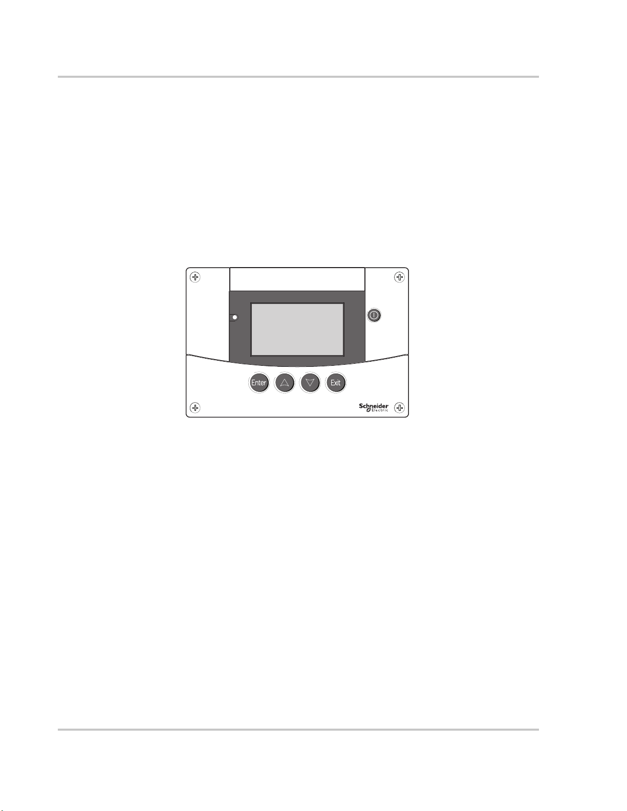
Conext System Control Panel
The Conext System Control Panel (Conext SCP) or Conext ComBox is required for
configuring the Conext XW+ and other Xanbus-enabled system components.
The Conext SCP features:
• A liquid crystal display which provides graphics and text describing real time
operation and status information.
• LED event and warning indicator.
• Internal clock which is used to control time-dependent Conext XW+ functions.
• Buttons to select configuration menus, customize Conext XW+ functions and clear
faults and warnings.
Figure 1-8 Conext System Control Panel
1–12 975-0240-01-01

2 Monitoring
Operation
Chapter 2, “Monitoring Operation”, contains
information about monitoring Conext XW+
Inverter/Charger operation using the inverter
information panel or the Conext System Control
Panel.
The topics in this chapter include:
• “Monitoring Operation with the Inverter
Information Panel” on page 2–2
• “Monitoring Operation with the Conext SCP”
on page 2–10
Monitoring Operation
Monitoring Operation with the Inverter Information Panel
The inverter information panel on each Conext XW+ monitors a single Conext
XW+. The Conext XW+ information panel displays basic information and
performs start up, shut down, equalization and standby functions. LEDs on the
information panel indicate AC input status, Conext XW+ status, battery condition,
and charging and equalization status. The Conext XW+ LEDs and threecharacter display screen indicate warning and event conditions.
Figure 2-1 Inverter Information Panel
Monitoring AC Input Status
Grid (AC1) The green Grid (AC1) LED indicates the presence and status of the
AC source connected to the AC1 input.
Symbol LED On LED Flashing LED Off
AC input is present and
qualified. The Conext
XW+ is ready to charge
batteries, pass AC
through to the loads, or
interact with the grid.
Gen (AC2) The green Gen (AC2) LED indicates the presence and status of a
generator or other auxiliary AC source on the AC2 input.
Symbol LED On LED Flashing LED Off
The AC source is present
and AC input is qualified.
The Conext XW+ is ready
to charge batteries and
pass power through to
the loads.
AC input is
present and is
being qualified.
AC input is
present and is
being qualified.
The Conext XW+ is not
connected to the grid.
AC input is not
present, or AC input is
present but not within
qualifying range.
AC input is not
present, or AC input is
present but not within
qualifying range.
2–2 975-0240-01-01
 Loading...