

CONEX CN7221 Datasheet

Data Sheet
Conexant Proprietary Information
Order No. LAN-056
Dissemination or use of this information is not permitted without the written permission of Conexant Systems, I nc.
Rev. A, March 12, 1999
LANfinity CN7221
Home Networking Physical Layer Device with
Integrated Analog Front End Circuitry
This document describes the
CN7221
Home Networking Physical Layer
(PHY) with Integrated Analog Front End (AFE). It includes device pinouts,
signal descriptions, and timing diagrams. The
CN7221
allows home
networks to operate over common telephone wires at 1 Mbps. The
CN7221
simplifies system designs and imp roves their reliability by
eliminating the need for a separate AFE comprised of discrete
components.
The
CN7221
supports the emerging home phoneline networking standard
proposed by the Home Phoneline Networking Alliance (HomePNA).
Conexant has announced plans to release a family of multifunction home
phoneline networking chipsets. The first products to be announced in this
family include the
RS7111A
1/10/100 PCI/CardBus Multifunction
Controller, the
RS7220
Home Networking PHY, the
RS7112
Multifunction
Controller with Integrated PHY, and the
CN7221
Home Networking PHY
with Integrated AFE (see Ordering Information, page 2).
The HomePNA phoneline network utilizes existing telephone wiring to
connect computers and devices without interrupting phone service.
Industry-standard home networking products will enable a variety of ho me
computing opportunities including
• shared Internet access using a single phone line
• printer/peripheral sharing
• file and application sharing
• networked gaming
The
CN7221
can be combined with the
RS7112
Multifunction PCI/CardBus
Controller and Conexant’s host-controlled (HCF) V.90/K56flex modem to
provide a variety of home networking plus 56 Kbps modem solutions.
Features
•
Supports the HomePNA 1.0 specification for
a home phoneline network
•
1 Mbps data rate
•
Integrated Analog Front End
•
Configurable transmit power level; high- and
low-power
•
Configurable transmit data rate; low- and
high-speed
•
32-pin TQFP package
HomePNA 1.0 Specification
Features
•
Meets HomePNA certification test
requirements
•
Uses existing phonelines, no new wires
required
•
Compatible with existing services
–
Internet access, voice services, and
home network coexist on the same wire
•
Robust protocol assures performance over
poor wiring infrastructure
•
FCC Part 15- and Part 68-compliant
.

Ordering Information
Product Package Device Number
CN7221
HomePNA 1.0 Physical Layer with Integrated Analog Front End
32-pin TQFP 11625-11
Related Products
RS7112
Multifunction PCI/CardBus Ethernet and HomeLAN Controll er with Integrated
HomePNA 1.0 Physical Layer and 56 Kbps HCF/HSF Modem Interface
176-pin TQFP 11623-14
RS7112-LAN
Multifunction PCI/CardBus Ethernet and HomeLAN Controll er with Integrated
HomePNA 1.0 Physical Layer Only
176-pin TQFP 11623-12
RS7111A
Multifunction PCI/CardBus Ethernet and HomeLAN Controll er with V.90 HCF Modem
Interface
176-pin TQFP 11617-14
RS7111A-LAN
Multifunction PCI/CardBus Ethernet and HomeLAN Controll er Onl y
176-pin TQFP 11617-12
RS7220
HomePNA 1.0 Physical Layer device
64-pin TQFP R8293-11
Information provided by Conexant Systems, Inc. is believed to be accurate and reliable. However, no responsibility is assumed by Conexant for its use, nor any
infringement of patents or other rights of third parties which may result from its use. No license is granted by implication or otherwise under any patent rights of
Conexant other than for circuitry embodied in Conexant products. Conexant reserves the right to change circuitry at any time without notice. This document is
subject to change without notice.
Conexant, “What’s Next in Communications Technologies,” and LANfinity are registered trademarks of Conexant Systems, Inc.
Product names or services listed in this publication are for identification purposes only, and may be trademarks or registered trademarks of their respective
companies. All other marks mentioned herein are the property of their respective holders.
1999, Conexant Systems, Inc.
All Rights Reserved
Home Networking PHY with Integrated AFE LANfinity CN7221
LAN-056, Rev. A
Conexant
3
PROPRIETARY INFORMATION
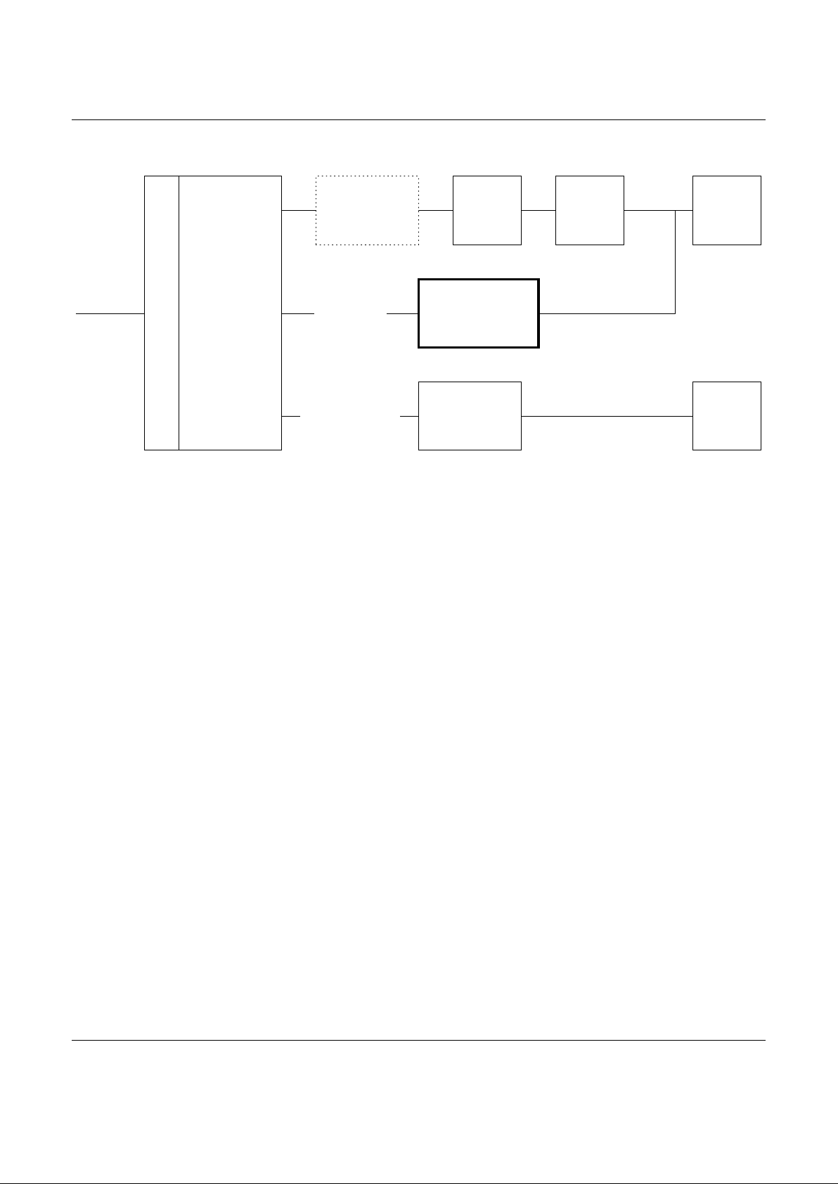
Typical Application
RS7112
Multifunction
Controller
(Ethernet MAC/V.90
Modem Combination)
P
C
I
V.90 DSP
(optional)
V.90 CODEC DAA RJ-11
CN7221
Home Networking PHY
with Inte
g
rated AFE
7-Wire Serial I/F
(7WS)
Ethernet 10 Mbps or
100 Mbps PHY/
Transceiver
Media Independent I/F
(MII)
RJ-45
LAN-056_CN7221_f1
Figure 1. Typical Application
Description
The typical application shown in Figure 1 displays a
multifunction PCI Network Interface Card (NIC). The NIC
incorporates the
RS7112
Home Networking Controller, the
CN7221
Home Networking PHY with Integrated AFE, and a
V.90 56 Kbps host-controlled modem. The
RS7112’s
7-
wire serial interface (7WS) is used to support the
CN7221
.
Home Networking
The home phoneline network is an Ethernet-compatible
LAN running over the random-tree wiring found in nearly
all homes. It does not require any hubs, routers, splitters,
filters or terminations. Initial products are PC network
interface cards, which will interface home com puters
directly to the network via an in-home telephone jack.
Home phoneline networking will also work with current
Internet access technologies, such as cable modems, V.90
and ADSL.
LANfinity CN7221 Home Networking PHY with Integrated AFE
4
Conexant
LAN-056, Rev. A
PROPRIETARY INFORMATION
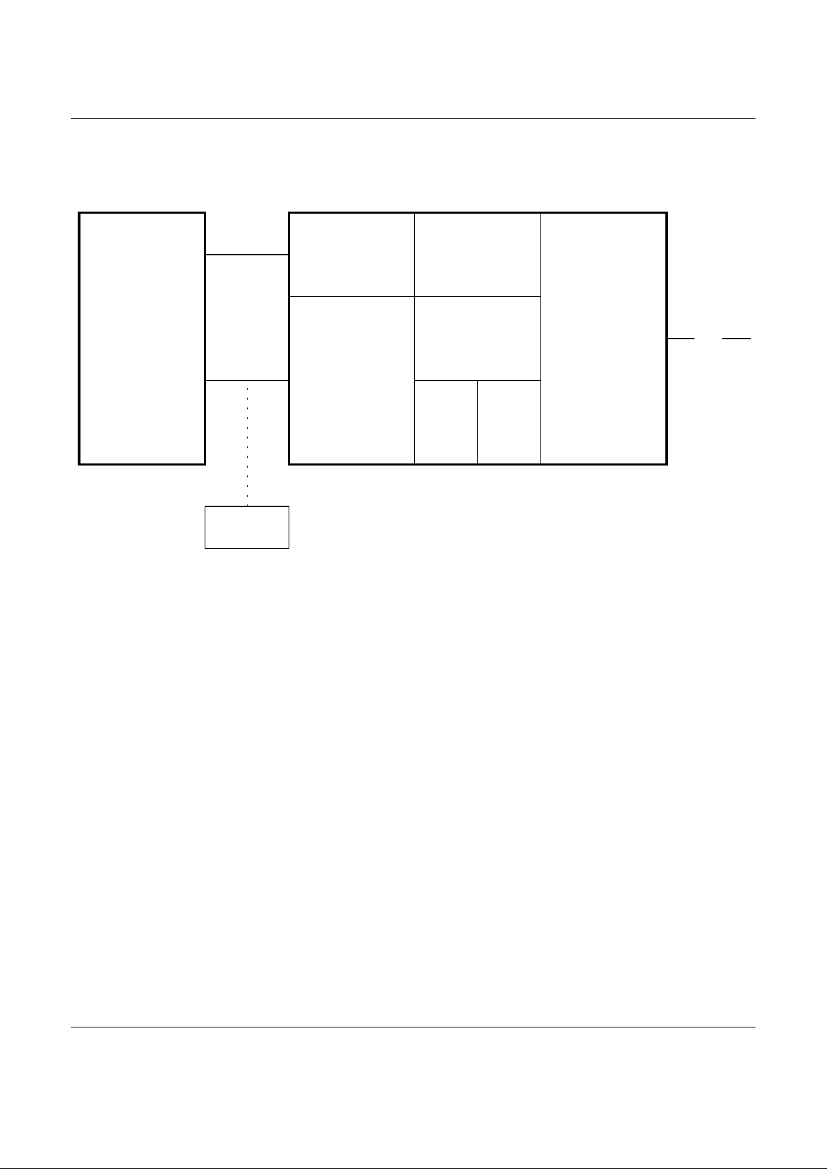
Functional Description
Interrupt Processin
g
EPROM
Interface
Registers
Physical Layer Data
Processin
g
Serial Peripheral Interface
(
SPI
)
7-Wire Serial Interface
(
7WS
)
LAN-056_CN7221_f2
Analo
g
Front End
Circuitr
y
RS7112
Bus Interface
EEPROM
CN7221 Home Networking PHY with
Integrated AFE
RJ-11
Figure 2. CN7221 Device Block Diagram
Overview
The
CN7221
PHY + AFE resides between the
RS7112
and
the physical medium and is responsible for receiving and
transmitting data on that physical medium, detecting
collisions on th e physical medium, and translating data to
and from the
RS7112
. For the purpose of this discussion,
the interface to the
RS7112
is referred to as the back end.
The discussion of the back end briefly describes the
signals involved in that interface as well as some of the
operation of those signals. More detailed information may
be gathered from the section of this document on the 7wire serial interface itself (page 5).
Back End (PHY to MAC Interface)
The back end interface is wholly defined by the seven
following signals: HLAN_TX_CLK, HLAN_TX_EN,
HLAN_TXD, HLAN_RX_CLK, HLAN_CRS, HLAN_RXD, and
HLAN_COL. The Tx signals are sampled on the falling edge
of HLAN_TX_CLK and the Rx signals are changed on the
falling edge of the HLAN_RX_CLK. HLAN_COL may change
on either edge of either the HLAN_TX_CLK or the
HLAN_RX_CLK. All signals are active high.
Due to the nature of the encoding/decoding algorithm as
well as the collision detection alg orithm used in the
CN7221,
the resulting variable bit rate forces the PHY to
“hold off” the MAC data stream by gating the
HLAN_RX_CLK and HLAN_TX_CLK signals. Gating is done
in a manner guaranteed to be glitch-free.

Home Networking PHY with Integrated AFE LANfinity CN7221
LAN-056, Rev. A
Conexant
5
PROPRIETARY INFORMATION
System Signals
The system level signals provide hardware level
initialization, configuration and status indications from the
device. They are shown in Table 1.
The HLAN_OSC pin is the 60 MHz clock input pin.
The HLAN_IRQ signal is an active-low interrupt signal
intended for use as a level-sensitive interrupt to an external
processor. All interrupt sources are maskable and capable
of being stimulated through software via the ISR and IMR
programmable registers.
Table 1. System Signals
Signal Description
HLAN_RESET# Asynchronous system reset
HLAN_IRQ# Active low processor interrupt
HLAN_OSC 60 MHz oscillator input
Seven Wire Serial (7WS) Interface
Signals
The 7-Wire serial interface provides the digital interface to
the Ethernet MAC.
The seven signals that comprise the 7WS are
HLAN_TX_CLK, HLAN_TX_EN, HLAN_TXD,
HLAN_RX_CLK, HLAN_CRS, HLAN_RXD, and HLAN_COL.
Of these, only HLAN_TX_EN and HLAN_TXD are inputs to
the PHY; the other five are outputs from the PHY. These
signals behave differently depending on which operation is
currently happening in the PHY. The operations of the PHY
are as follows:
•
Idle (no activity in either direction)
•
RxPKT (receiving data)
•
TxPKT (transmitting data).
The subsequent subsections analyze each 7WS-related
state of the PHY in detail.
Table 2. 7WS Interface Signals
Signal Description
HLAN_TX_CLK Transmit clock
HLAN_TX_EN Transmit enable
HLAN_TXD Transmit dat a
HLAN_RX_CLK Receive clock
HLAN_CRS Receive carrier sense
HLAN_RXD Receive data
HLAN_COL Collision (active high)
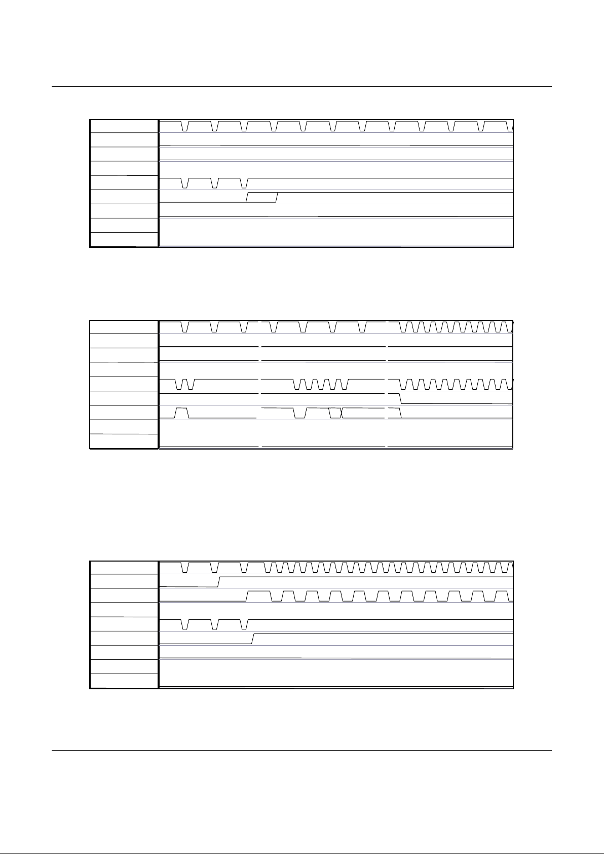
Idle State
HLAN_TX_CLK
HLAN_TX_EN
HLAN_TXD
HLAN_RX_CLK
HLAN_CRS
HLAN_RXD
HLAN_COL
HLAN_RX_CLK and HLAN_TX_CLK are synchronized to the same phase. All other signals are inactive. The two clock signals
toggle low for 116.7ns and high for 466.7ns, for an overall period of 583.3ns (about 1.7MHz).
LANfinity CN7221 Home Networking PHY with Integrated AFE
6
Conexant
LAN-056, Rev. A
PROPRIETARY INFORMATION
RxPKT Carrier Sense Asserted
HLAN_TX_CLK
HLAN_TX_EN
HLAN_TXD
HLAN_RX_CLK
HLAN_CRS
HLAN_RXD
HLAN_COL
HLAN_RX_CLK becomes disabled (and left in the high state) as soon as HLAN_CRS is asserted. HLAN_CRS may be asserted at
a multiple of 116.7ns after the rising edge of HLAN_RX_CLK (that is, 0ns, 116.7ns, 233.3ns, 350.0ns, or 466.7ns). The clock is
re-enabled about 135 uS into the packet.
RxPKT HLAN_RX_CLK Active and HLAN_CRS Cleared
HLAN_TX_CLK
HLAN_TX_EN
HLAN_TXD
HLAN_RX_CLK
HLAN_CRS
HLAN_RXD
HLAN_COL
HLAN_RX_CLK and HLAN_TX_CLK are unrelated to each other during this time. When a symbol has been received and
decoded, HLAN_RX_CLK toggles at a rate of 233.3ns (full period, 50% duty cycle) in order to shift out the three to six bits
encoded in the symbol. The middle portion of this diagram shows the end of the preamble, followed by an SFD and the
beginning of the datagram. HLAN_CRS will fall approximately 16us after the last received symbol. Once HLAN_CRS falls,
HLAN_RX_CLK and HLAN_TX_CLK are toggled continuously at 233.3ns for 97 cycles, after which the PHY returns to the Idle
state.
TxPKT HLAN_TX_EN Asserted
HLAN_TX_CLK
HLAN_TX_EN
HLAN_TXD
HLAN_RX_CLK
HLAN_CRS
HLAN_RXD
HLAN_COL
Once HLAN_TX_EN is asserted, the PHY stops HLAN_RX_CLK, asserts HLAN_CRS, and toggles HLAN_TX_CLK at 233.3ns.
 Loading...