

Conergy PTY LTD Conergy AS System Owners & Installation Manual

CONERGY PTY LTD
Conergy AS Owner &
Installation Manual

Envirosun AS Installation Manual Rev1a PVNW.docx Page 1
Table of Contents
1 Customer Information ................................................................................................................ 2
1.1 Installing your new Conergy AS System .......................................................................... 2
1.2 Conergy quality ................................................................................................................. 2
1.3 System Components ........................................................................................................ 2
1.4 Conergy model numbers explained .................................................................................. 4
1.5 Is the system suitable for extremely cold climates? ......................................................... 4
1.6 Important safety information ............................................................................................. 5
1.7 If the customer is away for a long period of time .............................................................. 5
1.8 Water discharge through the pressure valve .................................................................... 5
1.9 Hydrogen gas can accumulate! ........................................................................................ 5
2 Troubleshooting ......................................................................................................................... 6
2.1 Low solar energy input ..................................................................................................... 6
2.2 Solar collector shading ..................................................................................................... 6
2.3 AES (Booster) system not operating ................................................................................ 6
2.4 Excessive water discharge from the valves ..................................................................... 6
2.5 Hot water use higher than anticipated .............................................................................. 6
2.6 Water discharge from the frost valve ................................................................................ 7
3 System Maintenance ................................................................................................................. 8
3.1 Draining and flushing the system ..................................................................................... 8
3.2 Collector glass cleaning .................................................................................................... 8
3.3 Hail damage or broken collector glass ............................................................................. 8
3.4 Relief valves ..................................................................................................................... 9
4 Important Installation Information ............................................................................................ 10
4.1 Local Standards .............................................................................................................. 10
4.2 Safety .............................................................................................................................. 10
4.3 Water Quality .................................................................................................................. 10
4.4 Pressure Reducing Valve ............................................................................................... 11
4.5 High wind or cyclonic areas ............................................................................................ 11
4.6 Piping material ................................................................................................................ 11
4.7 Supplementary heat sources .......................................................................................... 11
4.8 Legionella requirements ................................................................................................. 12
4.9 Roof location selection ................................................................................................... 12
5 Dimensions and Technical Data ............................................................................................. 14
5.1 Collector Installation Area ............................................................................................... 14
5.2 Parts Kit Details .............................................................................................................. 15
5.3 System Weights .............................................................................................................. 16
6 Installation Instructions ............................................................................................................ 17
6.1 Installing the collectors ................................................................................................... 17
6.2 Flat roof installations ....................................................................................................... 19
6.3 Solar Flow and Return Lines .......................................................................................... 19
7 Connections at the Storage Tank ............................................................................................ 21
7.1 Connections for the PM-600 ........................................................................................... 21
7.2 Plumbing Connections .................................................................................................... 22
8 Electrical Connections ............................................................................................................. 23
8.1 Electrical connection for Electric AES (Booster) ............................................................ 23
8.2 Electrical Installation for the PM-600 .............................................................................. 24
8.3 Gas AES installation instructions .................................................................................... 26
9 Commissioning & Customer Hand Over ................................................................................. 27
9.1 Commissioning ............................................................................................................... 27
9.2 Customer Hand Over ...................................................................................................... 27
10 Warranty .................................................................................................................................. 28
11 Contact Details ........................................................................................................................ 28

1 Customer Information
Envirosun AS Installation Manual Rev1a PVNW.docx Page 2
1 CUSTOMER INFORMATION
1.1 Installing your new Conergy AS System
You are installing one of the most advanced solar water heaters in the world. This
manual provides you with the essential information needed to install the Conergy Active
System correctly. Please read it carefully and follow all the instructions. We hope you
find the following information useful.
1.2 Conergy quality
Before you can sell in Australia, or achieve any of the State or Federal Government
rebates, your product must comply with the rigorous Australian Standards for solar water
heaters. Our products comply with all these standards. The Federal Government Smallscale Renewable Energy Scheme, called STCs, is an indication of solar efficiency. If you
compare any of the Conergy products with an equal competitor model, you will find that
Conergy systems often achieve more STCs than our competitors.
1.3 System Components
The Conergy AS Solar Water Heater is supplied in kit form so that it can be assembled
and connected in various configurations to suit the installation location and user
requirements.
Typically, the kit contains the five main components of your solar water heater system.
These are:
1. Potable Water Storage Tank;
2. Solar Controller Module;
3. Solar Collector (s);
4. Ancillary Energy Support (AES) System. Please note the AES system can be
either electric or gas operated dependent on the model purchased;
5. Parts Box, which includes pipes, fittings and mounting rails to interconnect and
mount the system.
1.3.1 Storage Tank
The potable water storage tank is used to store the heated water ready for household
use. It is constructed of high quality vitreous enamel lined low carbon steel to provide
long life. The tank is insulated with a high density polyurethane material to ensure
minimal heat losses and maximum structural strength.
1.3.2 Solar Collectors
The solar collector contains a multi-tube copper water way system, bonded to a solar
absorber plate. This combination collects solar energy and transfers it to the fluid within
the collector circuit. The absorber plate system is enclosed in an insulated metal casing
covered with a high strength toughened glass sheet that protects the absorber system
from physical damage.
1.3.3 Ancillary Energy Support (AES) - also known as booster systems
The AES is used to heat part of the stored water on those occasions when there is
reduced solar activity, for example on cloudy days. The two options for an AES are
electric boosting or gas boosting.
1 Customer Information
Envirosun AS Installation Manual Rev1a PVNW.docx Page 3
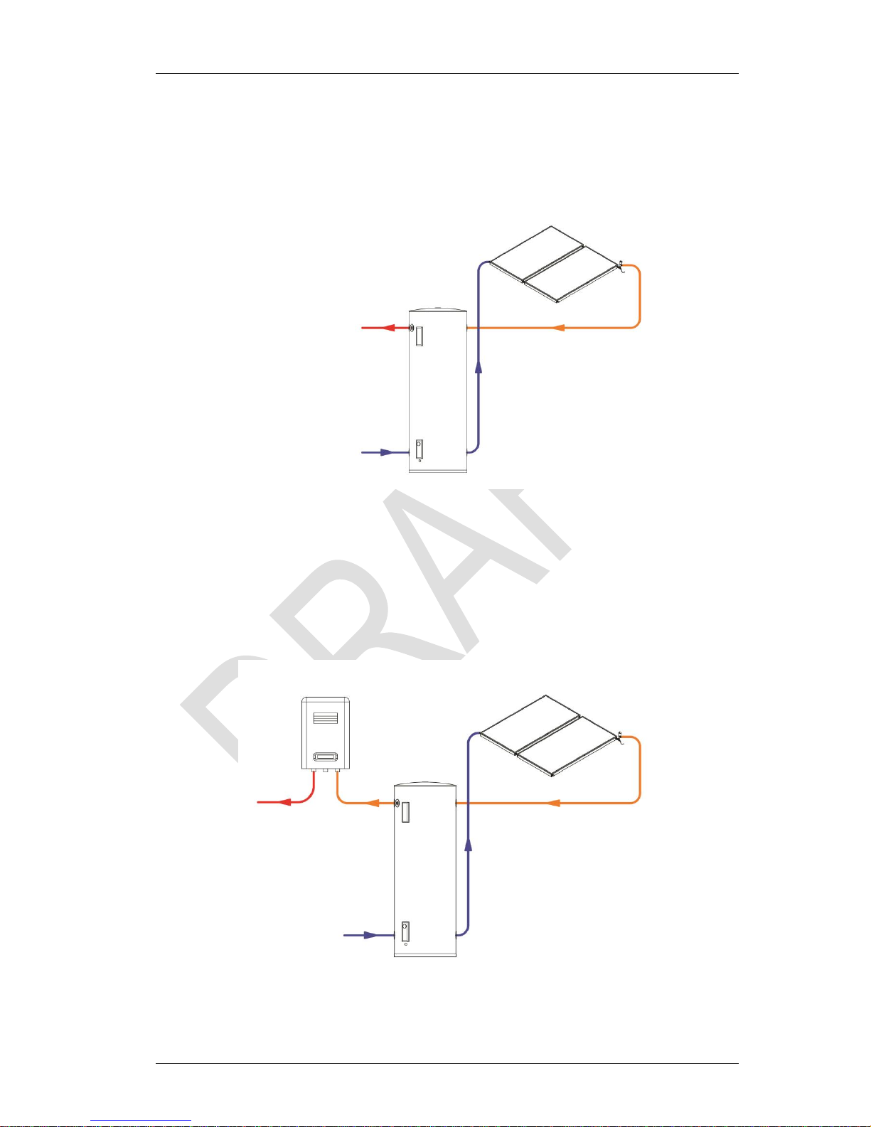
The electric element within the storage tank is used for the electric AES. This element is
automatically controlled by an internal thermostat which only allows the electric element
to operate if the water temperature in the storage tank falls below 60 °C. Even then, it will
only consume electricity until the water temperature is increased to 60 °C. At this stage it
turns off automatically.
Figure 1.3.1 Electric AES Schematic
For gas AES systems, the electric element in the storage tank is not connected to an
electricity supply. Instead, a continuous flow gas water heater is fitted adjacent the
storage tank, in series with the hot water supply from the storage tank and the household
hot water pipe work. As the hot water from the solar storage tank passes through the gas
heater its temperature is automatically monitored. If the temperature is below 70 °C, the
gas heater will add the heat required to deliver hot water of at least 70 °C. If the water
temperature is above 70 °C, the gas heater will not ignite.
Figure 1.3.2: Gas AES Schematic
1 Customer Information
Envirosun AS Installation Manual Rev1a PVNW.docx Page 4
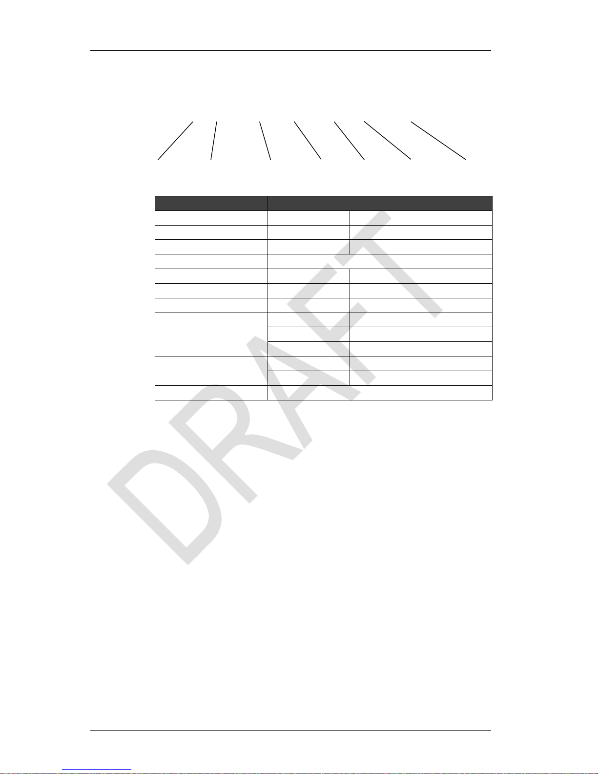
1.4 Conergy model numbers explained
XX NNN / XX / X / XNN / X / XNNXX
System Type – Nom. Volume – Collector Area – Tank Type – Booster – Tank Material – Collector
Variable
Categories
System Type AS
Active Systems (pumped)
HP
Heat Pump System Type
TS
Thermosiphon, TS
Nominal Volume
Nominal Storage Volume
Collector Area
20, 25, 40, 50, 60
Nominal Collector Area (m2x10)
Tank Type O
Open Cir
cuit
C
Closed Cir
cuit
Booster
E
Electric G
Gas
XX
Booster Rating (kWx10 or Lpm)
Tank Material
/
Designation
V
Vitreous Enamel
S
Stainless Steel
Collector Type
E20BC, E25BC or E20AA
Table 1.4.1 System Model Number
For example, AS315/40/0/E36/V/E20AA:
AS = Active System;
315 = 315 litre storage tank;
40 = 4 m² of collector area;
E36 = an electric AES with 3.6 kW rating;
V = Vitreous enamel tank;
E20AA = 2 m² selective surface solar collector, model E20AA.
1.5 Is the system suitable for extremely cold climates?
The open circuit system is not suitable for frost prone or freeze areas. If you are in a frost
prone or freeze area you must install a closed circuit system.
Whilst frost valves may be used to protect from mild damage of frosts to collectors,
installing a frost valve will not guarantee against frost damage. Damaged sustained to
the system in the event of freezing is not covered under warranty. Only closed circuit AS
models are warranted against freezing. See separate instructions and guidance on these
models.
1 Customer Information
Envirosun AS Installation Manual Rev1a PVNW.docx Page 5
If the unit is to be fitted in areas prone to frost and freezing the unit must be installed in
accordance with any relevant sustainability programme (such as the Sustainability
Victoria program).
A breach of this requirement may void the warranty in the event of damage caused
by leaking due to frost or freezing.
1.6 Important safety information
All water heaters have the ability to produce hot water very quickly. To reduce the risk of
scald injury it is recommended that a temperature control valve be fitted to the hot water
supply pipe work. This valve should be checked every 6 months to ensure its operation
and settings remain correct.
Check that the pressure & temperature relief valve drain pipe is not located where it can
cause damage if hot water is discharged.
This water heater is not intended for use by young children, infirm persons, or
persons lacking relevant skill or experience, without suitable supervision.
Children should be supervised to ensure they do not play with hot water taps or the
water heater.
1.7 If the customer is away for a long period of time
If the system is not to be used for a period of a week or more during the summer months
it is advisable to turn off the electricity supply to the booster and if practical, cover the
solar collectors. If the solar collectors are not covered there is a possibility that the high
temperature valve in the storage tank may open and disperse small amounts of hot water
for a short period to reduce the storage tank temperature while you are away. This is a
normal function and does not harm the system.
1.8 Water discharge through the pressure valve
All Conergy solar water heaters have two pressure valves located within the system
configuration. The cold water expansion control valve (ECV), located in the cold water
supply pipe, may release a small amount of water from time to time during the heating
cycle of the system. The water discharge is water expanding due to the heating process.
Normally the discharge will be less than 10 litres per day. The pressure & temperature
valve, located on the storage tank, may also release a small expansion discharge.
1.9 Hydrogen gas can accumulate!
If the hot water system is not used for two weeks or more, a quantity of highly flammable
hydrogen gas may accumulate in the water heater. To dissipate this gas safely, it is
recommended that a hot tap be turned on for several minutes at a sink, basin or bath. Do
not use a dishwasher, clothes washer or other appliance. During this procedure there
must be no smoking, open flame or any other electrical appliance operating nearby. If
hydrogen is discharged through the tap, it will probably make an unusual noise as with air
escaping. Do not place hands or any part of your body beneath the tap during this
procedure.

2 Troubleshooting
Envirosun AS Installation Manual Rev1a PVNW.docx Page 6
2 TROUBLESHOOTING
If there is not enough hot water we recommend that the following points are considered
as part of the service call. The most obvious reasons for a lack of hot water could be one
of the following.
2.1 Low solar energy input
If there have been prolonged periods of cloud or winter is approaching, it may be
necessary to reconsider the permitted boosting time for time-clock controlled systems or
to turn on the booster for systems with a booster isolation switch.
2.2 Solar collector shading
Often trees or other buildings can shade the solar collectors or there can be a dirt buildup on the glass cover. Trees should be cut back if possible or the system relocated if
removal of the shading is not possible in the present location. If the glass is dirty this
should be cleaned with standard domestic glass cleaner. If rainwater collection occurs
from the same roof on which the solar water heater is located, do not use chemical
cleaning agents to clean the collectors. Any spillage of these onto the roof could cause
contamination of water in the rainwater tank.
2.3 AES (Booster) system not operating
For electric systems the fuse or circuit breaker supplying the AES System should be
checked. If the time clock (where fitted) and the fuse or circuit breaker are operational
and the water is cold, you can turn the booster isolator on and off to see if the electricity
meter speed changes. If there is no change in speed, it indicates there may be a booster
problem. Contact your authorised Conergy dealer or installation service provider as soon
as possible.
For gas systems the gas and electric supplies to the gas heater should be checked to
ensure they are both on. If water temperature from the gas heater is below 70 °C and
both supplies are on and the gas heater does not ignite there may be a problem. Contact
your authorised Conergy dealer or installation service provider as soon as possible.
2.4 Excessive water discharge from the valves
It is normal for the Expansion Control Valve (ECV) to drip water when heating. If there is
a discharge of more than 10 litres per day from any of the systems valves, it indicates
there may be a problem with the valve or an increased water supply pressure. Contact
your authorised Conergy dealer or installation service provider as soon as possible.
2.5 Hot water use higher than anticipated
Often the hot water usage of showers, washing machines and dishwashers is
underestimated by the customer. Review these appliances to determine if the daily
usage is greater than the storage volume of the water heater. Depending on the model
and conditions, our AS system tanks contain 250 to 400 litres of hot water therefore if the
hot water load is greater than the system capacity within a short period of time, there may
be periods where the water temperature is lower than normal. It is also advisable to
inspect hot water tap washers etc. for leakage and replace if necessary.

2 Troubleshooting
Envirosun AS Installation Manual Rev1a PVNW.docx Page 7
2.6 Water discharge from the frost valve
If your system has a frost valve fitted it will be located at the bottom corner of the
collector. In temperatures that cause frost or freezing the valve will open and some water
will discharge from this valve. There is nothing that needs to be done to the valve or the
system, it is operating correctly. The water will stop discharging once the valve has
warmed enough to close again, usually as the frost clears.
Refer to section 1.5 on page 4 for more information on frost protection.

3 System Maintenance
Envirosun AS Installation Manual Rev1a PVNW.docx Page 8
3 SYSTEM MAINTENANCE
The Conergy solar water heater is designed so that there is little to do in the way of
system maintenance.
Personally inspecting or servicing any part of the system is not recommended.
Should you decide that you want to inspect the roof mounted collectors, it is essential that
you use all safety devices required to ensure your personal safety. Most importantly the
electricity supply must be turned OFF.
3.1 Draining and flushing the system
The system must be completely drained of water before any plumbing work is
commenced. This will prevent damage to the storage tank in the event of a vacuum or
excessive pressure forming at the storage tank.
The Conergy AS hot water system should be drained and flushed every five years during
a major service of the unit.
1. Turn off and isolate the power supply to the electrical element.
2. Turn off the water supply to the water heater.
3. Release excess pressure from the tank by manually opening the pressure &
temperature relief valve.
4. Disconnect the cold water supply pipe connection to the tank.
5. Fit a ½” flexible drain pipe to the cold connection at the tank. Place the open end
of the drain hose in a location where it is safe for the hot water to drain away from
the tank.
6. Manually open the pressure & temperature relief valve which will allow air into the
tank and the water within the tank will flow out via the flexible drain pipe fitted to
the cold inlet connection. Hold the valve open until the tank is empty.
7. To drain the collectors, disconnect the cold pipe from the bottom of the
collector array.
3.2 Collector glass cleaning
Glass cleaning usually occurs by natural rainfall, however if the installation is in an
industrial (or similar) area with high levels of airborne particles then a qualified person can
clean the collector glass with normal window cleaning chemicals and equipment. If
rainwater collection occurs from the same roof on which the solar water heater is located,
do not use chemical cleaning agents to clean the collectors. Any spillage of these onto
the roof could cause contamination of water in the rainwater tank.
3.3 Hail damage or broken collector glass
In the unusual case that the toughened glass collector covers are broken, Conergy does
not advise replacement of the glass. The entire panel should be replaced to maintain the
performance and integrity of the water heater. Replacement panels should be installed
by a qualified person.
 Loading...