

Conergy TS300/4/C/E24/V/E20BC, TS180/2/C/E24/V/E20BC, TS180/2/C/E24/V/E20SB, TS300/4/C/E24/V/E20SB, TS180/2/0/E24/V/F20LC Installation Manual
...
Conergy TS
Open and Closed Systems
Installation Manual
www.conergy.com.au

ENGLISH
Conergy TS
Installation Manual
1
Table of Contents
Table of Contents
Installer Information
The environmental benefits
Why Conergy?
How does the system work?
Conergy TS model number explained
Important safety information
If the customer is away for a period of time
Water discharge through the pressure valve
Troubleshooting
Low solar energy input
Solar collector shading
Booster system not operating
Excessive water discharge from the valves?
Using more hot water than anticipated?
System Maintenance
Installation Instructions
Typical open circuit assembly diagram
Typical system assembly
Connection and mounting part kits
Roof location selection
Supplementary heat sources
Common installation procedure
System installation
System diagrams and components
Plumbing connections - Open Circuit models
Plumbing connections – Closed Circuit models
Draining the storage tank
Filling the Closed Circuit jacket
Electrical installation instructions
Gas (AES) installation instructions
Commissioning & Customer Hand Over
ANNEX - Mounting frame for flat roof
1
1.1
1.2
1.3
1.4
1.5
1.6
1.7
2
2.1
2.2
2.3
2.4
2.5
3
4
4.1
4.2
4.3
4.4
4.5
4.6
4.7
4.8
4.9
4.10
4.11
4.12
4.13
4.14
5
6
2
2
2
2
4
5
5
5
6
6
6
6
6
6
7
8
8
8
9
9
10
10
11
12
21
22
23
23
25
26
27
28

ENGLISH
Conergy TS
Installation Manual
2
1 Installation Information
You are installing one of the most advanced solar water heaters in the world. This manual provides
you with the essential information needed to install the Conergy Thermosiphon System correctly.
Please read it carefully and follow all the instructions. We hope you find the following information
useful.
The environmental benefits
A Conergy solar water heater is an excellent and economic energy solution. By using the sun’s heat
to heat our water, we cut down on the amount of fossil fuels needed to be burnt to supply electricity
to do the same.
Why Conergy?
Conergy offers Australia’s largest range of renewable energy products and our company operates
in 25 countries on 5 continents. Our products are used in 100 000’s of Solar Home Systems for Hot
Water and Solar Electricity worldwide and we offer the leading products in this technology.
Before you can sell in Australia, or achieve any of the State or Federal Government rebates, your
product must comply with the rigorous Australian Standards for solar water heaters. Our products
comply with all these standards. The Federal Government Renewable Energy Certificate program,
called RECs, is an indication of solar efficiency. If you compare any of the Conergy products with
an equal competitor model, you will find that Conergy systems often achieve more RECs than our
competitors.
How does the system work?
Under normal operating conditions the potable water within the potable storage tank is heated by
the solar collectors. For example, in an open circuit system where the household hot water is in the
collector circuit, cold water is pushed downwards via the long external pipe from the storage tank to
the bottom of the solar collector. As the water is heated in the absorber by the sun, it rises to the top
of the collector then travels through the short external pipe into the storage tank.
The Conergy TS solar water heater is supplied in kit form so that the installer can assemble and
connect the solar water heater in various configurations to suit the installation location and user
requirements. Typically the kit contains the four main components of your solar water heater system
which are the potable water storage tank, the solar collector(s), the Ancillary Energy Support (AES)
System and the parts box, containing pipes fittings and mounting rails to interconnect and mount the
system. Please note the AES system can be either electric or gas operated dependent on the model
purchased.
1 Installation Information
1.1
1.2
1.3
ENGLISH
Conergy TS
Installation Manual
3
1 Installation Information
Storage Tank & Solar Collectors
The potable water storage tank is used to store the heated water ready for household use. It is
constructed using high quality vitreous enamel lined low carbon steel to provide long life. The
tank is insulated with a high density polyurethane material to ensure minimal heat losses and
maximmum structural strength.
The solar collectors contain a multi tube copper water way system bonded to a solar absorber
plate, the combination of which collects solar energy and transfers it to the fluid within the collector
circuit. The absorber plate system is enclosed in an insulated metal casing covered with a high
strength toughened glass sheet that protects the absorber system from physical damage.
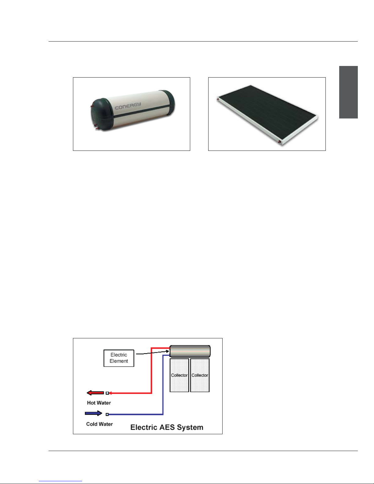
Ancillary Energy Support (AES) - Booster System
Electricity and gas are the two options for the AES system. Please assist the customer in choosing
the most suitable AES system type. An electric Ancillary Energy Support (AES) system uses an
electric element to heat part of the stored household water on those occasions when there is
reduced solar energy available e.g. cloudy days.
The electricity supply to the electric element within the storage tank is automatically controlled
by an internal thermostat which will only allow the electric element to operate if the storage tank
water temperature falls below 60 °C and will, even then, only consume electricity until the water
temperature is increased to 60 °C at which stage it turns off automatically.
1.3.1
1.3.2
Conergy TS 300 litre vitreous enamel tank
LC collector
ENGLISH
Conergy TS
Installation Manual
4
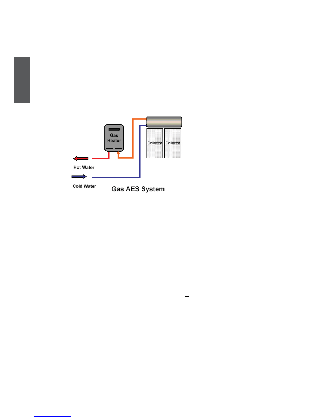
For gas AES systems the electric element in the storage tank is not connected to an electricity
supply. Instead a continuous flow gas water heater is fitted adjacent to the storage tank and in
series with the hot water supply from the storage tank and the household hot water pipe system.
As the hot water from the solar storage tank passes through the gas heater its temperature is
automatically monitored. If the temperature is below 60 °C the gas heater will add the heat required
to deliver hot water of at least 60 °C. If the water temperature is above 60 °C the gas heater is
programmed not to ignite.
1 Installation Information
1.4
Conergy TS model number explained
The model number of the system is divided into sections to describe the system which you have
installed. For example: TS300/4/0/E24/V/E20SB.
The first two digits are used to determine the system type eg. TS300/4/O/E24/V/E20SB. TS is a
thermosiphon system.
The next three digits are used to determine the tank storage volume eg. TS300/4/O/E24/V/E20SB.
In the example 300 indicates that the storage volume is a nominal 300 litres. 180 would indicate a
nominal storage volume of 180 litres.
The fourth digit indicates the nominal collector surface area eg. TS300/4/O/E24/V/E20SB. In the
example 4 indicates 4m2 and 6 would indicate 6m2.
The next figure indicates the tank model type eg. TS300/4/O/E24/V/E20SB. In the example O indicates
an open circuit tank and a C would indicate a closed circuit tank.
The next figures indicate the AES model type eg. TS300/4/O/E24/V/E20SB. In the example E24
indicates an electric 2.4kW AES a G21 would indicate a 21 litre/min gas AES.
The next figure indicates the tank construction eg. TS300/4/O/E24/V/E20SB. In the example V
indicates a vitreous enamelled tank and an S would indicate a stainless steel tank.
The final 5 figures indicate the Collector model eg. TS300/4/O/E24/V/E20SB. In the example the
collectors are model E20SB. Other models are E20BC, E25BC or F20LC.
ENGLISH
Conergy TS
Installation Manual
5
Important safety information
|
|
Hydrogen gas can accumulate!
If the hot water system is not used for two weeks or more, a quantity of hydrogen gas, which is highly
flammable, may accumulate in the water heater. To dissipate this gas safely, it is recommended that
a hot tap be turned on for several minutes at a sink, basin or bath but not a dishwasher, clothes
washer, or other appliance. During this procedure there must be no smoking, open flame or any other
electrical appliance operating nearby. If hydrogen is discharged through the tap, it will probably make
an unusual noise as with air escaping. Do not place hands or any part of your body beneath the tap
during this procedure.
If the customer is away for a period of time
If the system is not to be used for a period of a week or more during the summer months it is advisable
to turn off the electricity supply to the booster and if practical, cover the solar collectors. If the solar
collectors are not covered there is a possibility that the high temperature valve in the storage tank
may open and disperse small amounts of hot water for a short period to reduce the storage tank
temperature while you are away. This is a normal function and does not harm the system.
Water discharge through the pressure valve
All Conergy solar water heaters have two pressure valves located within the system configuration.
The cold water expansion valve, located in the cold water supply pipe, may release a small amount
of water from time to time during the heating cycle of the system. The water discharge is water
expanding due to the heating process. Normally the discharge will be less than 10 litres per day.
The pressure & temperature valve, located on the storage tank, may also release a small expansion
discharge.
All water heaters have the ability to produce hot water very quickly. To reduce the risk of scald
injury it is recommended that a temperature control valve be fitted to the hot water supply pipe
work. This valve should be checked at regular intervals to ensure its operation and settings remain
correct. Please check that the pressure & temperature relief valve relief pipe is not located where
it can cause damage if hot water is discharged.
This water heater is not intended for use by young children or infirm persons without supervision.
Young children should always be supervised to ensure that they do not play with hot water taps
or the water heater.
1.5
1.6
1.7
1 Installation Information
ENGLISH
Conergy TS
Installation Manual
6
2 Troubleshooting
2 Troubleshooting
What to check for during service calls
If there is not enough hot water we recommend that the following points are considered as part of the
service call. The most obvious reasons for a lack of hot water could be one of the following:
Low solar energy input
If there have been prolonged periods of cloud or winter is approaching, it may be necessary to
reconsider the permitted boosting time for time-clock controlled systems or to turn on the booster
for systems with a booster isolation switch.
Solar collector shading
Often trees or other buildings can shade the solar collectors or there can be a dirt build-up on the
glass cover. Trees should be cut back if possible or the system relocated if removal of the shading
is not possible in the present location. If the glass is dirty this should be cleaned with any normal
domestic glass cleaner. If rainwater collection occurs from the same roof on which the solar water
heater is located, do not use chemical cleaning agents to clean the collectors. Any spillage of these
onto the roof could cause contamination of water in the rainwater tank.
Booster system not operating
For electric systems the fuse or circuit breaker supplying the AES System should be checked. If the
time clock (where fitted) and the fuse or circuit breaker are operational and the water is cold, you can
turn the booster isolator on and off to see if the electricity meter speed changes. If there is no change
in speed, it indicates there may be a booster problem, which would need to be investigated.
For gas systems the gas and electric supplies to the gas heater should be checked to ensure they are
both on. If water temperature from the gas heater is below 60 °C and both supplies are on and the
gas heater does not ignite there may be a problem, which would need to be investigated further.
Excessive water discharge from the valves?
If there is a discharge of more than 10 litres per day from any of the systems valves, it indicates there
may be a problem with the valve or an increased water supply pressure.
Using more hot water than anticipated?
Often the hot water usage of showers, washing machines and dishwashers is underestimated by
the customer. Review these appliances to determine if the daily usage is greater than the storage
volume of the water heater. Depending on the model, our TS system tanks contain 180 or 300 litres
of hot water therefore if the customer’s usage is greater than 300 litres within a short period of time,
there may be periods where the water temperature is slightly lower than normal. It is also advisable
to inspect hot water tap washers etc. for leakage and replace if necessary.
2.1
2.2
2.3
2.4
2.5
ENGLISH
Conergy TS
Installation Manual
7
The Conergy system is designed such that there is little to do regarding system maintenance. Should
you decide that you want to inspect the roof mounted system it is essential that you use all safety
devices required to ensure your personal safety.
Glass cleaning usually occurs by natural rainfall, however if the installation is in an industrial (or
similar) area with high levels of airborne particles then a qualified person can clean the collector
glass with normal window cleaning chemicals and equipment. If rainwater collection occurs from the
same roof on which the solar water heater is located, do not use chemical cleaning agents to clean
the collectors. Any spillage of these onto the roof could cause contamination of water in the rainwater
tank.
The lever on the relief valves should be operated at least every six months. Failure to do so may result
in failure of the tank. If water does not discharge freely from the valves they should be checked and
possibly replaced. The relief valves and relief valve drain lines must not be blocked. Some water may
discharge during each heating cycle.
Every five years all safety valves should be replaced to ensure continued life and operational safety
of the system. In locations where the potable water has a Total Dissolved Solids (TDS) of greater than
600 ppm it is recommended to replace all safety valves every 3 years.
The high quality vitreous enamel lined low carbon steel tanks have a sacrificial anode for long tank
life. This anode should be inspected every few years and be replaced when it has worn out. As a
minimum it is recommended that the anode be changed every 5 years.
3 System Maintenance
3 System Maintenance
ENGLISH
Conergy TS
Installation Manual
8
Important Notes
|
|
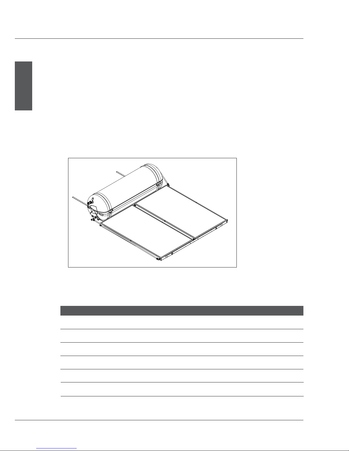
Typical open circuit assembly diagram
Typical system assembly
The table below indicates the system components:
DO NOT commence an installation until you have satisfied yourself that all safety issues
associated with working on and lifting components onto a roof have been addressed.
All work associated with the installation must comply with local authority regulations including
AS/NZS 3500.4.2. Where these installation instructions and local regulations are in conflict,
local regulations must prevail.
4 Installation Instructions
4.1
4.2
Module Number Tank Collector Model Number Tank Collector
TS180/2/0/E24/V/F20LC TS180/0/E24 1 x F20LC TS180/2/C/E24/V/E20BC TS180/C/E24 1 x E20BC
open circuit closed circuit
TS180/2/0/E24/V/E20BC TS180/0/E24 1 x E20BC TS180/2/C/E24/ V/E20SB TS180/C/E24 1 x E20SB
open circuit closed circuit
TS180/2/0/E24/V/E20SB TS180/0/E24 1 x E20SB TS300/4/C/E24/V/E20BC TS300/C/E24 2 x E20BC
open circuit closed circuit
TS300/4/0/E24/V/F20LC TS300/0/E24 2 x F20LC TS300/4/C/E24/V/E20SB TS300/C/E24 2 x E20SB
open circuit closed circuit
TS300/4/0/E24/V/E20BC TS300/0/E24 2 x E20BC
open circuit
TS300/4/0/E24/V/E20SB TS300/0/E24 2 x E20SB
open circuit
4 Installation Instructions
ENGLISH
Conergy TS
Installation Manual
9
4 Installation Instructions
4.3
4.4
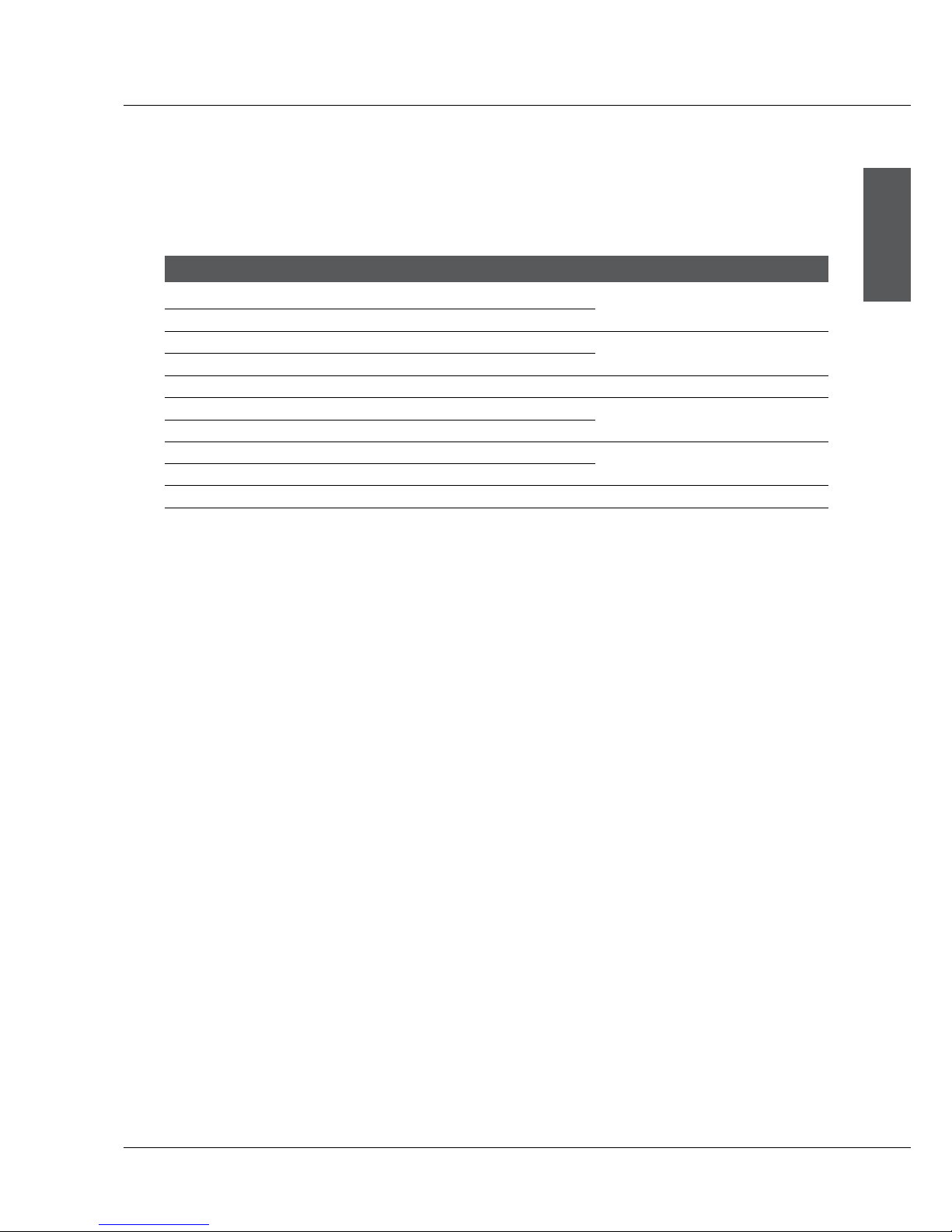
Connection and mounting part kits
The table below indicates the connection and mounting kits required for each model system:
Roof location selection
There are five major factors to consider when selecting the solar water heater installation location:
|
|
|
|
Module Number Parts Kit
TS180/2/O/E24/V/E20BC PK2050
TS180/2/O/E24/V/E20SB
TS180/2/C/E24/V/E20BC PK2051
TS180/2/C/E24/V/E20SB
TS180/2/O/E24/V/F20LC PK2052
TS300/4/O/E24/V/E20BC PK2055
TS300/4/O/E24/V/E20SB
TS300/4/C/E24/V/E20BC PK2056
TS300/4/C/E24/V/E20SB
TS300/4/O/E24/V/F20LC PK2057
For optimum performance the solar collectors need to face the equator (in Southern hemisphere
this is north and in the Northern hemisphere this is South). Installation on angles of up to 45°
away from the equator do not have a major effect on the annual solar output, consequently roof
locations which face less than 45° away from the equator are acceptable. If the collectors are
installed with an east facing bias the best solar input is achieved in the morning and if there is a
west facing bias the best solar input is in the afternoon.
Careful site inspection is required to ensure the selected location is not subjected to shading
from adjacent trees or buildings throughout the day, but particularly between 9am and 3pm, the
highest solar input times. Shadows are longer in winter than in summer so a site that is free of
shadows from adjacent objects in summer may have some shadows in winter.
The solar water heater should be located as close as possible to the location which uses the most
hot water eg. bathroom or kitchen. This is to reduce energy losses which may occur if the pipe
work between the solar water heater and the point of usage is too long.
To achieve optimum performance the solar water heater should be installed on a roof pitch of
greater than 8° and less than 30°. Installations on a roof where the roof pitch is greater than 30°
will require additional support at the storage tank to prevent it moving downward during and after
installation. If the roof pitch is less than 8° the system will require a mounting frame to increase
the pitch above 8°. Installations below 8° do not thermosiphon effectively and the collector glass
will not self clean during rainy periods.
 Loading...