

Page 1
Solar Module
Conergy PE - UL
Installation Manual
Page 2

1 Introduction
1.1 Brief description
Conergy modules are solar modules for installation in photovoltaic systems.
1.2 About this installation manual
1.2.1 Subject of this manual
This installation manual describes the procedures for installation and electrical connection of these solar modules in a
grid-connected photovoltaic system. Additional solar modules are installed with the same procedures.
1.2.2 User group
The manual is intended to be used by the system owner and by qualified persons possessing technical skills and
basic electrical, electronic and mechanical knowledge related to photovoltaic systems. Please retain this manual for
future reference.
1.2.3 Symbols
Start of a step-by-step procedure with description of the goal of the procedure. Individually numbered steps follow,
which may be interrupted by background information, illustrations or warnings.
Background and additional information or the status of a procedure. Appears between the steps of a procedure,
within the sequence/course of a procedure.
1.3 Standards and technical directives
The solar modules comply with the following standards:
| IEC 61215 ed. 2
| IEC 61730
| ULC/ORD-C1703-01 & UL 1703
1.4 Intended use
The solar modules are designed for use in photovoltaic systems. Any other use is considered improper use.
These solar modules do not comply with the technical regulations for overhead glazing and may not be used for such
applications. These solar modules are not intended for use in mobile applications (e.g. vehicles) or mar ine
applications (e.g. boats).
Intended use also includes compliance with the specifications stated in this installation manual. Conergy shall not be
held liable for damages arising from a failure to observe and follow the installation manual, particularly the safety
instructions contained in it, or from any improper use of the product.
2 Safety
2.1 Responsibilities of the owner/operator
The system operator has safety-related responsibilities. He must ensure that:
| Local codes and other applicable laws concerning required permitting as well as installation & inspecti on
requirements, rules, and regulations are followed;
| Installation is only carried out by qualified individuals with photovoltaic specialist technical knowledge and basic
knowledge of mechanical engineering;
| Electrical connection is only established by an electrical engineer;
| Persons commissioned to perform the work can evaluate their assigned tasks and recognize possible risks;
| Those commissioned to perform the work are familiar with the system components;
| Installation manual is made available during the installation;
Page 3

| Installation manual, and in particular the safety instructions, have been read and understood by the relevant
personnel before installation;
| Suitable lifting gear and tools are used for the installation;
| If replacements are required, only Conergy components are used and repairs are on ly carried out by qualified
technicians authorized by Conergy, as otherwise the warranty will be voided;
| Only components (cable, plugs, mounting parts, etc.) that are suitable for use in photovoltaic systems are used;
| Solar module is not installed near highly flammable gases or vapors because sparks could be generated;
| Solar modules are installed over a fireproof roof covering when installed on a roof;
| Sunlight is not artificially concentrated on the solar module;
| Junction box and the cable are not exposed to direct sunlight for long periods of time;
| Solar module is not in direct contact with water or exposed to moisture for long periods of time;
| Solar module is not subjected to any extreme chemical loads (e.g. emissions from production operations);
| Solar module is not subjected to mechanical loads higher than the approved levels;
| Solar module is only used in the specified ambient temperature range;
| No paint, coatings or adhesives are applied to the solar module;
| Solar module is not dismantled and none of the parts provided on delivery are removed;
| Solar modules are only transported in their original packaging.
2.2 Basic safety instructions
The following safety instructions and warnings form an essential part of this installation manual and are of
fundamental importance when handling this product.
| Make allowance for the loads that these modules may generate for the entire structure.
| Consider all loads generated by the solar modules in the static calculation for the overall structure.
| To avoid damage (e.g. broken glass) do not leave solar modules unsecured.
| Check the mechanical integrity of the solar modules prior to installation. Only use undamaged solar modu les.
| Only use mounting systems recommended by Conergy that can withstand the expected loads for snow, wind,
etc.
| Make sure no other system components impair the mechanical or electrical function of the solar modules.
| Only work in dry conditions with dry solar modules and dry tools.
| Do not drill any holes into the module frame or the glass surface and do not perform any welding work on or in
the direct vicinity of the solar module.
| To avoid burns do not touch solar modules under load without wearingprotective gear, ie. Insulating gloves,
protective eyewear, etc.
| Never touch solar modules with cracked or broken cover glass or damaged back sheets without wearing gloves.
| Comply with the applicable occupational health and safety regulations (e.g. regarding protective clothing).
| Carry out the entire installation in the presence of a second person so that assistance can be provided in case of
an accident.
| Keep a copy of this installation manual in the immediate vicinity of the system.
3 Installation
3.1 General installation instructions
| Make sure that all locally applicable standards, construction regulations and accident prevention regulations are
complied with.
| The module must be installed in accordance with National Electrical Code (NEC) in the US and in accordance
with Canadian Electrical Code Part I (CEC) in Canada.
| For installation on angled roofs we recommend the Conergy SunTop mounting s ystem.
| Select an installation location with the maximum sunlight at all times of the year. Avoid shaded areas – damage
to modules can occur when continuously shaded.
| In northern latitudes, orient the solar modules to the south. Determine the ideal setting angle according to the
latitude of the installation location. Request this information from your dealer or find it in the official tables.
| Always mount the solar modules with the same orientation and tilt angle. Otherwise special consideration will
need to be given to system design and inverter selection.
| Maintain an adequate distance between adjacent solar modules to allow for expansion in case of changing
thermal conditions.
| Maintain an adequate distance between the solar module and the mounting surface to ensure sufficie nt rear
ventilation.
| The solar modules can be mounted both vertically and horizontally (ie. Portrait or Landscape mode).
Page 4
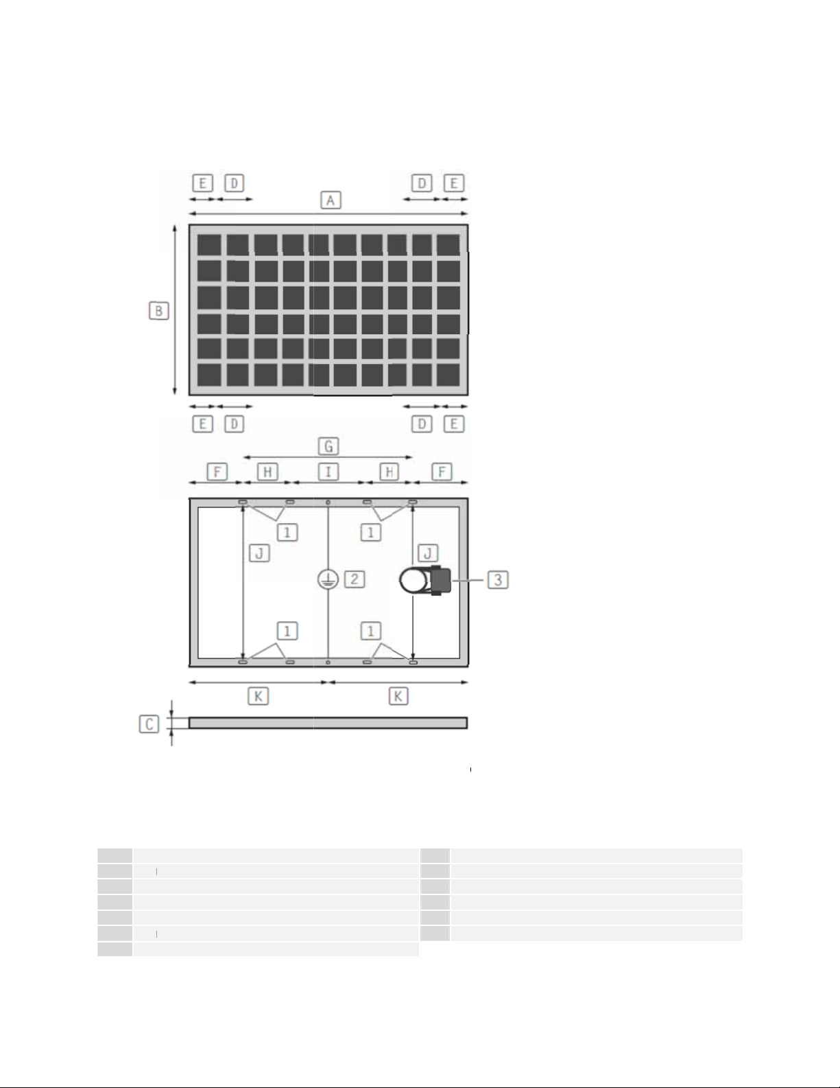
| You c
a
o
m
a
S
e
P
0
m
m
m
m
0
m
d
r
i
t
o
P
i
t
o
a
i
p
a
,
a
n
e
m
0
0
3
5
e
a
;
n
s
)
p
g
)
n
| The s
syste
withst
n find further
lar modules
must be ma
nd the loads
nstallation ins
ay be bolted
e from materi
equired.
ructions in the
r clamped in
l that is resist
installation m
lace dependin
nt to corrosio
nual for the r
g on the desig
and atmosph
spective mou
n of the frame.
eric condition
ting system.
The mountin
and able to
(J)
of
es from the fr
ounting holes
me corners
; size
(2)
and
(E
of the clampi
osition
(K)
g
of
Fig. 3–1:
areas; siz
grounding
olar module d
s
(1)
with posi
hole; position
mensions
(A)
ions and spac
f junction box
,
(B), (C)
ng
(3)
.
; sizes
(F), (G), (H)
(
D)
and distanc
(I)
and
Conergy
E 245P - 260
:
A
B
C
D
E
F
G
165
991
40
412
0m
175
130
mm
m
m
5mm
m
mm
H
25
mm
I
80
mm
J
95
mm
K
82
mm
1
9*1
4mm
2
ᴓ 4
.2mm
Page 5

Conergy PE 295P - 310P:
K
A
1956mm
B
991mm
C
45mm
D
489mm
E
0mm
F
328mm
G
1300mm
The modules have been evaluated by UL for a maximum positive design loading of 5400Pa and a negative design
loading of 2400Pa.
H
I
J
1
2
250mm
800mm
949mm
978mm
9*14mm
ᴓ 4.2mm
3.2 Mounting solar modules on installation frame
The solar modules can be damaged if the proper procedure is not followed!
| Only work in dry conditions.
| Secure the solar modules against slipping and falling.
| Do not drop the solar modules.
| Do not hold the solar module by its socket or connection cables.
| Always grasp the solar modules simultaneously at two opposite points on the module frame when lifting.
| Never carry solar modules by just one part of the frame.
| Do not expose the solar modules to mechanical impact.
| Do not touch the solar modules with sharp or pointed objects.
| Make sure the rear of the mounted solar module is not damaged even in the case of deflection due to
mechanical stress (e.g. due to snow loads).
| Do not drop any objects on the solar module and do not step on it.
| Do not drill holes in the frame of the solar module.
Attach the solar module using the four predrilled mounting holes on the underside of the frame (see Fig. 3–1). Use
corrosion-resistant stainless steel bolts only.
The solar modules can be clamped in the provided clamping areas (se e F ig. 3–1).
The clamping elements must not protrude past the edge of the frame on the glass side.
Make sure the clamping elements do not damage the frame surface or bend the frame.
3.3 Electrical installation
3.3.1 Electrical values
All relevant electrical values are specified on the label on the reverse side of the solar module.
Under normal conditions, a photovoltaic module is likely to experience conditions that produce more current and/or
voltage than reported at standard test conditions. Accordingly, the values of Isc and Voc marked on this module
should be multiplied by a factor of 1.25 when determining component voltage ratings, conductor ampacities, fuse
sizes, and size of controls connected to the PV output.
Refer to Section 690-8 of the National Electrical Code for an additional multiplying factor of 125 percent (80 percent
derating) which may be applicable.
The maximum series fuse rating for these modules is 15A.
3.3.2 General safety instructions
| Carry out the cabling in accordance with the applicable regulations.
| Make sure that the cables and connections are not damaged. Protect the cables from damage.
Page 6

Risk of electric shock. Risk of fire and injury from electric arc.
| Do not disconnect connections under load.
| Ensure sufficient protection against contact with live parts.
| Only use insulated tools.
| Do not insert any electrically conducting parts into the connectors.
| Never open the junction box.
| Make sure there is no tension in the cable when positioning and heed the specified minim um ben d radius.
| Avoid large conductor loops.
Installation shall be in accordance with CSA C22.1, Safety Standard for Electrical Installations, Canadian Electrical
Code, Part 1.
3.3.3 Parallel and serial connection
Solar modules of the same type can be connected in parallel. These solar modules are fundamentally designed for
series connection.
Material damage due to connection errors.
| Only use solar modules of the same type and output for parallel connection. Take measures for overcurrent
protection (e.g. line fuse) if necessary. Never exceed the specified maximum series fuse rating of the solar
modules.
| Make sure that only solar modules with the same amperage (Impp) are connected in series and make sure that
the string voltages are the same. Even at low temperatures, never exceed the maximum permissible system
voltage of the solar modules.
| Make sure that the number and connection of the solar modules match the electrical values specified by the
devices connected to the photovoltaic system.
| Use only 90ºC wet-rated, sunlight resistant, stranded or solid conductor cables for all modules and interconnect
wiring that may be exposed to weather.
| Make sure that the polarity is correct.
3.3.4 Connecting the photovoltaic module
On the rear of the solar module, there is a connection box with the connection cables, the plug and the socket.
Connection cable length 1000mm
Connection cable cross section 4mm
Allowable ambient temperature range for cables from -40°C
to +85°C
All Details for wiring should be in accordance with the NEC guidelines, and the grounding method of the frame of
arrays shall comply with the NEC, article 250.
²
3.3.5 Grounding
Equipment grounding requirements must be checked in accordance with the applicable regulations and standards
before work is started. The module frame or array must be grounded to avoid the hazards of electric shock or fire.
The position of possible grounding connections can be found in Fig. 3-1.
The grounding wire can be mounted on one of the designated holes in the module frame (see Fig. 3–1).
Avoid contact corrosion when using different metals and observe electro-chemical insulation ratings.
An equipment grounding conductor can be fixed to the holes in the frame. Copper ground wire or equivalent to be
used: #12 AWG.
Observe the applicable regulations.
Page 7
G
G
A
a
p
s
e
h
s
h
s
g
s
c
f
f
p
e
u
n
W
o
u
a
i
o
o
n
c
u
o
e
s
y
w
m
0
e
m
m
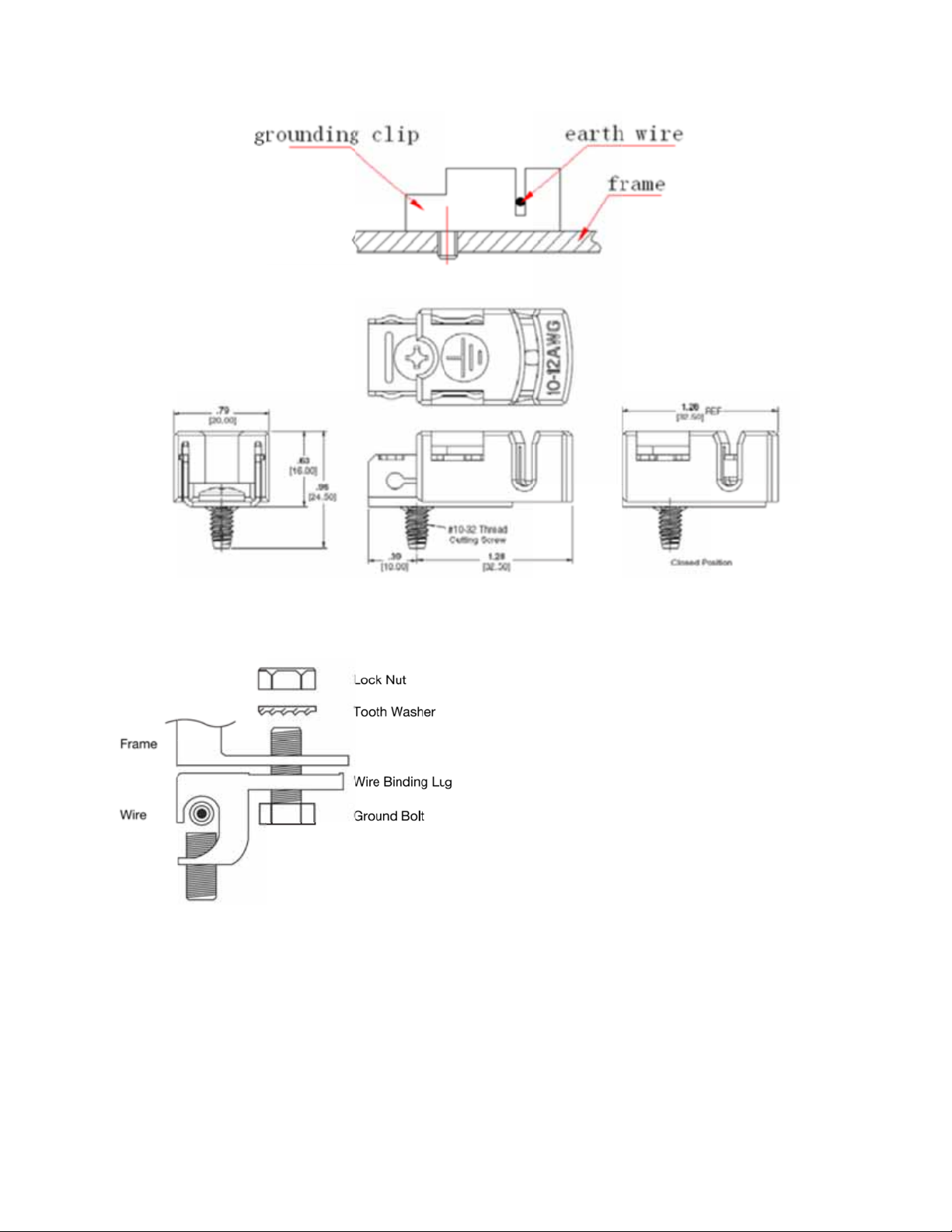
Fig. 3-2:
Figure 3-2
rounding met
above display
ods
one method
or grounding
using TYCO l
g #1954381-1
(UL Certificat
No.E69905).
Fig. 3-3:
Figure 3-3
similar)
ddition
Conergy a
Electronic
the requir
rounding met
above display
l Groundin
proves the u
) Washer Ele
ments of UL-4
ods
one method
Methods
e of UL-467 a
trical Equipm
67 as suitable
or grounding
proved bondi
nt Bonding (
for electrical b
sing UL-467
g and ground
EEB) and simi
nding and gr
pproved grou
ng devices, in
lar devices, s
unding PV m
d lug (such a
luding Burnd
ch as barbed
dules to PV
Burndy CL-5
(formerly Wil
ashers, that
ounting syste
or
y
eet
s.
Page 8

4 Maintenance and care
The solar modules are low-maintenance modules. However, Conergy recommends that a visua l insp ection of the
mechanical and electrical connections be performed once a year to detect any damag e.
Dirt on the solar modules reduces the output and the yield. If the solar modules are installed with an inclination angle
of more than 15°, they will generally be adequately cleaned by the rain.
Damage to the solar module surface can occur by scratching or extreme differences in temperature.
| Only use pH neutral liquid cleaner, even if there is excessive dirt build-up.
| Do not use abrasive cleaning agents
| Ensure cleaning solutions are at roughly the same temperature as the solar module surface.
| Wipe the solar module surface with water and a soft cloth.
| Never attempt to rub or scratch off dirt particles.
5 Removal
Risk of electric shock.
| Do not touch any bare connection parts.
| Only use insulated tools.
1. Disconnect the inverter from the utility power on the AC side so that the photovoltaic system has no load.
2. Disconnect the photovoltaic system from the inverter at the cutoff point on the DC side.
3. Make sure that the system is not supplied with voltage.
4. Remove the photovoltaic system in the same way as it was installed; observe the safety instructions.
6 Disposal
Do not dispose of old or defective solar modules with normal household waste.
Please ask your installer, dealer or Conergy AG about disposal.
7 Technical Data
The electrical characteristics are within +/-10 percent of the indicated values of Isc, Voc and Pmax under standard
test conditions (irradiance of1000W/m², AM 1.5 spectrum and a cell temperature of 25°C (77°F)).
Open
Circuit
Voltage
(Voc)
37.45V
37.54V
Module Type
Conergy PE 245P
Conergy PE 250P
Maximum
Power
(Pmax)
245Wp
250Wp
Conergy PE 255P 255Wp 37.62V 8.88A 30.36V 8.40A 1000V
Conergy PE 260P 260Wp 37.73A 8.91A 30.77V 8.45A 1000V
Conergy PE 295P
Conergy PE 300P
295Wp
300Wp
45.09V
46.08V
Conergy PE 305P 305Wp 46.20V 8.60A 36.97V 8.25A 1000V
Conergy PE 310P 310Wp 46.30V 8.69A 37.04V 8.37A 1000V
Conergy reserves the right to make changes to this installation manual without prior notice.
The pictures and drawings in this installation manual are only intended for illustration purposes and may vary from reality.
Short
Circuit
Current
(Isc)
8.78A
8.84A
8.48A
8.53A
Maximum
Power
Voltage
(Vmpp)
29.63V
29.98V
36.60V
36.82V
Maximum
Power
Current
(Impp)
8.27A
8.34A
8.06A
8.15A
Maximum
System
Voltage
1000V
1000V
1000V
1000V
Page 9

OUR WORLD IS FULL OF ENERGY.
www.conergy.us | www.conergy.ca
Conergy_PE Solar Module_UL_IM_ENG_2013-03-22 Subject to technical changes 2013 © Conergy
 Loading...